
You are currently viewing a beta version of our website. If you spot anything unusual, kindly let us know.
Preprint
Article
Simulated And Experimental Study Of The Available Energy Transfer From An Ev Battery In A V2g System
Altmetrics
Downloads
58
Views
15
Comments
0


This version is not peer-reviewed
Abstract
ABSTRACT
The work is focused on determining the energy transfer from EV’s to grid for different operating conditions. The study has been simulated on a scaled model and later validated through experimental tests on batteries of 20 kWh, 40 kWh, 60 kWh and 80 kWh for EV’s energy rates from 130 Wh/km to 180 Wh/km. Tests have been developed to evaluate the energy transfer from driving distance between 0 and 50 km. Results have proved there is a linear dependence between energy transfer and energy rate. Experimental and simulated values have been correlated showing a 99.6% accuracy. The ratio of energy transfer to battery energy capacity depends not only on this latter parameter, but also on the energy rate of the electric vehicle. Experimental tests have shown a variation from a minimum transfer ratio of 54.1% for the highest electric vehicle energy rate and lowest battery energy capacity and power transfer to grid rate to a maximum of 88.6% for the highest power transfer to grid rate and battery energy capacity and lowest electric vehicle energy rate.
Keywords:
Subject: Engineering - Energy and Fuel Technology
1. Introduction
Electric energy dependence is growing in modern society with the development of appliances and utilities that use this kind of energy. According to the IEA, the world average electrical energy per capita is 2.674 kWh per person per year, although this consumption is irregularly distributed around the world, with values as high as 12.071 kWh for the United States to as low of 1.181 kWh for India, with China in an intermediate position with a rate of 4.475 kWh per person per year [1]. These data reflect that the more developed a modern economy is, the more electrical energy it consumes, since modern economies depend on the reliable and affordable delivery of energy; however, the preservation of the environment requires a drastic change in the electricity generation and distribution. Electric energy is growing so fast that in the next 25 years its growth is going to outpace the global energy consumption [2]. This situation drives to a more effective use of the electric energy as well as to a better distribution of the electricity delivery. On the other hand, the continuous growing of world population, especially in third world countries, forces to search the increasing of the electricity generation to supply energy demand. From the well know expression T=SR (1), where T is the electric energy raising rate, S the population growing rate, and R the raising of electricity per capita rate, using data provided by the IEA [3] and WEO [4], it is expected a population growing rate from 0.2% in OECD countries to 3.4% in non-OECD countries [5], and an electricity per capita growing rate of 0.3% in developed countries (OECD) and 4.8% in non-OECD countries. These values result in an increasing requirement of electricity generation from 0.5% to 8.1% depending on the world region. The average value of this wide interval matches with predictions of the IEA [6].
The moderate to high electricity growing rate has been covered by the release of energy from conventional power plants or renewable energy sources, which nowadays are spread out for many regions of the world. In developed countries the access to electric energy is not a problem, since the electric network is widely developed; this situation is not as good in emerging countries, and especially in non-developed countries, where access to electricity is a big problem. This problem comes from a deficient distribution of electric energy from power plants due to the lack of an appropriate network, penalizing the way of life and human development. In other countries the geographical structure does not allow the development of an appropriate electric network, which may cause a serious dependence on conventional generation plants operating with fossil fuel [7].
Conventional way of distributing the energy resides in a radial network that transports electricity from a power plant to the final destination. Currently, power plants are located far from population centers, since people do not want to have these facilities in the nearby; this situation forces the electric network to cover long distances, many times at a high cost, what reduces the chances to get access for very small population centers and isolated communities. A solution is the so called Distributed Generation (DG), which implies the use of power plants in the vicinity of the population centers not connected to the electric network, operating at low voltage. These power plants must be of reduced size, since conventional power plants cannot be minimized at a feasible cost; the only chance to get this solution is through the use of renewable energies. Moreover, electric vehicles can replace the use of conventional systems of energy generation, like gas power plants, to stabilize the grid [8].
Despite conventional power plants or DG systems may provide a full coverage of electricity demand, a new problem arise derived from human habits, the gap between generation and use of energy. In effect, power plants are currently designed to optimize their performance; therefore they are operated at a constant generation rate to obtain an optimum efficiency of the energy conversion process [9]. In conventional power plants the size must be large to compensate for economical investment, what makes them unaffordable for Distributed Generation plants of much smaller size. The use of renewable energies are not always possible if the resource is not available in the location where the DG plant is intended to place.
A feasible solution arises to solve the gap between generation and use, the storage of electric energy during the period the generation exceeds the use and the release of the stored energy at the opposite period, when generation cannot cover energy demand. The main problem derived from this solution is the need of huge electric accumulators to store the excess of electric energy during the period of abundance. Nevertheless, the modern society counts on an already accessible solution, the electric vehicle; although individually considered an electric vehicle (EV) does not provide enough capacity to absorb the surplus energy generated, a large number can store such excess without difficulty, like the vehicle fleets [10], this is the base of the Vehicle-to-Grid (V2G) technology. Likewise, electric vehicles batteries can play the role of a power generator if current is drained from the battery, transferring energy to the grid; this can laminate the power peaks of the energy demand as well as to balance the gap between power generation and energy use [11]. Besides, electric vehicle batteries can play the role of giant accumulators for the grid to compensate the surplus of generation [12]. On the other hand, EV batteries can also compensate for current harmonics and reactive power as well as operate as active filter in smart grids [13].
V2G is a recent technology developed to use batteries in EV as electric exchangers with the network. The EV batteries, however, can play an additional role as DG systems in places where electric energy is not accessible. In this situation, the EV battery acts as a power system that supplies electricity to a local network with the only requirement of preserving some charge in the battery to get back the recharging point, wherever it is. Battery in these conditions is subject to a deep charge-discharge cycling that may affect its performance, thus the amount of energy that can be transferred to the grid. Recent studies have demonstrated the influence of the battery capacity in transferring energy to the grid and how this affects to the potential of the V2G system [14].
2. Battery Performance
Lithium-ion batteries are the most common type used in electric vehicles due to their high specific energy and power as well as their versatility, since they can supply high amount of energy at low power and vice versa.
Any type of battery is characterized by its V-t curve that shows how the battery voltage is evolving with time for a specific discharge current. In the case of Li-ion batteries (Figure 1) it can be seen that after initial voltage decay, activation process, the voltage remains almost constant until the cut-off point where battery collapses. This constancy in the voltage value makes the battery very suitable for supplying electric energy to a local network, since the DC/DC converter or DC/AC inverter operates at a fixed point with maximum efficiency [15].
Discharge curve evolves with current rate modifying the battery capacity, as reflected by authors [17], thus affecting to the energy delivered by the battery in a full discharge. When the battery is connected to a local network, discharge current is modified with energy requirements, and the battery capacity is continuously changing; in such a case, the critical parameter to determine the performance of the battery is the State-of-Charge (SOC) or its complementary parameter, the Depth-of-Discharge (DOD).
The DOD coefficient can be easily determined from the classical expression:
where ID and tD are the discharge current and time, and Cr the real capacity of the battery for the specific discharge conditions, which is given by:
Cn is the nominal capacity of the battery for the standard discharge rate, and f and fref the capacity correction factor for the specific and standard discharge that can be obtained from the expression:
In case of successive partial discharges at different current rate, the DOD value must be determined from the cumulative discharge of every discharge; mathematically:
Applying equations 2 and 3:
In case the battery is completely depleted, DOD|G=1.
Discharge current, Ii, can be expressed in terms of battery capacity using the discharge rate coefficient, M, thus equation 5 is transformed into:
Assuming the electric vehicle battery has already used the specific energy for an initial trip, equation 6 should be modified according to:
where Vbat is the battery voltage, ξr is the electric vehicle energy rate, in Wh/km, and d the returning travelling distance, in km. It is assumed that a recharging point is available at the end of the returning travel.
Term into brackets in equation 7 depends on how much current is drained from the battery and how long the discharge lasts. Provided the battery voltage, nominal capacity, standard discharge time, energy rate and travelling distance are known, the only variable parameters are current and discharge time; therefore:
With
If we apply the Ohm’s law for the local network energy requirements:
where Vnw is the network operating voltage and Pithe demanded power.
The operational value of the DOD coefficient can be calculated either using equations 7 or 9 depending on which parameter is known, the discharge current rate, M, or the required power from the network, P.
Maximum DOD|op value for a battery depends on the use conditions, since an electric vehicle battery that exchanges energy to the network may require some charge to move the vehicle after the exchange process. This situation shows up when the electric vehicle is parked for a while and the owner moves the vehicle to another place before recharging the battery; in this case, the battery cannot be completely depleted. Applying this condition:
where DODrt is the depth of discharge for the returning trip, and the super-index ex indicates real charge extraction. Coefficient A is given by:
The B value is currently calculated for energy use under standard discharge conditions, which is not the current situation since the returning driving mode does not match standard conditions; therefore, we have to correct the B value according to real driving conditions. This calculation results complicated since the driving conditions are not constant, what makes the draining current from the battery to change, thus the capacity correction factor. To solve this problem we introduce a security factor, FS that takes into account the variation of discharge rate, thus warrantying a safe return to the recharging point. Equation 10, then adopts the form:
The security factor, FS, can be obtained from statistical analysis comparing real driving conditions and ideal driving mode that matches standard discharge rate. A simulation study [19] has given a value of FS=1.045
For every single process:
And considering the returning and initial trip are running under the same conditions:
That provides the available depth-of discharge for every single process.
Assuming the battery is completely depleted in a daily cycle:
From equation 15 we can obtain discharge time for every process as:
The energy transfer to the network is given by:
where the time interval during discharge that takes into account the change in the battery capacity as the discharge process is going by, can be obtained from the following equation:
3. Simulation Process
To determine the amount of deliverable energy from the electric vehicle battery at different operation conditions, a simulation process has been developed on a battery model; the battery is made up of a block of 4 elements of 4.2 V lithium-ion cells for a total voltage of 16.8 V. The battery capacity is 26 Ah rated at 20 h discharge time. The electric vehicle prototype battery is 20 kWh, 40 kWh, 60 kWh and 80 kWh. According to these values, we have to establish a power ratio between prototype and model to reproduce real operating conditions, this power factor is given by:
where P indicates power, V voltage, and C capacity, with sub-indexes p for prototype and m for model.
Predicted values have been obtained using equations from the above section. The simulation has been run for the four tested cases, with simulated battery energy capacity of 20 kWh, 40 kWh, 60 kWh and 80 kWh. Predicted performance of every simulated battery has been obtained for different electric vehicle energy rate, from 130 Wh/km to 180 Wh/km in steps of 10 Wh/km. The simulation has been extended for daily driving distances up to 50 km, from 1 to 25 km way and back, in steps of 1 km.
Simulation of the battery discharge rate has been adjusted proportionally to the required power from the grid. The tested required power has been of 1 kW, 5 kW, 10 kW, 25 kW and 50 kW. The simulation has considered that the battery is completely depleted in a daily cycle. Simulated results provide the predicted value of the available amount of energy that can be transferred from the battery as a function of the driving distance, battery capacity, energy rate and required power transfer.
To validate the simulation procedure all combinations of involved parameters, driving distance, power transfer to the grid, battery energy capacity, and electric vehicle energy use rate, have been carried out for a total number of 3120 tested cases.
The expression to determine the available amount of energy transfer, ξt, is given by:
where d is the driving distance and m the slope of the correlation function that can be obtained from the relation:
The sub-index i refers to the testing case and 0 corresponds to the initial reference value, which in our case has been 130 Wh/km. This reference value, however, can be modified depending on the range of the energy use rate of the electric vehicle.
The coefficients in equation 21 have proved to be valid for all tested cases.
The origin coordinate in equation 20, ξo,i, can be determined using the following expressions, where the last value between parenthesis indicate the battery energy capacity for which the corresponding equation is valid:
Since the range of study is limited, to extend the range of study we have correlated the two coefficients of the above expressions to the energy capacity of the battery, ξbat, obtaining the following relations:
Therefore, equation 22 can be expressed, in general terms, as:
Performance in energy transfer can be obtained from the expression:
The performance value indicates how efficiency is the energy transfer process for the specific operating conditions.
4. Experimental Tests
To validate the simulation process we have run experimental tests reproducing the simulated conditions in the aforementioned battery block. To reduce time of operation, four identical battery blocks have been used, simulating the four prototype batteries of 20 kWh, 40 kWh, 60 kWh and 80 kWh energy capacity. To adapt tests to simulation each block has been tested using a different power ratio, according to the energy capacity of the prototype battery. The power ratio has been obtained using equation 19.
Energy transfer to the grid has been done using an automatic discharger unit that can be set up to drain current from battery according to the specific power transfer. This draining current is determined through the equation:
The factor for the discharge current in equation 26, fI, has been obtained applying the Ohm’s law, from the equation:
Using the values for the battery of the simulated electric vehicle and the model one, we have (Table 1):
First group of tests have been run until the battery is completely depleted, since the zero driving distance has been applied. Discharge current was set up using the expression:
where the average value of the voltage, , is taken as the voltage at the half point of the discharge, since the voltage decay is linear. Considering the values from Table 2, and taking into account the average value of the batteries used in our tests is 15.8 V, the discharge current has adopted the following values:
Batteries discharge was run for the simulated processes, resulting in the energy drained from the battery shown in table 2. The discharge process has been controlled by an automatic discharge unit, DIGAMEL mod. BDX96-200USB-DGM, that supports a constant discharge within 0.001 A of accuracy. The energy drained from the battery has been obtained from the discharge capacity and the battery voltage, both parameters measured by the discharge unit and registered in a PC using the associated software. Experimental values are shown in Table 3.
Using the corresponding power ratio for the different battery energy capacity simulations, we obtain the estimated values for a real prototype based on the experimental results from Table 3. The values contained in Table 4 correspond to the prediction for energy transfer in real conditions in DC current.
The correlation factor corresponds to the ratio between estimated and simulated values, and gives the quality of the adjustment of simulation to real conditions, which is excellent.
Since the current injection into the grid must be in alternate current a VICTRON Phoenix 24|800 DC/AC inverter of 800 W maximum output power has been used to convert direct into alternate current. The results are shown in Figure 2.
Figure 2 shows the experimental energy transfer from battery to grid, in AC current, for the battery energy capacity of 20 kWh, 40 kWh, 60 kWh and 80 kWh, at the five power transfer rates, 1 kW, 5 kW, 10 kW, 25 kW and 50 kW, as a function of the electric vehicle energy rate. It can be noticed that the evolution of the energy transfer is linear in all cases, decreasing with the increase of the energy rate. The slope of the energy transfer variation is almost constant for the four tested battery energy capacities, as well as for the different power rates, what indicates the power transfer rate has a little or minimal influence on the performance of energy transfer evolution, only in the absolute values of the energy that is transferred from battery to the grid. On the other hand, this behavior confirms the validity of the linear simulation expressed in equation 22.
Second part of the work was devoted to determine the performance of the battery, as for the energy transfer capacity, in case a non-zero driving distance is considered.
To simulate the energy used in the driving mode we have supposed an electric engine of 400 V for the vehicle prototype that gives a voltage ratio of 23.8; using data from Table 1 and this voltage ratio we have obtained the power ratio for the different battery energy capacity whose values are shown in Table 5.
The discharge current from the battery for the different EV energy rates has been obtained using the average voltage of the battery during discharge, the average driving speed in urban routes and the power ratio values indicated in Table 5 according to the expression:
Assuming an average driving speed of 30 km/h, which is a current value for urban routes, we have:
Tests were run at the specific discharge current indicated in Table 6 for the corresponding time to the simulated driving distance, computed at average speed of 30 km/h. The process was applied to all simulation conditions, different energy rates and battery energy capacity.
After having discharged the battery for the simulated driving distance, we submitted the battery to a discharge process according to the simulated power transfer conditions, as in the first group of tests until the battery is completely depleted.
As the variation in operating conditions modifies the real capacity of the battery, we have determined this value for the different situations arisen from the driving routes simulation in Table 7; using equations 2 and 3 we have obtained:
It can be observed the capacity reduction in the battery model because of the operating conditions may produce a maximum energy loss in the prototype of 0.5 kWh, which represents a 2.5% of the global capacity of energy transfer from battery to grid; this percentage should be taken into account in specific cases when the number of electric vehicles transferring energy to the grid is high.
Applying the reduction in battery capacity to the effective available energy in the battery, we proceeded to determine the energy transfer from battery to grid in real conditions as a function of the driving distance for every battery energy capacity and electric vehicle energy rate. The results of the experimental tests are shown in the following Figure 3(a to e).
Labels next to every group of lines represent the energy capacity of the battery. The energy rate of the electric vehicle is represented by different type of drawing lines, whose labels are, inside the figure frame, at the top. The driving distance represented in the X-axis corresponds to one way trip, although the values of the energy transfer have been computed for the round trip.
We observe there is a linear dependence of the energy transfer on the driving distance for every power transfer, electric vehicle energy rate and battery energy capacity, in good correspondence with the simulation linear evolution represented in equations 22 and 24. As it is expected, the linear evolution of the energy transfer shows a decreasing trend with driving distance, increasing the slope with the energy rate of the electric vehicle. It can also be noticed that the evolution of the energy transfer with driving distance is quite similar for any battery energy capacity.
Experimental values show that the energy transfer diminishes with increasing power transfer rate indicating the influence of the current rate onto the discharge process because of the lower capacity of the battery for higher discharge rate. On the other hand, the electric vehicle energy rate also influences the energy transfer capacity, increasing the slope of the lowering trend, as expected.
We have also determined the efficiency of the energy transfer using the equation 25 obtaining the results presented in Table 8. The values represent the average value for the whole range of driving distances for every energy rate.
Analyzing the results, we notice that for a given energy rate and battery energy capacity the average efficiency remains almost constant for the different power transfer values; however, the efficiency declines as the energy rate increases for any power transfer rate and battery energy capacity value. The efficiency also declines with the battery energy capacity for the same power transfer value. The largest variation in the efficiency corresponds to the lowest battery energy capacity, 20 kWh, within a 12.5% deviation, on average, while for the other energy capacities is rather low, with maximum average deviation between 3.5% and 1.5%.
5. Conclusions
A simulation process has been developed to estimate the energy transfer from an electric vehicle battery to the grid as a function of the battery energy capacity, power transfer and electric vehicle energy rate.
The simulation has been run considering the battery is completely depleted every day. The simulation also considers two types of situations, the one where the vehicle is parked all day long and the other where the vehicle is used for daily urban routes, with a round trip distance from 2 to 50 km.
The simulation has determined the energy transfer can be obtained through a linear relation that depends on the battery energy capacity and energy rate of the electric vehicle.
Experimental results have been correlated to the theoretical prediction using the simulation algorithm for the zero driving distance, showing a very good agreement, better than 99.6%, proving the validity of the simulation process.
Likewise, experimental tests have been run, simulating daily urban routes from 2 to 50 km round trip, applying the algorithms developed in the simulation; results are in good agreement with predicted values, within 99.6% accuracy, as in the case of zero driving distance.
The ratio of energy transfer to battery energy capacity depends not only on this latter parameter, but also on the energy rate of the electric vehicle. Experimental tests have shown a variation from a minimum of 37.3% to a maximum of 88.9%. The ratio increases with the battery energy capacity, but reduces with the energy rate of the electric vehicle.
The low values of the efficiency in the energy transfer, for the 20 kWh battery, indicates the low energy capacity batteries are not very suitable for energy transfer to the grid.
References
- International Energy Agency. Global Energy report. Data and Statistics. (2020).
- International Energy Agency. Fuels and Technology report: Electricity. September, 16th, 2020.
- International Energy Agency. Electricity per capita consumption. Overview. (2020).
- International Monetary Fund. World Economic Outlook Report (2020).
- OECD Data (2018).
- International Energy Agency. Electricity Information. Statistic reports. July 2020.
- Muhammad Huda, Muhammad Aziz and Koji Tokimatsua (2018) Potential ancillary services of electric vehicles (vehicle-to-grid) in Indonesia, Energy Procedia, Vol.152, p.1218-1223. [CrossRef]
- Pedro Nunes and M.C. Brito (2017) Displacing natural gas with electric vehicles for grid stabilization, Energy, Vol.141, p.87-96. [CrossRef]
- A.K. Raja, Amit Prakash Srivastava and Manish Dwivedi, Power Plant Engineering, New Age International (P) Limited Publishers, New Delhi (2006) ISBN (13): 978-81-224-2333-4.
- Toon Meelen, Brendan Doody and Tim Schwanen (2020) Vehicle-to-Grid in the UK fleet market: An analysis of upscaling potential in a changing environment, Journal of Cleaner Production, On-line, 19 November, 125203. [CrossRef]
- Cong Zhang, Jeffery B. Greenblatt, Pamela MacDougall, Samveg Saxena, Aditya Jayam Prabhakar (2020) Quantifying the benefits of electric vehicles on the future electricity grid in the midwestern United States, Applied Energy, Vol.270, 115174. [CrossRef]
- H.Ben Sassi, C. Alaoui, F. Errahimi, N.Es-Sbai (2020), Vehicle-to-grid technology and its suitability for the Moroccan national grid, Journal of Energy Storage, On-line 5 November, 102023. [CrossRef]
- Vítor Monteiro, J.G. Pinto ND João L. Afonso (2019) Improved vehicle-for-grid (iV4G) mode: Novel operation mode for EVs battery chargers in smart grids, International Journal of Electrical Power & Energy Systems, Vol.110, p.579-587. [CrossRef]
- Yiling Liu, Haiyang Lin, Wang Yu, Liu Luyao, Qie Sun and Ronald Wennersten (2018) Influence of the Electric vehicle battery size and EV penetration rate on the potential capacity of Vehicle-to-grid, Energy Procedia, Vol. 152, p-630-635. [CrossRef]
- C. Armenta-Deu & J.P. Carriquiry (2020) Scale Simulation of Battery Performance for Electric Vehicles, International Journal of Vehicle System Modelling and Testing (pending of publication). [CrossRef]
- Li-ion Voltage Analysis. Silicon Lightworks. Pompano Beach, FL 33073, USA.
- C. Armenta-Déu and J.P. Carriquiry (2019) Application of Statistical Method to Determine Lithium Battery Capacity for Electric Vehicles, Journal of Automobile Engineering and Applications, Vol.7, Issue 2, p.25-35. [CrossRef]
- C. Armenta-Déu, J.P. Carriquiry and S. Guzmán (2019) Capacity correction factor for Li-ion batteries: Influence of the discharge rate, Journal of Energy Storage, Vol.25 100839. [CrossRef]
- M. Hanako Olmedilla (2020) Modeling and Simulation of Lithium-ion battery performance for Electric Vehicles. Master Thesis. Universidad Complutense de Madrid.
Figure 1.
Voltage vs State-of-Charge evolution for a Li-ion battery [16].
Figure 1.
Voltage vs State-of-Charge evolution for a Li-ion battery [16].
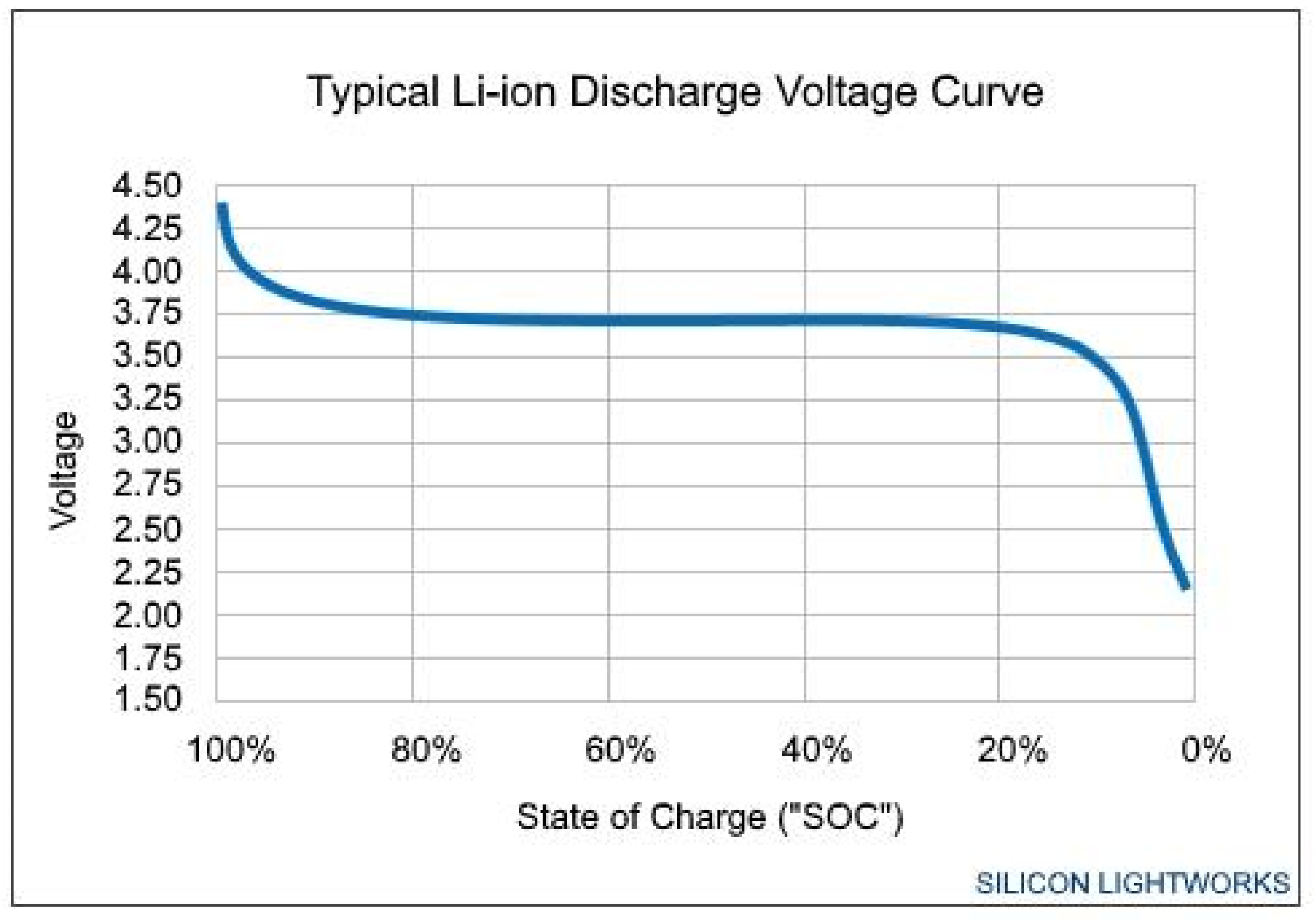
Figure 2.
Battery to grid energy transfer (zero driving distance).
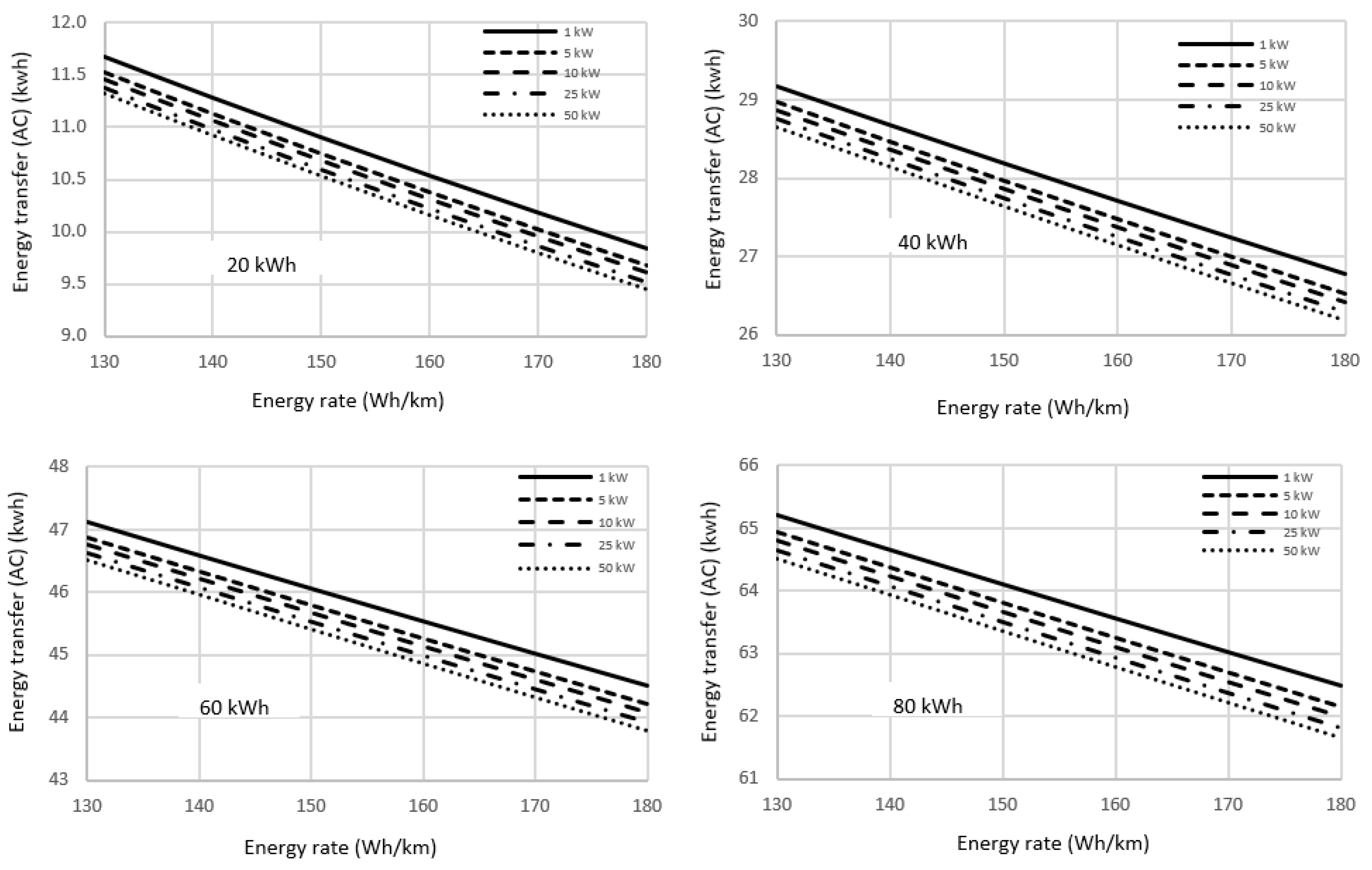
Figure 3.
a. Battery to grid energy transfer vs. driving distance (Power transfer: 1 kW). b. Battery to grid energy transfer vs. driving distance (Power transfer: 5 kW). c. Battery to grid energy transfer vs. driving distance (Power transfer: 10 kW). d. Battery to grid energy transfer vs. driving distance (Power transfer: 25 kW). e. Battery to grid energy transfer vs. driving distance (Power transfer: 50 kW).
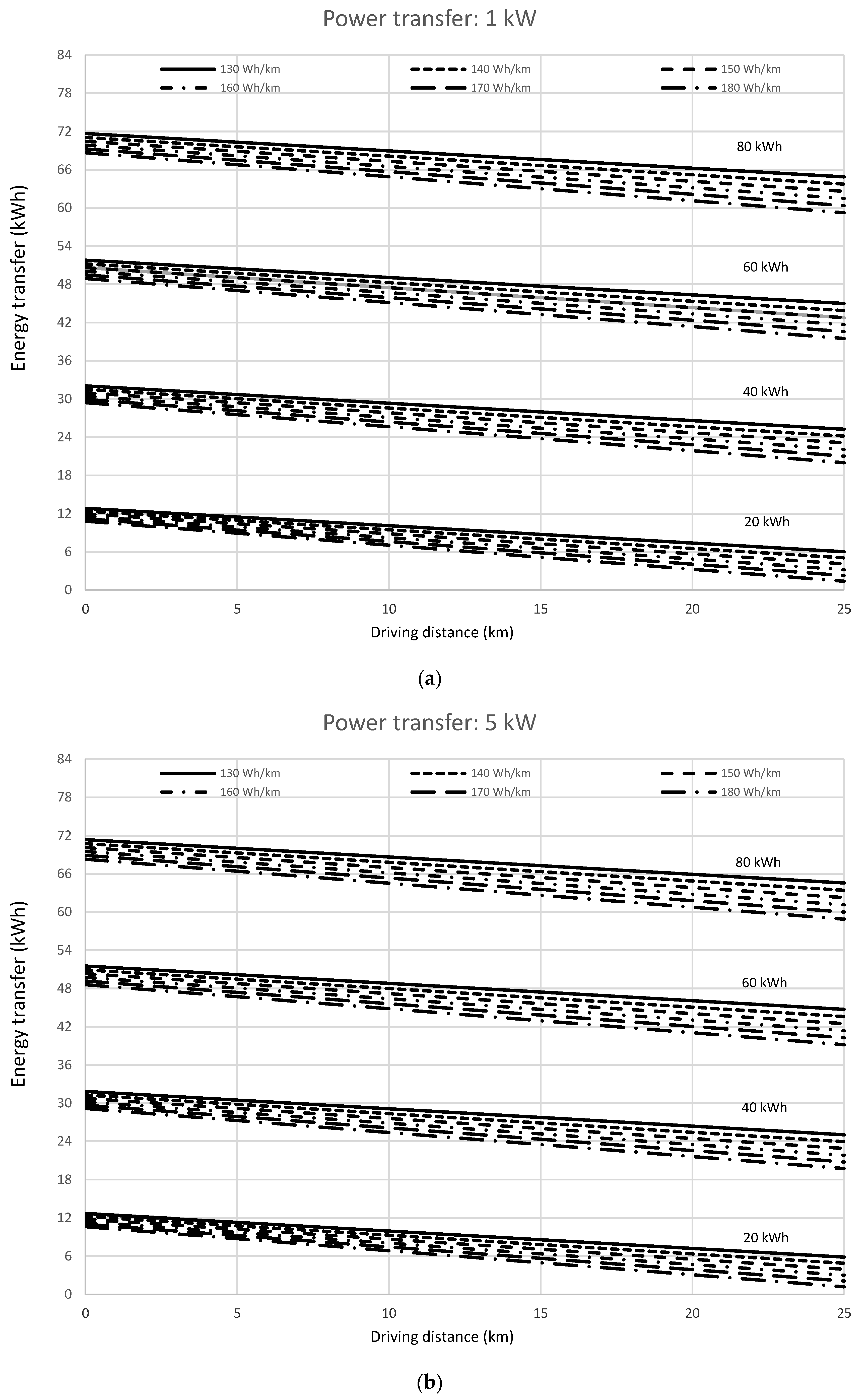
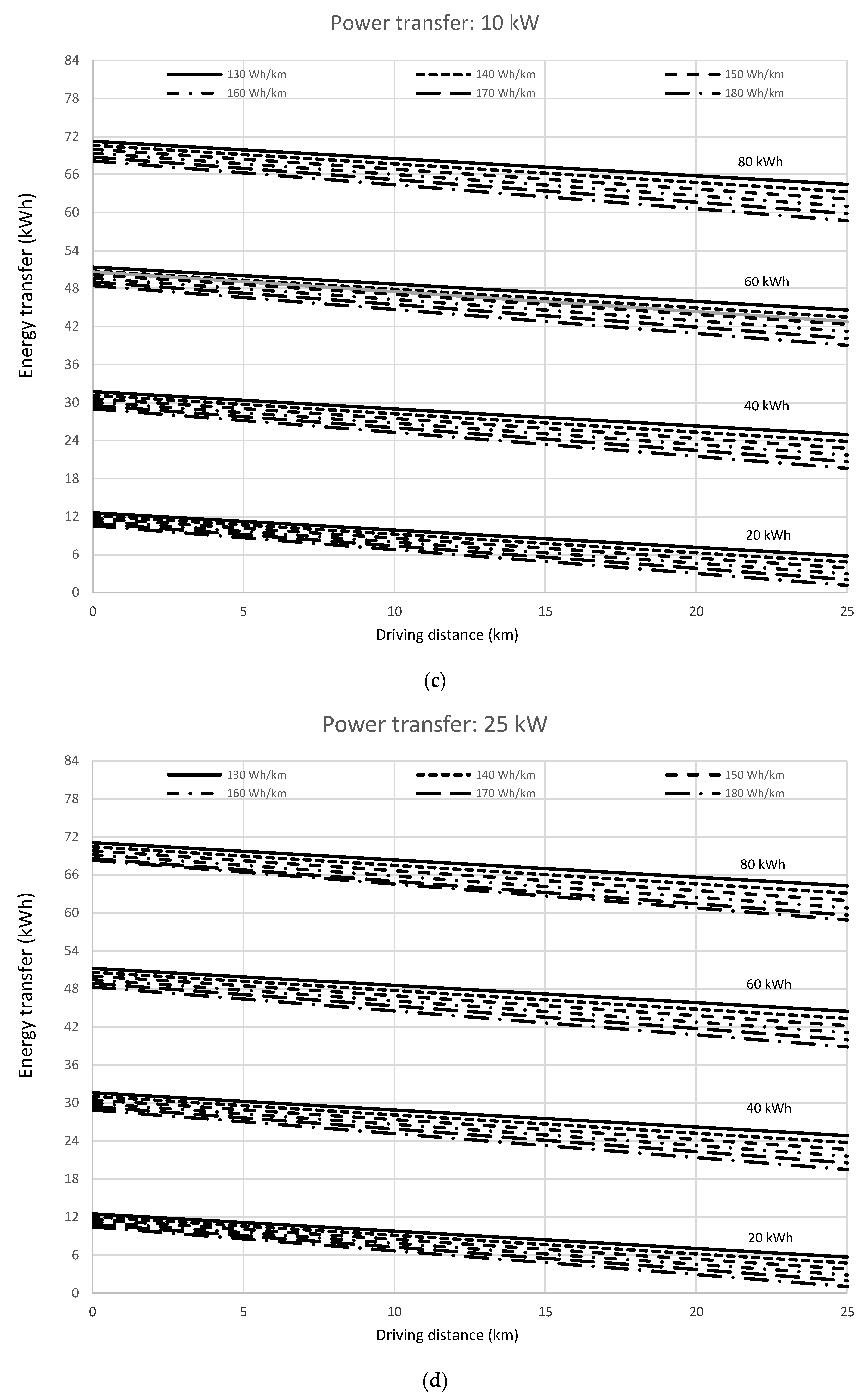
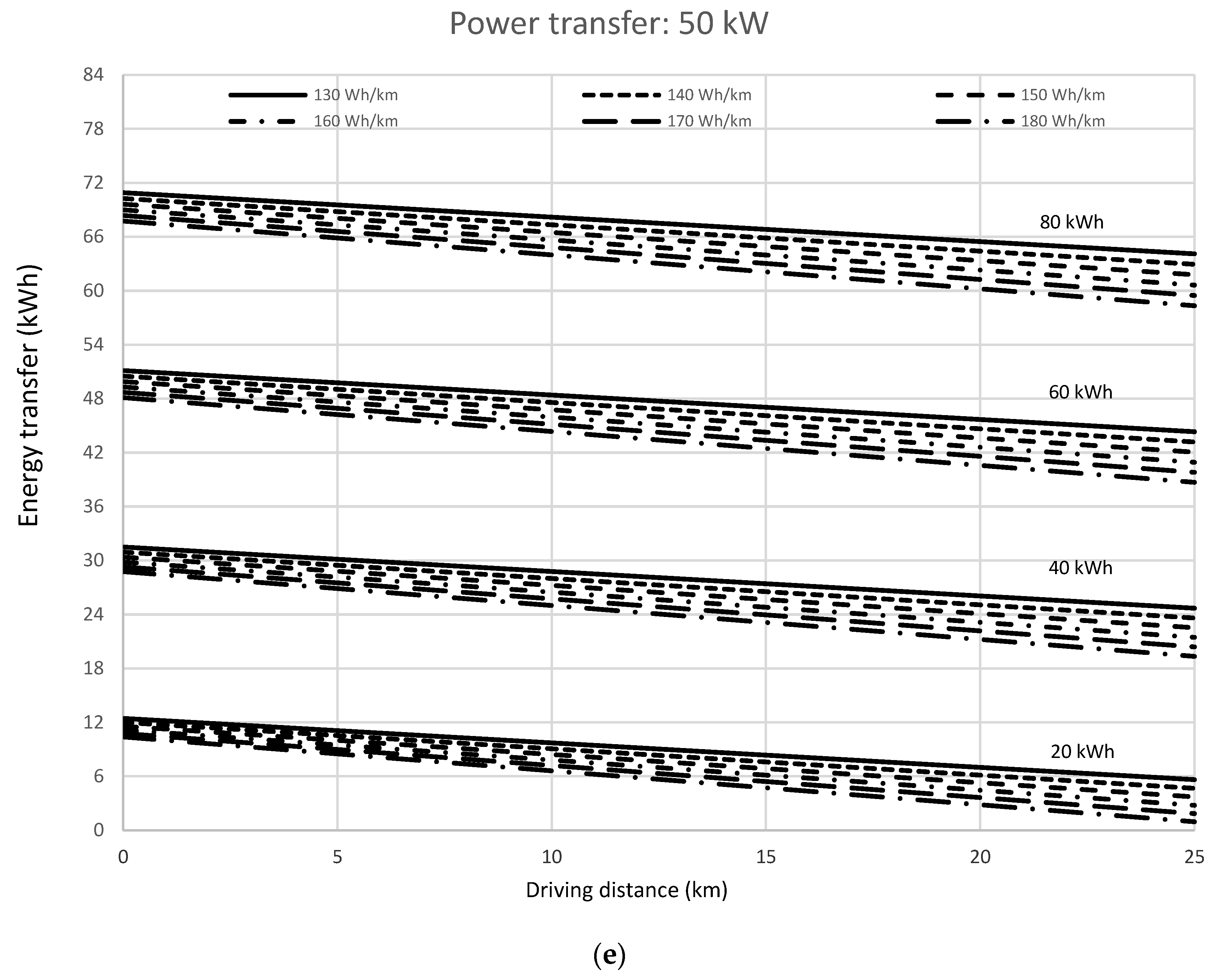

Table 1.
Current ratio for the modeled prototype batteries.
| Battery energy capacity (kWh) | 20 | 40 | 60 | 80 |
| Current ratio | 1,923 | 3,846 | 5,769 | 7,692 |
Table 2.
Discharge current (A) (model).
| Power transfer rate (kW) | |||||
|---|---|---|---|---|---|
| (ξbat)p (kWh) ↓ | 1 | 5 | 10 | 25 | 50 |
| 20 | 1.382 | 6.911 | 13.823 | 34.557 | 69.114 |
| 40 | 0.691 | 3.456 | 6.911 | 17.278 | 34.557 |
| 60 | 0.461 | 2.304 | 4.608 | 11.519 | 23.038 |
| 80 | 0.346 | 1.728 | 3.456 | 8.639 | 17.278 |
Table 3.
Energy drained from the battery (Wh) (experimental).
| Power transfer (kW) | Battery energy capacity (kWh) | Energy rate (Wh/km) | |||||
|---|---|---|---|---|---|---|---|
|
130 |
140 |
150 |
160 |
170 |
180 |
||
|
1 |
20 | 280.2 | 270.8 | 261.7 | 252.9 | 244.5 | 236.3 |
| 40 | 350.0 | 344.1 | 338.2 | 332.5 | 326.9 | 321.3 | |
| 60 | 377.0 | 372.7 | 368.5 | 364.3 | 360.2 | 356.1 | |
| 80 | 391.3 | 388.0 | 384.7 | 381.4 | 378.1 | 374.9 | |
|
5 |
20 | 276.7 | 267.2 | 258.0 | 249.2 | 240.6 | 232.4 |
| 40 | 347.6 | 341.5 | 335.6 | 329.7 | 324.0 | 318.4 | |
| 60 | 375.1 | 370.7 | 366.4 | 362.1 | 357.9 | 353.7 | |
| 80 | 389.6 | 386.2 | 382.8 | 379.5 | 376.2 | 372.9 | |
|
10 |
20 | 275.2 | 265.7 | 256.5 | 247.6 | 239.0 | 230.7 |
| 40 | 346.5 | 340.4 | 334.4 | 328.5 | 322.8 | 317.1 | |
| 60 | 374.2 | 369.8 | 365.4 | 361.1 | 356.9 | 352.7 | |
| 80 | 388.9 | 385.4 | 382.0 | 378.6 | 375.3 | 372.0 | |
|
25 |
20 | 273.2 | 263.6 | 254.3 | 245.4 | 236.8 | 228.5 |
| 40 | 345.1 | 338.9 | 332.9 | 326.9 | 321.1 | 315.4 | |
| 60 | 373.0 | 368.6 | 364.2 | 359.9 | 355.6 | 351.3 | |
| 80 | 387.9 | 384.4 | 381.0 | 377.6 | 374.2 | 370.8 | |
|
50 |
20 | 271.7 | 262.1 | 252.7 | 243.8 | 235.1 | 226.8 |
| 40 | 344.0 | 337.8 | 331.7 | 325.7 | 319.9 | 314.1 | |
| 60 | 372.2 | 367.7 | 363.3 | 358.9 | 354.6 | 350.3 | |
| 80 | 387.1 | 383.6 | 380.2 | 376.7 | 373.3 | 369.9 | |
Table 4.
Comparison between experimental and simulated values of the energy transfer (kWh) from battery to the grid (zero driving distance condition).
Table 4.
Comparison between experimental and simulated values of the energy transfer (kWh) from battery to the grid (zero driving distance condition).
| Power transfer: 1 kW | Battery energy capacity: 20 kWh | |||||
| Energy rate (Wh/km) | ||||||
| 130 | 140 | 150 | 160 | 170 | 180 | |
| Estimated | 12.831 | 12.400 | 11.983 | 11.580 | 11.191 | 10.816 |
| Simulation | 12.831 | 12.400 | 11.984 | 11.582 | 11.194 | 10.818 |
| Correlation factor | 1.0000 | 1.0000 | 0.9999 | 0.9998 | 0.9998 | 0.9998 |
| Power transfer: 1 kW | Battery energy capacity: 40 kWh | |||||
| Energy rate (Wh/km) | ||||||
| 130 | 140 | 150 | 160 | 170 | 180 | |
| Estimated | 32.055 | 31.510 | 30.975 | 30.449 | 29.932 | 29.424 |
| Simulation | 32.054 | 31.509 | 30.974 | 30.448 | 29.931 | 29.424 |
| Correlation factor | 1.0000 | 1.0000 | 1.0000 | 1.0000 | 1.0000 | 1.0000 |
| Power transfer: 1 kW | Battery energy capacity: 60 kWh | |||||
| Energy rate (Wh/km) | ||||||
| 130 | 140 | 150 | 160 | 170 | 180 | |
| Estimated | 51.791 | 51.202 | 50.619 | 50.044 | 49.475 | 48.913 |
| Simulation | 51.791 | 51.202 | 50.620 | 50.045 | 49.477 | 48.916 |
| Correlation factor | 1.0000 | 1.0000 | 1.0000 | 1.0000 | 1.0000 | 0.9999 |
| Power transfer: 1 kW | Battery energy capacity: 80 kWh | |||||
| Energy rate (Wh/km) | ||||||
| 130 | 140 | 150 | 160 | 170 | 180 | |
| Estimated | 71.671 | 71.058 | 70.450 | 69.849 | 69.252 | 68.660 |
| Simulation | 71.670 | 71.057 | 70.449 | 69.846 | 69.248 | 68.655 |
| Correlation factor | 1.0000 | 1.0000 | 1.0000 | 1.0000 | 0.9999 | 0.9999 |
| Power transfer: 5 kW | Battery energy capacity: 20 kWh | |||||
| Energy rate (Wh/km) | ||||||
| 130 | 140 | 150 | 160 | 170 | 180 | |
| Estimated | 12.673 | 12.236 | 11.823 | 11.410 | 11.018 | 10.640 |
| Simulation | 12.671 | 12.240 | 11.815 | 11.420 | 11.031 | 10.656 |
| Correlation factor | 0.9999 | 0.9996 | 0.9993 | 0.9990 | 0.9988 | 0.9984 |
| Power transfer: 5 kW | Battery energy capacity: 40 kWh | |||||
| Energy rate (Wh/km) | ||||||
| 130 | 140 | 150 | 160 | 170 | 180 | |
| Estimated | 31.831 | 31.274 | 30.730 | 30.196 | 29.671 | 29.155 |
| Simulation | 31.828 | 31.283 | 30.748 | 30.222 | 29.705 | 29.198 |
| Correlation factor | 0.9999 | 0.9997 | 0.9994 | 0.9991 | 0.9988 | 0.9995 |
| Power transfer: 5 kW | Battery energy capacity: 60 kWh | |||||
| Energy rate (Wh/km) | ||||||
| 130 | 140 | 150 | 160 | 170 | 180 | |
| Estimated | 51.515 | 50.918 | 50.325 | 49.739 | 49.160 | 49.588 |
| Simulation | 51.518 | 50.929 | 50.347 | 49.772 | 49.204 | 49.643 |
| Correlation factor | 0.9999 | 0.9998 | 0.9996 | 0.9993 | 0.9991 | 0.9989 |
| Power transfer: 5 kW | Battery energy capacity: 80 kWh | |||||
| Energy rate (Wh/km) | ||||||
| 130 | 140 | 150 | 160 | 170 | 180 | |
| Estimated | 71.352 | 70.333 | 70.114 | 69.501 | 68.892 | 68.290 |
| Simulation | 71.358 | 70.445 | 70.137 | 69.534 | 68.936 | 68.343 |
| Correlation factor | 0.9999 | 0.9998 | 0.9997 | 0.9995 | 0.9994 | 0.9992 |
| Power transfer: 10 kW | Battery energy capacity: 20 kWh | |||||
| Energy rate (Wh/km)0.999 | ||||||
| 130 | 140 | 150 | 160 | 170 | 180 | |
| Estimated | 12.599 | 12.165 | 11.742 | 11.335 | 10.942 | 10.563 |
| Simulation | 12.602 | 12.171 | 11.754 | 11.351 | 10.962 | 10.587 |
| Correlation factor | 0.9998 | 0.9994 | 0.9990 | 0.9986 | 0.9981 | 0.9977 |
| Power transfer: 10 kW | Battery energy capacity: 40 kWh | |||||
| Energy rate (Wh/km) | ||||||
| 130 | 140 | 150 | 160 | 170 | 180 | |
| Estimated | 31.723 | 31.172 | 30.624 | 30.086 | 29.557 | 29.038 |
| Simulation | 31.730 | 31.185 | 30.649 | 30.123 | 29.607 | 29.100 |
| Correlation factor | 0.9998 | 0.9996 | 0.9992 | 0.9988 | 0.9983 | 0.9979 |
| Power transfer: 10 kW | Battery energy capacity: 60 kWh | |||||
| Energy rate (Wh/km) | ||||||
| 130 | 140 | 150 | 160 | 170 | 180 | |
| Estimated | 51.392 | 50.795 | 50.197 | 49.607 | 49.023 | 49.447 |
| Simulation | 51.400 | 50.811 | 50.229 | 49.654 | 49.086 | 49..525 |
| Correlation factor | 0.9998 | 0.9997 | 0.9994 | 0.9990 | 0.9987 | 0.9984 |
| Power transfer: 10 kW | Battery energy capacity: 80 kWh | |||||
| Energy rate (Wh/km) | ||||||
| 130 | 140 | 150 | 160 | 170 | 180 | |
| Estimated | 71.219 | 70.593 | 69.968 | 69.350 | 68.736 | 68.129 |
| Simulation | 71.223 | 70.610 | 70.002 | 69.399 | 68.801 | 68.208 |
| Correlation factor | 0.9999 | 0.9998 | 0.9995 | 0.9993 | 0.9991 | 0.9988 |
| Power transfer: 25 kW | Battery energy capacity: 20 kWh | |||||
| Energy rate (Wh/km) | ||||||
| 130 | 140 | 150 | 160 | 170 | 180 | |
| Estimated | 12.509 | 12.070 | 11.646 | 11.236 | 10.841 | 10.460 |
| Simulation | 12.511 | 12.080 | 11.663 | 11.260 | 10.871 | 10.496 |
| Correlation factor | 0.9998 | 0.9992 | 0.9985 | 0.9979 | 0.9973 | 0.9966 |
| Power transfer: 25 kW | Battery energy capacity: 40 kWh | |||||
| Energy rate (Wh/km) | ||||||
| 130 | 140 | 150 | 160 | 170 | 180 | |
| Estimated | 31.600 | 31.036 | 30.483 | 29.940 | 29.407 | 28.883 |
| Simulation | 31.599 | 31.054 | 30.519 | 29.993 | 29.476 | 28.969 |
| Correlation factor | 1.0000 | 0.9994 | 0.9988 | 0.9982 | 0.9977 | 0.9970 |
| Power transfer: 25 kW | Battery energy capacity: 60 kWh | |||||
| Energy rate (Wh/km) | ||||||
| 130 | 140 | 150 | 160 | 170 | 180 | |
| Estimated | 51.235 | 50.631 | 50.027 | 49.431 | 48.841 | 48.259 |
| Simulation | 51.243 | 50.654 | 50.072 | 49.497 | 48.929 | 48.368 |
| Correlation factor | 0.9998 | 0.9996 | 0.9991 | 0.9987 | 0.9982 | 0.9978 |
| Power transfer: 25 kW | Battery energy capacity: 80 kWh | |||||
| Energy rate (Wh/km) | ||||||
| 130 | 140 | 150 | 160 | 170 | 180 | |
| Estimated | 71.032 | 70.406 | 69.774 | 69.149 | 68.529 | 67.915 |
| Simulation | 71.043 | 70.430 | 69.822 | 69.219 | 68.621 | 68.028 |
| Correlation factor | 0.9998 | 0.9997 | 0.9993 | 0.9990 | 0.9987 | 0.9983 |
| Power transfer: 50 kW | Battery energy capacity: 20 kWh | |||||
| Energy rate (Wh/km) | ||||||
| 130 | 140 | 150 | 160 | 170 | 180 | |
| Estimated | 12.438 | 11.999 | 11.572 | 11.161 | 10.765 | 10.383 |
| Simulation | 12.441 | 12.010 | 11.593 | 11.190 | 10.801 | 10.426 |
| Correlation factor | 0.9998 | 0.9990 | 0.9982 | 0.9974 | 0.9966 | 0.9959 |
| Power transfer: 50 kW | Battery energy capacity: 40 kWh | |||||
| Energy rate (Wh/km) | ||||||
| 130 | 140 | 150 | 160 | 170 | 180 | |
| Estimated | 31.491 | 30.933 | 30.376 | 29.829 | 29.292 | 28.766 |
| Simulation | 31.500 | 30.955 | 30.419 | 29.893 | 29.377 | 28.870 |
| Correlation factor | 0.9997 | 0.9993 | 0.9986 | 0.9979 | 0.9971 | 0.9964 |
| Power transfer: 50 kW | Battery energy capacity: 60 kWh | |||||
| Energy rate (Wh/km) | ||||||
| 130 | 140 | 150 | 160 | 170 | 180 | |
| Estimated | 51.113 | 50.507 | 49.898 | 49.297 | 48.703 | 48.116 |
| Simulation | 51.123 | 50.534 | 49.952 | 49.377 | 48.809 | 48.248 |
| Correlation factor | 0.9998 | 0.9995 | 0.9989 | 0.9984 | 0.9978 | 0.9973 |
| Power transfer: 50 kW | Battery energy capacity: 80 kWh | |||||
| Energy rate (Wh/km) | ||||||
| 130 | 140 | 150 | 160 | 170 | 180 | |
| Estimated | 70.894 | 70.263 | 69.627 | 68.996 | 68.371 | 67.752 |
| Simulation | 70.906 | 70.293 | 69.685 | 69.082 | 68.484 | 67.891 |
| Correlation factor | 0.9998 | 0.9996 | 0.9992 | 0.9988 | 0.9984 | 0.9980 |
Table 5.
Power ratio for the different battery energy capacities.
| Battery energy capacity (kWh) | 20 | 40 | 60 | 80 |
| Power ratio | 45.79 | 91.58 | 137.36 | 183.15 |
Table 6.
Discharge current (A) for driving routes simulation (model).
| Battery energy capacity (kWh) | Electric vehicle energy rate (Wh/km) | |||||
|---|---|---|---|---|---|---|
| 130 | 140 | 150 | 160 | 170 | 180 | |
| 20 | 5,391 | 5,806 | 6,220 | 6,635 | 7,050 | 7,464 |
| 40 | 2,695 | 2,903 | 3,110 | 3,317 | 3,525 | 3,732 |
| 60 | 1,797 | 1,935 | 2,073 | 2,212 | 2,350 | 2,488 |
| 80 | 1,348 | 1,451 | 1,555 | 1,659 | 1,762 | 1,866 |
Table 7.
Real capacity (Ah) of the battery model for the simulated driving routes.
| Battery energy capacity (kWh) | Electric vehicle energy rate (Wh/km) | |||||
|---|---|---|---|---|---|---|
| 130 | 140 | 150 | 160 | 170 | 180 | |
| 20 | 25.458 | 25.430 | 25.405 | 25.380 | 25.358 | 25.336 |
| 40 | 25.721 | 25.693 | 25.666 | 25.642 | 25.619 | 25.597 |
| 60 | 25.876 | 25.847 | 25.821 | 25.796 | 25.773 | 25.751 |
| 80 | 25.986 | 25.958 | 25.931 | 25.906 | 25.883 | 25.861 |
Table 8.
Efficiency of the energy transfer.
| Power transfer (kW) | Battery energy capacity (kWh) | Energy rate (Wh/km) | |||||
|---|---|---|---|---|---|---|---|
|
130 |
140 |
150 |
160 |
170 |
180 |
||
|
1 |
20 | 55.6 | 52.1 | 48.5 | 44.8 | 41.1 | 37.3 |
| 40 | 77.9 | 76.7 | 74.5 | 72.8 | 71.1 | 69.4 | |
| 60 | 85.2 | 84.1 | 83.0 | 81.8 | 80.7 | 79.6 | |
| 80 | 88.9 | 88.1 | 87.2 | 86.4 | 85.5 | 84.7 | |
|
5 |
20 | 54.6 | 51.0 | 47.4 | 43.7 | 39.9 | 36.1 |
| 40 | 77.3 | 75.5 | 73.8 | 72.1 | 70.4 | 68.6 | |
| 60 | 84.8 | 83.6 | 82.5 | 81.3 | 80.1 | 79.0 | |
| 80 | 88.5 | 87.7 | 86.8 | 85.9 | 85.1 | 84.2 | |
|
10 |
20 | 54.2 | 50.6 | 46.9 | 43.2 | 39.4 | 35.6 |
| 40 | 77.0 | 75.3 | 73.5 | 71.8 | 70.0 | 68.3 | |
| 60 | 84.6 | 83.4 | 82.2 | 81.1 | 79.9 | 78.7 | |
| 80 | 88.4 | 87.5 | 86.6 | 85.7 | 84.8 | 84.0 | |
|
25 |
20 | 53.7 | 50.0 | 46.3 | 42.6 | 38.8 | 34.9 |
| 40 | 76.6 | 74.9 | 73.1 | 71.4 | 69.6 | 67.9 | |
| 60 | 84.3 | 83.1 | 81.9 | 80.7 | 79.6 | 78.4 | |
| 80 | 88.1 | 87.2 | 86.3 | 85.5 | 84.6 | 83.7 | |
|
50 |
20 | 53.2 | 49.6 | 45.9 | 42.1 | 38.3 | 34.4 |
| 40 | 76.4 | 74.6 | 72.8 | 71.1 | 69.3 | 67.5 | |
| 60 | 84.1 | 82.9 | 81.7 | 80.5 | 79.3 | 78.1 | |
| 80 | 87.9 | 87.0 | 86.2 | 85.3 | 84.4 | 83.5 | |
Disclaimer/Publisher’s Note: The statements, opinions and data contained in all publications are solely those of the individual author(s) and contributor(s) and not of MDPI and/or the editor(s). MDPI and/or the editor(s) disclaim responsibility for any injury to people or property resulting from any ideas, methods, instructions or products referred to in the content. |
© 2024 by the authors. Licensee MDPI, Basel, Switzerland. This article is an open access article distributed under the terms and conditions of the Creative Commons Attribution (CC BY) license (http://creativecommons.org/licenses/by/4.0/).
Copyright: This open access article is published under a Creative Commons CC BY 4.0 license, which permit the free download, distribution, and reuse, provided that the author and preprint are cited in any reuse.
Submitted:
21 May 2024
Posted:
22 May 2024
You are already at the latest version
Alerts
This version is not peer-reviewed
Submitted:
21 May 2024
Posted:
22 May 2024
You are already at the latest version
Alerts
Abstract
ABSTRACT
The work is focused on determining the energy transfer from EV’s to grid for different operating conditions. The study has been simulated on a scaled model and later validated through experimental tests on batteries of 20 kWh, 40 kWh, 60 kWh and 80 kWh for EV’s energy rates from 130 Wh/km to 180 Wh/km. Tests have been developed to evaluate the energy transfer from driving distance between 0 and 50 km. Results have proved there is a linear dependence between energy transfer and energy rate. Experimental and simulated values have been correlated showing a 99.6% accuracy. The ratio of energy transfer to battery energy capacity depends not only on this latter parameter, but also on the energy rate of the electric vehicle. Experimental tests have shown a variation from a minimum transfer ratio of 54.1% for the highest electric vehicle energy rate and lowest battery energy capacity and power transfer to grid rate to a maximum of 88.6% for the highest power transfer to grid rate and battery energy capacity and lowest electric vehicle energy rate.
Keywords:
Subject: Engineering - Energy and Fuel Technology
1. Introduction
Electric energy dependence is growing in modern society with the development of appliances and utilities that use this kind of energy. According to the IEA, the world average electrical energy per capita is 2.674 kWh per person per year, although this consumption is irregularly distributed around the world, with values as high as 12.071 kWh for the United States to as low of 1.181 kWh for India, with China in an intermediate position with a rate of 4.475 kWh per person per year [1]. These data reflect that the more developed a modern economy is, the more electrical energy it consumes, since modern economies depend on the reliable and affordable delivery of energy; however, the preservation of the environment requires a drastic change in the electricity generation and distribution. Electric energy is growing so fast that in the next 25 years its growth is going to outpace the global energy consumption [2]. This situation drives to a more effective use of the electric energy as well as to a better distribution of the electricity delivery. On the other hand, the continuous growing of world population, especially in third world countries, forces to search the increasing of the electricity generation to supply energy demand. From the well know expression T=SR (1), where T is the electric energy raising rate, S the population growing rate, and R the raising of electricity per capita rate, using data provided by the IEA [3] and WEO [4], it is expected a population growing rate from 0.2% in OECD countries to 3.4% in non-OECD countries [5], and an electricity per capita growing rate of 0.3% in developed countries (OECD) and 4.8% in non-OECD countries. These values result in an increasing requirement of electricity generation from 0.5% to 8.1% depending on the world region. The average value of this wide interval matches with predictions of the IEA [6].
The moderate to high electricity growing rate has been covered by the release of energy from conventional power plants or renewable energy sources, which nowadays are spread out for many regions of the world. In developed countries the access to electric energy is not a problem, since the electric network is widely developed; this situation is not as good in emerging countries, and especially in non-developed countries, where access to electricity is a big problem. This problem comes from a deficient distribution of electric energy from power plants due to the lack of an appropriate network, penalizing the way of life and human development. In other countries the geographical structure does not allow the development of an appropriate electric network, which may cause a serious dependence on conventional generation plants operating with fossil fuel [7].
Conventional way of distributing the energy resides in a radial network that transports electricity from a power plant to the final destination. Currently, power plants are located far from population centers, since people do not want to have these facilities in the nearby; this situation forces the electric network to cover long distances, many times at a high cost, what reduces the chances to get access for very small population centers and isolated communities. A solution is the so called Distributed Generation (DG), which implies the use of power plants in the vicinity of the population centers not connected to the electric network, operating at low voltage. These power plants must be of reduced size, since conventional power plants cannot be minimized at a feasible cost; the only chance to get this solution is through the use of renewable energies. Moreover, electric vehicles can replace the use of conventional systems of energy generation, like gas power plants, to stabilize the grid [8].
Despite conventional power plants or DG systems may provide a full coverage of electricity demand, a new problem arise derived from human habits, the gap between generation and use of energy. In effect, power plants are currently designed to optimize their performance; therefore they are operated at a constant generation rate to obtain an optimum efficiency of the energy conversion process [9]. In conventional power plants the size must be large to compensate for economical investment, what makes them unaffordable for Distributed Generation plants of much smaller size. The use of renewable energies are not always possible if the resource is not available in the location where the DG plant is intended to place.
A feasible solution arises to solve the gap between generation and use, the storage of electric energy during the period the generation exceeds the use and the release of the stored energy at the opposite period, when generation cannot cover energy demand. The main problem derived from this solution is the need of huge electric accumulators to store the excess of electric energy during the period of abundance. Nevertheless, the modern society counts on an already accessible solution, the electric vehicle; although individually considered an electric vehicle (EV) does not provide enough capacity to absorb the surplus energy generated, a large number can store such excess without difficulty, like the vehicle fleets [10], this is the base of the Vehicle-to-Grid (V2G) technology. Likewise, electric vehicles batteries can play the role of a power generator if current is drained from the battery, transferring energy to the grid; this can laminate the power peaks of the energy demand as well as to balance the gap between power generation and energy use [11]. Besides, electric vehicle batteries can play the role of giant accumulators for the grid to compensate the surplus of generation [12]. On the other hand, EV batteries can also compensate for current harmonics and reactive power as well as operate as active filter in smart grids [13].
V2G is a recent technology developed to use batteries in EV as electric exchangers with the network. The EV batteries, however, can play an additional role as DG systems in places where electric energy is not accessible. In this situation, the EV battery acts as a power system that supplies electricity to a local network with the only requirement of preserving some charge in the battery to get back the recharging point, wherever it is. Battery in these conditions is subject to a deep charge-discharge cycling that may affect its performance, thus the amount of energy that can be transferred to the grid. Recent studies have demonstrated the influence of the battery capacity in transferring energy to the grid and how this affects to the potential of the V2G system [14].
2. Battery Performance
Lithium-ion batteries are the most common type used in electric vehicles due to their high specific energy and power as well as their versatility, since they can supply high amount of energy at low power and vice versa.
Any type of battery is characterized by its V-t curve that shows how the battery voltage is evolving with time for a specific discharge current. In the case of Li-ion batteries (Figure 1) it can be seen that after initial voltage decay, activation process, the voltage remains almost constant until the cut-off point where battery collapses. This constancy in the voltage value makes the battery very suitable for supplying electric energy to a local network, since the DC/DC converter or DC/AC inverter operates at a fixed point with maximum efficiency [15].
Discharge curve evolves with current rate modifying the battery capacity, as reflected by authors [17], thus affecting to the energy delivered by the battery in a full discharge. When the battery is connected to a local network, discharge current is modified with energy requirements, and the battery capacity is continuously changing; in such a case, the critical parameter to determine the performance of the battery is the State-of-Charge (SOC) or its complementary parameter, the Depth-of-Discharge (DOD).
The DOD coefficient can be easily determined from the classical expression:
where ID and tD are the discharge current and time, and Cr the real capacity of the battery for the specific discharge conditions, which is given by:
Cn is the nominal capacity of the battery for the standard discharge rate, and f and fref the capacity correction factor for the specific and standard discharge that can be obtained from the expression:
In case of successive partial discharges at different current rate, the DOD value must be determined from the cumulative discharge of every discharge; mathematically:
Applying equations 2 and 3:
In case the battery is completely depleted, DOD|G=1.
Discharge current, Ii, can be expressed in terms of battery capacity using the discharge rate coefficient, M, thus equation 5 is transformed into:
Assuming the electric vehicle battery has already used the specific energy for an initial trip, equation 6 should be modified according to:
where Vbat is the battery voltage, ξr is the electric vehicle energy rate, in Wh/km, and d the returning travelling distance, in km. It is assumed that a recharging point is available at the end of the returning travel.
Term into brackets in equation 7 depends on how much current is drained from the battery and how long the discharge lasts. Provided the battery voltage, nominal capacity, standard discharge time, energy rate and travelling distance are known, the only variable parameters are current and discharge time; therefore:
With
If we apply the Ohm’s law for the local network energy requirements:
where Vnw is the network operating voltage and Pithe demanded power.
The operational value of the DOD coefficient can be calculated either using equations 7 or 9 depending on which parameter is known, the discharge current rate, M, or the required power from the network, P.
Maximum DOD|op value for a battery depends on the use conditions, since an electric vehicle battery that exchanges energy to the network may require some charge to move the vehicle after the exchange process. This situation shows up when the electric vehicle is parked for a while and the owner moves the vehicle to another place before recharging the battery; in this case, the battery cannot be completely depleted. Applying this condition:
where DODrt is the depth of discharge for the returning trip, and the super-index ex indicates real charge extraction. Coefficient A is given by:
The B value is currently calculated for energy use under standard discharge conditions, which is not the current situation since the returning driving mode does not match standard conditions; therefore, we have to correct the B value according to real driving conditions. This calculation results complicated since the driving conditions are not constant, what makes the draining current from the battery to change, thus the capacity correction factor. To solve this problem we introduce a security factor, FS that takes into account the variation of discharge rate, thus warrantying a safe return to the recharging point. Equation 10, then adopts the form:
The security factor, FS, can be obtained from statistical analysis comparing real driving conditions and ideal driving mode that matches standard discharge rate. A simulation study [19] has given a value of FS=1.045
For every single process:
And considering the returning and initial trip are running under the same conditions:
That provides the available depth-of discharge for every single process.
Assuming the battery is completely depleted in a daily cycle:
From equation 15 we can obtain discharge time for every process as:
The energy transfer to the network is given by:
where the time interval during discharge that takes into account the change in the battery capacity as the discharge process is going by, can be obtained from the following equation:
3. Simulation Process
To determine the amount of deliverable energy from the electric vehicle battery at different operation conditions, a simulation process has been developed on a battery model; the battery is made up of a block of 4 elements of 4.2 V lithium-ion cells for a total voltage of 16.8 V. The battery capacity is 26 Ah rated at 20 h discharge time. The electric vehicle prototype battery is 20 kWh, 40 kWh, 60 kWh and 80 kWh. According to these values, we have to establish a power ratio between prototype and model to reproduce real operating conditions, this power factor is given by:
where P indicates power, V voltage, and C capacity, with sub-indexes p for prototype and m for model.
Predicted values have been obtained using equations from the above section. The simulation has been run for the four tested cases, with simulated battery energy capacity of 20 kWh, 40 kWh, 60 kWh and 80 kWh. Predicted performance of every simulated battery has been obtained for different electric vehicle energy rate, from 130 Wh/km to 180 Wh/km in steps of 10 Wh/km. The simulation has been extended for daily driving distances up to 50 km, from 1 to 25 km way and back, in steps of 1 km.
Simulation of the battery discharge rate has been adjusted proportionally to the required power from the grid. The tested required power has been of 1 kW, 5 kW, 10 kW, 25 kW and 50 kW. The simulation has considered that the battery is completely depleted in a daily cycle. Simulated results provide the predicted value of the available amount of energy that can be transferred from the battery as a function of the driving distance, battery capacity, energy rate and required power transfer.
To validate the simulation procedure all combinations of involved parameters, driving distance, power transfer to the grid, battery energy capacity, and electric vehicle energy use rate, have been carried out for a total number of 3120 tested cases.
The expression to determine the available amount of energy transfer, ξt, is given by:
where d is the driving distance and m the slope of the correlation function that can be obtained from the relation:
The sub-index i refers to the testing case and 0 corresponds to the initial reference value, which in our case has been 130 Wh/km. This reference value, however, can be modified depending on the range of the energy use rate of the electric vehicle.
The coefficients in equation 21 have proved to be valid for all tested cases.
The origin coordinate in equation 20, ξo,i, can be determined using the following expressions, where the last value between parenthesis indicate the battery energy capacity for which the corresponding equation is valid:
Since the range of study is limited, to extend the range of study we have correlated the two coefficients of the above expressions to the energy capacity of the battery, ξbat, obtaining the following relations:
Therefore, equation 22 can be expressed, in general terms, as:
Performance in energy transfer can be obtained from the expression:
The performance value indicates how efficiency is the energy transfer process for the specific operating conditions.
4. Experimental Tests
To validate the simulation process we have run experimental tests reproducing the simulated conditions in the aforementioned battery block. To reduce time of operation, four identical battery blocks have been used, simulating the four prototype batteries of 20 kWh, 40 kWh, 60 kWh and 80 kWh energy capacity. To adapt tests to simulation each block has been tested using a different power ratio, according to the energy capacity of the prototype battery. The power ratio has been obtained using equation 19.
Energy transfer to the grid has been done using an automatic discharger unit that can be set up to drain current from battery according to the specific power transfer. This draining current is determined through the equation:
The factor for the discharge current in equation 26, fI, has been obtained applying the Ohm’s law, from the equation:
Using the values for the battery of the simulated electric vehicle and the model one, we have (Table 1):
First group of tests have been run until the battery is completely depleted, since the zero driving distance has been applied. Discharge current was set up using the expression:
where the average value of the voltage, , is taken as the voltage at the half point of the discharge, since the voltage decay is linear. Considering the values from Table 2, and taking into account the average value of the batteries used in our tests is 15.8 V, the discharge current has adopted the following values:
Batteries discharge was run for the simulated processes, resulting in the energy drained from the battery shown in table 2. The discharge process has been controlled by an automatic discharge unit, DIGAMEL mod. BDX96-200USB-DGM, that supports a constant discharge within 0.001 A of accuracy. The energy drained from the battery has been obtained from the discharge capacity and the battery voltage, both parameters measured by the discharge unit and registered in a PC using the associated software. Experimental values are shown in Table 3.
Using the corresponding power ratio for the different battery energy capacity simulations, we obtain the estimated values for a real prototype based on the experimental results from Table 3. The values contained in Table 4 correspond to the prediction for energy transfer in real conditions in DC current.
The correlation factor corresponds to the ratio between estimated and simulated values, and gives the quality of the adjustment of simulation to real conditions, which is excellent.
Since the current injection into the grid must be in alternate current a VICTRON Phoenix 24|800 DC/AC inverter of 800 W maximum output power has been used to convert direct into alternate current. The results are shown in Figure 2.
Figure 2 shows the experimental energy transfer from battery to grid, in AC current, for the battery energy capacity of 20 kWh, 40 kWh, 60 kWh and 80 kWh, at the five power transfer rates, 1 kW, 5 kW, 10 kW, 25 kW and 50 kW, as a function of the electric vehicle energy rate. It can be noticed that the evolution of the energy transfer is linear in all cases, decreasing with the increase of the energy rate. The slope of the energy transfer variation is almost constant for the four tested battery energy capacities, as well as for the different power rates, what indicates the power transfer rate has a little or minimal influence on the performance of energy transfer evolution, only in the absolute values of the energy that is transferred from battery to the grid. On the other hand, this behavior confirms the validity of the linear simulation expressed in equation 22.
Second part of the work was devoted to determine the performance of the battery, as for the energy transfer capacity, in case a non-zero driving distance is considered.
To simulate the energy used in the driving mode we have supposed an electric engine of 400 V for the vehicle prototype that gives a voltage ratio of 23.8; using data from Table 1 and this voltage ratio we have obtained the power ratio for the different battery energy capacity whose values are shown in Table 5.
The discharge current from the battery for the different EV energy rates has been obtained using the average voltage of the battery during discharge, the average driving speed in urban routes and the power ratio values indicated in Table 5 according to the expression:
Assuming an average driving speed of 30 km/h, which is a current value for urban routes, we have:
Tests were run at the specific discharge current indicated in Table 6 for the corresponding time to the simulated driving distance, computed at average speed of 30 km/h. The process was applied to all simulation conditions, different energy rates and battery energy capacity.
After having discharged the battery for the simulated driving distance, we submitted the battery to a discharge process according to the simulated power transfer conditions, as in the first group of tests until the battery is completely depleted.
As the variation in operating conditions modifies the real capacity of the battery, we have determined this value for the different situations arisen from the driving routes simulation in Table 7; using equations 2 and 3 we have obtained:
It can be observed the capacity reduction in the battery model because of the operating conditions may produce a maximum energy loss in the prototype of 0.5 kWh, which represents a 2.5% of the global capacity of energy transfer from battery to grid; this percentage should be taken into account in specific cases when the number of electric vehicles transferring energy to the grid is high.
Applying the reduction in battery capacity to the effective available energy in the battery, we proceeded to determine the energy transfer from battery to grid in real conditions as a function of the driving distance for every battery energy capacity and electric vehicle energy rate. The results of the experimental tests are shown in the following Figure 3(a to e).
Labels next to every group of lines represent the energy capacity of the battery. The energy rate of the electric vehicle is represented by different type of drawing lines, whose labels are, inside the figure frame, at the top. The driving distance represented in the X-axis corresponds to one way trip, although the values of the energy transfer have been computed for the round trip.
We observe there is a linear dependence of the energy transfer on the driving distance for every power transfer, electric vehicle energy rate and battery energy capacity, in good correspondence with the simulation linear evolution represented in equations 22 and 24. As it is expected, the linear evolution of the energy transfer shows a decreasing trend with driving distance, increasing the slope with the energy rate of the electric vehicle. It can also be noticed that the evolution of the energy transfer with driving distance is quite similar for any battery energy capacity.
Experimental values show that the energy transfer diminishes with increasing power transfer rate indicating the influence of the current rate onto the discharge process because of the lower capacity of the battery for higher discharge rate. On the other hand, the electric vehicle energy rate also influences the energy transfer capacity, increasing the slope of the lowering trend, as expected.
We have also determined the efficiency of the energy transfer using the equation 25 obtaining the results presented in Table 8. The values represent the average value for the whole range of driving distances for every energy rate.
Analyzing the results, we notice that for a given energy rate and battery energy capacity the average efficiency remains almost constant for the different power transfer values; however, the efficiency declines as the energy rate increases for any power transfer rate and battery energy capacity value. The efficiency also declines with the battery energy capacity for the same power transfer value. The largest variation in the efficiency corresponds to the lowest battery energy capacity, 20 kWh, within a 12.5% deviation, on average, while for the other energy capacities is rather low, with maximum average deviation between 3.5% and 1.5%.
5. Conclusions
A simulation process has been developed to estimate the energy transfer from an electric vehicle battery to the grid as a function of the battery energy capacity, power transfer and electric vehicle energy rate.
The simulation has been run considering the battery is completely depleted every day. The simulation also considers two types of situations, the one where the vehicle is parked all day long and the other where the vehicle is used for daily urban routes, with a round trip distance from 2 to 50 km.
The simulation has determined the energy transfer can be obtained through a linear relation that depends on the battery energy capacity and energy rate of the electric vehicle.
Experimental results have been correlated to the theoretical prediction using the simulation algorithm for the zero driving distance, showing a very good agreement, better than 99.6%, proving the validity of the simulation process.
Likewise, experimental tests have been run, simulating daily urban routes from 2 to 50 km round trip, applying the algorithms developed in the simulation; results are in good agreement with predicted values, within 99.6% accuracy, as in the case of zero driving distance.
The ratio of energy transfer to battery energy capacity depends not only on this latter parameter, but also on the energy rate of the electric vehicle. Experimental tests have shown a variation from a minimum of 37.3% to a maximum of 88.9%. The ratio increases with the battery energy capacity, but reduces with the energy rate of the electric vehicle.
The low values of the efficiency in the energy transfer, for the 20 kWh battery, indicates the low energy capacity batteries are not very suitable for energy transfer to the grid.
References
- International Energy Agency. Global Energy report. Data and Statistics. (2020).
- International Energy Agency. Fuels and Technology report: Electricity. September, 16th, 2020.
- International Energy Agency. Electricity per capita consumption. Overview. (2020).
- International Monetary Fund. World Economic Outlook Report (2020).
- OECD Data (2018).
- International Energy Agency. Electricity Information. Statistic reports. July 2020.
- Muhammad Huda, Muhammad Aziz and Koji Tokimatsua (2018) Potential ancillary services of electric vehicles (vehicle-to-grid) in Indonesia, Energy Procedia, Vol.152, p.1218-1223. [CrossRef]
- Pedro Nunes and M.C. Brito (2017) Displacing natural gas with electric vehicles for grid stabilization, Energy, Vol.141, p.87-96. [CrossRef]
- A.K. Raja, Amit Prakash Srivastava and Manish Dwivedi, Power Plant Engineering, New Age International (P) Limited Publishers, New Delhi (2006) ISBN (13): 978-81-224-2333-4.
- Toon Meelen, Brendan Doody and Tim Schwanen (2020) Vehicle-to-Grid in the UK fleet market: An analysis of upscaling potential in a changing environment, Journal of Cleaner Production, On-line, 19 November, 125203. [CrossRef]
- Cong Zhang, Jeffery B. Greenblatt, Pamela MacDougall, Samveg Saxena, Aditya Jayam Prabhakar (2020) Quantifying the benefits of electric vehicles on the future electricity grid in the midwestern United States, Applied Energy, Vol.270, 115174. [CrossRef]
- H.Ben Sassi, C. Alaoui, F. Errahimi, N.Es-Sbai (2020), Vehicle-to-grid technology and its suitability for the Moroccan national grid, Journal of Energy Storage, On-line 5 November, 102023. [CrossRef]
- Vítor Monteiro, J.G. Pinto ND João L. Afonso (2019) Improved vehicle-for-grid (iV4G) mode: Novel operation mode for EVs battery chargers in smart grids, International Journal of Electrical Power & Energy Systems, Vol.110, p.579-587. [CrossRef]
- Yiling Liu, Haiyang Lin, Wang Yu, Liu Luyao, Qie Sun and Ronald Wennersten (2018) Influence of the Electric vehicle battery size and EV penetration rate on the potential capacity of Vehicle-to-grid, Energy Procedia, Vol. 152, p-630-635. [CrossRef]
- C. Armenta-Deu & J.P. Carriquiry (2020) Scale Simulation of Battery Performance for Electric Vehicles, International Journal of Vehicle System Modelling and Testing (pending of publication). [CrossRef]
- Li-ion Voltage Analysis. Silicon Lightworks. Pompano Beach, FL 33073, USA.
- C. Armenta-Déu and J.P. Carriquiry (2019) Application of Statistical Method to Determine Lithium Battery Capacity for Electric Vehicles, Journal of Automobile Engineering and Applications, Vol.7, Issue 2, p.25-35. [CrossRef]
- C. Armenta-Déu, J.P. Carriquiry and S. Guzmán (2019) Capacity correction factor for Li-ion batteries: Influence of the discharge rate, Journal of Energy Storage, Vol.25 100839. [CrossRef]
- M. Hanako Olmedilla (2020) Modeling and Simulation of Lithium-ion battery performance for Electric Vehicles. Master Thesis. Universidad Complutense de Madrid.
Figure 1.
Voltage vs State-of-Charge evolution for a Li-ion battery [16].
Figure 1.
Voltage vs State-of-Charge evolution for a Li-ion battery [16].
Figure 2.
Battery to grid energy transfer (zero driving distance).
Figure 3.
a. Battery to grid energy transfer vs. driving distance (Power transfer: 1 kW). b. Battery to grid energy transfer vs. driving distance (Power transfer: 5 kW). c. Battery to grid energy transfer vs. driving distance (Power transfer: 10 kW). d. Battery to grid energy transfer vs. driving distance (Power transfer: 25 kW). e. Battery to grid energy transfer vs. driving distance (Power transfer: 50 kW).
Table 1.
Current ratio for the modeled prototype batteries.
| Battery energy capacity (kWh) | 20 | 40 | 60 | 80 |
| Current ratio | 1,923 | 3,846 | 5,769 | 7,692 |
Table 2.
Discharge current (A) (model).
| Power transfer rate (kW) | |||||
|---|---|---|---|---|---|
| (ξbat)p (kWh) ↓ | 1 | 5 | 10 | 25 | 50 |
| 20 | 1.382 | 6.911 | 13.823 | 34.557 | 69.114 |
| 40 | 0.691 | 3.456 | 6.911 | 17.278 | 34.557 |
| 60 | 0.461 | 2.304 | 4.608 | 11.519 | 23.038 |
| 80 | 0.346 | 1.728 | 3.456 | 8.639 | 17.278 |
Table 3.
Energy drained from the battery (Wh) (experimental).
| Power transfer (kW) | Battery energy capacity (kWh) | Energy rate (Wh/km) | |||||
|---|---|---|---|---|---|---|---|
|
130 |
140 |
150 |
160 |
170 |
180 |
||
|
1 |
20 | 280.2 | 270.8 | 261.7 | 252.9 | 244.5 | 236.3 |
| 40 | 350.0 | 344.1 | 338.2 | 332.5 | 326.9 | 321.3 | |
| 60 | 377.0 | 372.7 | 368.5 | 364.3 | 360.2 | 356.1 | |
| 80 | 391.3 | 388.0 | 384.7 | 381.4 | 378.1 | 374.9 | |
|
5 |
20 | 276.7 | 267.2 | 258.0 | 249.2 | 240.6 | 232.4 |
| 40 | 347.6 | 341.5 | 335.6 | 329.7 | 324.0 | 318.4 | |
| 60 | 375.1 | 370.7 | 366.4 | 362.1 | 357.9 | 353.7 | |
| 80 | 389.6 | 386.2 | 382.8 | 379.5 | 376.2 | 372.9 | |
|
10 |
20 | 275.2 | 265.7 | 256.5 | 247.6 | 239.0 | 230.7 |
| 40 | 346.5 | 340.4 | 334.4 | 328.5 | 322.8 | 317.1 | |
| 60 | 374.2 | 369.8 | 365.4 | 361.1 | 356.9 | 352.7 | |
| 80 | 388.9 | 385.4 | 382.0 | 378.6 | 375.3 | 372.0 | |
|
25 |
20 | 273.2 | 263.6 | 254.3 | 245.4 | 236.8 | 228.5 |
| 40 | 345.1 | 338.9 | 332.9 | 326.9 | 321.1 | 315.4 | |
| 60 | 373.0 | 368.6 | 364.2 | 359.9 | 355.6 | 351.3 | |
| 80 | 387.9 | 384.4 | 381.0 | 377.6 | 374.2 | 370.8 | |
|
50 |
20 | 271.7 | 262.1 | 252.7 | 243.8 | 235.1 | 226.8 |
| 40 | 344.0 | 337.8 | 331.7 | 325.7 | 319.9 | 314.1 | |
| 60 | 372.2 | 367.7 | 363.3 | 358.9 | 354.6 | 350.3 | |
| 80 | 387.1 | 383.6 | 380.2 | 376.7 | 373.3 | 369.9 | |
Table 4.
Comparison between experimental and simulated values of the energy transfer (kWh) from battery to the grid (zero driving distance condition).
Table 4.
Comparison between experimental and simulated values of the energy transfer (kWh) from battery to the grid (zero driving distance condition).
| Power transfer: 1 kW | Battery energy capacity: 20 kWh | |||||
| Energy rate (Wh/km) | ||||||
| 130 | 140 | 150 | 160 | 170 | 180 | |
| Estimated | 12.831 | 12.400 | 11.983 | 11.580 | 11.191 | 10.816 |
| Simulation | 12.831 | 12.400 | 11.984 | 11.582 | 11.194 | 10.818 |
| Correlation factor | 1.0000 | 1.0000 | 0.9999 | 0.9998 | 0.9998 | 0.9998 |
| Power transfer: 1 kW | Battery energy capacity: 40 kWh | |||||
| Energy rate (Wh/km) | ||||||
| 130 | 140 | 150 | 160 | 170 | 180 | |
| Estimated | 32.055 | 31.510 | 30.975 | 30.449 | 29.932 | 29.424 |
| Simulation | 32.054 | 31.509 | 30.974 | 30.448 | 29.931 | 29.424 |
| Correlation factor | 1.0000 | 1.0000 | 1.0000 | 1.0000 | 1.0000 | 1.0000 |
| Power transfer: 1 kW | Battery energy capacity: 60 kWh | |||||
| Energy rate (Wh/km) | ||||||
| 130 | 140 | 150 | 160 | 170 | 180 | |
| Estimated | 51.791 | 51.202 | 50.619 | 50.044 | 49.475 | 48.913 |
| Simulation | 51.791 | 51.202 | 50.620 | 50.045 | 49.477 | 48.916 |
| Correlation factor | 1.0000 | 1.0000 | 1.0000 | 1.0000 | 1.0000 | 0.9999 |
| Power transfer: 1 kW | Battery energy capacity: 80 kWh | |||||
| Energy rate (Wh/km) | ||||||
| 130 | 140 | 150 | 160 | 170 | 180 | |
| Estimated | 71.671 | 71.058 | 70.450 | 69.849 | 69.252 | 68.660 |
| Simulation | 71.670 | 71.057 | 70.449 | 69.846 | 69.248 | 68.655 |
| Correlation factor | 1.0000 | 1.0000 | 1.0000 | 1.0000 | 0.9999 | 0.9999 |
| Power transfer: 5 kW | Battery energy capacity: 20 kWh | |||||
| Energy rate (Wh/km) | ||||||
| 130 | 140 | 150 | 160 | 170 | 180 | |
| Estimated | 12.673 | 12.236 | 11.823 | 11.410 | 11.018 | 10.640 |
| Simulation | 12.671 | 12.240 | 11.815 | 11.420 | 11.031 | 10.656 |
| Correlation factor | 0.9999 | 0.9996 | 0.9993 | 0.9990 | 0.9988 | 0.9984 |
| Power transfer: 5 kW | Battery energy capacity: 40 kWh | |||||
| Energy rate (Wh/km) | ||||||
| 130 | 140 | 150 | 160 | 170 | 180 | |
| Estimated | 31.831 | 31.274 | 30.730 | 30.196 | 29.671 | 29.155 |
| Simulation | 31.828 | 31.283 | 30.748 | 30.222 | 29.705 | 29.198 |
| Correlation factor | 0.9999 | 0.9997 | 0.9994 | 0.9991 | 0.9988 | 0.9995 |
| Power transfer: 5 kW | Battery energy capacity: 60 kWh | |||||
| Energy rate (Wh/km) | ||||||
| 130 | 140 | 150 | 160 | 170 | 180 | |
| Estimated | 51.515 | 50.918 | 50.325 | 49.739 | 49.160 | 49.588 |
| Simulation | 51.518 | 50.929 | 50.347 | 49.772 | 49.204 | 49.643 |
| Correlation factor | 0.9999 | 0.9998 | 0.9996 | 0.9993 | 0.9991 | 0.9989 |
| Power transfer: 5 kW | Battery energy capacity: 80 kWh | |||||
| Energy rate (Wh/km) | ||||||
| 130 | 140 | 150 | 160 | 170 | 180 | |
| Estimated | 71.352 | 70.333 | 70.114 | 69.501 | 68.892 | 68.290 |
| Simulation | 71.358 | 70.445 | 70.137 | 69.534 | 68.936 | 68.343 |
| Correlation factor | 0.9999 | 0.9998 | 0.9997 | 0.9995 | 0.9994 | 0.9992 |
| Power transfer: 10 kW | Battery energy capacity: 20 kWh | |||||
| Energy rate (Wh/km)0.999 | ||||||
| 130 | 140 | 150 | 160 | 170 | 180 | |
| Estimated | 12.599 | 12.165 | 11.742 | 11.335 | 10.942 | 10.563 |
| Simulation | 12.602 | 12.171 | 11.754 | 11.351 | 10.962 | 10.587 |
| Correlation factor | 0.9998 | 0.9994 | 0.9990 | 0.9986 | 0.9981 | 0.9977 |
| Power transfer: 10 kW | Battery energy capacity: 40 kWh | |||||
| Energy rate (Wh/km) | ||||||
| 130 | 140 | 150 | 160 | 170 | 180 | |
| Estimated | 31.723 | 31.172 | 30.624 | 30.086 | 29.557 | 29.038 |
| Simulation | 31.730 | 31.185 | 30.649 | 30.123 | 29.607 | 29.100 |
| Correlation factor | 0.9998 | 0.9996 | 0.9992 | 0.9988 | 0.9983 | 0.9979 |
| Power transfer: 10 kW | Battery energy capacity: 60 kWh | |||||
| Energy rate (Wh/km) | ||||||
| 130 | 140 | 150 | 160 | 170 | 180 | |
| Estimated | 51.392 | 50.795 | 50.197 | 49.607 | 49.023 | 49.447 |
| Simulation | 51.400 | 50.811 | 50.229 | 49.654 | 49.086 | 49..525 |
| Correlation factor | 0.9998 | 0.9997 | 0.9994 | 0.9990 | 0.9987 | 0.9984 |
| Power transfer: 10 kW | Battery energy capacity: 80 kWh | |||||
| Energy rate (Wh/km) | ||||||
| 130 | 140 | 150 | 160 | 170 | 180 | |
| Estimated | 71.219 | 70.593 | 69.968 | 69.350 | 68.736 | 68.129 |
| Simulation | 71.223 | 70.610 | 70.002 | 69.399 | 68.801 | 68.208 |
| Correlation factor | 0.9999 | 0.9998 | 0.9995 | 0.9993 | 0.9991 | 0.9988 |
| Power transfer: 25 kW | Battery energy capacity: 20 kWh | |||||
| Energy rate (Wh/km) | ||||||
| 130 | 140 | 150 | 160 | 170 | 180 | |
| Estimated | 12.509 | 12.070 | 11.646 | 11.236 | 10.841 | 10.460 |
| Simulation | 12.511 | 12.080 | 11.663 | 11.260 | 10.871 | 10.496 |
| Correlation factor | 0.9998 | 0.9992 | 0.9985 | 0.9979 | 0.9973 | 0.9966 |
| Power transfer: 25 kW | Battery energy capacity: 40 kWh | |||||
| Energy rate (Wh/km) | ||||||
| 130 | 140 | 150 | 160 | 170 | 180 | |
| Estimated | 31.600 | 31.036 | 30.483 | 29.940 | 29.407 | 28.883 |
| Simulation | 31.599 | 31.054 | 30.519 | 29.993 | 29.476 | 28.969 |
| Correlation factor | 1.0000 | 0.9994 | 0.9988 | 0.9982 | 0.9977 | 0.9970 |
| Power transfer: 25 kW | Battery energy capacity: 60 kWh | |||||
| Energy rate (Wh/km) | ||||||
| 130 | 140 | 150 | 160 | 170 | 180 | |
| Estimated | 51.235 | 50.631 | 50.027 | 49.431 | 48.841 | 48.259 |
| Simulation | 51.243 | 50.654 | 50.072 | 49.497 | 48.929 | 48.368 |
| Correlation factor | 0.9998 | 0.9996 | 0.9991 | 0.9987 | 0.9982 | 0.9978 |
| Power transfer: 25 kW | Battery energy capacity: 80 kWh | |||||
| Energy rate (Wh/km) | ||||||
| 130 | 140 | 150 | 160 | 170 | 180 | |
| Estimated | 71.032 | 70.406 | 69.774 | 69.149 | 68.529 | 67.915 |
| Simulation | 71.043 | 70.430 | 69.822 | 69.219 | 68.621 | 68.028 |
| Correlation factor | 0.9998 | 0.9997 | 0.9993 | 0.9990 | 0.9987 | 0.9983 |
| Power transfer: 50 kW | Battery energy capacity: 20 kWh | |||||
| Energy rate (Wh/km) | ||||||
| 130 | 140 | 150 | 160 | 170 | 180 | |
| Estimated | 12.438 | 11.999 | 11.572 | 11.161 | 10.765 | 10.383 |
| Simulation | 12.441 | 12.010 | 11.593 | 11.190 | 10.801 | 10.426 |
| Correlation factor | 0.9998 | 0.9990 | 0.9982 | 0.9974 | 0.9966 | 0.9959 |
| Power transfer: 50 kW | Battery energy capacity: 40 kWh | |||||
| Energy rate (Wh/km) | ||||||
| 130 | 140 | 150 | 160 | 170 | 180 | |
| Estimated | 31.491 | 30.933 | 30.376 | 29.829 | 29.292 | 28.766 |
| Simulation | 31.500 | 30.955 | 30.419 | 29.893 | 29.377 | 28.870 |
| Correlation factor | 0.9997 | 0.9993 | 0.9986 | 0.9979 | 0.9971 | 0.9964 |
| Power transfer: 50 kW | Battery energy capacity: 60 kWh | |||||
| Energy rate (Wh/km) | ||||||
| 130 | 140 | 150 | 160 | 170 | 180 | |
| Estimated | 51.113 | 50.507 | 49.898 | 49.297 | 48.703 | 48.116 |
| Simulation | 51.123 | 50.534 | 49.952 | 49.377 | 48.809 | 48.248 |
| Correlation factor | 0.9998 | 0.9995 | 0.9989 | 0.9984 | 0.9978 | 0.9973 |
| Power transfer: 50 kW | Battery energy capacity: 80 kWh | |||||
| Energy rate (Wh/km) | ||||||
| 130 | 140 | 150 | 160 | 170 | 180 | |
| Estimated | 70.894 | 70.263 | 69.627 | 68.996 | 68.371 | 67.752 |
| Simulation | 70.906 | 70.293 | 69.685 | 69.082 | 68.484 | 67.891 |
| Correlation factor | 0.9998 | 0.9996 | 0.9992 | 0.9988 | 0.9984 | 0.9980 |
Table 5.
Power ratio for the different battery energy capacities.
| Battery energy capacity (kWh) | 20 | 40 | 60 | 80 |
| Power ratio | 45.79 | 91.58 | 137.36 | 183.15 |
Table 6.
Discharge current (A) for driving routes simulation (model).
| Battery energy capacity (kWh) | Electric vehicle energy rate (Wh/km) | |||||
|---|---|---|---|---|---|---|
| 130 | 140 | 150 | 160 | 170 | 180 | |
| 20 | 5,391 | 5,806 | 6,220 | 6,635 | 7,050 | 7,464 |
| 40 | 2,695 | 2,903 | 3,110 | 3,317 | 3,525 | 3,732 |
| 60 | 1,797 | 1,935 | 2,073 | 2,212 | 2,350 | 2,488 |
| 80 | 1,348 | 1,451 | 1,555 | 1,659 | 1,762 | 1,866 |
Table 7.
Real capacity (Ah) of the battery model for the simulated driving routes.
| Battery energy capacity (kWh) | Electric vehicle energy rate (Wh/km) | |||||
|---|---|---|---|---|---|---|
| 130 | 140 | 150 | 160 | 170 | 180 | |
| 20 | 25.458 | 25.430 | 25.405 | 25.380 | 25.358 | 25.336 |
| 40 | 25.721 | 25.693 | 25.666 | 25.642 | 25.619 | 25.597 |
| 60 | 25.876 | 25.847 | 25.821 | 25.796 | 25.773 | 25.751 |
| 80 | 25.986 | 25.958 | 25.931 | 25.906 | 25.883 | 25.861 |
Table 8.
Efficiency of the energy transfer.
| Power transfer (kW) | Battery energy capacity (kWh) | Energy rate (Wh/km) | |||||
|---|---|---|---|---|---|---|---|
|
130 |
140 |
150 |
160 |
170 |
180 |
||
|
1 |
20 | 55.6 | 52.1 | 48.5 | 44.8 | 41.1 | 37.3 |
| 40 | 77.9 | 76.7 | 74.5 | 72.8 | 71.1 | 69.4 | |
| 60 | 85.2 | 84.1 | 83.0 | 81.8 | 80.7 | 79.6 | |
| 80 | 88.9 | 88.1 | 87.2 | 86.4 | 85.5 | 84.7 | |
|
5 |
20 | 54.6 | 51.0 | 47.4 | 43.7 | 39.9 | 36.1 |
| 40 | 77.3 | 75.5 | 73.8 | 72.1 | 70.4 | 68.6 | |
| 60 | 84.8 | 83.6 | 82.5 | 81.3 | 80.1 | 79.0 | |
| 80 | 88.5 | 87.7 | 86.8 | 85.9 | 85.1 | 84.2 | |
|
10 |
20 | 54.2 | 50.6 | 46.9 | 43.2 | 39.4 | 35.6 |
| 40 | 77.0 | 75.3 | 73.5 | 71.8 | 70.0 | 68.3 | |
| 60 | 84.6 | 83.4 | 82.2 | 81.1 | 79.9 | 78.7 | |
| 80 | 88.4 | 87.5 | 86.6 | 85.7 | 84.8 | 84.0 | |
|
25 |
20 | 53.7 | 50.0 | 46.3 | 42.6 | 38.8 | 34.9 |
| 40 | 76.6 | 74.9 | 73.1 | 71.4 | 69.6 | 67.9 | |
| 60 | 84.3 | 83.1 | 81.9 | 80.7 | 79.6 | 78.4 | |
| 80 | 88.1 | 87.2 | 86.3 | 85.5 | 84.6 | 83.7 | |
|
50 |
20 | 53.2 | 49.6 | 45.9 | 42.1 | 38.3 | 34.4 |
| 40 | 76.4 | 74.6 | 72.8 | 71.1 | 69.3 | 67.5 | |
| 60 | 84.1 | 82.9 | 81.7 | 80.5 | 79.3 | 78.1 | |
| 80 | 87.9 | 87.0 | 86.2 | 85.3 | 84.4 | 83.5 | |
Disclaimer/Publisher’s Note: The statements, opinions and data contained in all publications are solely those of the individual author(s) and contributor(s) and not of MDPI and/or the editor(s). MDPI and/or the editor(s) disclaim responsibility for any injury to people or property resulting from any ideas, methods, instructions or products referred to in the content. |
© 2024 by the authors. Licensee MDPI, Basel, Switzerland. This article is an open access article distributed under the terms and conditions of the Creative Commons Attribution (CC BY) license (http://creativecommons.org/licenses/by/4.0/).
Copyright: This open access article is published under a Creative Commons CC BY 4.0 license, which permit the free download, distribution, and reuse, provided that the author and preprint are cited in any reuse.
Electric Vehicle Charger Static and Dynamic Modelling for Power System Studies
Hengqing Tian
et al.
Energies,
2021
Closed-Loop Modeling to Evaluate the Performance of a Scaled-Up Lithium–Sulfur Battery in Electric Vehicle Applications
Qingxin Zeng
et al.
Applied Sciences,
2021
Utilization of Electric Vehicles and Their Used Batteries for Peak-Load Shifting
Muhammad Aziz
et al.
Energies,
2015


MDPI Initiatives
Important Links
© 2024 MDPI (Basel, Switzerland) unless otherwise stated