1. Introduction
Bridges, which are crucial to national economic development, play an important role in the transport infrastructure. The number of constructed and operational bridges has exceeded 1.2 million in China, of which more than 70% are concrete bridges. As the service life increases, concrete bridges are inevitably subjected to various superficial defects such as cracking, concrete spalling and rebar corrosion due to the combined effects of material aging, external loads, and working environment [
1]. These defects can affect the load-bearing capacity, service life, and overall safety of bridge structures [
2]. Due to the large number and scale of concrete bridges, traditional manual inspections are inefficient to meet the demands of routine inspections. In addition, structures such as high piers and long spans require expensive auxiliary equipment for close-up inspection, which further increasing inspection costs. With the improvements in resolution and accuracy of camera, there is growing interest in using computer vision pattern recognition, including machine learning and deep learning, [
3] to automatically detect bridge defects [
4,
5,
6,
7].
Machine learning methods mainly rely on template matching for defect detection, so such methods rely heavily on manual experience for sample feature extraction. In addition, single-layer features constructed by these methods have limited recognition ability when dealing with complex features and noise. Therefore, deep learning methods that can adaptively learn and extract image features have become the mainstream, which are categorized into one-stage and two-stage methods based on the overall training conditions. One-stage detection methods extracts features directly in the network to predict object classification and location, including You Only Look Once (YOLO) [
12] and Single Shot Multibox Detector (SSD) algorithms [
13]. Two-stage methods typically use a Region Proposal Network (RPN) to extract potential target area which typically exhibit higher detection accuracy and stability as well as more computing resources, such as Regions With Convolutional Neural Network (RCNN) [
8], Fast RCNN [
9], Faster RCNN [
10], and Mask R-CNN [
11].
The YOLO algorithm has been continuously improved since it was proposed by Joseph Redmon et al. in 2016, whose detection accuracy and computing speed have been further improved. [
12,
14,
15,
16,
17,
18,
19,
20,
21] The main feature of the YOLO algorithm is that it transforms object detection into a regression problem, dividing the image into s×s grids and directly predicting the class probabilities and position information within the corresponding bounding box of each grid. YOLOv8 [
21]adopts an anchor-free approach, combines the Task-Aligned assigner positive sample assignment strategy [
22] and decoupled head, and introduces the C2F structure with richer gradient flow and distribution focal loss, further improving detection accuracy and speed. However, the YOLO algorithm was primarily designed for general image classification. To improve its effectiveness in identifying concrete cracks, Zhang XB et al. [
23] proposed a YOLOv5 model enhanced with a fusion of SPPCSPC and transposed convolution to detect cracks on bridge surfaces from different angles, demonstrating superior detection performance compared to other models on the ZJU SYG dataset. Yu Z et al. [
24] introduced a concrete structure crack detection method based on an improved YOLOv5, using a threshold segmentation method based on Otsu’s maximum inter-class variance to remove background noise in images, and optimizing the initial anchor box sizes with the K-means method. The improved average accuracy in complex environments increased by 6.87%. Jin Q et al. [
25] proposed an improved YOLOv5 algorithm based on transformer heads and self-attention mechanism, which effectively improved the detection and classification capabilities of concrete cracks, with a mean accuracy (mAP) of up to 99.5%. WU Y et al. [
26] presented a lightweight LCANet backbone and a novel efficient prototype mask branch for crack detection based on the YOLOv8 instance segmentation model, reducing model complexity. Case study results showed that under conditions of 129 frames per second (FPS), the accuracy reached 94.5%, with reductions in computational complexity of 40% and 51% compared to the original model.
The improvements made to the YOLO algorithm focus on optimizing the model structure, improving the loss functions and the feature extractors, and optimizing the data pre- and post-processing methods. These improvements have enhanced detection accuracy, speed, and robustness. However, in engineering applications, the underside of concrete bridge structures, where significant forces are applied, is prone to cracking, but these areas often have inadequate lighting conditions. In addition, structural corners and edges are susceptible to defects such as honeycombing and exposed rebar due to casting problems, but these areas have complex backgrounds and weak surface textures. In such cases, the YOLO algorithm can suffer from missed detections and false positives. To address these challenges, the deformable convolutional net-attention-YOLO (DAC-YOLO) algorithm based on YOLOv8s is proposed in this study. A multi-branch coordinate attention mechanism (MBCA) is introduced to simultaneously incorporate spatial position information and global information. The attention weights for direction perception, position sensitivity, and global awareness are optimized to comprehensively improve the accuracy of coordinate localization. This effectively highlights features of target defect areas with uneven reflections and weak textures, thereby improving the representation and detection effects of the target detection algorithm. Thus, the balance between detection performance, speed, and model parameter size is achieved using MBCA. Furthermore, a deformable convolution method, named as MBCADC, based on MBCA is presented. By embedding MBCA attention, this method improves the adaptability of the deformable convolution to significant illumination changes and complex feature shapes in regions with uneven reflections. As a result, it better accommodates different image structures and texture features. The complexity of the model is reduced, while recall (R) and average precision are improved, and missed detections and false positives are reduced.
The paper is organized as follows. Firstly, an overview of the yolo algorithm is given for the problem under study, and the improvements of existing methods are compared. Subsequently, an improved framework that incorporates DC modules with the GAP mechanism is introduced. Finally, this new framework is validated with a dataset containing 4794 disease images and compared with other algorithms..
2. Basic Theory of the YOLOv8 Network
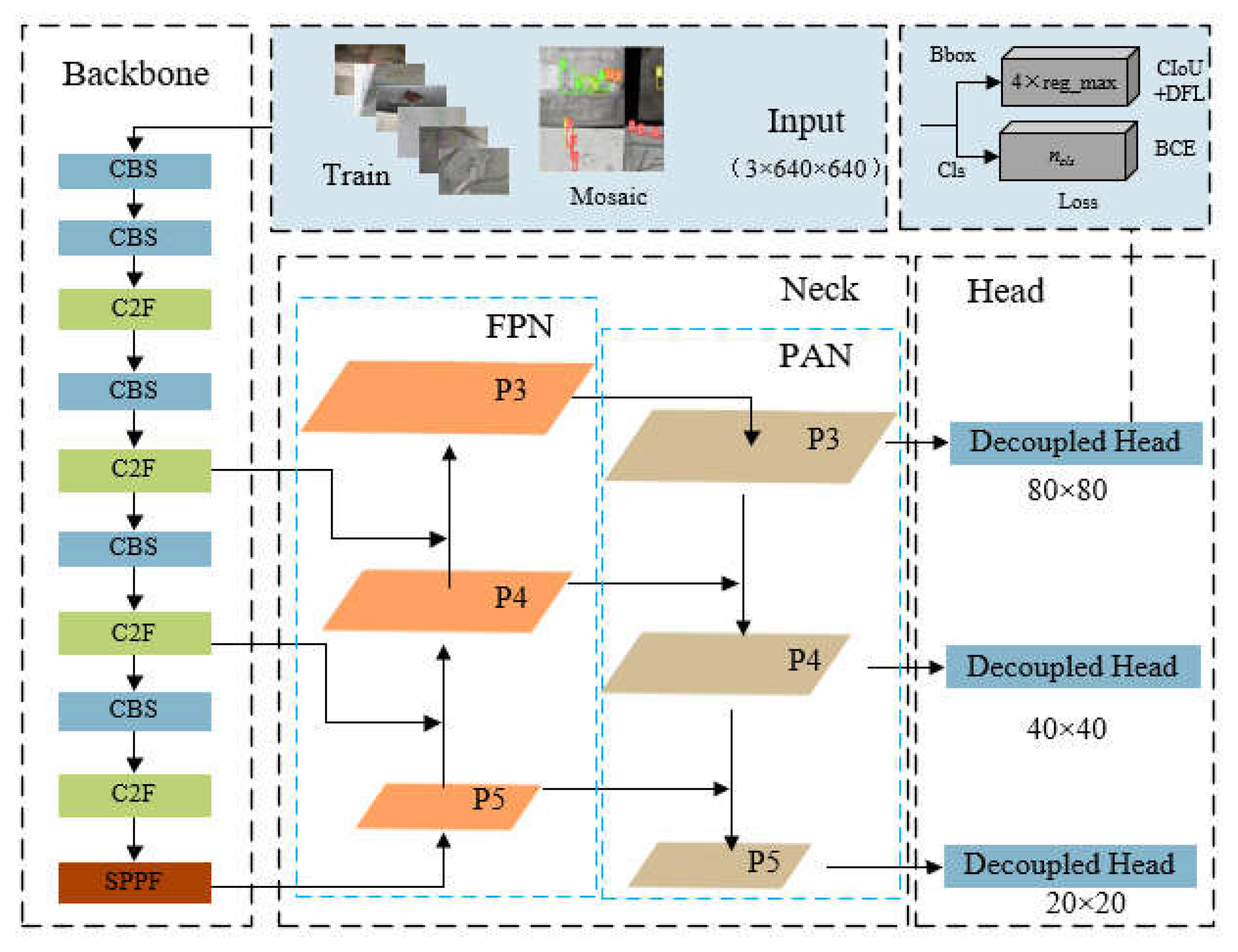
YOLOv8s was introduced in 2023 as the latest version of YOLO, which supporting image classification, object detection, and instance segmentation tasks. The model structure consists of three main components: backbone, neck, and head, as shown in
Figure 1. The received training data are pre-processed using mosaic data augmentation before entering the backbone network for feature extraction. Then, the backbone outputs three feature maps of different scales to the neck structure for bidirectional feature fusion. Finally, the head uses convolutional layers to scale the fused feature maps, producing outputs at three different scales.
The backbone network consists of CBS, C2F, and SPPF modules [
27], where the CBS module is primarily used to extract features from the input image, the C2F module retains lightweight properties while capturing richer gradient flow information, and the SPPF module employs spatial pyramid pooling by serially computing three MaxPool2d operations with 5×5 convolutional kernels. The optimisations made in this paper focus on this component, further information of the YOLOv8s can be found in the reference [
21].
3. DAC-YOLO Method Construction
3.1. Multi-Branch Coordinate Attention
Critical information about objects may be obscured by noise, image backgrounds, and uneven lighting due to complex, blurry, and poorly lit environments. Therefore, enhancing the positional information of features is of significant challenge. To address this issue, attention mechanisms [
28] have been introduced in recent years. Among these methods, the Coordinate Attention Mechanism (CAM) [
29] effectively enhances the extraction of structural information about objects by using two one-dimensional average pooling operations to aggregate the feature maps vertically and horizontally into two separate orientation-aware feature maps, which are subsequently encoded into an attention tensor containing orientation-position information, and ultimately decomposed into a pair of attention maps that are both orientation- and position-aware.
Although CAM is effective in capturing long-range dependencies in local spatial information, it overlooks the global dependencies necessary for understanding spatial features. To address this limitation, a global context perception module is introduced into the CAM aiming to help the network acquire global information by considering the overall context comprehensively. This results in more precise and comprehensive image representations for processing tasks. Additionally, by optimizing attention weights for direction awareness, position sensitivity, and global perception, the network can selectively focus on key areas of the target, significantly improving coordinate localization accuracy.
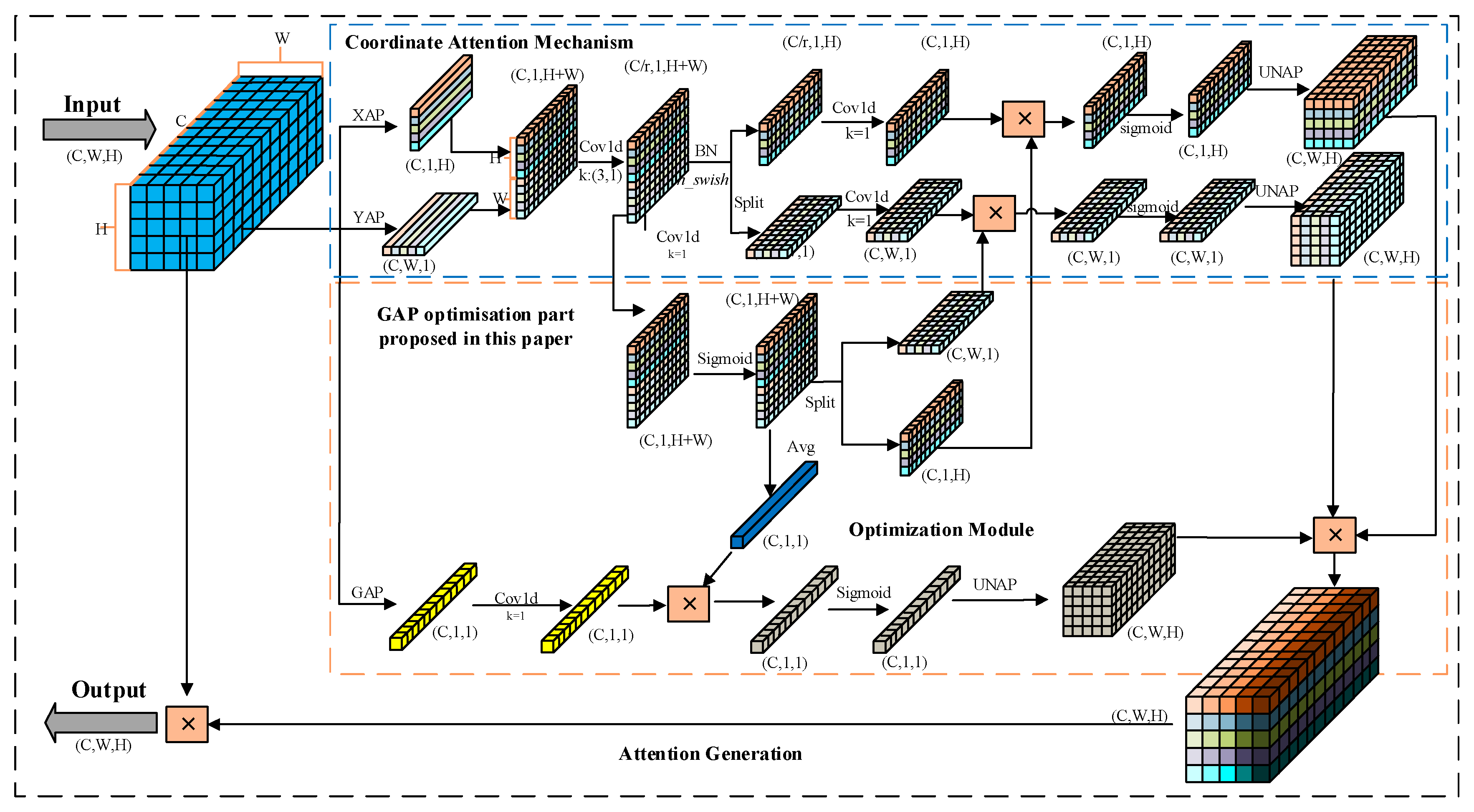
Step 1: In the information embedding phase, each channel of the input feature map X is encoded using two spatial range pooling kernels: (H, 1) and (1, W) to embed coordinate information. The kernels operate along the horizontal (width W) and vertical (height H) coordinates, respectively.
Where h and w represent the height and width of the current input feature map, respectively. c denotes the current input feature map’s channel. denotes the output of channel c at height h, and denotes the output of channel c at width w.
The global information is additionally embedded in CAM by encoding each channel of the input feature map X through global average pooling (GAP).
Where represents the global information output of channel c.
Step 2: At the coordinated and global attention generation phase, the aggregated feature maps
and
generated from Equation (1) are firstly concatenated, and then a 3×1 convolution operation is applied for information fusion, compressing feature channels. After batch normalization and non-linear activation functions, the intermediate feature map is split along the spatial dimension into two independent tensors
and
. Subsequently, two 1×1 convolutions
and
are used to transform
and
into tensors with the same number of channels as the input X. Furthermore, to fully utilize the expressive representation of the aggregated feature maps and accurately highlight the regions of interest, a feature map optimization module is proposed. This involves passing the intermediate feature map f through a 1×1 convolutional transformation function F1 to adjust the number of channels. After applying a non-linear activation function and a sigmoid function, a feature map optimization weight matrix
is obtained. The optimization weight matrix is then split along the spatial dimension into independent weights
and
for the vertical and horizontal directions, respectively. Finally, the two independent weights
and
are applied to the corresponding tensors, and after passing through a sigmoid function, the outputs
and
are expanded and used as attention weights.
Where [·,·] represents the concatenation operation along the spatial dimension. denotes the 3×1 convolution transformation function, represents the non-linear activation function hard_swish. f represents the intermediate feature map with horizontal and vertical spatial information, where . r is the reduction ratio, taken as 16. Fh and Fw represent 1×1 convolution operations in the vertical and horizontal directions, respectively. and represent intermediate feature maps in the vertical and horizontal directions, where and . σ denotes the sigmoid activation function. represents the feature map optimization weight matrix. and represent optimization weights in the vertical and horizontal directions, respectively. and represent attention weights in the vertical and horizontal directions, respectively.
For global attention generation, the global information feature map generated from Equation (2) is multiplied element-wise by the average-weighted optimization weight matrix
. Subsequently, the result passes through a sigmoid function to obtain the global attention weights
.
Where represents the 1×1 convolution transformation function. represents the mean function. represents the intermediate feature map with global information, where. represents the feature map optimization weight matrix. represents the global attention weights.
The attention weights
g are calculated by multiplying the vertical and horizontal direction attention weights with the global attention weights.
Where represents the attention weight at channel c. represents the vertical direction attention weight at channel c. represents the horizontal direction attention weight at channel c. represents the global attention weight at channel c.
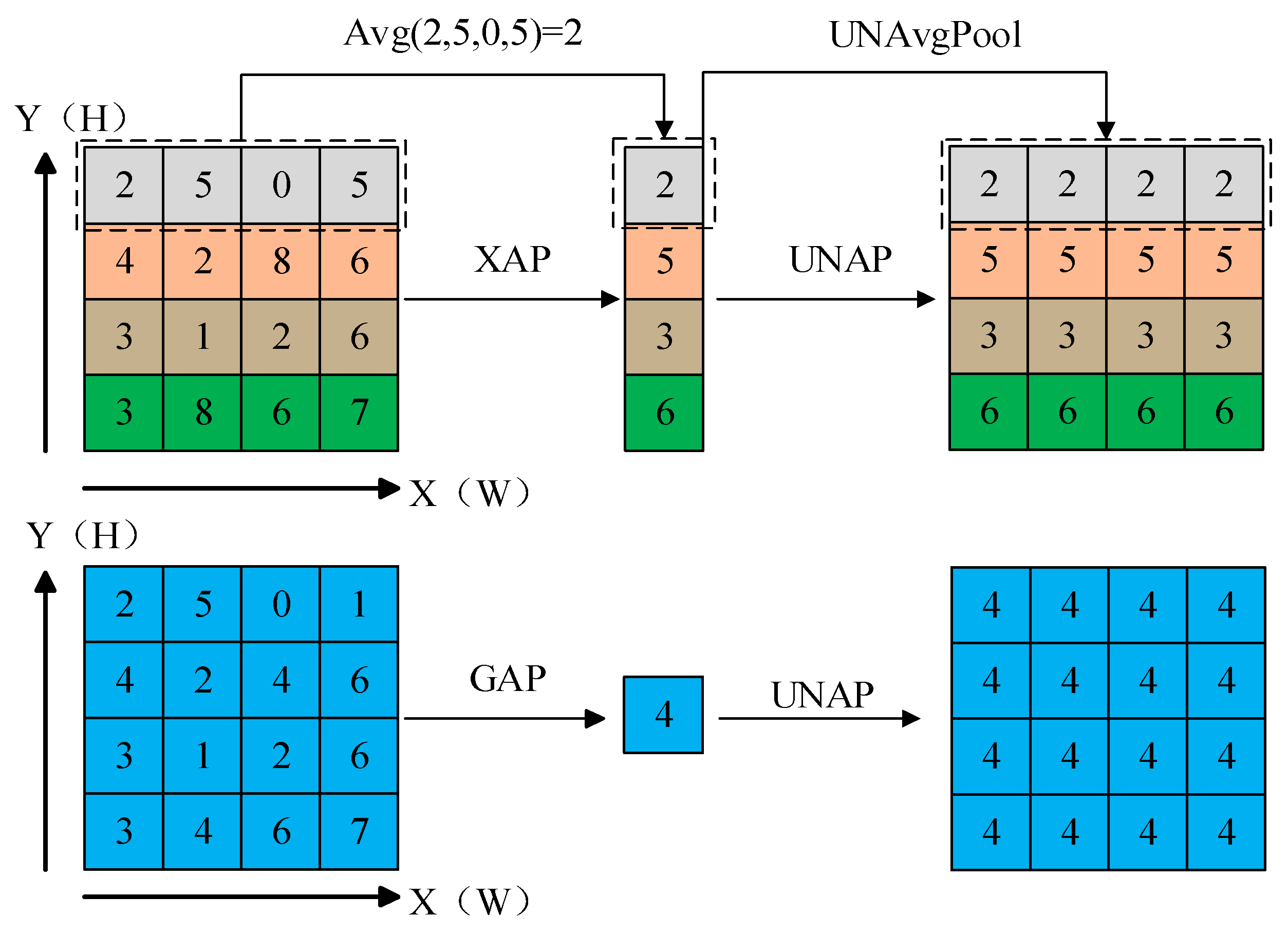
It computes the average of all elements within each feature map of the input, resulting in a feature map with a size of 1 × 1. When direct multiplication or addition operations are needed on the original input, Reverse Average Pooling (UNAP) can be used to expand the feature map to the desired size. The specific pooling operations are illustrated in
Figure 2.
The Multi-branch Coordinate Attention (MBCA) mechanism is established with the two steps above, introducing global-level information and optimizes the perception of specific target positions at the local level.
3.2. Deformable Convolution Based on MBCA
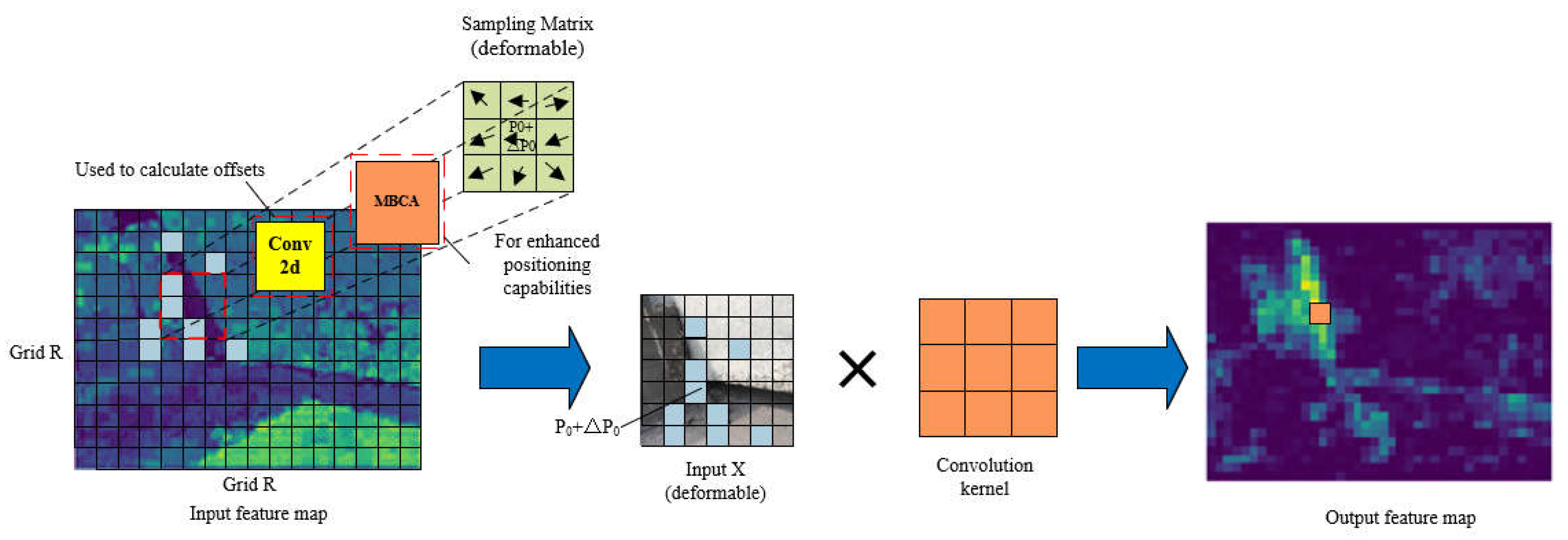
The features of the image become more complex and irregular due to weak texture or lighting changes on the target surface in the detection of weak texture areas and uneven reflection areas, making fixed receptive field kernel insufficient to adapt complex features. To address this issue, Deformable Convolution (DCNv2) [
30] is applied to learn the offset and modulation parameters for each pixel for better adjusting to the sampling position of the convolution kernel and adapting to different image structures and texture features.
For each position
p0 in the output feature map y, the deformable convolution structure is defined as follows:
Where the grid R defines the size and expansion rate of the receptive field. For a receptive field of size 3×3 and a dilation rate of 1, . p0 corresponds to mapping each point of the output feature map y to the center of the convolution kernel, and then mapping it to the coordinates in the input feature map x; pn represents the relative coordinates in R for p0. ω(·) denotes the sampling point weight, and x (·) denotes the mapping from coordinates in the input feature map x to feature vectors. The offset , and the modulation parameter lies within [0, 1].
The offsets Δ
pn and modulation parameters ∆
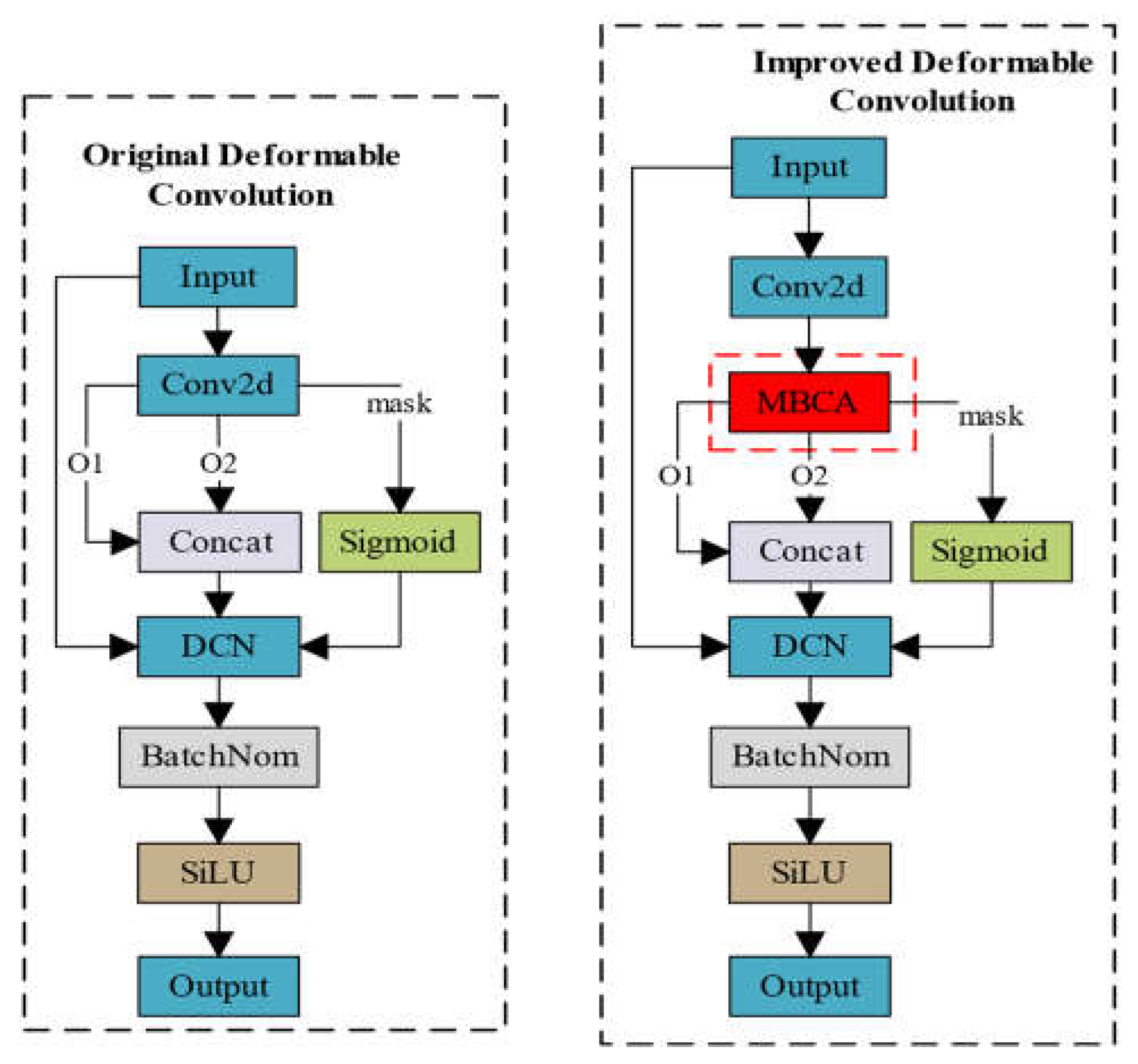
mn of deformable convolution are obtained by applying a separate standard convolution layer on the same input feature map, which results in insufficient spatial support range. As a consequence, the effective receptive field of foreground nodes and the prominent region constrained by errors may include background areas irrelevant to detection. The proposed Multi-Branch Coordinate Attention (MBCA) is embedded during the process of generating offsets Δ
pn and modulation parameters ∆
mn, which is named MBCADC, to further enhance the ability of deformable convolution DCNV2 in manipulating spatial support regions, as illustrated in
Figure 4.
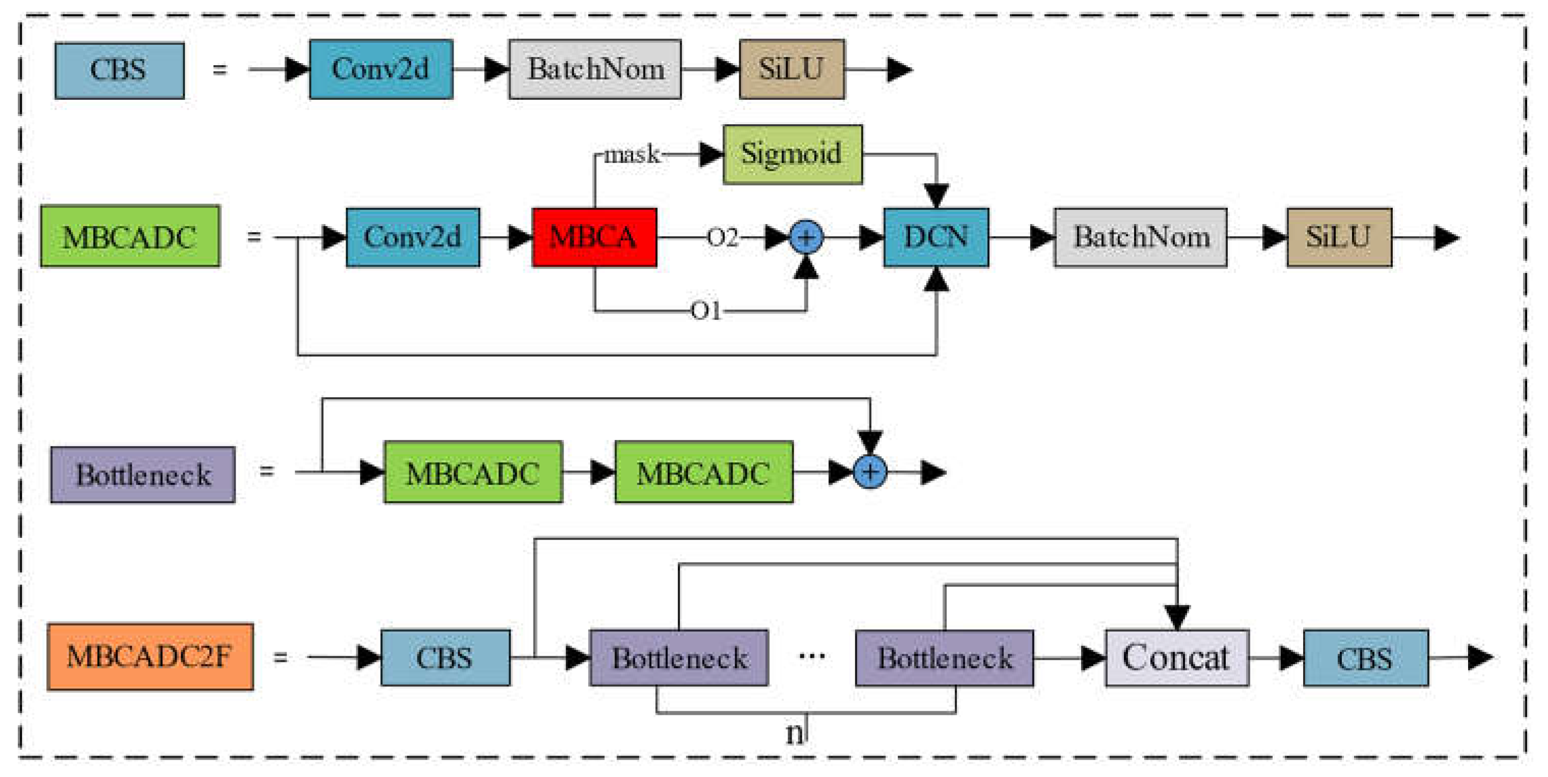
The MBCADC module consists of a Conv2d, an MBCA Attention, a DCN, a BatchNorm2d, and a SiLU activation function, where o1 and o2 represent learned offsets in the x and y coordinate directions, respectively, and mask denotes the sampling weights at different positions. The structure of the deformable convolution MBCADC is defined as follows:
Where g represents the attention weights generated by the Multi-Branch Coordinate Attention (MBCA).
Figure 5 illustrates the process of MBCADC deformable convolution. From
Figure 5, it can be observed that the sampling matrix of deformable convolution is non-fixed and deformable, with the offsets determined by algorithms that can better learn the geometric properties of the objects to be detected.
3.3. MBCADC2F Module
The MBCAC2F module is an improvement over the YOLOv8s backbone network’s C2F module, integrating the Multi-Branch Coordinate Attention Deformable Convolution (MBCADC) module. This module comprises two CBS modules and n Bottleneck modules, where the Bottleneck module contains a residual structure with two MBCADC modules, as illustrated in
Figure 6. By learning the parameters of deformable convolution, the model can dynamically adjust the sampling positions of the convolution kernel based on the actual shape and positional information of the target, allowing for more precise capture of target features.
3.4. Deformable Convolutional Net-Attention-YOLO Object Detection Network
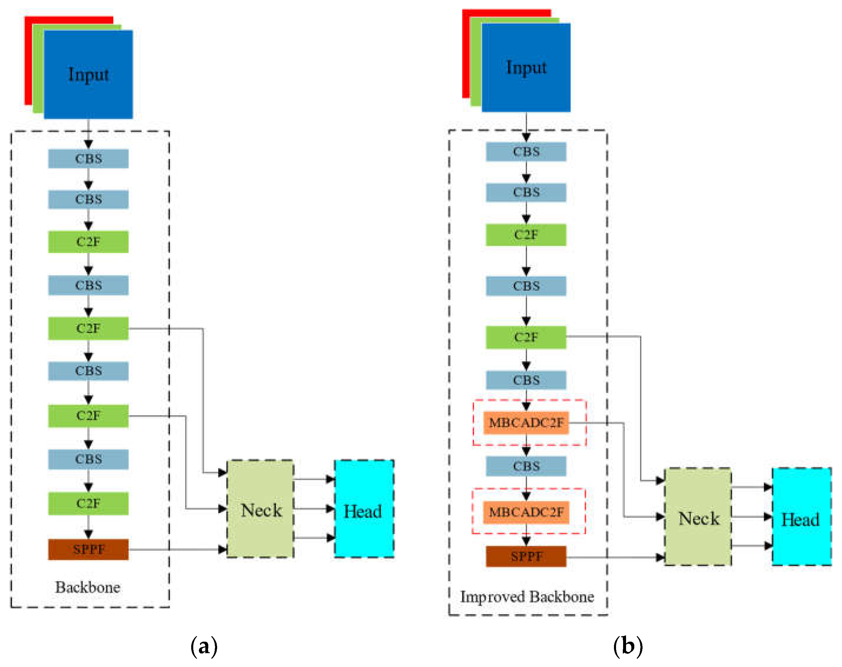
The Deformable Convolutional Net-Attention-YOLO (DCA-YOLO) algorithm improves upon the YOLOv8s baseline model by modifying the backbone network. The neck and head structures of the DCA-YOLO model remain the same as those of the baseline model. The model’s overall structure is illustrated in
Figure 8. The DCA-YOLO backbone network comprises 5 CBS modules, 2 C2F modules, 2 MBCADC2F modules, and 1 SPPF module. The structures of modules such as CBS, C2F, and SPPF in the MBCADC2F module are identical to those of the corresponding modules in the YOLOv8s baseline model. Each Bottleneck unit in the MBCADC2F module contains a residual connection structure with 2 MBCADC modules.
4. Example Verification
4.1. Experimental Dataset
We created a dataset of apparent damages on concrete bridges, consisting of 4794 images. Domain experts annotated the dataset, which we use to evaluate the effectiveness of the proposed method in identifying apparent damages on concrete bridges. According to the regulations of China’s road and bridge maintenance standards and inspection standards, concrete apparent damages are classified into seven types: cracks, spalling, honeycombing, exposed reinforcement, water seepage, and voids. The constructed dataset includes at least one type of damage in each image. Augmenting the dataset enhances its diversity and richness, making the model’s detection more effective [
31]. The original dataset was randomly divided into training, validation, and testing sets with a ratio of 8:1:1. Data augmentation techniques, such as flipping, rotation, and HSV enhancement, were then applied to the divided dataset. The dataset sizes are as follows: 14528 images in the training set, 1816 images in the validation set, and 1816 images in the testing set.
Table 1 shows the statistical results of the number of annotated boxes for each type of damage.
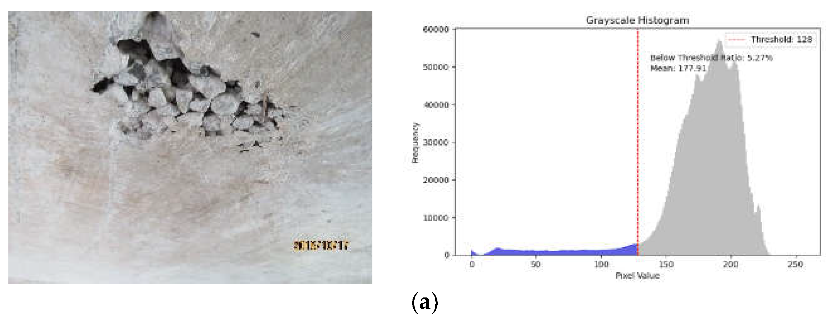
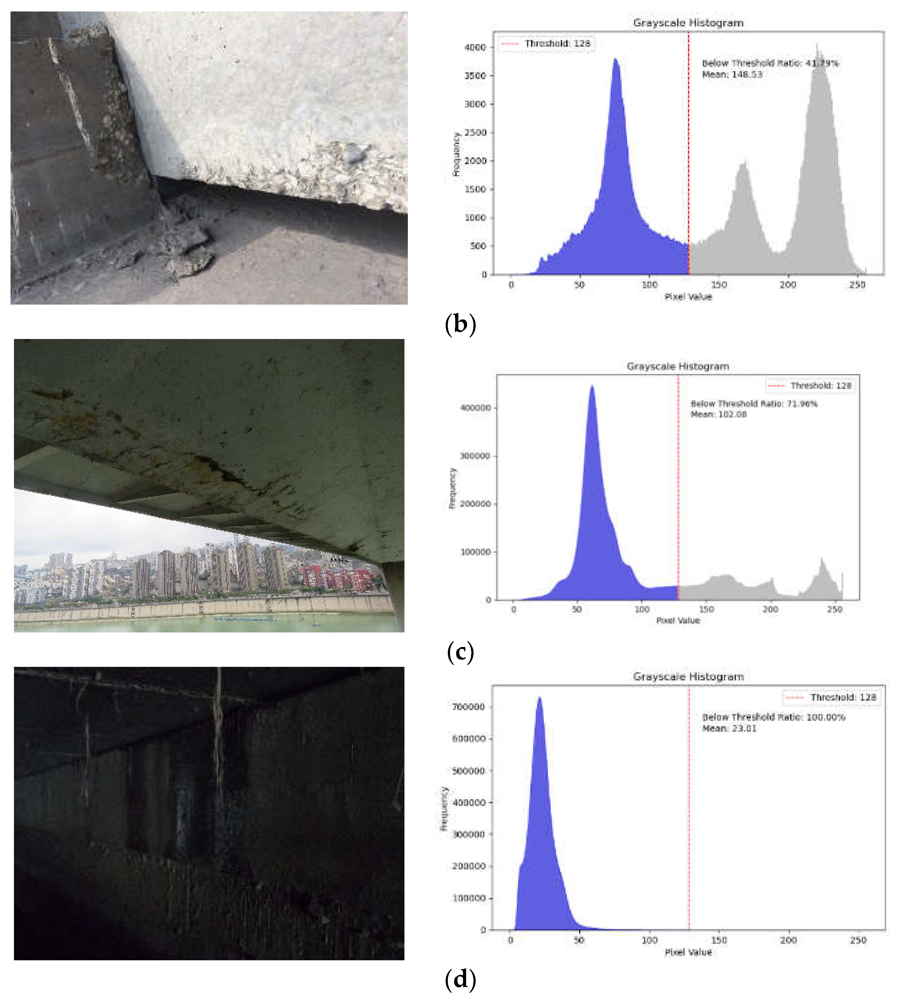
The images of the bridge’s apparent damages collected in the experimental dataset are affected by the lighting environment, resulting in variations in image quality. Statistical analysis was conducted on the grayscale histograms of the images, which allowed for the categorization of the images into four lighting conditions:
(1) Well-lit images: that exhibit high clarity and rich details. The histogram of the grayscale image displays an unimodal distribution, with grayscale values primarily ranging from 150 to 250. The average grayscale value of the image is greater than 170.
(2) Partial shadow or occlusion images: the grayscale distribution is complex, with areas of varying brightness. The histogram of the grayscale image displays a bimodal distribution, with grayscale values primarily ranging from 50-100 and 150-250. The image’s average grayscale value is approximately 150.
(3) Low-lighting images: overall low brightness can result in blurry or confusing areas in the apparent damaged regions. The grayscale histogram of the image displays an unimodal distribution, with grayscale values primarily distributed between 50 and 100. The image’s average grayscale value is approximately 100.
(4) Dark-lighting images: overall low brightness can make it challenging to distinguish details of the apparent damages. The image’s grayscale histogram displays an unimodal distribution, with grayscale values ranging from 0 to 50. The average grayscale value of the image is below 30.
Figure 8 shows the grayscale histograms for the four distinct illumination images.
Table 2 presents a statistical study of the number of Well-lit images, Partial shadow or occlusion images, Low-lighting images and Dark-lighting images.
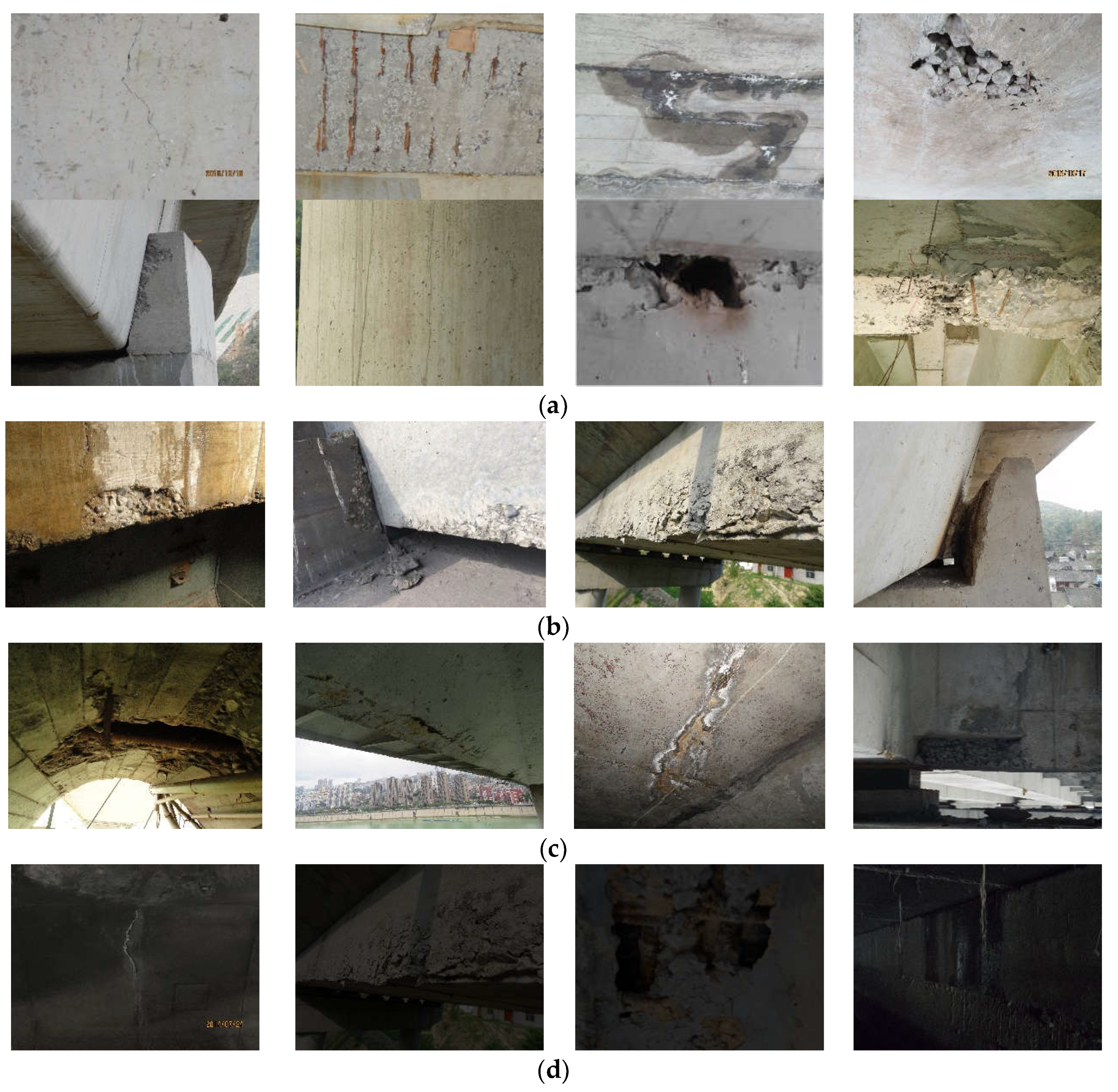
Figure 9 illustrates some examples of picture data.
4.2. Environmental Design and Evaluation Metrics
The computer hardware setup includes an Intel Core i5-13600K CPU, 48GB of RAM, and an NVIDIA GeForce RTX4070 with a 12282Mib GPU. The experimental environment consists of Windows 10, CUDA 11.8, PyTorch 2.0.1, and Python 3.8.18. The training parameter settings have an initial learning rate of 0.01, with a learning rate strategy that employs cosine annealing. The number of training epochs is set to 300, with an initial input size of the model at 640×640 and a batch size of 16. The optimization algorithm used is SG [
32], with the loss function being cross-entropy. To prevent overfitting, early stopping criteria are employed. The network training is halted if the validation accuracy does not improve after 50 epochs.
To evaluate the model’s detection performance for 7 types of visual diseases, we use precision (P), recall (R), mean average precision (mAP), model parameters quantity (Parameters), floating-point operations (FLOPs), and frames per second (FPS) as evaluation metrics.
4.3. Experimental Results and Analysis
4.3.1. Ablation Experiment
To further validate the effectiveness of the proposed improvements in terms of the number and placement of different enhancement modules, ablation experiments, and quantitative and qualitative analysis were performed using the generated dataset in the same experimental environment to evaluate the benefits of key components in the model. Among them, “MBCA” refers to the addition of MBCA attention after the last layer of the backbone network SPPF; “DCNv2” refers to the replacement of the bottleneck in the C2F module of the eighth layer of the backbone network with deformable convolution DCNv; “Proposed method” refers to replacing the C2F module of the sixth and the eighth layer of the backbone network with the MBCADC2F module proposed in this paper. The experimental results are presented in
Table 3.
A comparison of the data in the table shows that the MBCA attention mechanism proposed in this study did not significantly increase the number of network parameters and model complexity while improving the model’s mAP0.5 value by 0.5%. Deformable convolution DCNv2 was able to reduce the model complexity and improve the model mAP0.5 without significantly increasing the model parameter count. The method proposed in this paper achieved the best experimental results, with only a 0.2M increase in model parameters compared to the baseline model. Furthermore, floating point operations were reduced by 1.2G, precision increased by 1.8%, recall improved by 3.4%, and mAP0.5 and mAP0.5:0.95 increased by 2.0% and 4.4% respectively. In addition, the model’s speed of detection increased by 3.5/f·s-1.
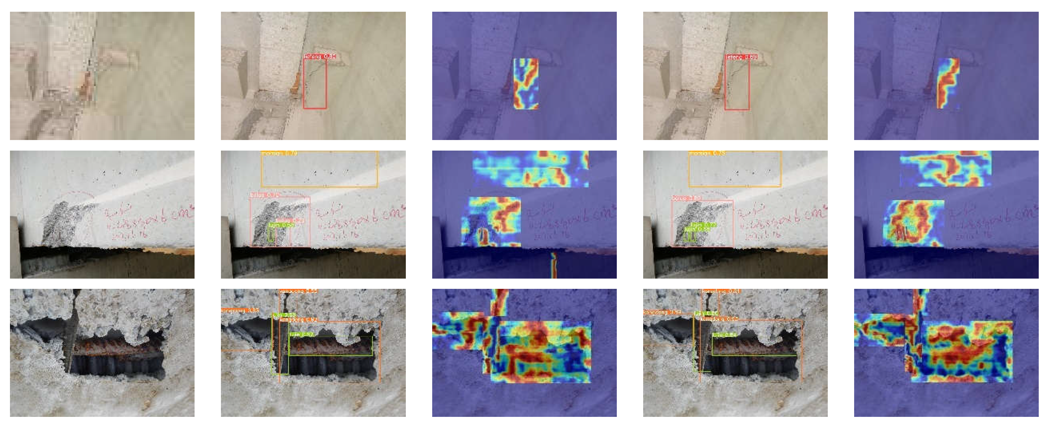
Figure 10 shows a comparison between the test results and the heatmap analysis of the baseline model and the proposed method on Well-lit images. The heatmaps were generated using the Grad-CAM method [
33]. It shows that both models achieve good detection results for all seven types of surface defects on images with good lighting conditions. The proposed method detects all defects, while the baseline model misses a small exposed rebar (fourth-row image). Furthermore, the accuracy of the detection results obtained by the proposed method is consistently higher than that of the baseline model. A comparison of the heatmaps shows that the proposed method provides a better representation, with the heatmaps better conforming to the shape of the target. These results indicate that the proposed method is effective in improving detection accuracy for images with good lighting conditions.
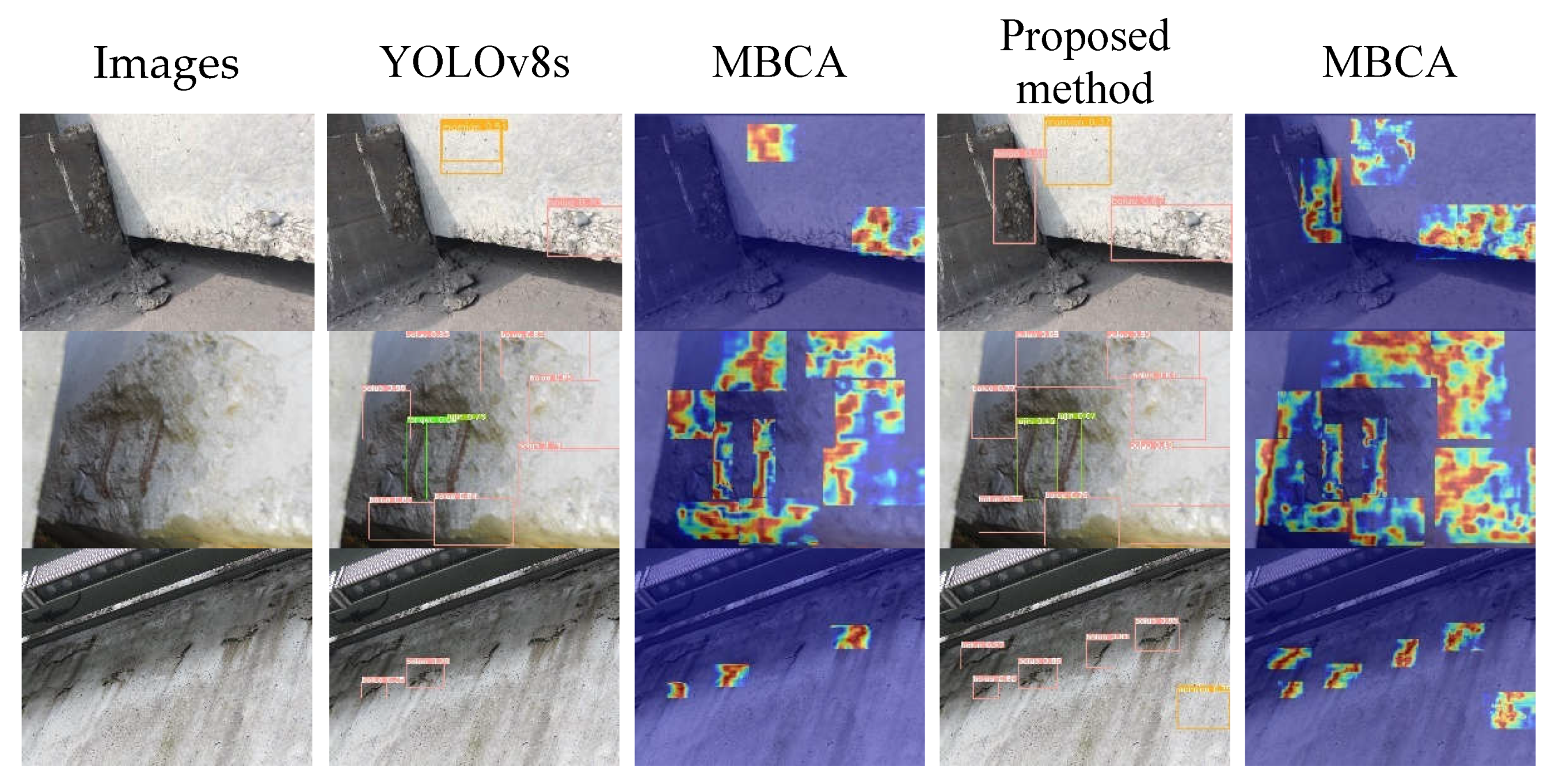
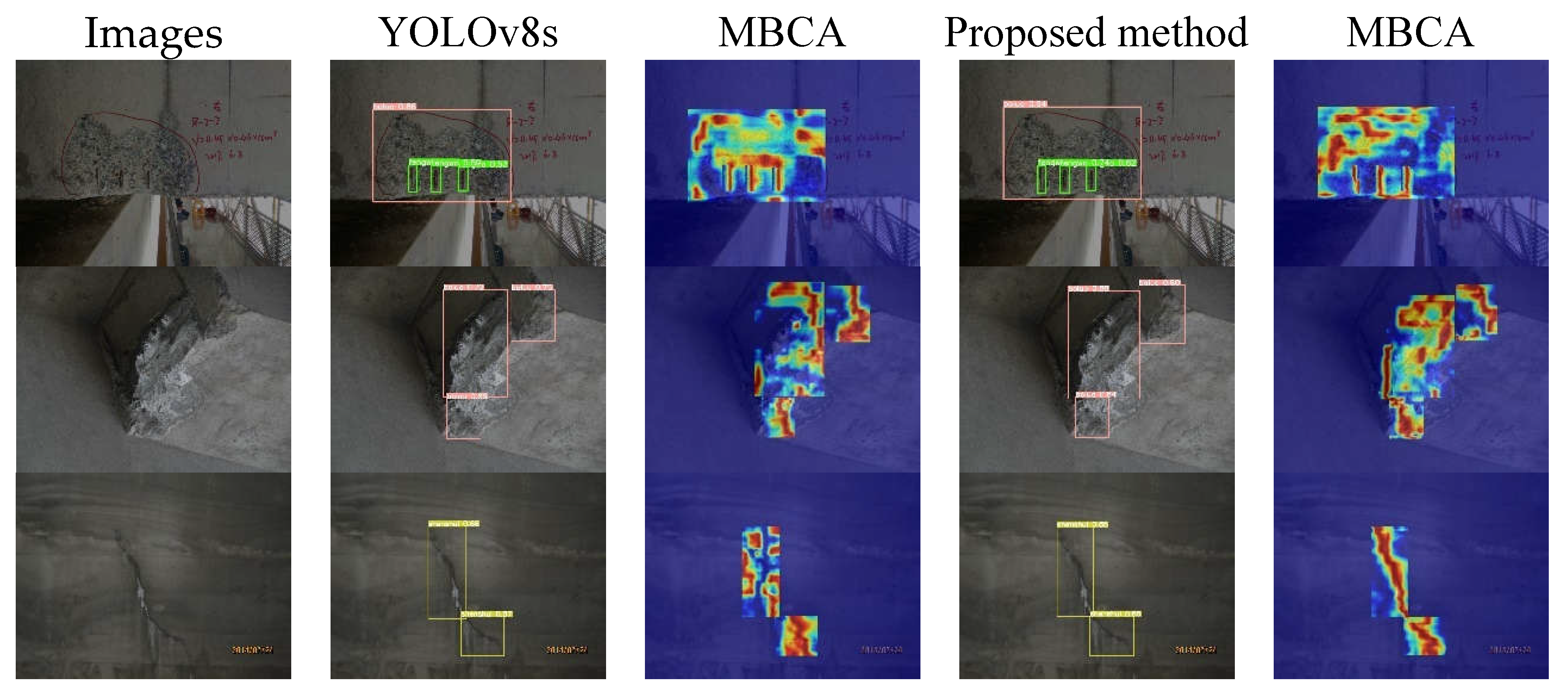
Figure 11 shows a comparison between the test results and the heatmap analysis of the baseline model and the proposed method on images with partial shadows or occlusions. It can be seen that the proposed method achieves better detection results than the baseline model on images with partial shadows or occlusions. In images with partial shadows or occlusions, there are areas of varying brightness due to significant changes in illumination and uneven reflections on the target surface. The baseline model with fixed geometric structures of convolutional kernels is not effective in capturing the spatial information of the target in these regions. The proposed method uses deformable convolution based on multi-branch coordinate attention, which allows the model to dynamically adjust the sampling positions of the convolutional kernels according to the actual shape and position information of the target. A comparison of the heatmaps shows that the proposed method provides a better representation, with the heatmaps focusing more on the edge features of the target, which can effectively reduces the rates of missed detections and false positives in images with partial shadows or occlusions.
Figure 12 shows the comparison between the tester and the heat map analysis of the baseline model and the proposed method. It can be seen that both the baseline model and the proposed method can detect the class and location of defects in the image under low-light conditions. However, the detection accuracy of the proposed method is higher compared to the baseline model. As a result, the texture of the target region in the image may be relatively weak, resulting in lower detection accuracy of the model. A comparison of the heat maps shows that the proposed method can effectively highlight the features of the defective region, thus improving the detection accuracy of the model.
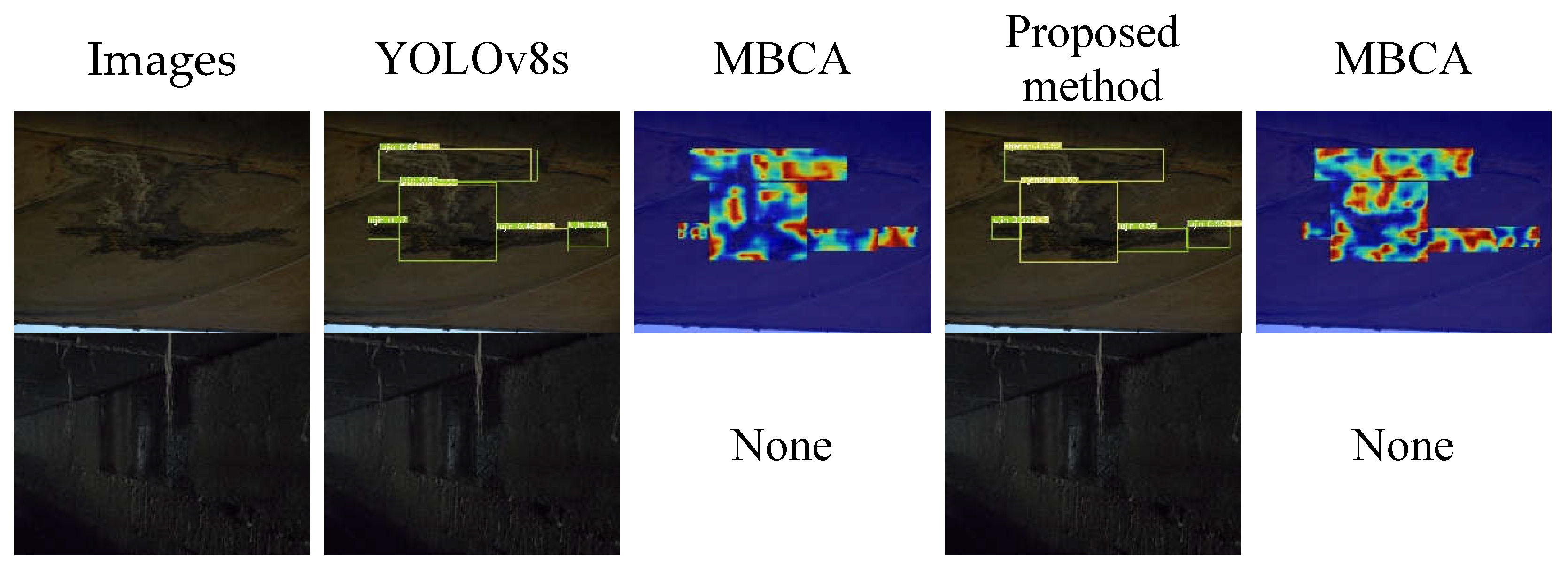
Figure 13 illustrates a comparison between the test results and heatmap analysis of the baseline model and the proposed method on images with dark lighting conditions. From
Figure 13, it can be seen that both the baseline model and the proposed method perform poorly on images with dark lighting conditions. In images with dark lighting conditions, the overall brightness is low, making it difficult to detect surface defect details. The models fail to learn useful information from the images, resulting in incorrect target category detection or no defect detection.
In summary, the proposed method effectively improves the detection accuracy of images with good lighting conditions and those with poor lighting conditions, effectively mitigating the problems of missed detections and false positives.
4.3.2. Comparison Experiment of Different Detection Algorithms
Considering the real-time performance and accuracy requirements for concrete bridge surface defect detection tasks, the two-stage object detection models of the RCNN series and the outdated SSD models were not included in the comparative experiments. Instead, more widely used and advanced models from the YOLO series were selected as the benchmark models. The results are presented in
Table 4.
Comparing the data in
Table 4, it is evident that the model proposed in this paper exhibits more effective performance in terms of detection accuracy compared to the current state-of-the-art (SOTA) models. The mAP0.5 value is improved by 11.1%, 0.7%, and 1.7% compared to the classical YOLOv3-tiny, YOLOv5s, and YOLOv6s models, respectively. Compared to the baseline model YOLOv8s, the proposed model achieves a 2.0% and 4.4% improvement in average precision (mAP0.5 and mAP0.5:0.95, respectively), a 3.4% increase in recall rate, an increase of 3.5/f·s-1 in detection speed, and a reduction in model complexity by 1.2G. These results demonstrate that the proposed model has better detection performance in concrete bridge surface defect detection.
5. Conclusion
A novel object detection algorithm called DAC-YOLO based on multi-channel attention mechanisms and deformable convolutions is proposed to address the problems of missed detections and false positives in regions with insufficient illumination, complex backgrounds, and weak surface textures on concrete bridge surfaces. The main conclusions can be drawn from this work as follows:
(1) The Multi-Branch Coordinate Attention (MBCA) is presented by introducing global information branch in the coordinate attention mechanism to obtain spatial coordinate information and global information simultaneously, improving the accuracy of coordinate information in the attention mechanism.
(2) Deformable convolution is introduced to improve the adaptability of the convolution kernel, and MBCA mechanism is embedded to enhance the coordinate localisation ability for better adaptation to different image structures and texture features.
(3) Validating the proposed framework on a self-constructed concrete surface defect dataset, effectively improves the detection accuracy of regions with significant light variations, uneven reflections, and weak textures without increasing the complexity, thus mitigating the problems of missed detections and false alarms.
Author Contributions
Conceptualization, Tijun Li; methodology, Tijun Li; software, Tijun Li; validation, Tijun Li and Shuaishuai Tan; formal analysis, Gang Liu; investigation, Gang Liu; resources, Gang Liu; data curation, Tijun Li; writing—original draft preparation, Tijun Li; writing—review and editing, Shuaishuai Tan; visualization, Tijun Li; supervision, Gang Liu; project administration, Gang Liu; funding acquisition, Gang Liu. All authors have read and agreed to the published version of the manuscript.
Funding
This research was funded by the National Natural Science Foundation of China (52221002, 52078084), Fundamental Research Funds for the Central Universities (2023CDJKYJH093), and the 111 project of the Ministry of Education and the Bureau of Foreign Experts of China (Grant No. B18062).
Data Availability Statement
The data used in this paper can be obtained through the corresponding author
Conflicts of Interest
The authors declare no conflicts of interest.
References
- Xing, S.-L.; Ye, J.-S.; Jiang, C.-Y. Review the study on typical diseases and design countermeasures of China concrete curved bridges. 2010 International Conference on Mechanic Automation and Control Engineering. IEEE, 2010: 4805-4808.
- NI F, ZHANG J, CHEN Z. Zernike-moment measurement of thin-crack width in images enabled by dual-scale deep learning. Computer-Aided Civil and Infrastructure Engineering, 2019, 34(5): 367-384.
- Y. LeCun, Y. Y. LeCun, Y. Bengio, G. Hinton, Deep learning, Nature. 521 (2015) 436–444.
- Cha, Y.; Choi, W.; Büyüköztürk, O. Deep Learning-Based Crack Damage Detection Using Convolutional Neural Networks. Comput. Aided Civil Infrastruct. Eng 2017, 32, 361–378. [Google Scholar] [CrossRef]
- Ni, F.; Zhang, J.; Chen, Z. Pixel-level crack delineation in images with convolutional feature fusion. Struct. Control. Heal. Monit. 2018, 26, e2286. [Google Scholar] [CrossRef]
- Dung, C.V.; Anh, L.D. Autonomous concrete crack detection using deep fully convolutional neural network. Autom. Constr. 2018, 99, 52–58. [Google Scholar] [CrossRef]
- Ali, R.; Cha, Y.-J. Subsurface damage detection of a steel bridge using deep learning and uncooled micro-bolometer. Constr. Build. Mater. 2019, 226, 376–387. [Google Scholar] [CrossRef]
- Girshick, R.; Donahue, J.; Darrell, T.; Malik, J. Rich Feature Hierarchies for Accurate Object Detection and Semantic Segmentation[C]. 2014 IEEE Conference on Computer Vision and Pattern Recognition, Columbus, OH, USA. 2014. [CrossRef]
- GIRSHICK, R. Fast R-CNN. 2015 IEEE International Conference on Computer Vision (ICCV), Santiago, Chile. 2015.
- Ren, S.; He, K.; Girshick, R.; Sun, J. Faster R-CNN: Towards real-time object detection with region proposal networks. IEEE Transactions on Pattern Analysis and Machine Intelligence, 2017: 1137-1149.
- HE K, GKIOXARI G, DOLLAR P, et al. Mask R-CNN. IEEE Transactions on Pattern Analysis and Machine Intelligence, 2020: 386-397.
- REDMON J, DIVVALA S, GIRSHICK R, et al. You Only Look Once: Unified, Real-Time Object Detection. 2016 IEEE Conference on Computer Vision and Pattern Recognition (CVPR), Las Vegas, NV, USA. 2016.
- LIU W, ANGUELOV D, ERHAN D, et al. SSD: Single Shot MultiBox Detector[M]. Computer Vision – ECCV 2016, Lecture Notes in Computer Science. 2016: 21-37.
- REDMON J, FARHADI A. YOLO9000: Better, Faster, Stronger. 2017 IEEE Conference on Computer Vision and Pattern Recognition (CVPR), Honolulu, HI. 2017.
- REDMON J, FARHADI A. YOLOv3: An Incremental Improvement. arXiv: Computer Vision and Pattern Recognition, 2018.
- BOCHKOVSKIY A, WANG C Y, LIAO H Y. YOLOv4: Optimal Speed and Accuracy of Object Detection. Cornell University - arXiv preprint arXiv, 2020.
- Ultralytics YOLOv5. Available online: https://github.com/ultralytics/yolov5.
- LI C, LI L, JIANG H, et al. YOLOv6: A Single-Stage Object Detection Framework for Industrial Applications. 2022.
- WANG C Y, BOCHKOVSKIY A, LIAO H Y. YOLOv7: Trainable bag-of-freebies sets new state-of-the-art for real-time object detectors. arXiv preprint arXiv:2207.02696 , 2022.
- GE Z, LIU S, WANG F, et al. YOLOX: Exceeding YOLO Series in 2021. 2021.
- Ultralytics YOLOV8. Available online: https://github.com/ultralytics/ultralytics.
- Feng, C.; Zhong, Y.; Gao, Y.; Scott, M.R.; Huang, W. TOOD: Task-aligned One-stage Object Detection. International Conference on Computer Vision, 2021.
- ZHANG X B, LUO Z P, JI J H, et al. Intelligent Surface Cracks Detection in Bridges Using Deep Neural Network. International Journal of Structural Stability and Dynamics, 2023-07-06.
- Yu, Z. YOLO V5s-based Deep Learning Approach for Concrete Cracks Detection. SHS Web Conf. 2022, 144, 03015. [Google Scholar] [CrossRef]
- Jin, Q.; Han, Q.; Su, N.; Wu, Y.; Han, Y. A Deep Learning and Morphological Method for Concrete Cracks Detection. J. Circuits, Syst. Comput. 2023, 32. [Google Scholar] [CrossRef]
- Wu, Y.; Han, Q.; Jin, Q.; Li, J.; Zhang, Y. LCA-YOLOv8-Seg: An Improved Lightweight YOLOv8-Seg for Real-Time Pixel-Level Crack Detection of Dams and Bridges. Appl. Sci. 2023, 13, 10583. [Google Scholar] [CrossRef]
- Elfwing, S.; Uchibe, E.; Doya, K. Sigmoid-weighted linear units for neural network function approximation in reinforcement learning. Neural Networks 2018, 107, 3–11. [Google Scholar] [CrossRef] [PubMed]
- TSOTSOS J, K. A Computational Perspective on Visual Attention[M]. The MIT Presse Books. 2011.
- HOU Q, ZHOU D, FENG J. Coordinate Attention for Efficient Mobile Network Design. 2021 IEEE/CVF Conference on Computer Vision and Pattern Recognition (CVPR), Nashville, TN, USA. 2021.
- DAI J, QI H, XIONG Y, et al. Deformable Convolutional Networks. 2017 IEEE International Conference on Computer Vision (ICCV), Venice. 2017.
- ZHANG J, QIAN S, TAN C. Automated bridge surface crack detection and segmentation using computer vision-based deep learning model[J/OL]. Engineering Applications of Artificial Intelligence, 2022: 105225.
- ROBBINS H, MONRO S. A Stochastic Approximation Method[J/OL]. The Annals of Mathematical Statistics: 400-407.
- SELVARAJU R R, COGSWELL M, DAS A, et al. Grad-CAM: Visual Explanations from Deep Networks via Gradient-based Localization[J/OL]. International Journal of Computer Vision, 2020: 336-359.
Figure 1.
Network structure diagram of YOLOv8s.
Figure 1.
Network structure diagram of YOLOv8s.
Figure 2.
Schematic diagram of XAP, GAP and UNAP.
Figure 2.
Schematic diagram of XAP, GAP and UNAP.
Figure 3.
The principle of the Multi-Branch Coordinate Attention (MBCA) algorithm.
Figure 3.
The principle of the Multi-Branch Coordinate Attention (MBCA) algorithm.
Figure 4.
Structure of Original Deformable Convolution (DCNv2) and Improved Deformable Convolution (MBCADC).
Figure 4.
Structure of Original Deformable Convolution (DCNv2) and Improved Deformable Convolution (MBCADC).
Figure 5.
Process of MBCADC Deformable Convolution.
Figure 5.
Process of MBCADC Deformable Convolution.
Figure 6.
The structure of the MBCADC2F module.
Figure 6.
The structure of the MBCADC2F module.
Figure 7.
Original Yolov8s and proposed DCA-YOLO overall framework. (a) Original Yolov8s overall framework; (b) Proposed DCA-YOLO overall framework.
Figure 7.
Original Yolov8s and proposed DCA-YOLO overall framework. (a) Original Yolov8s overall framework; (b) Proposed DCA-YOLO overall framework.
Figure 8.
Images and grayscale histograms captured under varying lighting conditions. (a) Well-lit image and its gray histogram; (b) Partial shadow or occlusion image and its gray histogram; (c) Low-lighting image and its gray histogram; (d) Dark-lighting image and its gray histogram.
Figure 8.
Images and grayscale histograms captured under varying lighting conditions. (a) Well-lit image and its gray histogram; (b) Partial shadow or occlusion image and its gray histogram; (c) Low-lighting image and its gray histogram; (d) Dark-lighting image and its gray histogram.
Figure 9.
Images used for the experimental evaluation. (a)Example Images of Well-lit images; (b) Example Images of Partial shadow or occlusion images; (c) Example Images of Low-lighting images; (d ) Example Images of Dark-lighting images.
Figure 9.
Images used for the experimental evaluation. (a)Example Images of Well-lit images; (b) Example Images of Partial shadow or occlusion images; (c) Example Images of Low-lighting images; (d ) Example Images of Dark-lighting images.
Figure 10.
Detection results and heat maps of seven types of disease in well-lit images.
Figure 10.
Detection results and heat maps of seven types of disease in well-lit images.
Figure 11.
Detection results and heat maps of partially shaded or occluded image lesions.
Figure 11.
Detection results and heat maps of partially shaded or occluded image lesions.
Figure 12.
Detection results and thermograms of disease in low-light images.
Figure 12.
Detection results and thermograms of disease in low-light images.
Figure 13.
Detection results and thermograms of dark light image diseases.
Figure 13.
Detection results and thermograms of dark light image diseases.
Table 1.
Number of Labels for Each Disease in the Dataset.
Table 1.
Number of Labels for Each Disease in the Dataset.
| Labels(diseases) |
Number |
Labels(diseases) |
Number |
| liefeng(crack) |
17636 |
shenshui(seepage) |
9244 |
| boluo(spalling) |
11875 |
fengwo(comb surface) |
8330 |
| kongdong(cavity) |
7082 |
lujin(steel exposed) |
6584 |
| mamian(pockmark) |
8274 |
|
|
Table 2.
Summary of Image Quantities Under Different Illumination Conditions.
Table 2.
Summary of Image Quantities Under Different Illumination Conditions.
| Data set |
Well-lit
images |
Partial shadow or occlusion images |
Low-lighting
images |
Dark-lighting
images |
total |
| Train |
6697 |
1798 |
2608 |
3425 |
14528 |
| Val |
923 |
239 |
298 |
356 |
1816 |
| Test |
876 |
225 |
326 |
389 |
1816 |
Table 3.
Results of ablation experiments.
Table 3.
Results of ablation experiments.
| Model |
Parameters/M |
FLOPs/G |
FPS/f·s-1
|
P/% |
R/% |
mAP0.5/% |
mAP0.5:0.95/% |
| YOLOv8s |
11.1 |
28.7 |
70.9 |
89.1 |
82.0 |
87.4 |
68.9 |
| +MBCA |
11.2 |
28.7 |
68.9 |
90.2 |
82.7 |
87.9 |
68.9 |
| +DCNv2 |
11.2 |
27.5 |
73.8 |
90.0 |
82.5 |
88.1 |
70.2 |
| proposed method |
11.3 |
27.5 |
74.4 |
91.3 |
85.4 |
89.4 |
73.3 |
Table 4.
Comparative experimental results of different network models.
Table 4.
Comparative experimental results of different network models.
| Model |
Parameters/M |
FLOPs/G |
FPS/f·s-1
|
P/% |
R/% |
mAP0.5/% |
mAP0.5:0.95/% |
| YOLOv3-tiny |
12.1 |
19.1 |
76.9 |
81.7 |
73.4 |
78.6 |
53.4 |
| YOLOv5s |
7.0 |
16.8 |
78.3 |
91.2 |
84.9 |
88.7 |
67.4 |
| YOLOv6s |
16.3 |
44.2 |
69.4 |
90.2 |
81.5 |
87.7 |
69.6 |
| YOLOv8s |
11.1 |
28.7 |
70.9 |
89.1 |
82.0 |
87.4 |
68.9 |
| Proposed method |
11.3 |
27.5 |
74.4 |
91.3 |
85.4 |
89.4 |
73.3 |
|
Disclaimer/Publisher’s Note: The statements, opinions and data contained in all publications are solely those of the individual author(s) and contributor(s) and not of MDPI and/or the editor(s). MDPI and/or the editor(s) disclaim responsibility for any injury to people or property resulting from any ideas, methods, instructions or products referred to in the content. |
© 2024 by the authors. Licensee MDPI, Basel, Switzerland. This article is an open access article distributed under the terms and conditions of the Creative Commons Attribution (CC BY) license (https://creativecommons.org/licenses/by/4.0/).
