Preprint
Article

Properties of a Pressureless Sintered 2Y-TZP Material Combining High Strength and Toughness

Altmetrics

Downloads

102

Views

48

Comments

0

A peer-reviewed article of this preprint also exists.

This version is not peer-reviewed

Submitted:

23 May 2024

Posted:

24 May 2024

You are already at the latest version

Alerts
Abstract
Yttria stabilized zirconia materials are frequently used in mechanical engineering and biomedical applications. Demanding loading conditions require materials combining a high level of strength and fracture toughness. A ready to press alumina doped 2 mol% yttria stabilized zirconia powder was shaped by axial pressing and sintering in air at 1250 - 1500 °C for 2 h. The best combination of strength and toughness value of 7.8 MPa√m. Materials sintered in the middle of the chosen temperature range combine fully density, high transformability and small grain size. Toughness measurements by direct crack length measurements delivered unrealistically high fracture toughness values.
Keywords: 
Subject: Chemistry and Materials Science  -   Materials Science and Technology

1. Introduction

Partially stabilized zirconia materials are structural ceramics which combine high strength and fracture toughness by exploiting the effect of transformation toughening (TT) [1]. TT describes a reinforcement mechanism based on the martensitic transformation of metastable tetragonal phase to stable monoclinic phase associated with volume expansion and shear. If a crack in partially stabilized zirconia is put under tensile stress, a transformation zone forms at the crack tip. As the crack expands, the transformation zone in the wake of the crack exerts compressive stress which leads to reduction of the stress intensity at the crack tip, the shear component can be accommodated by twin-like orientation of the transformed monoclinic domains [2,3]. In order to obtain a metastable tetragonal phase after sintering, zirconia has to be stabilized by addition of oxides containing aliovalent or isovalent cations which stabilize the tetragonal phase by expanding the lattice, by introduction of oxygen vacancies or both [4,5]. Today yttria is probably the technologically most important stabilizer oxide. As yttria is trivalent, yttria addition introduces oxygen vacancies to retain charge neutrality. Moreover, as Y3+ is an oversized dopant (larger than Zr4+) additional stabilization by lattice expansion is obtained. Yttria forms tetragonal and cubic solid solutions with zirconia [6]. The yttria content in yttria stabilized tetragonal zirconia polycrystals (Y-TZP) typically is 3 mol% [7]. Thermodynamically, at typical sintering temperatures of ~1400 °C this is a composition located in the t+c field which represents miscibility gap and ranges from 2.5 - 6.5 mol% Y2O3 [6]. The composition should, therefore, by rule of the lever decompose to ~20 % cubic and ~80 % tetragonal phase. However, as the powders are typically made by co-precipitation the initial distribution of yttria in zirconia is homogeneous at atomic level. Phase segregation is therefore inhibited and requires high sintering temperatures [8]. The tetragonal phase in 3Y-TZP sintered at moderate temperatures is therefore super-saturated and not very transformable. This leads to materials with high strength (> 1000 MPa) but very moderate toughness (4-6 MPa√m) [9]. In order to improve the toughness of Y-TZP made from co-precipitated powder two pathways are possible. The first is to overfire the TZP to temperatures above 1500 °C for long dwell time to trigger the phase segregation and increase the grain size of the tetragonal grains to make the material more transformable [10]. The second is to reduce the stabilizer content to a level below 2.5 mol% to obtain a more transformable tetragonal phase [11]. Both procedures face some difficulties. The first route leads to very coarse grained materials with reduced strength. At the same time these materials become very prone to degrade by low temperature degradation in presence of humidity [12]. In case of the second route it has to be considered that the critical grain size beyond which the material will transform spontaneously during cooling from sintering temperature is reduced with declining stabilizer content [13]. This requires very fine and sinterable starting powders to obtain fully dense ceramics at moderate sintering temperatures. Even more so as one may expect that low stabilizer and entirely tetragonal compositions do not profit to the same extent from solute drag of excess yttria which prevents grain growth in 3Y-TZP [8]. The concept is known for decades and is well described in literature [14]. The difficulties described above have for a long time prevented implementation of understabilized Y-TZP, as it was considered too dangerous to use for fear of spontaneous transformation. In recent years different powder producers launched new understabilized Y-TZPs (with 1.5-2 mol% Y2O3) and there are a few new studies. Innovnano’s 2Y-TZP which was produced by detonation synthesis delivered an impressive combination of strength and toughness but has disappeared from the market [15]. Tosoh’s ZGAIA 1.5Y-TZP promised extreme toughness in combination with attractive strength [16]. Recent studies by Imarouane showed that indentation toughness values were exaggerated, still a fracture toughness of 9 MPa√m combined with a strength of 1000 MPa are respectable [17]. The material is however tricky to sinter and requires high cooling rates to retain the metastable tetragonal phase [18]. In the present study a new alumina doped 2Y-TZP issued by Treibacher Industries in Austria was tested.

2. Materials and Methods

The starting material used in this study is a zirconia powder stabilized with 2 mol% of Yttria and alloyed with 0.4 wt-% of alumina, the powders was delivered as a ready to press granulate by the manufacturer (Auertec® 2Y-40A-B, Treibacher, Austria, SBET = 11.15 m2/g). The loss on ignition (correlates to binder content) was specified as 4.3 wt-%. Granules have an average diameter of 45 µm. The powder was cold pressed in a rectangular steel die of 35x35 mm² diameter (Graveurbetrieb Leonhardt, Germany) at 125 MPa pressure in a manually operated press (Paul Weber, Germany). 9 g of powder were weighed per plate which results in a sintered plate of approx. 2 mm thickness. The plates were subsequently debindered in air (1 K/min to 600 °C, 3 h dwell, Linn, Germany) and sintered in air in a dental furnace (MIHM-Vogt HT speed, Germany) at 2 K/min to 1200 °C and 1 K/min to final temperature (1250 - 1500 °C in 50 °C increments). Cooling was carried out at 12 K/min to room temperature.
The plates (4 plates per sintering temperature) were then lapped on both sides with 15 µm diamond suspension and polished on one side with 15 µm, 6 µm 3µm and 1µm diamond suspension to obtain a mirror like finish using an automatic machine (Struers Rotopol, Denmark). The plates were cut into bars with 4 mm width (Struers Accutom, Denmark) with a diamond wheel. The as cut sides were lapped with 15 µm to remove cutting induced defects, finally the edges were beveled manually using a 40 µm diamond disk.
Density of the samples was measured by buoyancy method using polished plates prior to cutting (Kern, Germany). Vickers hardness measurements HV10 (n = 5) (Bareiss, Germany) were carried out to determine the hardness and the indentation fracture resistance KDCM by direct crack length measurements. The indentation toughness was calculated according to the Niihara Palmqvist crack model [19]. For the fully dense Y-TZP samples a Young’s modulus of 210 GPa was assumed [15]. Four-point bending tests were carried out in a setup with 20 mm outer and 10 mm inner span at a crosshead speed of 0.5 mm/min (n = 12) (Zwick, Germany). Indentation strength in bending (ISB) tests were carried out in the same setup at 2.5 mm/min crosshead speed. For the ISB tests the samples were indented with 4 indents at a distance of 2 mm on the tensile side with crack parallel and perpendicular to the sides. The indented side was placed within the inner span and the residual strength was measured. Placing dummy indentations was necessary due to the inhomogeneity of the crack pattern in order to obtain at least one valid indentation per bar. The ISB toughness KISB was then calculated using the model of Chantikul [20]. It is known from literature that in understabilized Y-TZP materials transformation zones around the indents may cause crack trapping effects, which lead to overestimated toughness values [21] Hence, a modified SIGB (stable indentation crack growth in bending) test according to Dransmann was applied [22]. In order to suppress transformation and obtain starter cracks exceeding the uplifted zone around the crack, HV10 Vickers indents were introduced at elevated temperature (250 - 300 °C). The samples were then progressively loaded at 5mm/min and the crack growth was measured after each loading step. A detailed description of the SIGB test is given by Benzaid [23].
The phase composition of as fired samples without preparation was measured by XRD according to the protocol of Toraya [24]. The phase composition was also determined in fracture surfaces in order to determine the transformability and the transformation zone size according to Kosmac [25]. The fourth order peaks in the 72-75° 2θ range were studied to obtain tetragonality values and confirm absence of cubic phase.
The transformation toughness values were calculated according to McMeeking and Evans assuming a transformation efficiency of 0.27 (predominantly dilational transformation) [26].
SEM images were taken from polished and thermally etched samples (10 K/min to 1150°C, 10 dwell in air) in order to determine the grain size [27] and identify possible thermal transformation effects.
The tensile sides of fractured bars were checked by optical microscopy for formation of transformation bands which would indicate transformation related failure [28].

3. Results

3.1. Density and Mechanical Properties

The density ρ of the TZP samples sintered at different temperatures is shown in Figure 1. Evidently sintering at 1250 °C is not sufficient (relative density 97.9 %) to obtain fully dense material. At sintering temperature ≥ 1300 °C the obtained materials are practically fully dense (99.3 - 99.7 % assuming a theoretical density of 6.1 g/cm³).
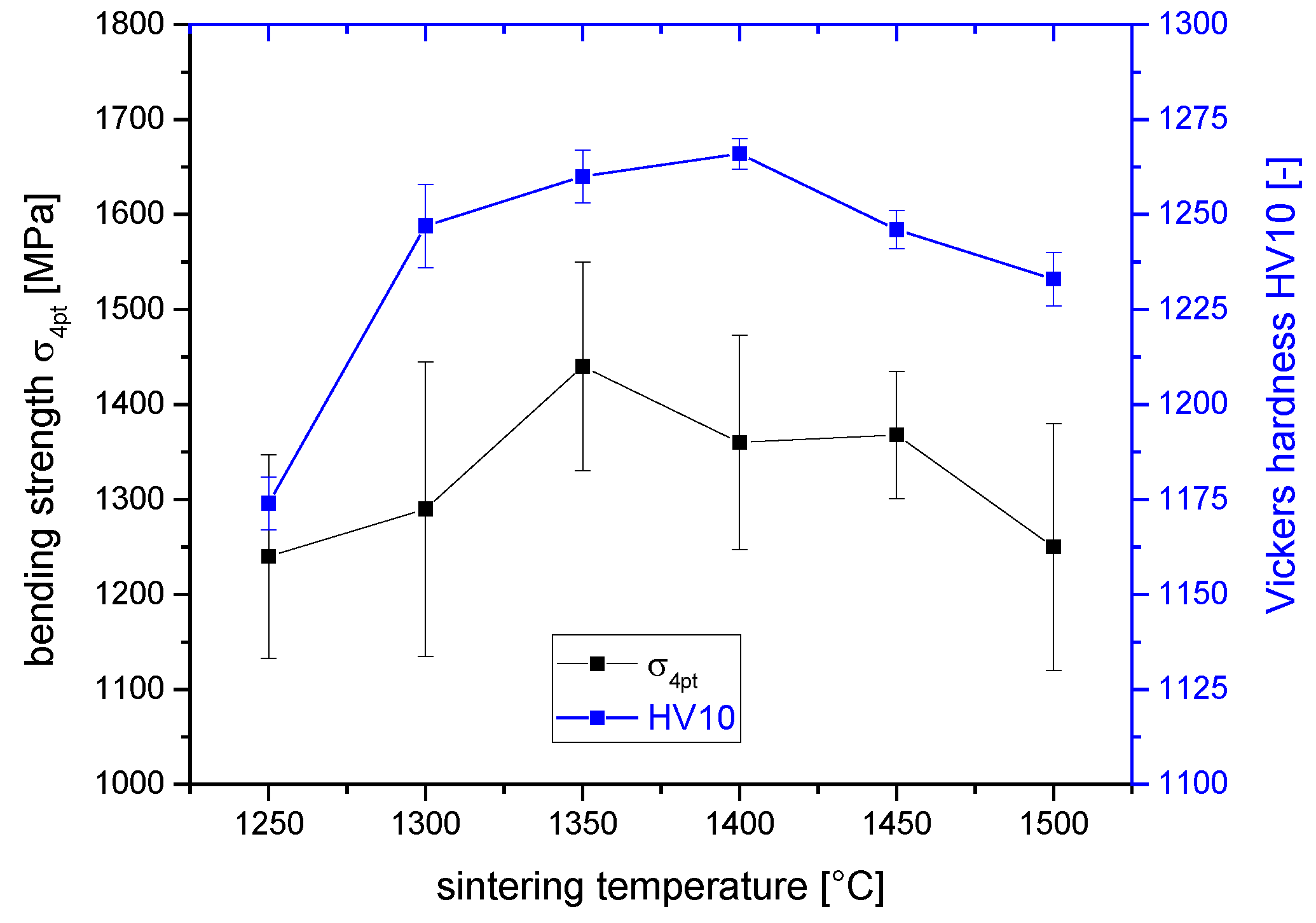
Figure 2 shows the Vickers hardness HV10 and the bending strength σ4pt of the TZPs sintered at different temperatures. The Vickers hardness shows a strong correlation to the density values. The hardness increases from 1175 HV10 to 1250 HV10 between 1250 -1300 °C. Then the hardness further increases until 1400 °C, the slight reduction in hardness at even higher temperatures is probably related to increasing grain size. All samples reach average bending strength values > 1200 °C. The strength maximum is obtained at 1350 °C with 1440 ± 110 MPa.
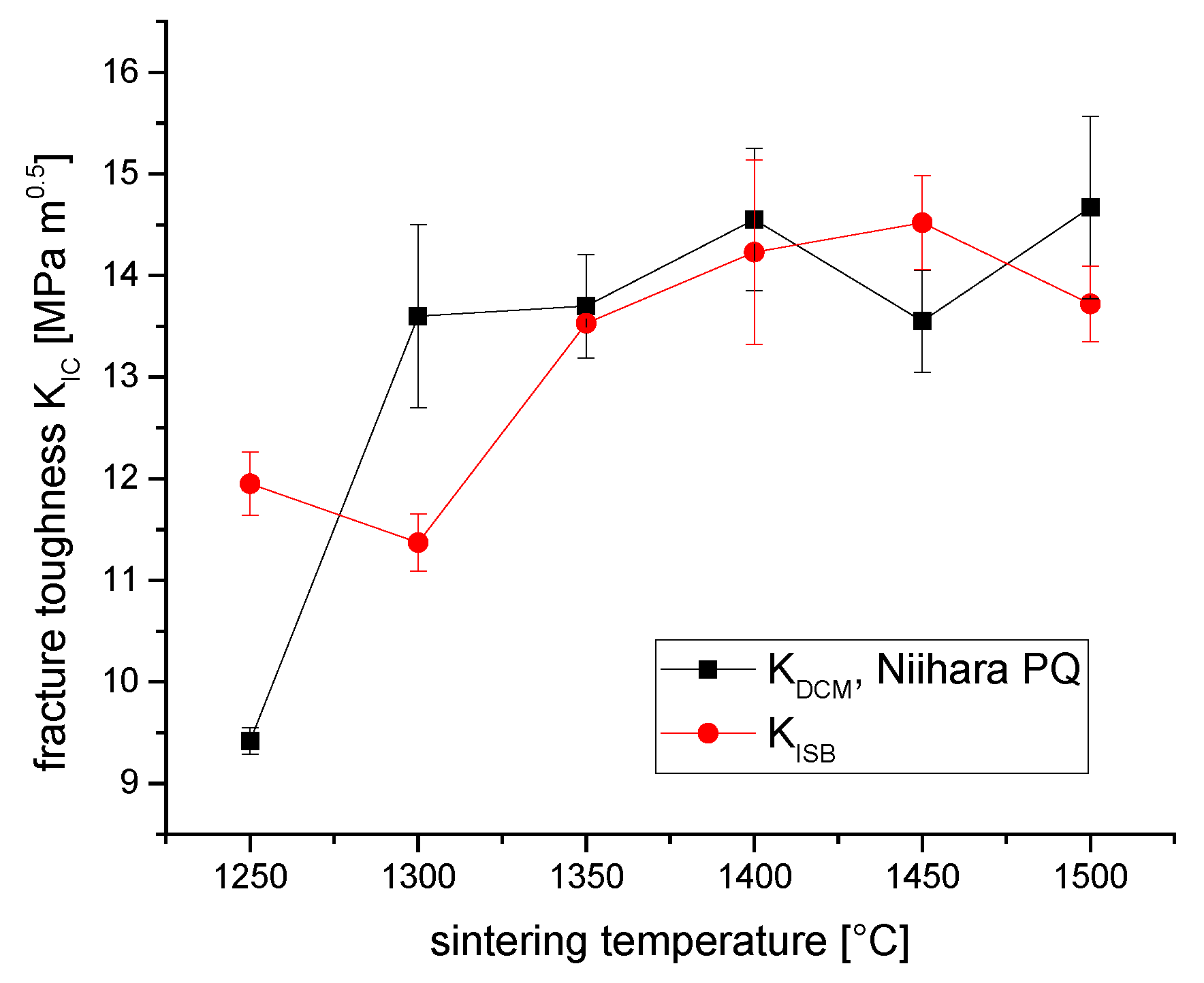
Figure 3 shows the fracture toughness values KDCM obtained by direct crack length measurement and indentation strength in bending KISB derived from residual strength values of samples indented at ambient temperature. Note: Both calculation methods require a value for the Youngs modulus E, E was assumed as 210 GPa for all samples except the sample sintered at 1250 °C which was not dense (assumed value 200 GPa).
The toughness level determined by both testing protocols are comparable and extremely high. Maximum values of 13-15 MPa√m were measured at sintering temperatures between 1300 °C and 1500 °C. These results correlate very well with indentation toughness data obtained by Billovits for the same material [29] and Matsui for ZGAIA 1.5Y-TZP [16]. Realistically the strength-toughness correlations published by Swain [30] raise some doubts about the correctness of these indentation based toughness values. With the given strength of 1200 - 1440 MPa (here the values can be considered reliable) the corresponding toughness can be achieved either on the defect size related branch of the curve at 6 MPa√m or on the transformation dominated side at 8 MPa√m (note that Swain’s data are indentation toughness data, strength data are from 3pt measurements). Moreover the observed crack patterns which are frequently incomplete are a clear indication of trapping effects. As the ISB test is based on the assumption of semicircular crack geometries (geometry factor Y = 1.27) a correction factor needs to be introduced. Dransmann experimentally determined a value of Y = 1.08 for 3Y-TZP [22]. In the present case of even tougher 2Y-TZP we may estimate Y = 0.95. This would reduce the uncorrected maximum ISB-toughness values by 25 % to corrected values of ~10.5 MPa√m.
The following graph (Figure 4) shows the fracture toughness values determined from the strongest survivors in the SIGB test using samples which were indented at elevated temperature. Note that no extrapolation to infinite crack lengths was carried out which may lead to a slight underestimation of toughness [22,23]. The sample sintered at 1500 °C was thermally too instable and did not survive the heating procedure. The indentation at 250 °C increases the crack length 2c (from crack tip to crack tip in a HV10 indent) from approximately 0.14 µm to 0.18 µm. In fact, as expected due to larger starting cracks and suppression of transformation induced crack trapping, the warm-indented samples fail at stress levels of 500-540 MPa. ISB samples indented at ambient temperature reach residual strength levels of 1000 MPa. The toughness levels by SIGB range from 5.5 MPa√m to 7.8 MPa√m. Such values seem reasonable with respect to Swains reference data [30]. The maximum toughness is achieved at 1350°C sintering temperature. The toughness dip at 1300°C is probably related to the incomplete densification at 1250°C. The presence of porosity in the 1250°C sample reduces the elastic constraint and facilitates transformation. Moreover, pores may stop cracks. The same toughness minimum is seen in the ISB-toughness values (Figure 3).

3.2. Microstructure

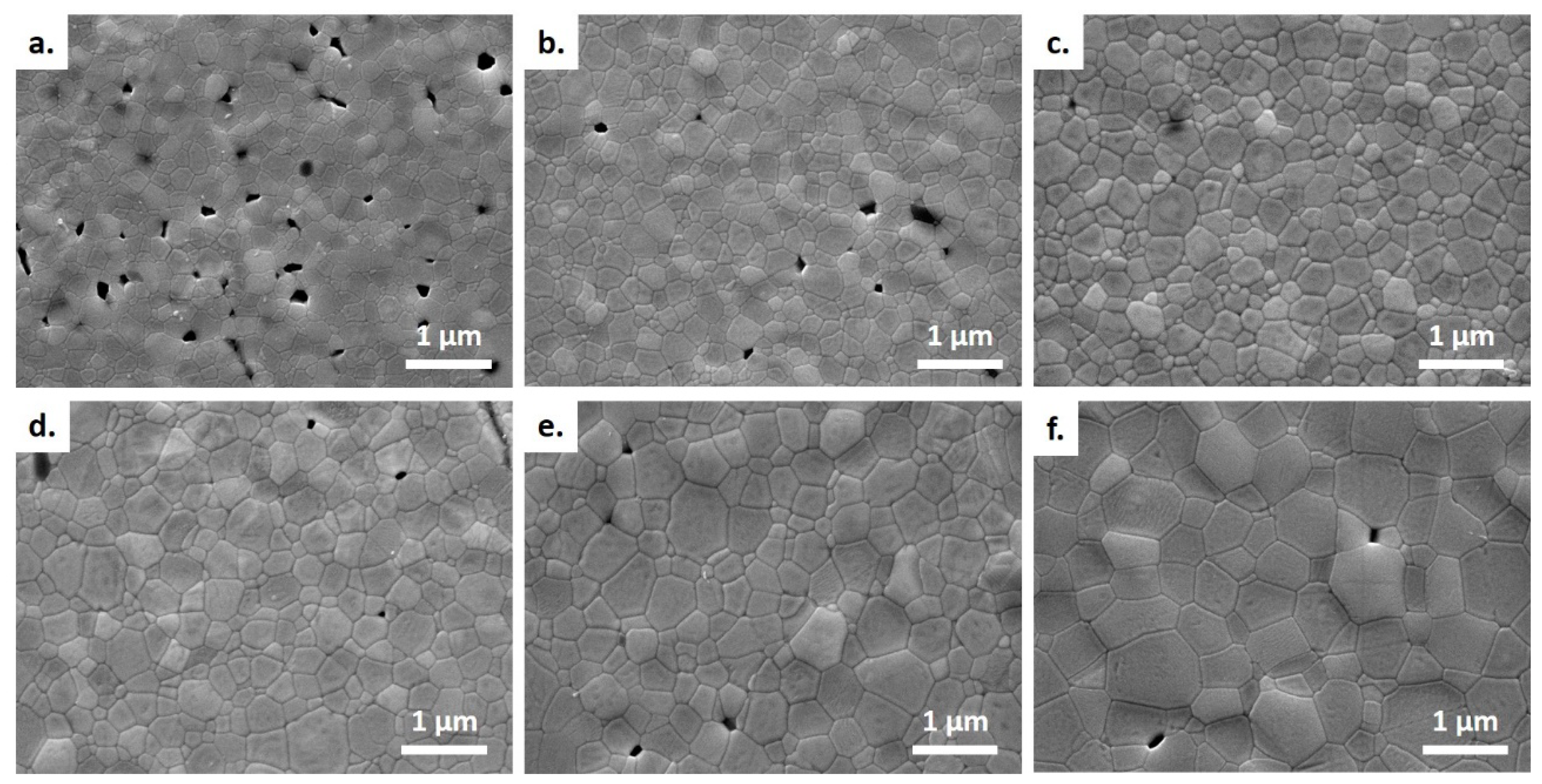
Figure 5 shows the microstructure of polished and thermally etched samples sintered at different sintering temperatures. Considerable porosity is visible in the sample sintered at 1250 °C/2 h. At higher sintering temperatures porosity is significantly reduced. Some isolated pores are visible even at the highest sintering temperature. Microstructure images are in accord with measured densities (Figure 1). The uneven surface structure especially at sintering temperatures > 1400 °C may indicate a certain degree of t-m phase transformation which is associated with volume expansion.
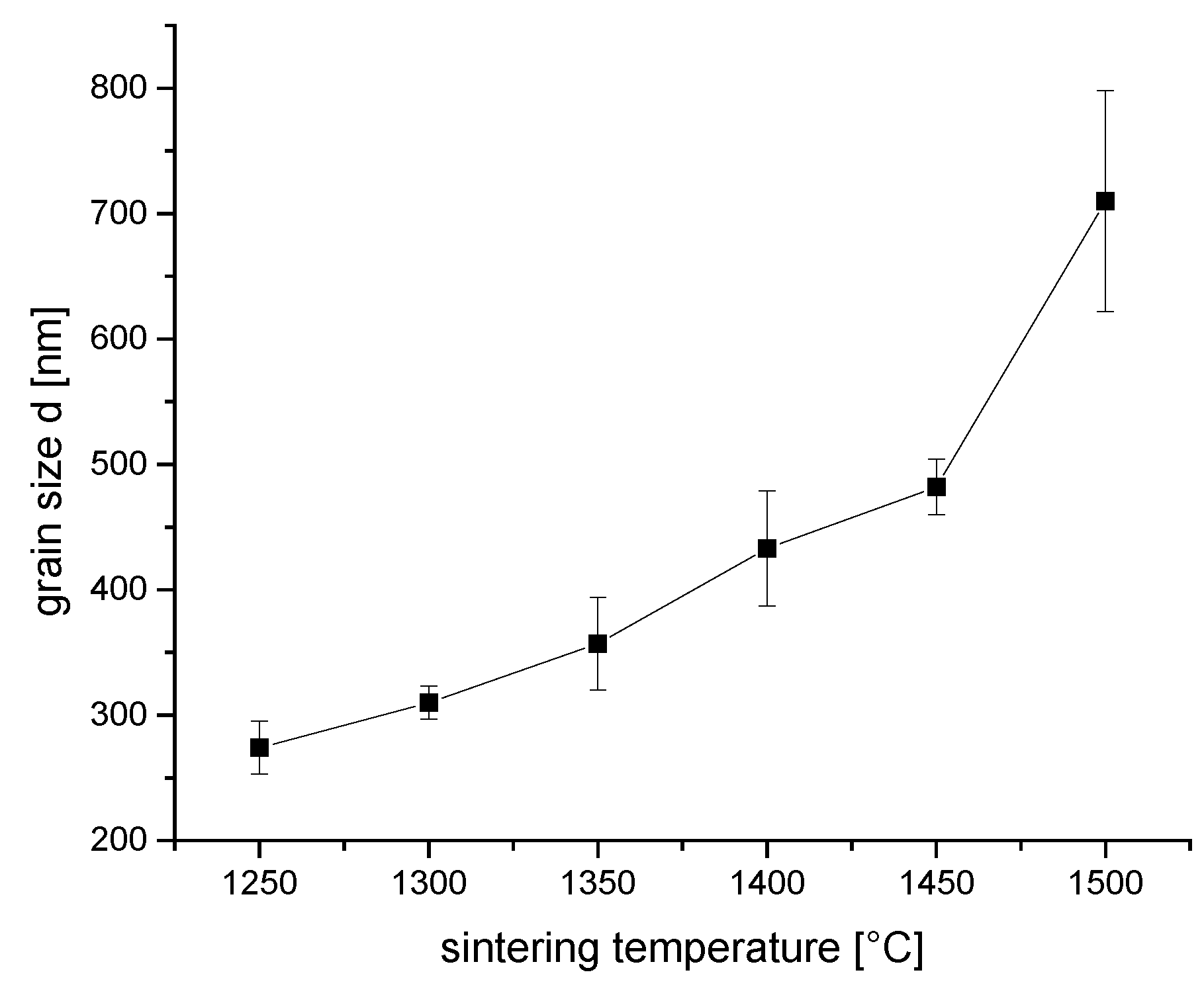
Figure 6 shows the evolution of average grain size with sintering temperature. As expected grain size increases with sintering temperature. Considering a maximum grain size of 400 nm as required for high strength dental applications (three or more element bridges) according to EN 6872, the sintering temperature should be limited to 1350-1400 °C.

3.3. Phase Composition and Transformation toughening Effect

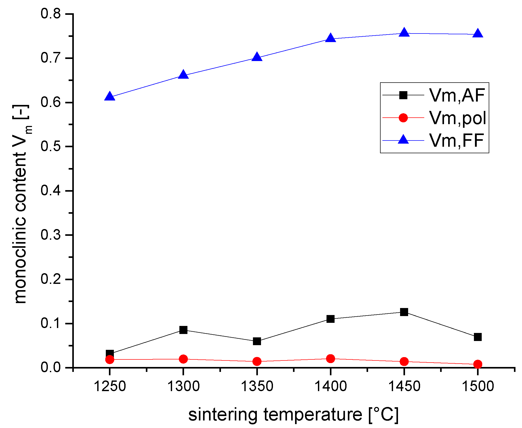
Figure 7 shows the monoclinic contents in as-fired surface, polished surface and fracture surface of bars after 4pt bending test. The as-fired surfaces exhibit a considerable monoclinic content which increases from 3 vol.% at 1250 °C to 13 vol.% at 1450 °C sintering temperature. The polished surfaces exhibit significantly lower monoclinic contents in the range of 1-2 vol.%. The monoclinic content in the fracture surfaces increase with sintering temperature from 61 vol.% at 1250 °C to 75 vol.% at 1400 °C, then no further increase is observed. At high sintering temperature the measured monoclinic contents are close to the theoretically possible ones of ~ 85 vol.% quoted by Mamivand [31]. The transformability Vf which is required to calculate the transformation toughness is calculated as Vf = Vm,FF - Vm,pol.
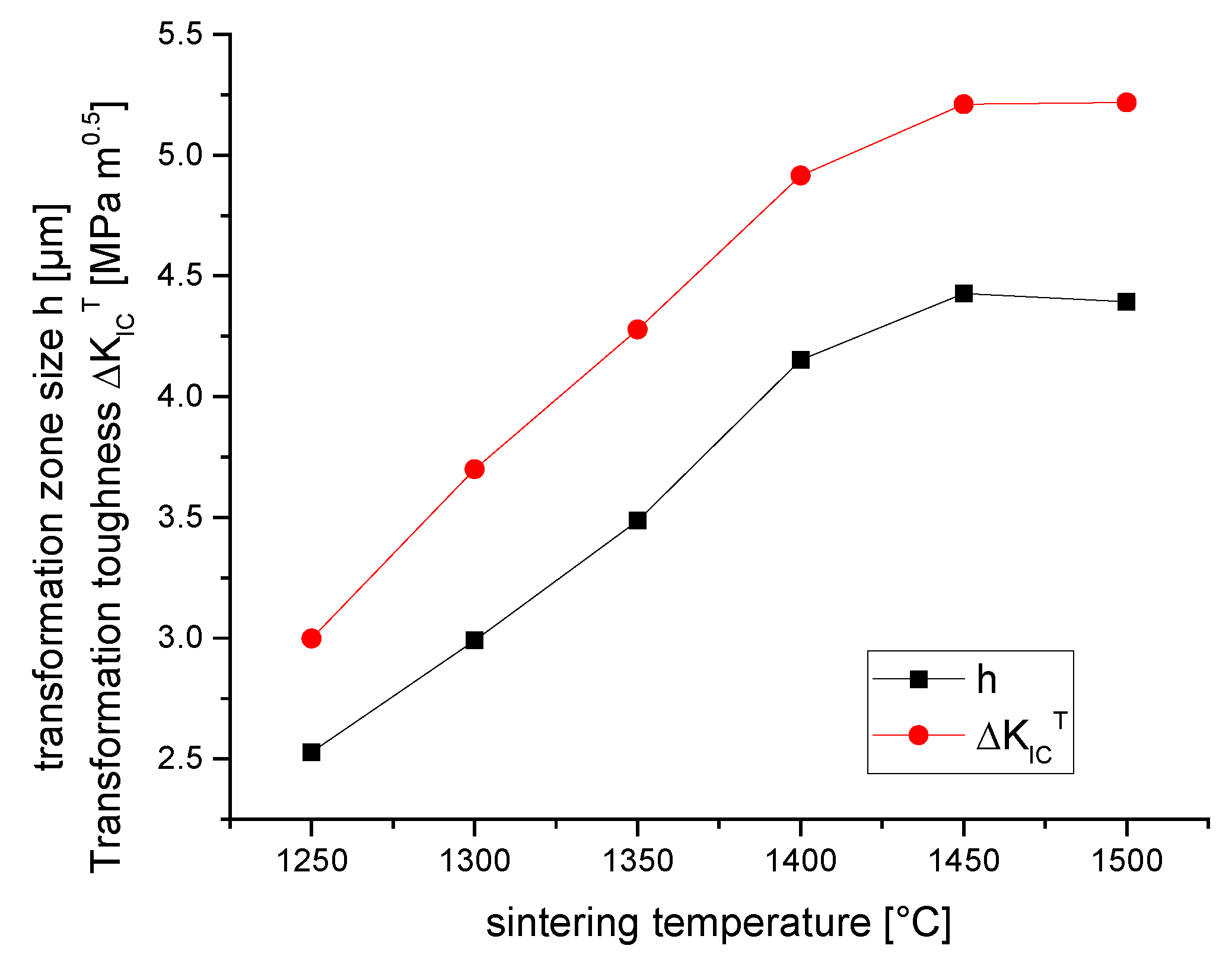
Figure 8 shows the transformation zone sizes h according to Kosmac [25] and the corresponding transformation toughness values ΔKICT according to McMeeking [26] which were obtained by evaluation of XRD data of polished and fractured surfaces.
Transformation zone sizes reach a maximum of 4.5 µm at sintering temperatures between 1400 °C-1500 °C. The calculated transformation toughness increases from 3 MPa√m at 1250 °C to 5 MPa√m at 1400 °C at higher temperature the transformation toughness stays at this level.
Assuming toughening effects are additive, the total fracture toughness can be calculated as KIC = K0 + KICT in absence of other toughening mechanisms than TT. Literature data for the crack tip toughness or intrinsic toughness K0 (in absence of reinforcement effects) are between: K0 = 3 MPa√m [23] and K0 = 4 MPa√m [30,32]. Therefore, on the basis of XRD data and theoretical considerations the maximum toughness of the material may not exceed 8-9 MPa√m. This implies that both DCM and ISB values (Figure 3) are exaggerated and that the measured SIGB toughness data (Figure 4) are within the calculated range or slightly below.

4. Discussion

The 2Y-TZP material investigated shows an attractive combination of strength and fracture toughness. An in depth study of transformation behavior and calculation of the maximum transformation toughness increment confirms that direct crack length measurement and ISB tests both lead to drastic overestimations of the fracture toughness values. The reason for this can be found in crack trapping effects as described by Cook [21]. The cracks induced by HV10 indents are trapped in the transformation zone resulting not only in extremely short crack lengths but also very frequently in irregular crack patterns which are difficult to interpret. Similar conclusions are obtained comparing the results of Matsui and Imarouane who studied a quite similar understabilized 1.5Y-TZP material [16,17]. In ISB tests cracks are extended due to tensile stress during loading the sample to failure. However, if the cracks are trapped within the transformation zone the sample will fail at short crack extension immediately when the crack exits the shielded zone around the indent rather than grow evenly, this sudden bursting of ISB bars resulted in residual strength levels of up to 1000 MPa. The chosen procedure to place indentations at elevated temperature (250 °C – 300 °C) at least reduces the transformability and allows the cracks to grow during the SIGB test. However, this solution cannot be applied in all samples, the sample sintered at 1500 °C turned out to be vulnerable to heating and transformed at this temperature. XRD measurements and calculation of fracture toughness using the model of McMeeking and Evans [26] allows to estimate the possible maximum toughness in this 2Y-TZP (8-9 MPa√m). The SIGB tests carried out with samples indented at elevated temperature lead to toughness values within or below this range. It has to be considered that samples are small and toughness values were not extrapolated to larger crack lengths, this may account for slight underestimations. Moreover a constant transformation efficiency of X = 0.27 (predominantly but not exclusively dilational) was applied for calculation. It could be that at high sintering temperatures and large grain sizes the transformation efficiency may decline as in case of Ce-TZP materials [2].
Another point worth discussing in the context of Ref. [18] is the elevated monoclinic content of the as fired surface compared to polished surfaces. Thermal etching also led to uneven surfaces especially for samples sintered at higher temperatures. In the sintering cycles for the study the samples were cooled down with 12 K/min (or in case of lower temperature as fast as the thermal inertia of the furnace allowed it). These observations are in line with results of Imarouane on ageing of 1.5Y-TZP [18]. Maybe even faster cooling would be beneficial to prevent phase transformation. This increases the requirements to the furnace and kiln furniture and indicates possible difficulties in net-shape manufacturing of larger components.

5. Conclusions

The alumina doped 2Y-TZP tested in this study provides a combination of high toughness and high strength which makes the material attractive for structural applications requiring high damage tolerance for catastrophic events. Transformation toughness increments of up to 5 MPa√m represent the maximum of the theoretically possible value for Y-TZP materials. However, as the R-curve dependent toughness is so high the materials are probably prone to suffer from sub-critical crack growth i.e. they are not well suited to bear constant or alternating loads. Indentation based measurements may lead to overestimation of fracture toughness due to crack trapping and mistakes in the design of components. The best sintering condition is probably 1350 °C/2h as both strength and toughness reach their optimum, grain growth is still moderate and material is fully dense. Overfiring shifts the material into the transformation dominated range strength and toughness decrease and low temperature degradation may become an issue.

Author Contributions

Conceptualization, F.K. ; investigation F.K. and B.O.; writing—original draft preparation, F.K.; writing—review and editing, F.K and B.O.; visualization, B.O..;. All authors have read and agreed to the published version of the manuscript.

Funding

This research received no external funding.

Institutional Review Board Statement

Not applicable.

Data Availability Statement

The raw data supporting the conclusions of this article will be made available by the authors on request.

Conflicts of Interest

The authors declare no conflicts of interest.

References

  1. Hannink, R.H.J.; Kelly, P.M.; Muddle, B.C. Transformation Toughening in Zirconia-Containing Ceramics. Journal of the American Ceramic Society 2000, 83, 461–487. [Google Scholar] [CrossRef]
  2. Kelly, P.M.; Rose, L.R.F. The martensitic transformation in ceramics — its role in transformation toughening. Progress in Materials Science 2002, 47, 463–557. [Google Scholar] [CrossRef]
  3. Rose, L.R.F. The mechanics of transformation toughening. Proc. R. Soc. Lond. A 1987, 412, 169–197. [Google Scholar] [CrossRef]
  4. Li, P.; Chen, I.-W.; Penner-Hahn, J.E. Effect of Dopants on Zirconia Stabilization - An X-ray Absorption Study: I, Trivalent Dopants. Journal of the American Ceramic Society 1994, 77, 118–128. [Google Scholar] [CrossRef]
  5. Li, P.; Chen, I.-W.; Penner-Hahn, J.E. Effect of Dopants on Zirconia Stabilization - An X-ray Absorption Study: II, Tetravalent Dopants. Journal of the American Ceramic Society 1994, 77, 1281–1288. [Google Scholar] [CrossRef]
  6. Chen, M.; Hallstedt, B.; Gauckler, L.J. Thermodynamic modeling of the ZrO2–YO1.5 system. Solid State Ionics 2004, 170, 255–274. [Google Scholar] [CrossRef]
  7. Kelly, J.R.; Denry, I. Stabilized zirconia as a structural ceramic: An overview. Dent. Mater. 2008, 24, 289–298. [Google Scholar] [CrossRef]
  8. Matsui, K.; Yoshida, H.; Ikuhara, Y. Phase-transformation and grain-growth kinetics in yttria-stabilized tetragonal zirconia polycrystal doped with a small amount of alumina. Journal of the European Ceramic Society 2010, 30, 1679–1690. [Google Scholar] [CrossRef]
  9. Chevalier, J.; Gremillard, L.; Virkar, A.V.; Clarke, D.R. The Tetragonal-Monoclinic Transformation in Zirconia: Lessons Learned and Future Trends. Journal of the American Ceramic Society 2009, 92, 1901–1920. [Google Scholar] [CrossRef]
  10. Ruiz, L.; Readey, M.J. Effect of Heat Treatment on Grain Size, Phase Assemblage, and Mechanical Properties of 3 mol% Y-TZP. J Am Ceram Soc 1996, 79, 2331–2340. [Google Scholar] [CrossRef]
  11. Binner, J.; Vaidhyanathan, B.; Paul, A.; Annaporani, K.; Raghupathy, B. Compositional Effects in Nanostructured Yttria Partially Stabilized Zirconia. International Journal of Applied Ceramic Technology 2011, 8, 766–782. [Google Scholar] [CrossRef]
  12. Chevalier, J.; Cales, B.; Drouin, M. Low-Temperature Aging of Y-TZP Ceramics. Journal of the American Ceramic Society 1999, 82, 2150–2154. [Google Scholar] [CrossRef]
  13. Lange, F.F. Transformation toughening: Part 3 Experimental observations in the ZrO2- Y203 system. Journal of Materials Science 1982, 17, 240–246. [Google Scholar] [CrossRef]
  14. Tsukuma, K. Thermal and Mechanical Properties of Y2O3-Stabilized Tetragonal Zirconia Polycrystals, Science and Technology of Zirconia II. Advances in Ceramics 1984, 12, 382–390. [Google Scholar]
  15. Kern, F.; Reveron, H.; Chevalier, J.; Gadow, R. Mechanical behaviour of extremely tough TZP bioceramics. J. Mech. Behav. Biomed. Mater. 2019, 90, 395–403. [Google Scholar] [CrossRef] [PubMed]
  16. Matsui, K.; Hosoi, K.; Feng, B.; Yoshida, H.; Ikuhara, Y. Ultrahigh toughness zirconia ceramics. Proc. Natl. Acad. Sci. U. S. A. 2023, 120, e2304498120. [Google Scholar] [CrossRef] [PubMed]
  17. Imariouane, M.; Saâdaoui, M.; Denis, G.; Reveron, H.; Chevalier, J. Low-yttria doped zirconia: Bridging the gap between strong and tough ceramics. Journal of the European Ceramic Society 2023, 43, 4906–4915. [Google Scholar] [CrossRef]
  18. Imariouane, M.; Saâdaoui, M.; Cardinal, S.; Reveron, H.; Chevalier, J. Aging behavior of a 1.5 mol% yttria doped zirconia exhibiting optimized toughness and strength. Journal of the European Ceramic Society 2024, 44, 1053–1060. [Google Scholar] [CrossRef]
  19. Niihara, K. A fracture mechanics analysis of indentation-induced Palmqvist crack in ceramics. Journal of Materials Science Letters 1983, 2, 221–223. [Google Scholar] [CrossRef]
  20. Chantikul, P.; Anstis, G.R.; Lawn, B.R.; Marshall, D.B. A Critical Evaluation of Indentation Techniques for Measuring Fracture Toughness: II, Strength Method. Journal of the American Ceramic Society 1981, 64, 539–543. [Google Scholar] [CrossRef]
  21. Cook, R.F.; Braun, L.M.; Cannon, W.R. Trapped cracks at indentations: Part I: Experiments on yttria-tetragonal zirconia polycrystals. Journal of Materials Science 1994, 29, 2133–2142. [Google Scholar] [CrossRef]
  22. Dransmann, G.W.; Steinbrech, R.W.; Pajares, A.; Guiberteau, F.; Dominguez-Rodriguez, A.; Heuer, A.H. Indentation Studies on Y2O3-Stabilized ZrO2: II, Toughness Determination from Stable Growth of Indentation-Induced Cracks. J American Ceramic Society 1994, 77, 1194–1201. [Google Scholar] [CrossRef]
  23. Benzaid, R.; Chevalier, J.; Saadaoui, M.; Fantozzi, G.; Nawa, M.; Diaz, L.A.; Torrecillas, R. Fracture toughness, strength and slow crack growth in a ceria stabilized zirconia-alumina nanocomposite for medical applications. Biomaterials 2008, 29, 3636–3641. [Google Scholar] [CrossRef] [PubMed]
  24. Toraya, H.; Yoshimura, M.; Somiya, S. Calibration Curve for Quantitative Analysis of the Monoclinic-Tetragonal ZrO2 System by X-Ray Diffraction. Journal of the American Ceramic Society 1984, 67, C119–C121. [Google Scholar] [CrossRef]
  25. Kosmać, T.; Wagner, R.; Claussen, N. X-Ray Determination of Transformation Depths in Ceramics Containing Tetragonal ZrO2. Journal of the American Ceramic Society 1981, 64, C–72. [Google Scholar] [CrossRef]
  26. McMeeking, R.M.; Evans, A.G. Mechanics of Transformation-Toughening in Brittle Materials. J Am Ceram Soc 1982, 65, 242–246. [Google Scholar] [CrossRef]
  27. Mendelson, M.I. Average Grain Size in Polycrystalline Ceramics. Journal of the American Ceramic Society 1969, 52, 443–446. [Google Scholar] [CrossRef]
  28. Liens, A.; Swain, M.; Reveron, H.; Cavoret, J.; Sainsot, P.; Courtois, N.; Fabrègue, D.; Chevalier, J. Development of transformation bands in ceria-stabilized-zirconia based composites during bending at room temperature. Journal of the European Ceramic Society 2021, 41, 691–705. [Google Scholar] [CrossRef]
  29. Billovits, T.; Demel-Eckhart, S. Exploring the boundaries of strength and toughness: AuerTec® 2Y- 40A, extended abstract ECERS XVIII, Lyon, France. Available online: https://www.ecers2023.org/data/onglet34/module0/modalPreview.php?langue=fr&paramProjet=89 (accessed on 15 May 2024).
  30. Swain, M.V.; Rose, L.R.F. Strength Limitations of Transformation-Toughened Zirconia Alloys. Journal of the American Ceramic Society 1986, 69, 511–518. [Google Scholar] [CrossRef]
  31. Mamivand, M.; Asle Zaeem, M.; El Kadiri, H. Phase field modeling of stress-induced tetragonal-to-monoclinic transformation in zirconia and its effect on transformation toughening. Acta Materialia 2014, 64, 208–219. [Google Scholar] [CrossRef]
  32. Evans, A.G. Perspective on the Development of High-Toughness Ceramics. J Am Ceram Soc 1990, 73, 187–206. [Google Scholar] [CrossRef]
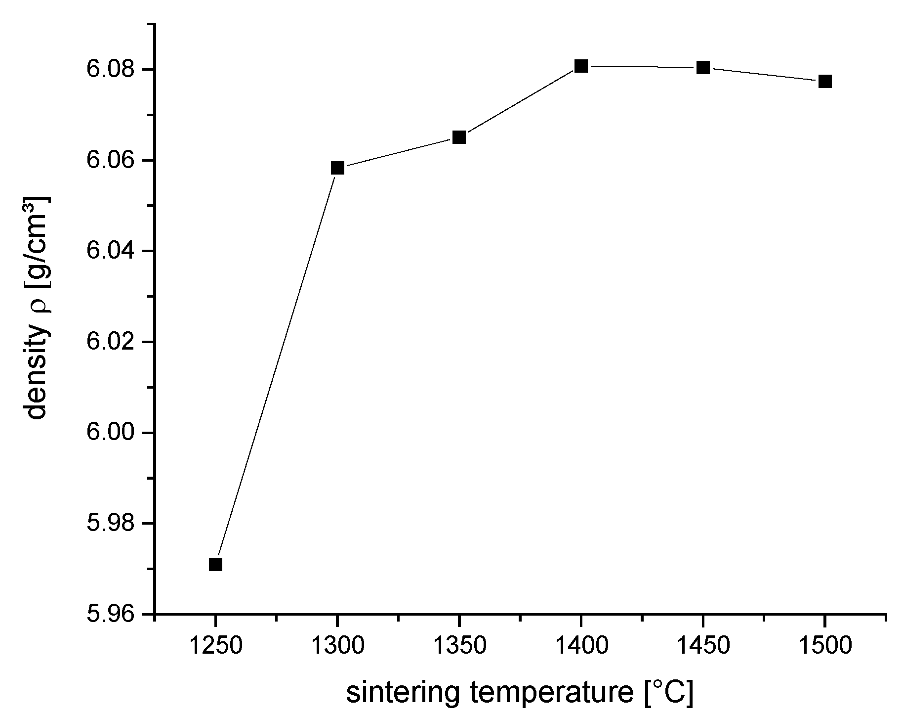
Figure 1. Density ρ of TZP samples sintered at different temperatures.
Preprints 107266 g001
Figure 2. Vickers hardness HV10 and bending strength σ4pt of TZPs sintered at different temperatures.
Preprints 107266 g002
Figure 3. Fracture toughness values KDCM and KISB of TZPs sintered at different temperatures.
Preprints 107266 g003
Figure 4. Fracture toughness values KSIGB of TZPs sintered at different temperatures, samples notched at elevated temperature.
Preprints 107266 g004
Figure 5. Microstructure of 2Y-TZP (polished and thermally etched surfaces). a. 1250 °C/2 h b. 1300 °C/2 h c. 1350 °C/2 h d. 1400 °C/2 h e. 1450 °C/2 h f. 1500 °C/2 h.
Preprints 107266 g005
Figure 6. Grain size of 2Y-TZP determined by line intercept method (correction factor 1.56).
Preprints 107266 g006
Figure 7. Monoclinic contents of TZP materials sintered at different temperatures measured by XRD Vm,AF in as fired surface, Vm,pol in polished surface and Vm,FF in fracture surface.
Preprints 107266 g007
Figure 8. Transformation zone size h and transformation toughness ΔKICT of of TZP materials sintered at different temperatures.
Preprints 107266 g008
Disclaimer/Publisher’s Note: The statements, opinions and data contained in all publications are solely those of the individual author(s) and contributor(s) and not of MDPI and/or the editor(s). MDPI and/or the editor(s) disclaim responsibility for any injury to people or property resulting from any ideas, methods, instructions or products referred to in the content.
Copyright: This open access article is published under a Creative Commons CC BY 4.0 license, which permit the free download, distribution, and reuse, provided that the author and preprint are cited in any reuse.
Prerpints.org logo

Preprints.org is a free preprint server supported by MDPI in Basel, Switzerland.

Subscribe

© 2024 MDPI (Basel, Switzerland) unless otherwise stated