1. Introduction
In recent years, there has been significant interest in developing bio-inspired swimming vehicles that emulate the propulsive methods of biological systems. Biological swimmers utilize their bodies and propulsors to achieve remarkable maneuverability and agility, inspiring engineers to model these systems for improving the performance of underwater vehicles [
1,
2,
3]. Existing bio-inspired swimming robots include fish robots that make use of multiple fins to produce propulsive forces and maneuvers [
4,
5,
6], sea turtles with soft actuator driven flippers [
7], and sea snakes capable of contorting to navigate tight areas [
8]. The California sea lion is an excellent model for bio-inspired swimming systems due to its exceptional maneuverability and agility, especially in high-energy flow environments [
9]. Its unique propulsion method, which relies heavily on the coordinated movement of its foreflippers, allows it to achieve impressive swimming performance [
10]. However, replicating this coordination in a robotic system poses significant challenges.
Reinforcement learning (RL) offers a promising approach to address the challenge of coordinating the propulsive elements of a robotic system inspired by the California sea lion. RL has proven effective in terrestrial applications by transferring quadruped animal walking gaits onto robotic quadrupeds using RL [
11] and teaching humanoid bipedal robots how to walk effectively [
12]. Additionally, in an underwater context, RL has been successfully deployed to train a beaver like swimmer [
13], underwater armed manipulators [
14], and a simple two degree of freedom fin-based swimming systems [
15]. High-fidelity models are essential for RL due to the substantial number of trials required for effective learning [
16,
17]. Training directly on a numerical model reduces the risk of damage, shortens training time, and enhances state space exploration, potentially improving gait outcomes. However, developing a high-fidelity underwater bio-robotic model is computationally costly due to fluidic complexities and lengthy simulation times. Any simulation of underwater swimming robots used for RL must produce accurate results while operating at relevant time scales. To use RL to coordinate the sea lion propulsors effectively, the characteristic flipper kinematics used by the animal during swimming must be understood, and a high-fidelity model of the robotic system must be developed.
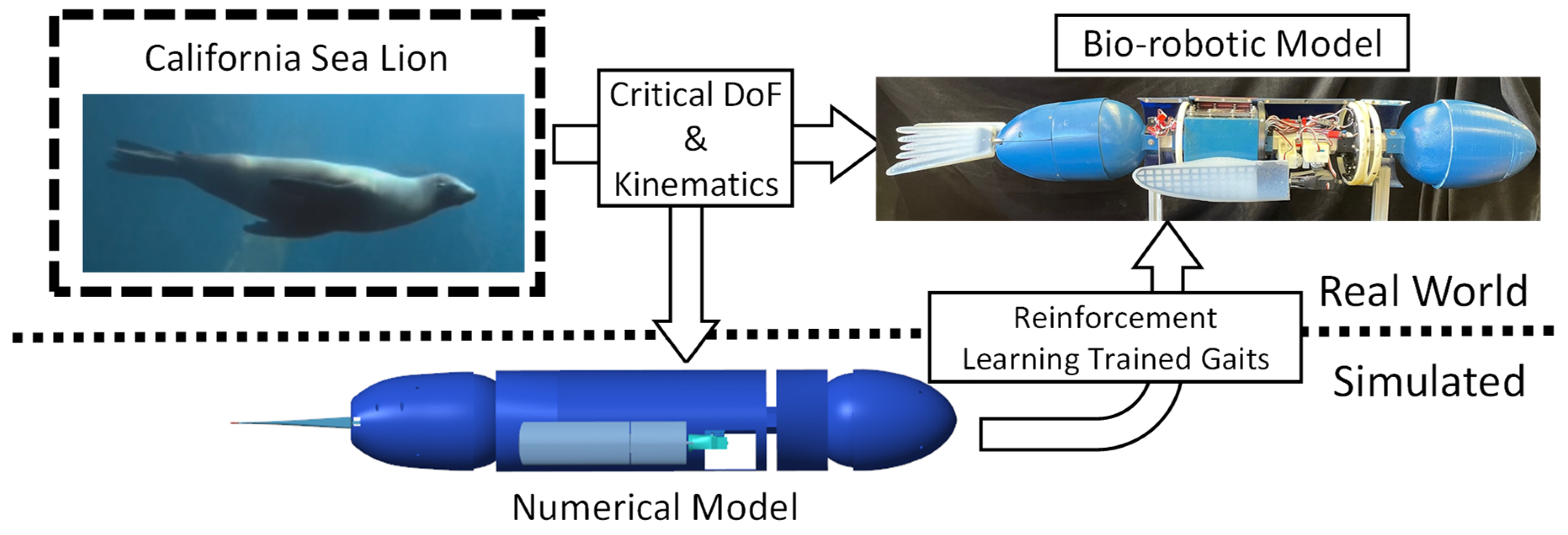
The objective of this work was to evaluate the effectiveness of applying reinforcement learning to modify a characteristic California sea lion propulsive stroke to produce a new straight swimming gait to be deployed on a swimming bio-robotic sea lion [
Figure 1]. The process that was followed included: (1) an analysis of the sea lion during natural swimming, (2) the development and validation of bio-robotic and numerical models of a California sea lion, (3) the application of reinforcement learning to train the kinematics of the foreflippers in simulation to produce desired swimming performance, (4) a comparison of performance of the observed characteristic biological sea lion swimming gait and the learned gait in simulation and on the bio-robotic platform [
Figure 1].
2. Materials and Methods
2.1. The Sea Lion Fore-Flipper Stroke Model
Videos of the California sea lion (Zalophus californianus) was analyzed to identify the characteristic gaits and body motions used during natural swimming [
9,
10]. Unmarked and non-research sea lions were observed and filmed at the Smithsonian Zoological Park through a sizable underwater glass viewing window large enough to capture, at minimum, 3-4 sea lion body lengths. Using a stationary camera (GC-PX100BU, JVC, Japan), videos were recorded as the sea lions passively swam [
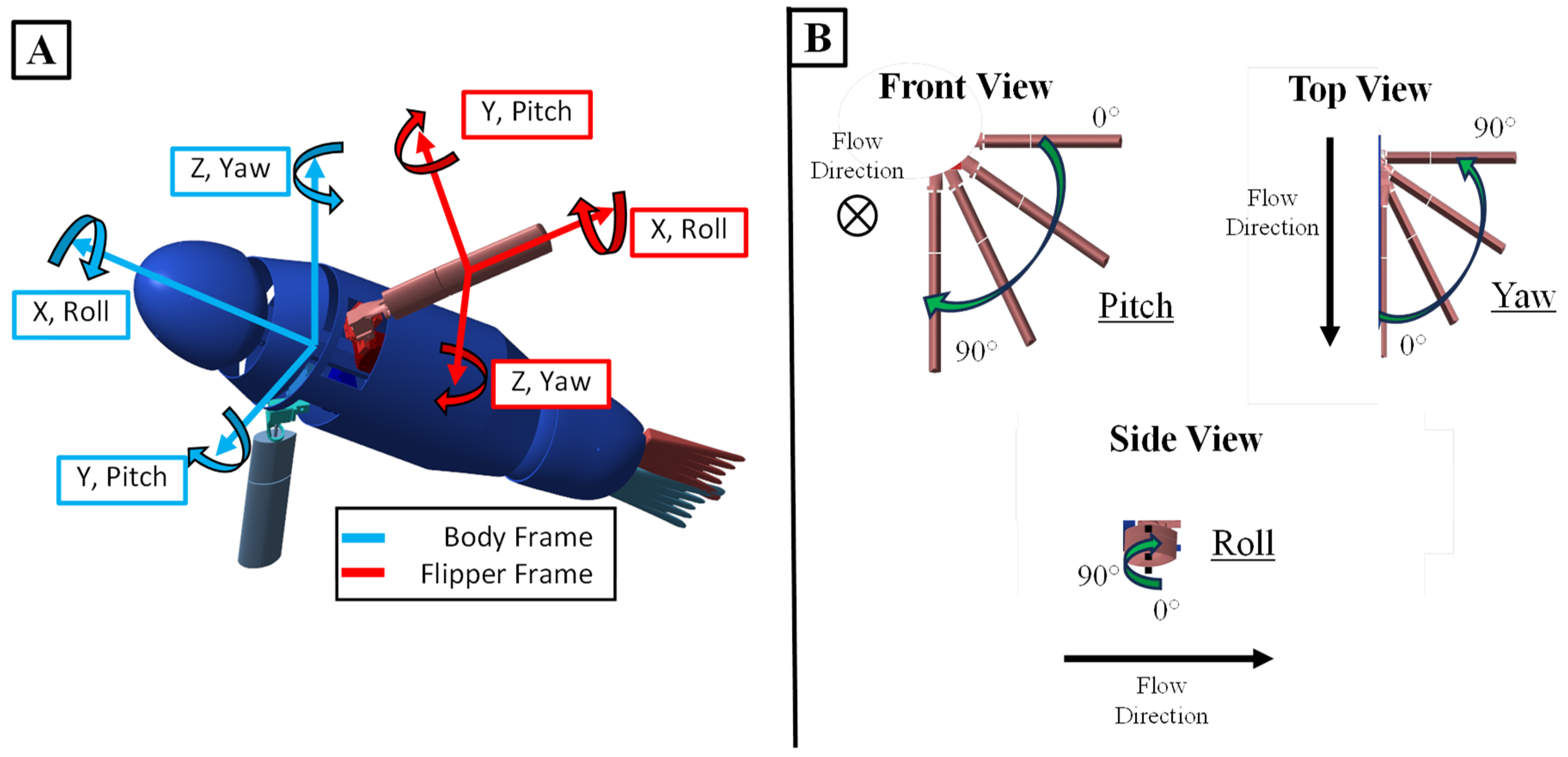
Figure 2]. Crucial factors were identified, including a manipulatable head/cervical section, flexible pelvic section, pelvic flippers for control, and foreflippers as primary propulsive devices. The kinematics of the characteristic sealion stroke have been well described in previous works [
10]. Additional videos were recorded from several different angles of multiple sea lions free swimming in a zoo setting [
Figure 2]. The video footage was analyzed to determine the foreflipper motion at the base of the foreflipper [
Figure 2]. The resulting kinematics were in alignment with previous works.
These tracked kinematics were used as basis for the development of a generalized model for the kinematics of the sea lion foreflippers.
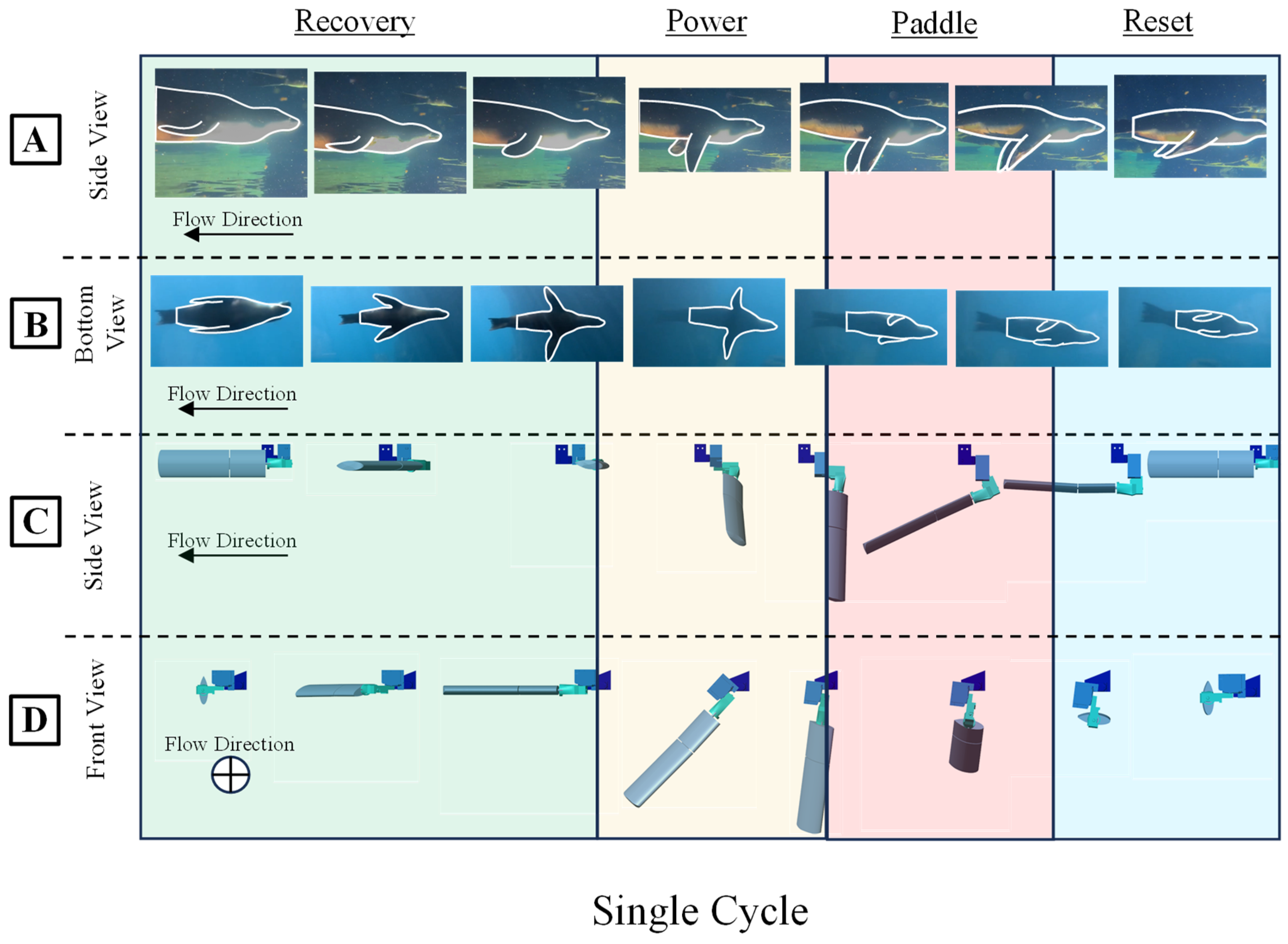
The sealion propulsive stroke cycle is divided into three distinct phases: recovery, power, and paddle. During the recovery phase, the foreflipper aligns with the flow direction through yaw and roll motions, extending laterally for low drag, setting up for propulsion direction [
Figure 2 and
Figure 3]. The subsequent power phase involves pitch rotation, pulling the flipper towards and beneath the body midline, with decreased roll orienting the leading edge towards the motion direction [
Figure 2 and
Figure 3]. This is followed by the paddle phase, where the flippers yaw and roll inward, aligning the flipper face with the motion direction and concluding with the flippers in a streamlined position beside the body direction [
Figure 2 and
Figure 3]
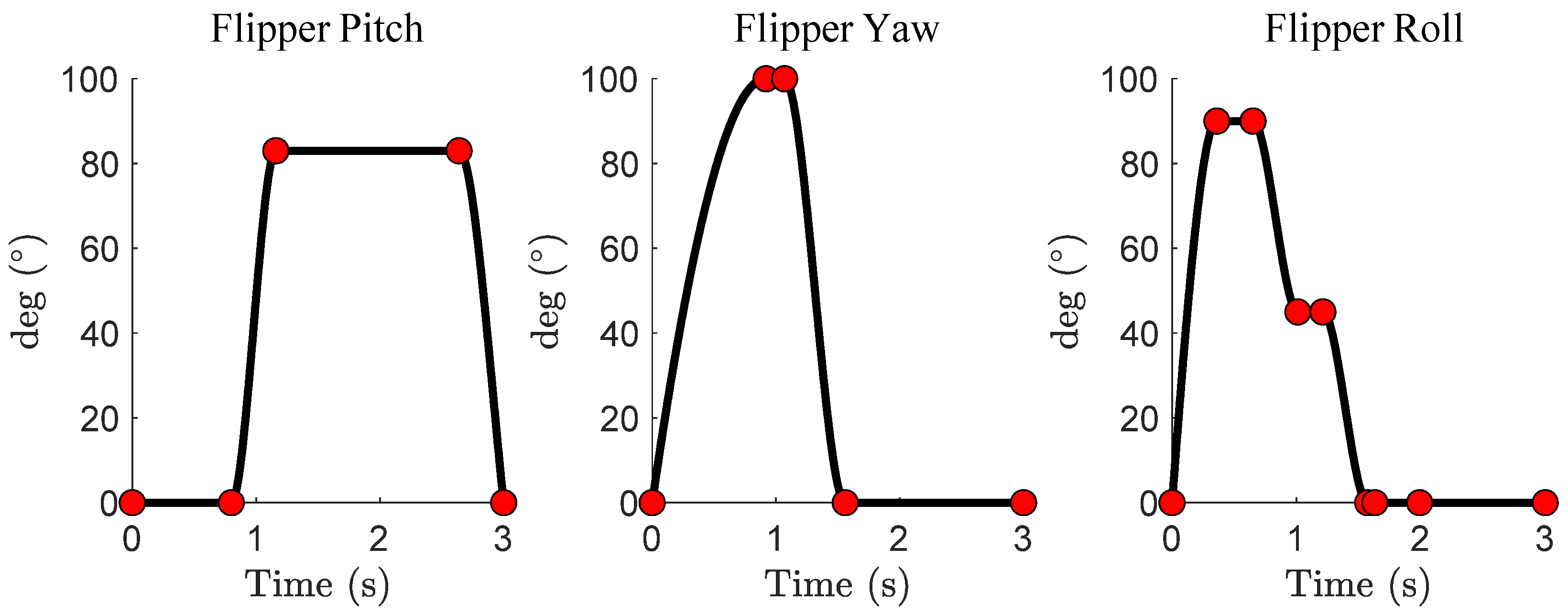
A generalized and parameterized model of a sea lion’s foreflipper stroke was developed. A Piecewise Cubic Hermite Interpolating Polynomial (PCHIP) spline was fit by hand to generalized kinematics obtained from a combination of the sea lion videos and previous work on the sea lion stroke [
10] [
Figure 4]. PCHIP splines offer bounded magnitudes between control points and support double differentiation, ensuring a smooth trajectory [
Figure 4]. By adjusting the control points of the spline, the flipper trajectory can produce a range of motions, from accurately mimicking the sea lion’s characteristic propulsive stroke to entirely random movements resulting in no forward propulsion. More specific alterations for the purpose of reinforcement learning will be discussed in Section 2.4.
2.2. The Bio-Robotic Sealion
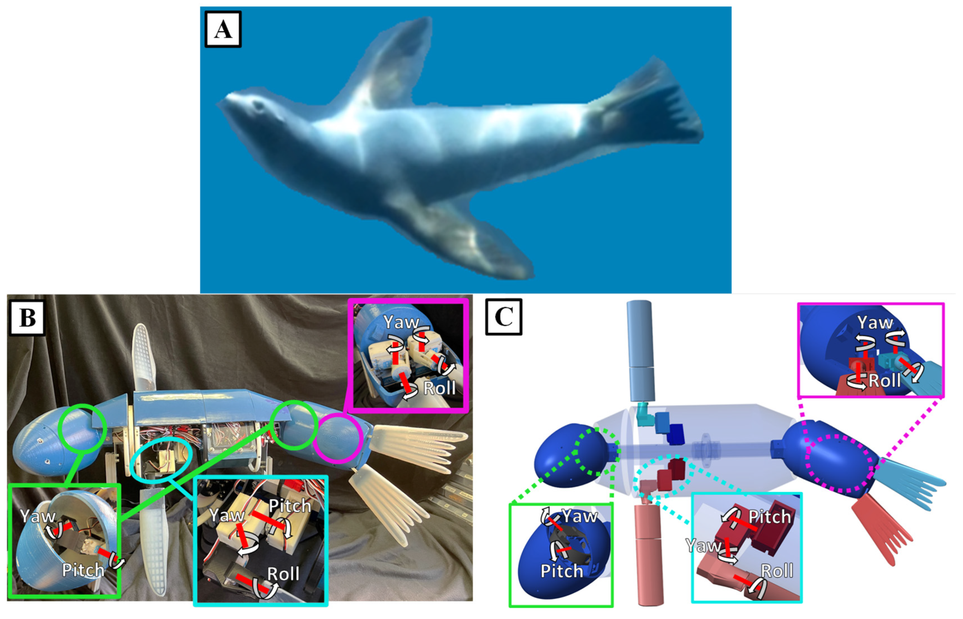
A bio robotic system known as the Stroke Experimentation and Maneuver Optimizing Underwater Robot (SEAMOUR) was developed to model the swimming and maneuvering of the California sea lion. The important biological features for swimming and maneuvering have been identified by experts+. The bio-robotic system models five important segments of the sea lion for swimming and maneuvering: the head/neck section, the main body, the foreflippers, the pelvic section, and the pelvic flippers. The position and scale of these sections were based off the sea lion animal. Also like the animal, SEAMOUR is laterally symmetric down the centerline of the body but is about half the total length at 1m. SEAMOUR has access to 14 degrees of freedom (DoF) to control its flippers and actuate its head and pelvic section. The head and pelvic sections both utilize a two-axis gimbal system for yaw and pitch motion that enables them to transform 60° in all directions. The pelvic section houses four motors, two for each flipper, that give the pelvic flippers their ability to roll and yaw. Each foreflipper is driven by three servo motors giving the flipper the ability to roll, pitch, and yaw [
Figure 5B]. These DoF enable each foreflipper to execute a broad range of trajectories.
The foreflipper is made with an ABS 3D printed (F120, Stratasys, USA) grid support structure that is cast into an uncambered airfoil shape using a 2-part silicone (Smooth-on, USA) with a shore hardness of 00-30. While the foreflipper shape was simplified, careful consideration was taken to preserve the bending location, and the amount of tip displacement, during swimming. Using Solidworks CAD software (Solidworks, USA), finite element analysis (FEA) was done to simulate the bending of the foreflipper when subjected to an estimated peak fluidic loading during a propulsive stroke.
The body of the robotic platform is a streamlined ellipsoid shape with the power and control components housed in a waterproof box located in the interior section. SEAMOUR is operated with a modified Raspberry Pi 4, equipped with an extension antenna designed to breach the water’s surface, enabling untethered remote control. Adding mass and extruded polystyrene foam to various locations throughout the body is utilized not only to trim the system’s pitch and roll but also to modify the desired center of mass and center of buoyancy as well as to achieve neutral buoyancy.
2.3. The Numerical Model of the Bio-Robotic Sealion
A numerical model of SEAMOUR was developed to test swimming gaits, body motions, and served as a reinforcement learning training environment in an underwater domain. Created using Simscape (MATLAB and Simscape Toolbox Release 2022a, The MathWorks, Inc., Natick, Massachusetts, USA), this model is a true-to-scale representation of SEAMOUR, providing a detailed simulation of its mechanical components. It allows for realistic visualization and simulation of the robot’s 6 DoF body movements [
Figure 5C]. The model also accounted for inertial forces and the hydrostatic and hydrodynamic forces experienced by the bio-robotic system underwater. The passive bending in the foreflippers was modeled through a spring-mass damper connecting two rigid flat plates.
To model this complex bio-robotic system, several assumptions were made: the model was neutrally buoyant and fully submerged in a fluid that is incompressible and has no skin friction [
18]. The main body, including the head and pelvic section, was considered a prolate spheroid [
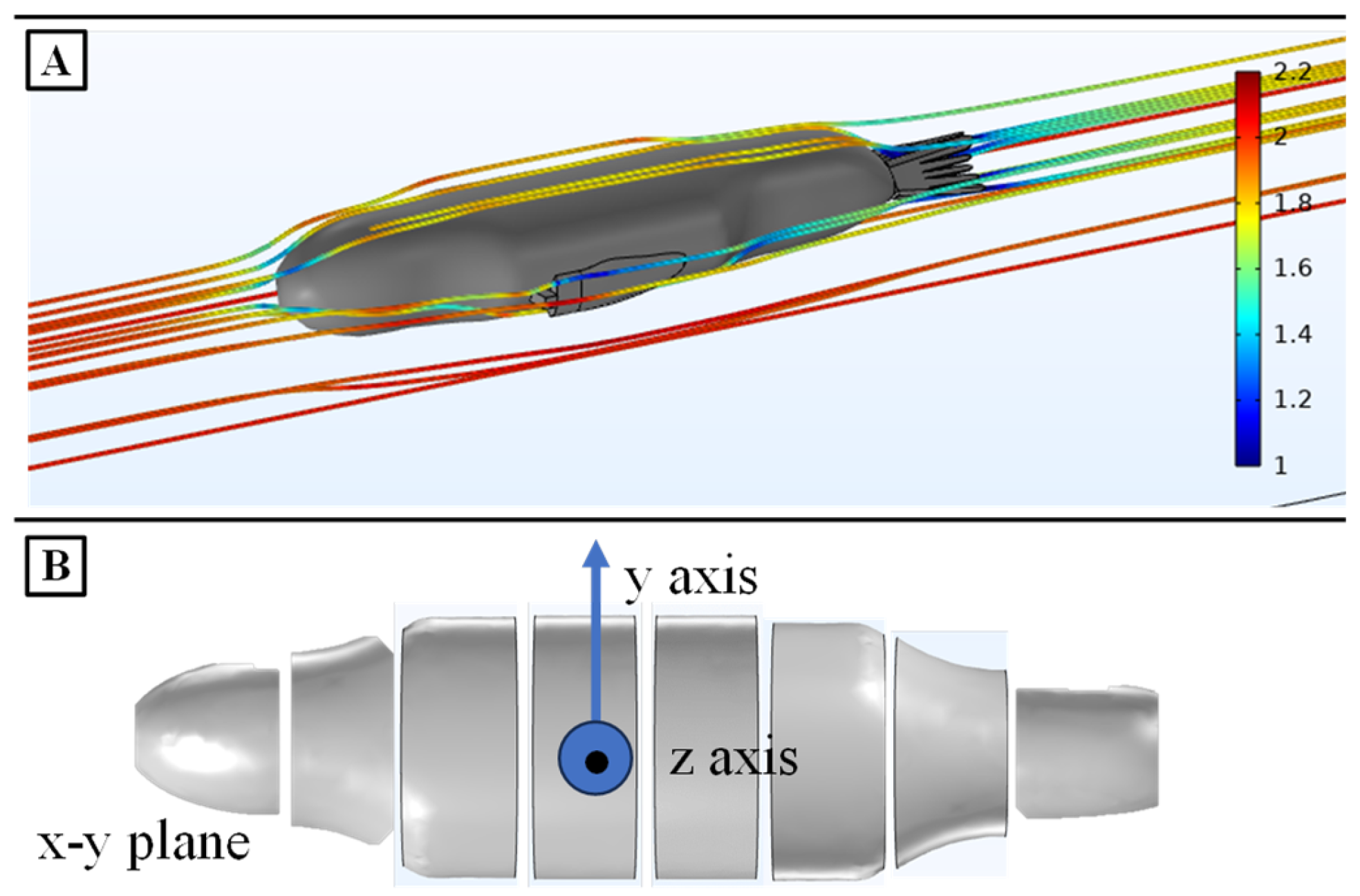
Figure 6B]. The foreflippers and pelvic flippers were considered rectangular flat plates. Each part of SEAMOUR was modeled in a 3D CAD software and added to the model. The head, body, pelvic section, pelvic flippers, and foreflippers of SEAMOUR were experimentally weighed and those weights were added to the simscape model. SEAMOUR was designed as an open system that allows water ingress. The water volume within the robot was estimated by subtracting the combined volume of its internal components from the total robot volume, incorporating it as additional mass. The mass and center of mass for each part were calculated based on the dry weight of each part and the weight of the flooded volume of water. Joint torques at each connection point are automatically calculated in the simscape environment.
To model fluid forces on the robot, both hydrostatic and hydrodynamic forces were considered. Hydrostatic forces factored in gravity and buoyancy, applying gravitational and buoyant forces to each core component. The center of buoyancy coincided with the center of gravity for the flippers, head, and pelvic section. For the main body, the center of gravity was positioned directly below the center of buoyancy with a slight offset to enhance stability along the roll and pitch axes and reflect the actual center of mass and center of buoyancy of SEAMOUR. The model assumed symmetry in all three axes.
To model the fluid forces, hydrodynamic forces such as drag and added mass forces were calculated and applied. For the dynamically moving head and pelvic section in this multi-body model, the primary body was divided into eight sections down the roll axis of the body [
Figure 6B]. Drag and added mass forces, proportional to each section’s surface area, were applied at the centers of each section [[
18], eq. 2.121]. To determine coefficients for drag forces, a simplified three-dimensional computational fluid dynamic simulation was developed using COMSOL Multiphysics (COMSOL, Inc., Boston, Massachusetts) [
Figure 6A]. A streamlined SEAMOUR model was imported directly into COMSOL. The x-direction drag coefficient was computed as the integral of total stress along the body in that direction. Similarly, all eight sections were used to calculate drag and lift coefficients in the y and z axes, along with their cross-sectional areas. These coefficients were then used to compute drag and lift forces in all axes using
where
is the drag coefficient, r is the density of fluid, v is the velocity of the body and A is the cross-sectional area. For the flippers, the drag (1) and added mass forces were integrated along the length of the flipper and applied directly to the center of mass of the flippers [[
18], eq. 2.121]. Hydrodynamic added mass coefficients for the main body (prolate spheroid) were computed using [[
18], eq. 2.142-2.149]. The added mass coefficients for the foreflippers and the pelvic flippers were computed using strip theory [
18] [[19], eq. 1]. A detailed description of the numerical model will be presented in a subsequent publication.
2.4. Reinforcement Learning
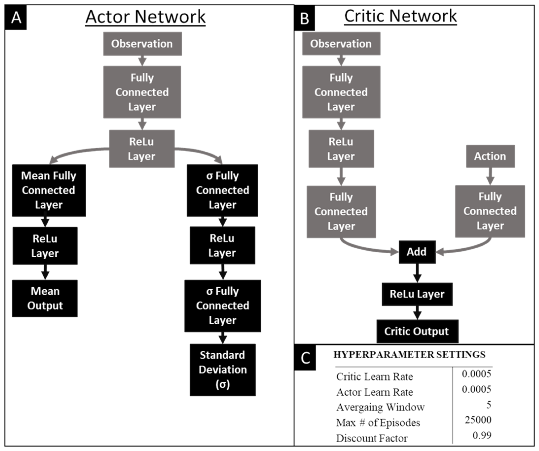
A reinforcement learning agent was applied to learn a novel straight swimming gait. The reinforcement learning agent selected was a Soft-Actor Critic (SAC). SAC agents provide many advantages for the purposes of learning effective robotic gaits [
Figure 7]. First, SAC can work with a continuous action space which is necessary to properly manipulate the motor trajectories. They are also robust to noisy and uncertain environments which occur frequently in real world environments and complicated multi-body simulations. Even though Soft Actor-Critic (SAC) agents may require more effort to implement compared to other popular alternatives like Proximal Policy Optimization (PPO), their effectiveness in handling continuous action spaces and ability to scale well with high-dimensional action spaces make it a desirable agent for this application. The structure of the critic and actor networks that train the agent are shown in
Figure 5. Pilot studies were conducted to improve hyperparameter tuning of the SAC [
Figure 7].
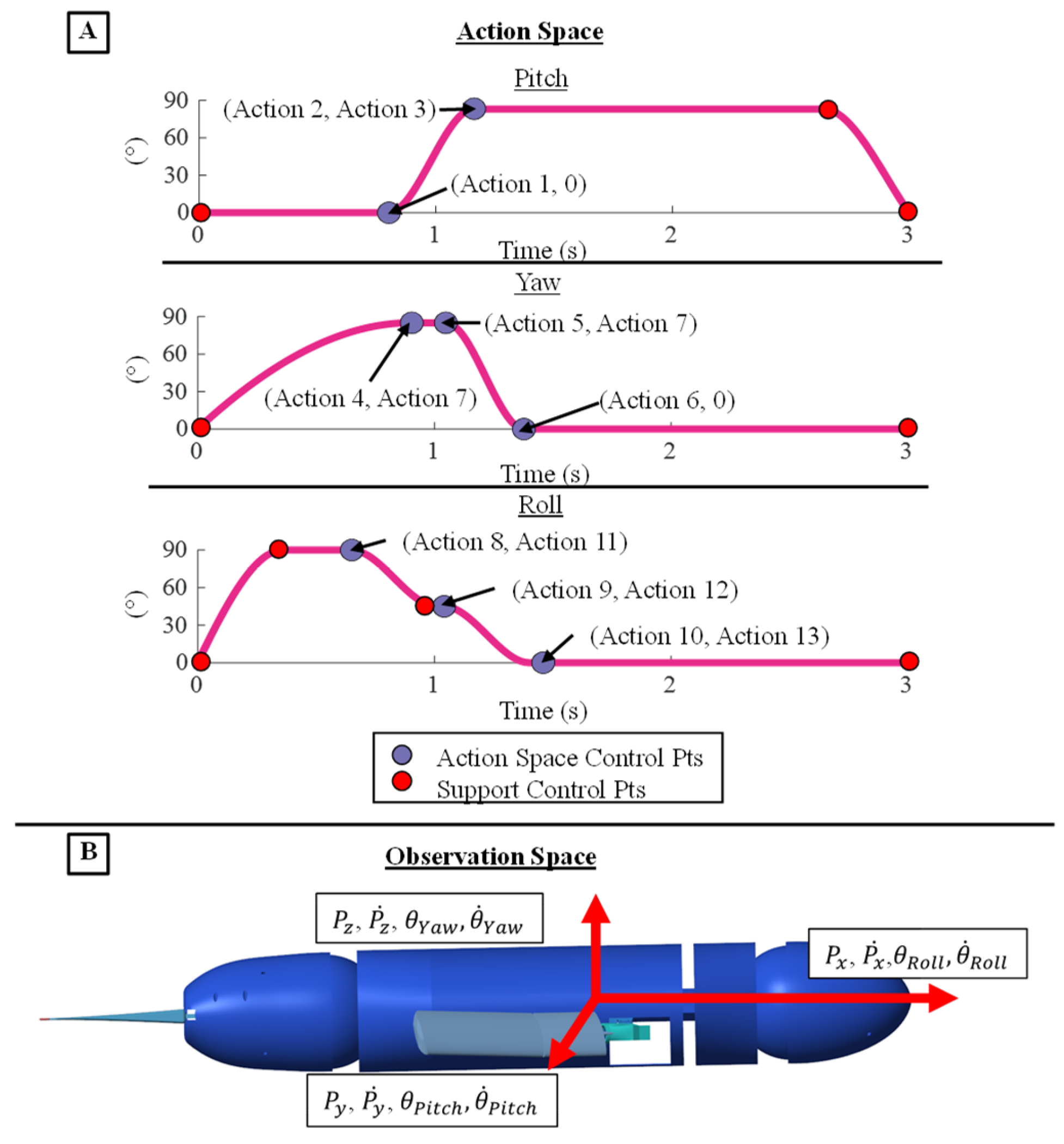
The coordinates of the control points of the generalized flipper stroke model served as the action space for the reinforcement learning agent. Specifically, the action space consisted of the timings and magnitudes of multiple points that control the pitch, yaw, and roll flipper kinematics totaling 13 individual actions [
Figure 8A]. The actions that change the magnitude and timings of the control points were bound to be within the operational range of the motors that actuate the flipper kinematics [
Figure 8A]. The control points of the model that are not directly altered in the action space serve several purposes including maintaining the cyclic shape of the stroke, bounding motor velocities to within the operational range, preparing the flipper to reset at the end of a stroke, or they are directly tied to the control points changed by the agent. The PCHIP spline fit to the control points ensured a smooth transition between points without overshooting the set motor ranges and maintained twice differentiability of the trajectory. The period of the characteristic stroke was doubled, and an additional control point was added to change the pause time between flipper strokes. The controlled flipper kinematics were symmetric between the left and right flipper. The agent lacked access to additional degrees of freedom in the bio-robotic system like the head, pelvis, and pelvic flippers to simplify the initial reinforcement learning task and increase the likelihood of achieving an effective straight swimming gait [
Figure 8A].
For each learning episode, the body translation and translational velocities and the body angle and angular velocities along each axis were taken as the observation space for the reinforcement learning agent [
Figure 8B]. There were 12 total observations recorded at the beginning and end of each reinforcement learning episode. The learning episode was nine seconds long and consisted of a single learning step that produced three repeated stroke cycles with pauses in between. Given this single-step framework, observations and actions were updated only once per episode, a feature that could adversely impact convergence [
Figure 8B]. To address this issue, multiple full training cycles were executed in simulation, with the agents yielding the highest rewards being selected and the top-performing learned agent was ultimately chosen [
Figure 8B].
The goal of the reinforcement learning was to encourage a straight swimming gait and discourage any out of plane motion. This task was facilitated by the following reward function:
Where x was the total forward distance traveled at the end of the episode, Vx, Vy and Vz were the mean velocities over the episode with Vx being squared to further incentive forward motion. Φ, θ, and ψ were the three angles that represent the heading of the bio-robotic system at the end of the episode and , , and were their respective mean angular velocities of the duration of the episode. Each of these terms were equally weighted.
2.5. Experimental Setup and Data Collection
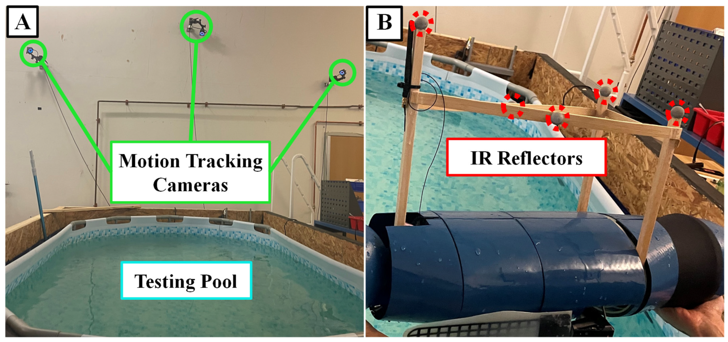
SEAMOUR was tested in an indoor laboratory setting using a 4.3m by 2.5m by 1m above-ground pool, while its movements were tracked by three motion capture cameras (OptiTrack, Prime X13, Oregon, USA) with a precision ranging from 0.5mm to 0.2mm in three-dimensional space [
Figure 9]. The tracking data was relayed to MATLAB via Motive software for recording and analysis. Each propulsive stroke variation underwent five separate trials and the resulting changes in position, velocities and headings were averaged.
To enable tracking of the bio-robotic platform, a lightweight balsa wood structure was attached to SEAMOUR, bearing infrared reflective tracking spheres. While minimizing the structure’s impact on system dynamics, additional mass was added to counterbalance the moment arm. To keep the structure above the water during testing, the robotic system was adjusted to maintain a neutral buoyancy state just below the water’s surface. This setup guaranteed continuous visibility of at least three tracking spheres, preserving tracking data accuracy, and preventing collisions with the pool’s bottom.
3. Results
3.1. Reinforcement Learning Convergence and Performance
This work demonstrated the effective application of reinforcement learning to develop a novel stroke for a bio-robotic sea lion platform using its numerical counterpart. The best novel gait from a selection of 100,000 trials was selected and learning times took ~ 3 hours. This newly developed stroke surpassed the performance in both velocity achieved and low deviation in heading of the biologically derived stroke in the numerical model. Upon integration into the bio-robotic system, both the learned and the characteristic stroke exhibited good rectilinear swimming performance metrics. Additionally, changes to roll and yaw were not reported as they remain unchanged in simulation due to the perfect symmetry of the flipper forces and hydrodynamic forces acting on the body.
The stroke developed from reinforcement learning had key differences in its trajectory when compared to the biologically derived characteristic stroke. Despite both strokes initiating from a streamlined position with the flippers positioned alongside the body, they diverged during the recovery phase. In the learned stroke, the flippers exhibited a feathering motion during recovery and directly transitioned into paddle stroke. This stroke eliminated the power stroke, a prominent feature seen in the biologically derived characteristic stroke; a better visual of both strokes can be seen in the attached video [
Figure 10].
3.2. Strokes Applied on Numerical Model
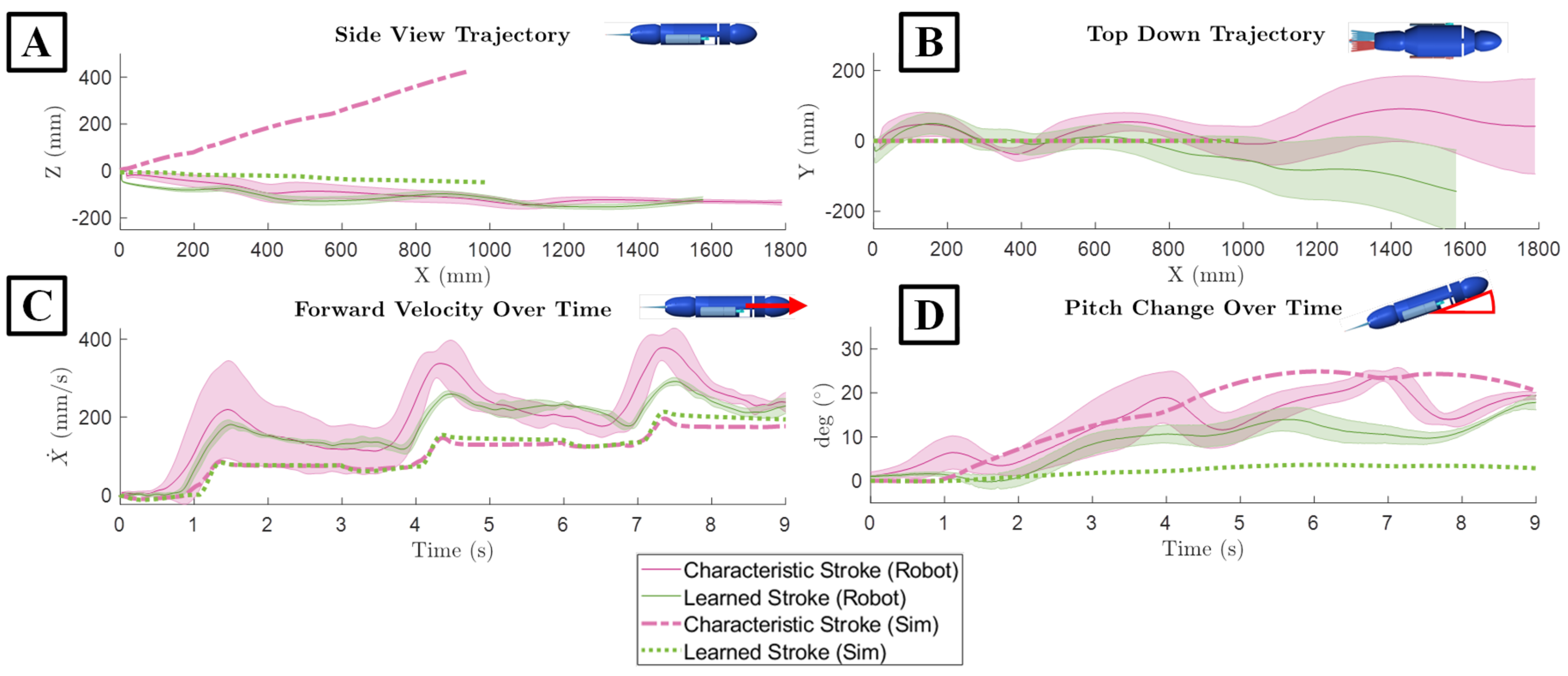
When applied to the numerical simulation, the learned stroke outperformed the characteristic stroke in terms of maintaining heading, total forward distance traveled, and forward velocity. The maximum recorded change in heading in the learned stroke was 3.6° with a mean of 2.2°. For the characteristic stroke, the maximum change in heading was 24.9°, which was 44.5% higher than the change in heading produced during the learned stroke [
Figure 11D]. When looking at the maximum distance travelled in the x direction, the learned stroke travelled 991 mm in 9 seconds which was 5.7% higher than the biological stroke over the same time interval [
Figure 11A,B] Additionally, the learned stroke from the numerical model exhibited an average velocity of 110 mm/s, peaking at 213 mm/s. In contrast, the characteristic stroke produced an average velocity of 104 mm/s, with its peak at 195 mm/s [
Figure 11C].
The comparison between the learned and characteristic strokes reveals distinct differences in vertical displacement, despite similar negligible lateral movements. For both strokes, the distance traveled in the Y direction, which was the lateral direction, was very close to zero [
Figure 11B]. However, the largest difference between the two strokes was present in the change in the Z direction, or the vertical direction. The learned gait resulted in a final distance traveled down in Z direction 49.4 mm, while the characteristic stroke resulted in a much larger change upwards in the Z direction of 422 mm [
Figure 11A].
3.3. Strokes Applied on Bio-Robotic Platform
When applied to the bio-robotic sea lion platform, the characteristic stroke and the learned stroke exhibited closely matched performance, with the characteristic stroke traveling the farthest distance and maintaining the highest velocity, and the learned stroke resulting in a more level and consistent swimming path. The mean distance travelled in the x direction for the learned stroke was 1570 mm which was only 14.2% lower than the biologically derived stroke which traveled 1790 mm [
Figure 11A]. The learned stroke when applied to the bio-robotic system exhibited an average linear velocity in x direction of 175 mm/s with a peak at 364 mm/s [
Figure 11]. This was again only 13.5% slower than the robotic system swimming with the characteristic stroke with a mean velocity of 197 mm/s and peak velocity of 414 mm/s [
Figure 11]. When examining changes to the lateral direction, both strokes resulted in less straight swimming paths than in simulation [
Figure 11]. The learned stroke resulted in a mean displacement of 26.6 mm in the negative y direction at the end of the trials. On the other hand, the characteristic stroke moved in the positive y direction with a mean of 22.4 mm [
Figure 11]. The maximum movement in the z direction was nearly identical for both strokes, measuring -152.8mm which was only 5% lower in the characteristic stroke, where it reached 144.3mm on average [
Figure 11]. In the context of the heading of the bio-robotic system, the learned stroke had a mean of only 8.5° with a maximum of 17.9°. In contrast, the average heading in the characteristic stroke was 13.2° which was 55.3% higher, and its maximum heading reached 23.8°, representing a 32% increase when compared to the learned stroke [
Figure 11].
3.4. Differences between Numerical and Bio-Robotic Models
When comparing the numerical simulation with the bio-robotic system both the learned stroke and the biological-derived stroke, traveled further and faster when applied to the physical robot than in simulation but the swimming path was less straight. There was an increase of 45.6% distance traveled in the x direction by the bio-robotic system resulting from the learned stroke compared to the numerical simulation. Similarly, there was an increase of 62.5% in total forward distance traveled from the characteristic stroke as well [
Figure 11]. Also, the maximum forward velocity achieved increased by 31% for the learned stroke and 63.9% for the characteristic stroke when applied to the physical system [
Figure 11C]. However, the maximum heading observed in the numerical model when the learned stroke was used was 3.1° with an average of 1.9° which was significantly lower than the bio-robotic system which had a maximum of 17.9° with a mean of 8.5° [
Figure 11D]. The resulting pitch from the characteristic stroke applied to the physical robot was like that which occurred in the numerical simulation, a maximum change in heading being 23.7° and 24.9° respectively. In the lateral direction, the mean distance was close to 0 in the numerical simulation, but there was some deviation in the lateral direction with the physical robot [
Figure 11D]. The bio-robotic system moved in the lateral direction a maximum of 143 mm due to the learned stroke and 91.1 mm due to the characteristic stroke. Additionally, in the Z direction, the behavior of the bio-robotic system was different than in simulation [
Figure 11]. The learned stroke resulted in a deviation along the z axis of 152 mm when applied to the bio-robotic system compared to only 48 mm in simulation. Conversely the characteristic stroke had less deviation along the Z axis, only going up by 144 mm compared to 422 mm in simulation, although this was likely due to the surface of the water stopping any further increase along that axis [
Figure 11].
4. Discussion and Conclusions
The reinforcement learning-based approach not only showed success in generating an effective swimming gait in simulation but also retained its effectiveness when deployed in real world testing. With just an outline for a characteristic stroke, reinforcement learning produced a new swimming gait specifically tailored to the dynamics of the bio-robotic sea lion model. This approach created a stroke that demonstrated smooth, straight-line swimming when deployed on the physical system.
The learned gait outperformed the biologically derived stroke in several crucial metrics in simulation: it achieved higher peak velocities, covered greater distances, and maintained a more linear trajectory. When implemented on the bio-robotic platform, the learned gait continued to perform well, consistently traveling 12.7% of the distance and maintaining a mean velocity within 12.2% of the characteristic gait, while adhering to a straighter path. Additionally, the learned stroke exhibited a superior level of consistency across multiple trials in three-dimensional space, again outperforming its characteristic biologically derived counterpart in terms of repeatability. Despite these differences in performance between the two gaits, it is important to underscore that both strokes are effective for swimming, and each presents unique advantages that could be useful for different applications.
Both the learned and characteristic gaits demonstrated enhanced speed and travel distance when implemented on the physical system. However, this performance improvement was accompanied by shortcomings, including reduced roll-axis stability, decreased consistency, and less straight trajectories. Several factors may have contributed to the differences between the numerical model and experimental platform. As an example, the robot included a supporting structure for the infrared reflective spheres, which, despite representing a minor portion of the system’s overall dry mass, may have introduced unanticipated dynamics that were not accounted for in the simulation. Additionally, non-uniform mass distribution along the core axes, potential foreflipper induced force imbalances, hydrodynamic forces acting on the body, and improper tuning of the center of mass and center of buoyancy might have collectively contributed to the differences observed in swimming performance between both models. Another potential difference in these systems could be attributed to an overestimation of inertial attributes and fluidic added mass in the simulation. Furthermore, the characteristic stroke’s inclination to pitch the robot upward gained inadvertent advantages from its near-surface positioning during real-world tests. In contrast to the simulation where continuous upward pitching is possible, the actual bio-robotic system would surface and then submerge again. This benefit did not similarly extend to the learned stroke, as it was less prone to pitch upwards.
Both the numerical and physical models were sensitive to buoyancy and gravitational forces. The center of mass always moves directly under the center of buoyancy, so proper alignment for the desired operating orientation is critical. Fortunately, achieving neutral buoyancy and controlling the locations of the centers of mass and buoyancy were straightforward tasks in the numerical model. However, this was much more challenging in the physical robot. Despite significant efforts to achieve neutral buoyancy in the bio-robotic system, predicting the exact locations of the centers of mass and buoyancy in the real-world system proved difficult. Misalignment of these centers could contribute to discrepancies in pitch angle between the simulation and the physical system’s gait performance. Future work should focus on achieving better control over the centers of mass and buoyancy in the robotic system.
Future endeavors should concentrate on calibrating the weight distribution and internal dynamics of the physical system to better align it with simulation predictions. Also, both the simulation and physical system possess additional degrees of freedom, including a head, pelvic section, and two pelvic flippers. Exploring how to coordinate these elements to achieve a more stable gait will be important. Exploring different initial conditions, such as different starting orientations, different initial velocities, or operating over longer time scales is another potential avenue for future work. Another point to consider is that all tests commenced from a standstill, which does not replicate the initial conditions of a sea lion’s natural propulsive clap that the characteristic stroke aims to mimic.
The reinforcement learning approach, while promising, exhibited several areas where the learning structure could be refined to improve the resulting gaits. One potential area for enhancement is the reward function. Each of the factors considered in the reward function (forward velocity, heading, angular velocity, and distance traveled forward) were equally weighted in these experiments. Using an optimization technique such as Bayesian optimization or a genetic algorithm to refine the reward function weights could lead to improved gait outcomes. Weighting the distinct factors of the reward function will influence the resulting movements; when the weights are equal it is possible that some terms were overrepresented in their impact on the final behaviors. Another potential area for improvement is the lack of an efficiency metric within the reward function, affecting gait performance. The current setup may also benefit from structural changes, such as increasing the number of steps per training episode. This could enable the algorithm to develop more effective policies that are applicable over a broader range of states, allowing it to act as a continuous controller rather than a trajectory generator. Moreover, although not within the scope of the present study, other gait development methods like genetic algorithms, various alternate types of reinforcement learning agents such as Deep Deterministic Policy Gradients (DDPG) or Proximal Policy Optimization (PPO), and bio-inspired techniques like Central Pattern Generators could be explored.
Reinforcement learning, when applied to complementary bio-robotic and numerical models of a California sea lion, exhibits promise in the development of new and effective swimming gaits. Gaits could further be enhanced with improved alignment of system dynamics of both the numerical model and the bio-robotic platform. Further tuning the reward function holds the potential for both improved gait performance and the adaptation of diverse gaits for specific tasks such as a slow-moving gait or maintaining a constant velocity. Despite these limitations, the success of the learned gait in outperforming the biologically derived stroke in simulation and its comparable performance on the bio-robotic system demonstrate the potential of this approach to learn additional effective swimming gaits.
Author Contributions
Conceptualization, A.D., S.K., N.M., J.L.T.; methodology, A.D., S.K., N.M., J.L.T; software A.D., S.K.; formal analysis A.D.; investigation, A.D., S.K., N.M.; resources J.L.T., H.G.K.; supervision J.L.T., H.G.K.; writing—original draft preparation A.D., S.K., N.M.; writing—review and editing A.D., S.K., N.M., J.L.T., H.G.K.; visualization, A.D.; project administration, A.D. and J.L.T.; funding acquisition, J.L.T., H.G.K. All authors of this manuscript have directly participated in the planning, execution, and/or analysis of this study. The contents of this manuscript have not been copyrighted or published previously. All authors have no objection to the ranking order. All authors have read and agreed to the published version of the manuscript.
Funding
This research was funded by the Office of Naval Research (Tom McKenna, Program Manager, ONR 341).
Data Availability Statement
The data generated during the study are available from the corresponding author on reasonable request.
Acknowledgments
This work is a result of a collaboration with Dr Frank Fish of West Chester University and Dr Meghan Leftwich of George Washington University. The authors would like to thank the collaborators for providing insight on the biological system and access to countless sea lion videos from the National Smithsonian Zoo, Washington, DC.
Conflicts of Interest
The authors declare no conflicts of interest.
References
- Wibisono, M. J. Piran, H. K. Song, and B. M. Lee, “A Survey on Unmanned Underwater Vehicles: Challenges, Enabling Technologies, and Future Research Directions,” Sensors, vol. 23, no. 17, p. 7321, Aug. 2023. [CrossRef] [PubMed] [PubMed Central]
- D. Weihs, “Stability Versus Maneuverability in Aquatic Locomotion,” Integrative and Comparative Biology, vol. 42, no. 1, pp. 127–134, Feb. 2002. [CrossRef]
- Wibisono, M. J. Piran, H. K. Song, and B. M. Lee, “A Survey on Unmanned Underwater Vehicles: Challenges, Enabling Technologies, and Future Research Directions,” Sensors, vol. 23, no. 17, p. 7321, Aug. 2023. [CrossRef] [PubMed] [PubMed Central]
- R. K. Katzschmann, J. Delpreto, R. Maccurdy, and D. Rus, “Exploration of underwater life with an acoustically controlled soft robotic fish,” 2018. [Online]. Available online: http://robotics.sciencemag.org/.
- P. Mignano, S. Kadapa, J. L. Tangorra, and G. V. Lauder, “Passing the Wake: Using Multiple Fins to Shape Forces for Swimming,” Biomimetics, vol. 4, no. 1, Mar. 2019. [CrossRef]
- J. Tangorra, C. Phelan, C. Esposito, and G. Lauder, “Use of biorobotic models of highly deformable fins for studying the mechanics and control of fin forces in fishes,” Integrative and Comparative Biology, pp. 176–189, Jul. 2011. [CrossRef]
- M. A. Soliman, M. A. Mousa, M. A. Saleh, M. Elsamanty, and A. G. Radwan, “Modelling and implementation of soft bio-mimetic turtle using echo state network and soft pneumatic actuators,” Scientific Reports, vol. 11, no. 1, Dec. 2021. [CrossRef]
- J. Zhang, Y. Chen, Y. Liu, and Y. Gong, “Dynamic Modeling of Underwater Snake Robot by Hybrid Rigid-Soft Actuation,” Journal of Marine Science and Engineering, vol. 10, no. 12, Dec. 2022. [CrossRef]
- F. E. Fish, J. Hurley, and D. P. Costa, “Maneuverability by the sea lion Zalophus californianus: turning performance of an unstable body design,” Journal of Experimental Biology, vol. 206, no. 4, pp. 667–674, Feb. 2003. [CrossRef]
- S. D. Feldkamp, “Foreflipper propulsion in the California sea lion, Zalophus californianus,” 1987.
- J. Tan et al., “Sim-to-Real: Learning Agile Locomotion For Quadruped Robots,” 2018.
- D. Rodriguez and S. Behnke, “DeepWalk: Omnidirectional Bipedal Gait by Deep Reinforcement Learning,” 2021.
- G. Chen, Y. Lu, X. Yang, and H. Hu, “Reinforcement learning control for the swimming motions of a beaver-like, single-legged robot based on biological inspiration,” Robotics and Autonomous Systems, vol. 154, Aug. 2022. [CrossRef]
- I. Carlucho, M. De Paula, C. Barbalata, and G. G. Acosta, “A reinforcement learning control approach for underwater manipulation under position and torque constraints,” in 2020 Global Oceans 2020: Singapore - U.S. Gulf Coast, Institute of Electrical and Electronics Engineers Inc., Oct. 2020. [CrossRef]
- A. Drago, G. Carryon, and J. Tangorra, “Reinforcement Learning as a Method for Tuning CPG Controllers for Underwater Multi-Fin Propulsion,” in Proceedings - IEEE International Conference on Robotics and Automation, Institute of Electrical and Electronics Engineers Inc., 2022, pp. 11533–11539. [CrossRef]
- H. Ju, R. Juan, R. Gomez, et al., “Transferring policy of deep reinforcement learning from simulation to reality for robotics,” Nature Machine Intelligence, vol. 4, pp. 1077–1087, 2022. [CrossRef]
- M. Körber, J. Lange, S. Rediske, S. Steinmann, and R. Glück, “Comparing Popular Simulation Environments in the Scope of Robotics and Reinforcement Learning,” arXiv, 2021. Available online: https://arxiv.org/abs/2103.04616.
- T. I. Fossen, “Guidance and Control of Ocean Vehicles,” 1995.
Figure 1.
Bio-robotic and Numerical Model of the California Sea lion for Reinforcement Learning. Using the California Sea lion as model, complementary numerical and bio-robotic models were constructed utilizing the observed important degrees of freedom present in the animal. The propulsive kinematics were replicated, and reinforcement learning was applied in simulation to further modify the kinematics for direct use on the bio-robotic system.
Figure 2.
Flipper and Body Frame of Sea Lion Model. (A) The flipper and body frames of the sea lion model. (B) Specific orientation of the flipper frame.
Figure 2.
Flipper and Body Frame of Sea Lion Model. (A) The flipper and body frames of the sea lion model. (B) Specific orientation of the flipper frame.
Figure 3.
The Sea Lion Characteristic Stroke Flipper Frame Kinematics. (A) Side view and (B) Bottom view of the Sea Lion executing its characteristic fore flipper stroke. (C) Side View and (D) Front View of modeled kinematics executing the characteristic fore flipper stroke in simulation.
Figure 3.
The Sea Lion Characteristic Stroke Flipper Frame Kinematics. (A) Side view and (B) Bottom view of the Sea Lion executing its characteristic fore flipper stroke. (C) Side View and (D) Front View of modeled kinematics executing the characteristic fore flipper stroke in simulation.
Figure 4.
Spline Model of the Characteristic Sealion Stroke. The pitch, yaw, and roll angles of the characteristic sea lion propulsive stroke. The red dots are the control points that the Piecewise Cubic Hermite Interpolating Polynomial (PCHIP) is fit to.
Figure 4.
Spline Model of the Characteristic Sealion Stroke. The pitch, yaw, and roll angles of the characteristic sea lion propulsive stroke. The red dots are the control points that the Piecewise Cubic Hermite Interpolating Polynomial (PCHIP) is fit to.
Figure 5.
The Bio-robotic and Numerical Model of the California Sea Lion. (A) The California sea lion making use of its flippers and body to execute a maneuver. (B) The bio-robotic sea lion model with all the degrees of freedom selected to model the motions of the sea lion. (C) The Numeric model representation of the bio-robotic model.
Figure 6.
Drag Simulations of the Sea Lion Numerical Model. (A) CFD simulation to determine the coefficient of drag of the sea lion model (B) Strip theory division of the body for calculating drag in the y and z directions.
Figure 6.
Drag Simulations of the Sea Lion Numerical Model. (A) CFD simulation to determine the coefficient of drag of the sea lion model (B) Strip theory division of the body for calculating drag in the y and z directions.
Figure 7.
Structure of the Actor and Critic Networks and the Hyperparameters: Architecture of the (A) Actor network and the (B) Critic network used in the Soft Actor Critic (SAC) agent and the (C) hyperparameters.
Figure 7.
Structure of the Actor and Critic Networks and the Hyperparameters: Architecture of the (A) Actor network and the (B) Critic network used in the Soft Actor Critic (SAC) agent and the (C) hyperparameters.
Figure 8.
Action and Observation Space for the Reinforcement Learning Environment (A) The 13 Actions that control the shape, magnitude, and timing of the PCHIP spline model the fore flipper kinematics (B) The Observation space the defines the motion of the sea lion model to the reinforcement learning agent.
Figure 9.
Testing Set-up. (A) The motion tracking cameras are affixed over the testing pool (B) IR reflective balls are placed on a structure that will stick out of the water for tracking.
Figure 9.
Testing Set-up. (A) The motion tracking cameras are affixed over the testing pool (B) IR reflective balls are placed on a structure that will stick out of the water for tracking.
Figure 10.
Side Profile of Propulsive Flipper Strokes in Simulation and on the Bio-robotic Model. (A) Biologically derived characteristic stroke in simulation and (B) on the bio-robotic system. (C) Reinforcement learning derived stroke in simulation and (D) on the bio-robotic system.
Figure 10.
Side Profile of Propulsive Flipper Strokes in Simulation and on the Bio-robotic Model. (A) Biologically derived characteristic stroke in simulation and (B) on the bio-robotic system. (C) Reinforcement learning derived stroke in simulation and (D) on the bio-robotic system.
Figure 11.
Propulsive Performance of the Biologically Derived and the Learned Strokes in Simulation and on the Physical Robotic Platform. (A) Motion in the X-Z plane. (B) Motion in the X-Y plane. (C) Forward velocity over time. (D) Change in pitch over time.
Figure 11.
Propulsive Performance of the Biologically Derived and the Learned Strokes in Simulation and on the Physical Robotic Platform. (A) Motion in the X-Z plane. (B) Motion in the X-Y plane. (C) Forward velocity over time. (D) Change in pitch over time.
|
Disclaimer/Publisher’s Note: The statements, opinions and data contained in all publications are solely those of the individual author(s) and contributor(s) and not of MDPI and/or the editor(s). MDPI and/or the editor(s) disclaim responsibility for any injury to people or property resulting from any ideas, methods, instructions or products referred to in the content. |
© 2024 by the authors. Licensee MDPI, Basel, Switzerland. This article is an open access article distributed under the terms and conditions of the Creative Commons Attribution (CC BY) license (https://creativecommons.org/licenses/by/4.0/).
