Preprint
Article

A Novel Mixed Finite/Infinite Dimensional Port-Hamiltonian Model of a Mechanical Ventilator

Altmetrics

Downloads

90

Views

24

Comments

0

A peer-reviewed article of this preprint also exists.

Submitted:

27 May 2024

Posted:

28 May 2024

You are already at the latest version

Alerts
Abstract
Mechanical ventilation is a life-saving treatment for critically ill patients who are struggling to breathe independently due to injury or disease. Globally, large numbers of Individuals have always required mechanical ventilation per year. The Covid-19 pandemic elevated the significance of the mechanical ventilation which have played a significant role in sustaining Covid 19 infected critically ill patients who could not breathe on their own. The pandemic drew the attention of the world to the shortage of ventilators globally.This research work presents the formulation of a detailed Port Hamiltonian model of a mechanical ventilator integrated to the human respiratory system. The interconnection and coupling conditions for the various subsystem within the mechanical ventilator and the coupling between the mechanical ventilator and the human respiratory system is also presented.A structure preservation discretization is provided along side numerical simulations and results. The obtained results are found to be comparable to results presented in literature.The future work will include the design of suitable controllers for system.
Keywords: 
Subject: Engineering  -   Control and Systems Engineering

1. Introduction

The World Health Organization (WHO) has "access to oxygen" on its model list as one of the essentials required by an individual, especially when they are in a critical condition health-wise and they are unable to breathe on their own. Access to oxygen is the only medicine listed that does not have a substitute. Access to oxygen even after the worldwide pandemic is still a major dilemma in middle and low-income countries [1]. A mechanical ventilator is a medical device that is employed in assisting patients in cases where their respiratory system is not functioning well, thus the patient has challenges in breathing or has shortness of breath. The mechanical ventilator can also be used in cases where a patient has been sedated and is undergoing surgery.
The basic operation of a mechanical ventilator is to control a high-pressure region during the inspiration stage. In the inspiration stage, the mechanical ventilator is paused. During expiration, air flows out due to the lung’s natural recoil which creates a higher pressure in the alveoli. Due to the high demand for mechanical ventilators both in the past and at present, it is imperative that efficient and affordable mechanical ventilators should be researched, modelled, designed and implemented. To ensure that robust mechanical ventilators are designed, it is important to formulate new models that can be used in the research and testing stages of the mechanical ventilators.

2. Related works

Tran et al, [2], conducted research whose main goal was to design, control, model, and simulate a mechanical ventilator that is light in weight, portable, and suitable for use at home. [2], modelled the mechanical ventilator as a voltage source. El-Hadj et al [3], applied the fluid-structure Interaction (FSI) to a couple of computational fluid dynamics used for fluid flow with finite element analysis for the solid domain. This facilitated the investigation of fluid behaviour, structural behavior, and interactions. Two designs were proposed for the mechanical ventilator. The first design was reported to be uncontrollable and the second design considers Computational Fluid Dynamics (CDF) with a moving boundary which is applied to the piston cylinder based ventilator. Tharton et al [4], designed and developed a ventilator prototype to be used by professionals in medical emergencies and in any other context where the regular ventilator is not available. The mechanical ventilator was modelled using the crank rocker mechanism in order to meet specific requirements for mechanical ventilator design. Pivk et al, [5], developed an empirical model for a low-cost mechanical ventilator by observing the response of each of the ventilator subsystems. The current progress made globally in the development of affordable and effective designs is important. However, research in mechanical ventilator development lacks model development. The Port-Hamiltonian approach applied in this research work acts as a modelling template for future energy-based mechanical ventilator modelling and design. It is important to develop designs that rest on a solid understanding of a significant aspect of the design. Naggar, [6] developed a piecewise model of a mechanical ventilator which described the artificial behaviour of a mechanical ventilator. A pressure-controlled ventilator is created and simulated. The mechanical ventilator is modelled using a periodic function with inequalities to control the beginning of inspiration and expiration periods. Shi et al, [7] developed a mathematical model of volume-controlled mechanical ventilation. The model is viewed as a pneumatic system where the ventilator is regarded as an air compressor. The exhalation valve is considered as throttle. The compressor and the container represent the ventilator. Naggar et al, [8] proposed an integrated mathematical model of the mechanical ventilator and the lung. Linear quadratic and exponential equations were used to model the system. The integrated model was used to simulate volume-controlled artificial ventilation. Giri et al, [9], proposed a simplified design of a mechanical ventilator, to reduce cost and automate the mechanical ventilation process. The proposed design was simulated on the MATLAB platform. Hannon et al, [10] presented a review on the advancement in the modelling of human anatomy, physiology and pathophysiology via mathematical modelling and computer simulation. Clinical applications in various disease states were emphasized. The research work discussed the current limitations and potential of in-silico modelling. There are currently no existing Port Hamiltonian models of mechanical ventilators intergrated with a human repiratory system. The main contribution in this research work is the development of an intergrated Port-Hamiltonian model representation of a mechanical ventilator-human respiratory system. The model consists of electromechanical and electromagnetic components modelled in the finite-dimensional representation, interconnected with fluid components in the infinite-dimensional representation. As a result, this Port-Hamiltonian model is of a mixed finite/infinite dimensional nature.

3. Materials and Method

This section presents the mathematical preliminaries of the Port Hamiltonian approach that have been followed in later sections. These definitions are standard definitions from literature and are mostly derived from the following references: [11,12] and [13]
Definition 1 (Dirac Structure)
A Dirac Structure (DS) is a pair of elements, f R n and e R n , that satisfies the set:
D ( f , e ) D , ( f ^ , e ^ ) D e T f ^ = e ^ T f
The DS is a subset D F × E , where F and E represent the flows and efforts, respectively.
The DS in electric circuits can be represented as:
Proposition 1:
The subspace
D R n × R n
is called a DS iff, there exist A , B R n × n such that
A B T + A B T = 0 and rank ( [ A B ] ) = n
satisfying the condition
D = ( f , e ) R n × R n | A f = B e
Definition 2 (Resistive Relation)
Any relation R R n × R n is said to be resistive if ( f R , e R ) R the
e R T f R 0
is satisfied.
Definition 3 (Port-Hamiltonian (pH) System).
The set ( D , L , R ) , defines a pH system where:
  • D ( F L × F R × F P ) × ( E L × E R × E P ) is a DS
  • L F L × E L is a LS and
  • R F R × E R a Resistive relation.
The elements of the sets:
  • F L R n L and E L R n L are known as flows and efforts
  • F R R n R and E R R n R are known as resistive flows and efforts
  • F P R n P and E P R n P are known as external flows and efforts, respectively.
where n L , n R and n P N 0 .
The dynamics of the pH system are given by the differential inclusion
d d t x ( t ) , f R ( t ) , f P ( t ) , e L ( t ) , e R ( t ) , e P ( t ) D
where ( x ( t ) , e L ( t ) ) L , ( f R ( t ) , e R ( t ) ) R and ( f P ( t ) , e P ( t ) ) P
Definition 4 (Interconnection of n pH Systems)
Let ( D i , L i , R i ) denote the space of the i th pH system in a set of n pH systems that are to be interconnected. The space of flows is divided into an external part and a part to be linked and is given by
F i = F L i × F R i × F P i × F P link
Similarly, the space of efforts is divided into an external part and a part to be linked and is expressed as
E i = F L i × E R i × E P i × E P link
The interconnection of two pH systems ( D 1 , L 1 , R 1 ) and ( D 2 , L 2 , R 2 ) with respect to the link ( F P link , E P link ) results in a new interconnected pH system, ( D , L , R ) . This interconnected system is given by the expression
( D 1 , L 1 , R 1 ) ( D 2 , L 2 , R 2 ) ( D , L , R )
Definition 5 (Directed Graph).
A directed graph is a quadruple G ( V , E , l , r ) where
  • V is a set of vertices
  • E is a set of edges
  • l : E V maps each edge, e, to an initial vertex
  • r : E V maps each edge, e, to a terminal vertex
Definition 5.1 (Loop-free directed Graph).
If G is a directed graph, then G is said to be loop-free if for all e E ,
l ( e ) r ( e )
Definition 5.2 (Subgraphs).
Given the graphs G ( V , E , l , r ) and G ( V , E , l , r ) , then G is said to be a subgraph of G if E E and V V . Furthermore,
  • A subgraph is said to be an induced subgraph on V if E = E | V
  • A subgraph is said to be spanning if V = V
  • A subgraph is said to be a proper subgraph if E E
  • If both V and E are finite, then G is said to be finite
Definition 6 (Paths, Connectivity and Cycles).
Let G = ( V , E , l , r ) be a directed finite graph.
  • An n-tuple e = ( e 1 , , e n ) ( E E ) n is called a path from υ to ϖ , if
    (a)
    l ( e 1 ) , , l ( e n ) are distinct
    (b)
    r ( e i ) = l ( e i + 1 ) for all i 1 , , n 1
    (c)
    l ( e 1 ) = υ r ( e n ) = ϖ
  • A path from υ to υ is called a cycle.
  • Two vertices, υ and ϖ are said to be connected if there exists a path from υ to ϖ .
  • The existence of paths from vertices gives an equivalence relation on the set of vertices.
  • A subgraph is a component of the graph.
  • A graph with only one component is said to be connected.
Definition 7 (Incidence Matrix).
Let G = ( V , E , l , r ) be a directed graph that is finite and loop-free such that E = e 1 , , e m and V = υ 1 , , υ n . Then the j t h row and k t h columns of the incidence matrix, A 0 R n × m of G is given by
a j k = 1 l ( e k ) = υ j , 1 r ( e k ) = υ j , 0 otherwise .
If the rank ( A 0 ) = n k , then the graph G has k N components, such that k rows can be removed from A 0 resulting in matrix with same rank.
Definition 8 (Kirchhoff-Dirac Structure, Kirchhoff-Lagrange Submanifold).
The Kirchhoff-Dirac structure of G can thus be defined by the set
D K S ( G ) ( j , i , ϕ , u ) R n | S | × R m × R n | S | × R m I A 0 0 j i + I A 0 0 ϕ u = 0
where i and u are the currents and voltages at the edges of the graph, respectively, whereas q and ϕ are the charges and potentials at the vertices of the graph, respectively.
Assuming that S = v 1 , , v | S | , the Kirchhoff-Lagrange submanifold of G with respect to S is defined as
L K S ( G ) 0 × R n | S | R n | S | × R n | S |
where G = ( V , E , l , r ) is a directed graph that
  • Is finite
  • Is loop-free
  • Has an incidence matrix A 0 R n × m
If G 1 , , G k are the components of G with corresponding vertices V 1 , , V k V so that there exists a subset S V such that S containing at most one vertex from each component, i.e. s , s , S , i k : v , v V i v = v , then A R ( n k ) × m can be constructed by deleting the rows corresponding to the vertices S from A 0 R n × m .
Remark. According to Proposition 1, Equations 1 and 2 indicate that D K S ( G ) is a DS and L K S ( G ) is a LS in the space R n | S | × R n | S | .
Definition 8 caters for an introduction of a pH system ( D K S ( G ) , L K S ( G ) , 0 ) with dynamics
( d d t q ( t ) , i ( t ) , ϕ ( t ) , u ( t ) ) D K S ( G )
where ( q ( t ) , ϕ ( t ) ) L K S ( G ) .
Using the equivalence of ( q ( t ) , ϕ ( t ) ) L K S ( G ) to q ( t ) = 0 and ϕ ( t ) R n | S | , we see that equation 3 holds, iff, the condition holds.
q ( t ) = 0 A i ( t ) = 0 A T ϕ 2 ( t ) = u ( t ) .
b j l = 1 e l C j with orientations that coincide , 1 e l C j with orientations that do not coincide , 0 otherwise
On this basis, one can define a DS
D K ( G ) ( j , i , ϕ , u ) R n | S | × R m × R n | S | × R m I A 0 0 j i + I A 0 0 ϕ u = 0
with dynamics
d d t ψ ( t ) , i ( t ) , ι ( t ) , u ( t ) D K ( G )
and an LS
L K ( G ) 0 × R n m + k
with dynamics
ψ ( t ) , ι ( t ) L K ( G )
Together, they form a the pH system defined by the set ( D K ( G ) , L K ( G ) , 0 ) .

3.1. Dirac Structure

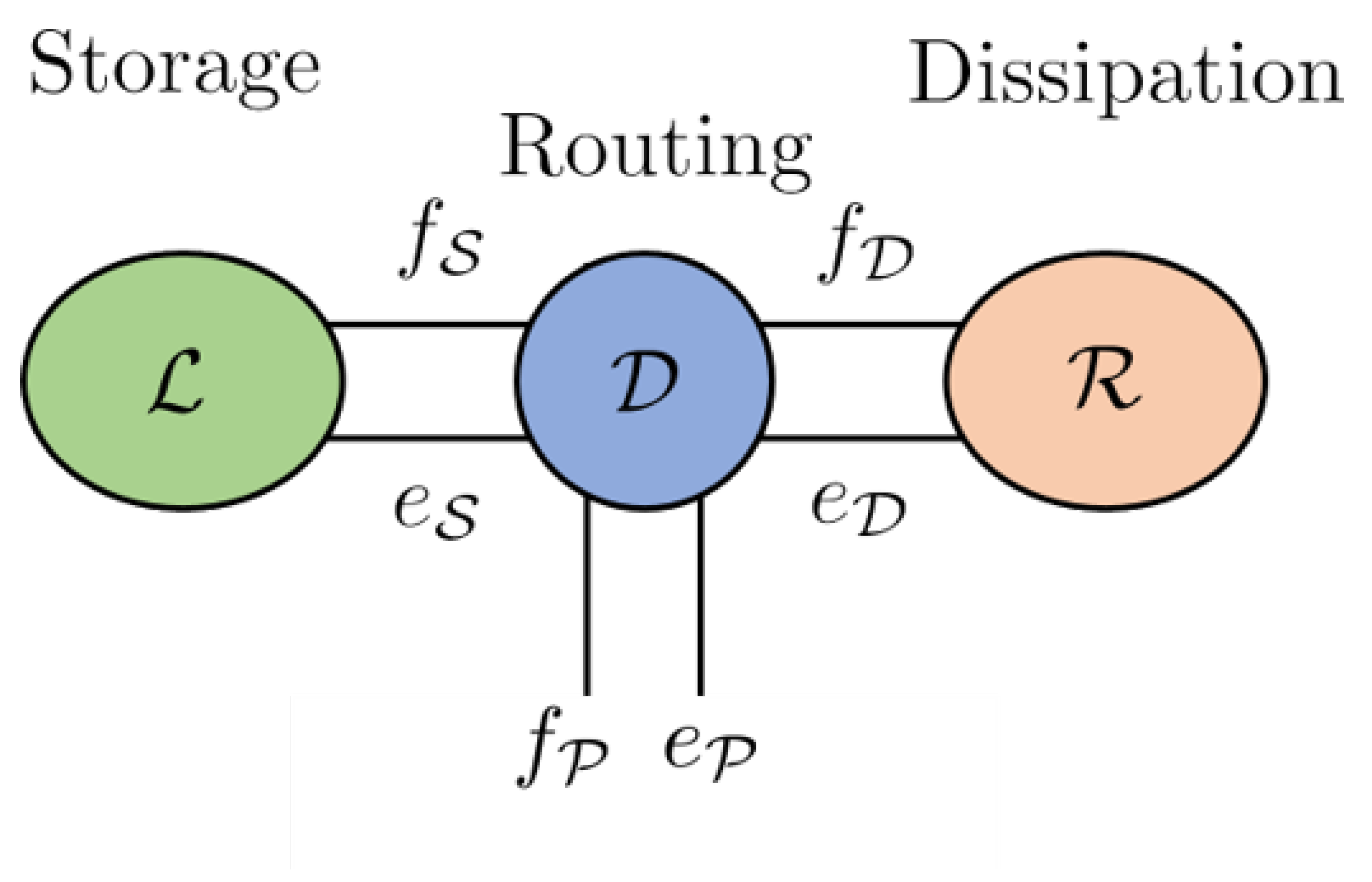
A key feature of a Dirac structure is the fact that the standard composition of two Dirac structures is again a Dirac structure. The implication of this statement is that any power-conserving interconnection of a Port Hamiltonian system is also a Port Hamiltonian system itself. This constitutes the foundation feature in the Port Hamiltonian approach to modelling, simulation and control of complex physical systems. The intricate Dirac structure is the guide to the algebraic constraints of the interconnected system as well as its Casimir functions [13]. The Casimir are significant in the set point regulation of Port Hamiltonian systems. The framework for the Port Hamiltonian allows for port-based modelling. Port-based modelling means that we are interconnecting many different elements through ports. Dirac structures are the tools used to connect multiple elements. These various elements are energy-storing elements, energy-dissipating elements and external elements which could be supplying energy. A diagram to demonstrate the connection structure is given in Figure 1,13]

4. Detailed Port-Hamiltonian Model of a Mechanical Ventilator

4.1. Description of the System

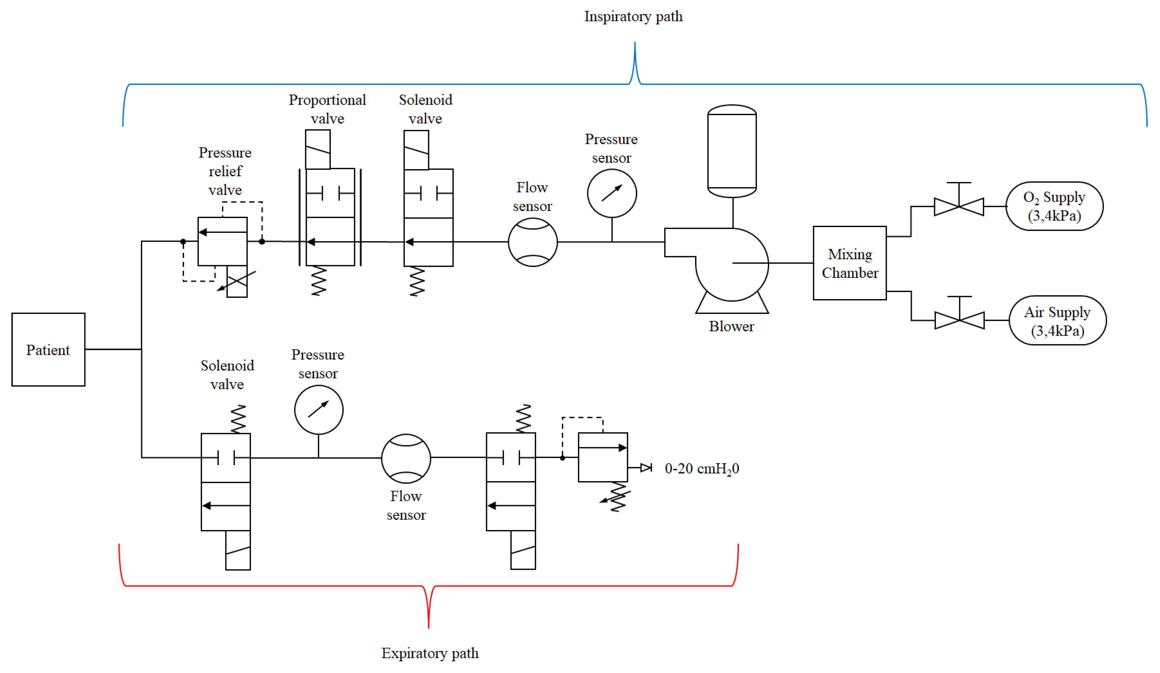
The overall mechanical ventilator system diagram is provided in Figure 2. The entire system consists of various subsystems. In this research work, the main subsystem that contributes to the flow of air and consequently the air pressure are discussed. Therefore, the following main subsystems will be discussed: the DC Motor subsystem, Turbine pump/blower subsystem, Pump-shaft/impeller subsystem and Solenoid valve subsystem,

4.2. Blower Model

In this section, the dynamical system model equations for the blower model are presented in the port-Hamiltonian framework. The blower model comprises three sub-systems, namely a DC Motor which drives the blower-shaft/impeller, a blower-shaft/impeller that couples the DC motor to the fluid, using the rotational motion of the motor to accelerate the fluid and finally the fluid being driven.
In the Port-Hamiltonian perspective, the state vector X b R 4 , given by
X b p m , ϕ m , P b , Q b
where p m R 1 and ϕ m R 1 are the angular momentum and magnetic flux of the DC motor, respectively, while P b R 1 and Q b R 1 are the pressure and flow rate of the blower.
The total energy of the blower is given by the Hamiltonian
H b X b = 1 2 p m 2 I m + ϕ m 2 L m + C b P b 2 + I b Q b 2
where I m R + 1 is the inertia and L m R + 1 is the inductance of the DC motor, while C b R + 1 and I b R + 1 is the hydraulic capacitance and inertance of the air in the blower, respectively.
Thus, the Port-Hamiltonian model of a blower is given by
X ˙ b = J b R b H b X b + G b u b
Y b = G b * H b X b
where
J b 0 K m 0 ( K o p m ) / I m K m 0 0 0 0 0 0 1 / ( C b I b ) ( K o p m ) / I m 0 1 / ( C b I b ) 0 R 4 × 4 R b diag b m R m 0 ( R b p m ) / ( I b I m ) R 4 × 4 H b X b p m / I m ϕ m / L m C b P b I b Q b R 4 × 1 G b 1 0 0 0 0 0 0 ( 1 / C b ) 0 0 0 ( 1 / I b ) R 4 × 3 u b V m Q i n P i n R 3 × 1
where K m R + 1 is the motor torque constant, b m R + 1 is the viscous damping, R m R + 1 is the armature resistance and K o R + 1 is the motor angular momentum/pressure coupling constant. The inputs to the system are the DC motor voltage, the input volumetric flow rate and pressure given by V R 1 , Q i n R 1 and P i n R 1 . One can easily show that J m = J m and R m = R m 0 .
Taking the time derivative of the Hamiltonian
H ˙ b [ χ b ] = u b · Y b H b [ X b ] · ( R b H b [ X b ] )
This system has power and resistive ports.

5. Solenoid Valve Subsystem

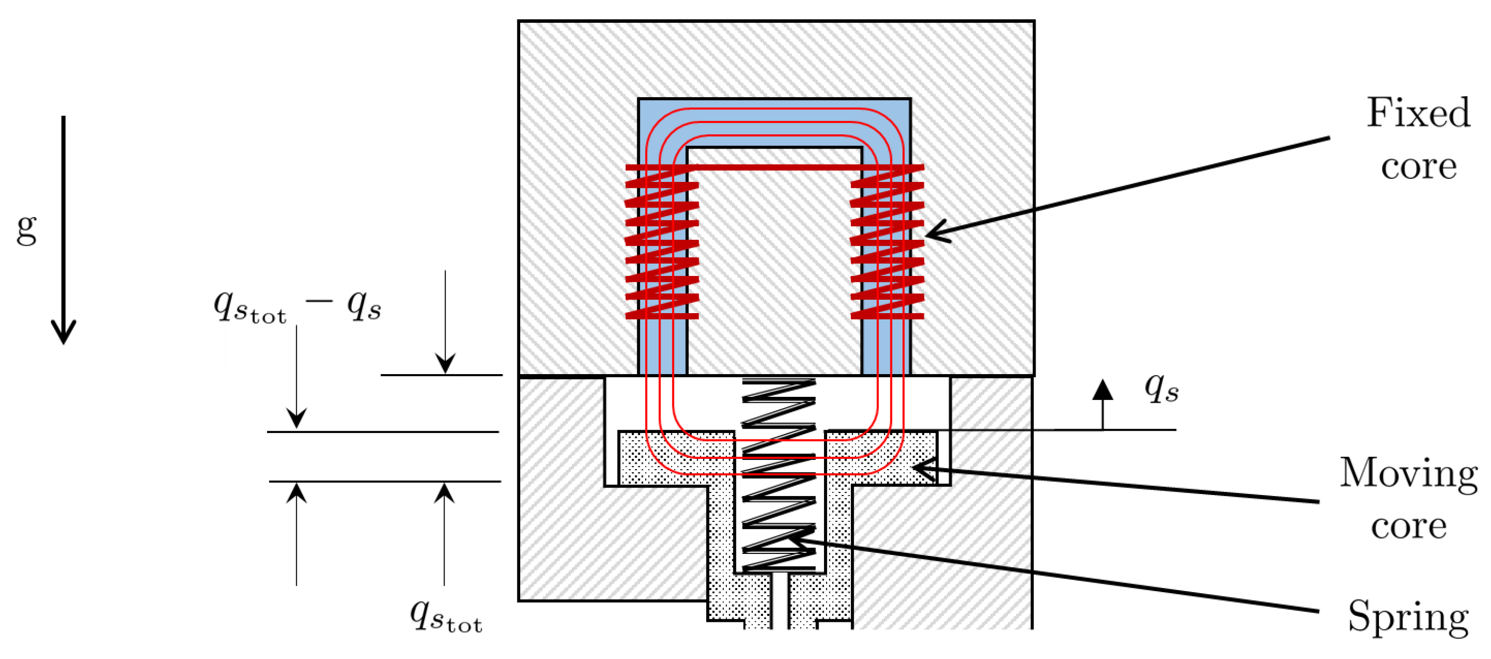
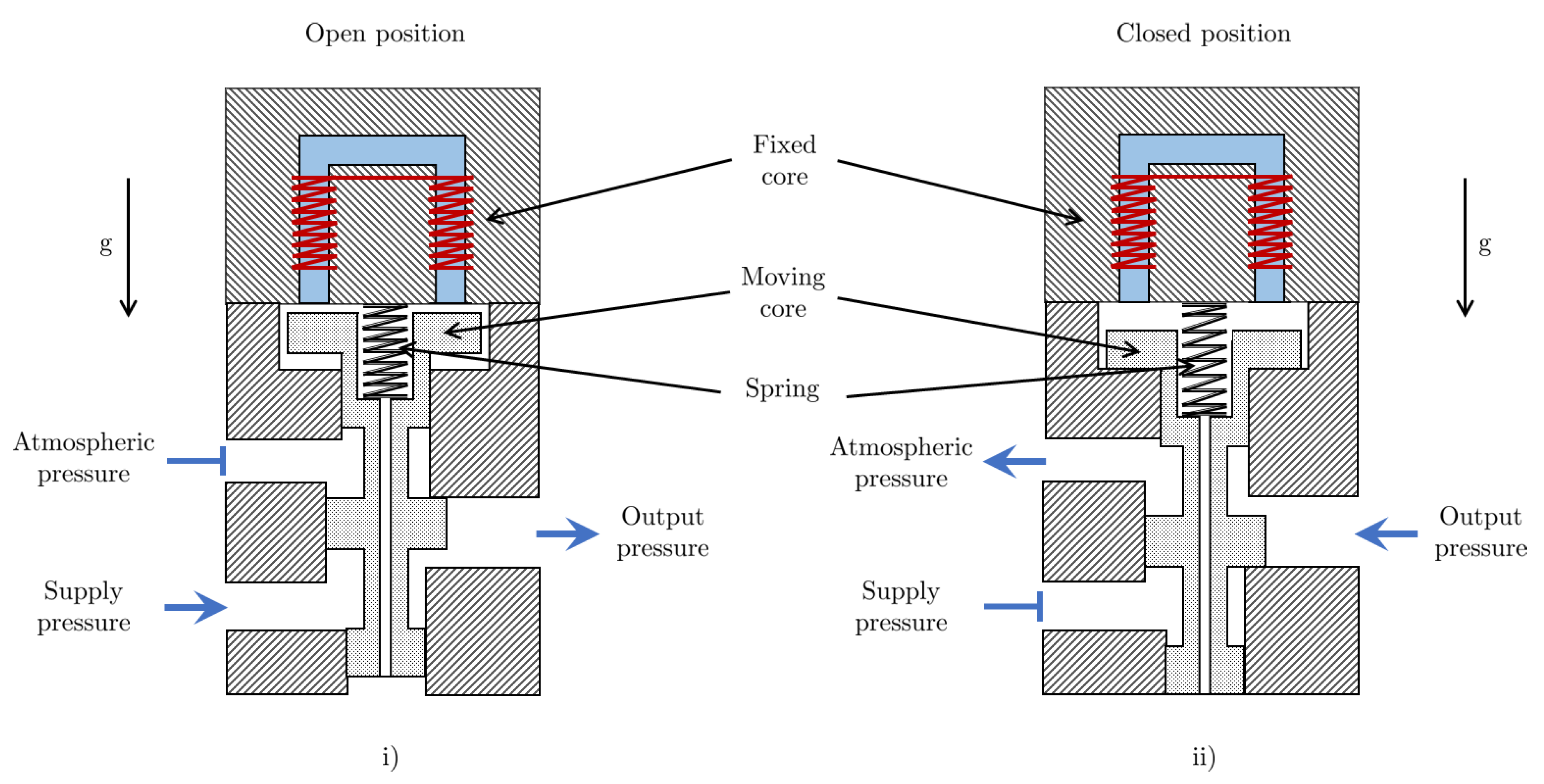
Figure 3 shows a solenoid valve in the open and closed position. It is assumed that the air gaps are sufficiently small such that the effect of fringing of the magnetic flux is negligible. Consider a solenoid in which the permeability of the core and the length of the part of the magnetic circuit inside the core are denoted by μ c R + 1 and l c R + 1 , respectively. The equivalent length of the solenoid’s magnetic circuit, l e q · : R R is dependent on the displacement of the spool, q s R , and can be written as
l e q q s = l c + μ c μ 0 ( q s tot q s )
where μ 0 R + 1 are the permeability of air and q s tot R + 1 is the total air-gap. The solenoid coordinate systems is represented in Figure 4.
Figure 4. Solenoid coordinate system
Preprints 107578 g003
Figure 3. Diagram of a Solenoid valve in the i) open position which allows fluid flow and ii) closed position which stops fluid flow
Preprints 107578 g004
Thus, the inductance of the solenoid varies with displacement of the spool and hence can be expressed by the function L s · : R R given by
L s q s = N 2 A e μ c l e q q s
where N R + 1 is the number of turns in the coil of the solenoid and A e R + 1 is the effective cross-sectional area of the path of the magnetic flux. The magnetic and mechanical subsystems in the solenoid valve are therefore coupled magnetically due to the dependence of the inductance on the displacement of the spool.
The total energy of the solenoid is given by the Hamiltonian, H s · : R 3 R , which is a function of the state vector X s = ϕ s , p s , q s R 3 , expressed as the sum of the magnetic, kinetic and potential energies denoted by H magnetic ϕ s , q s : R 2 R , H kinetic p s : R R and H potential q s : R R , respectively. Thus
H s X s = H magnetic ϕ s , q s + H kinetic p s + H potential q s
given a magnetic flux ϕ s R .
Assuming that the pretension of the spring is set to q 0 R , the Hamiltonian is
H s X s = 1 2 ϕ s 2 L [ q s ] + p s 2 m s + k s ( q s + q s 0 ) 2 + m s q s g
where p s R is the momentum of the spool, m s R + 1 is the mass of the spool, k s R + 1 is the spring stiffness and g R + 1 is the acceleration due to gravity.
Hence, the solenoid’s state and output dynamics are expressed in Port-Hamiltonian form in equations 13 and respectively
X ˙ s = J s R s H s X s + G s u s
Y s = G s * u s
where
J s = 0 0 0 0 0 1 0 1 0 , R s = R s 0 0 0 b s 0 0 0 0 , G s = 1 0 0 0 0 0 ( A s 1 A s 2 ) ( A s 3 A s 4 ) , G s * = G s , u s = V s p s and H s X s = ϕ s A e N 2 μ c l c μ c ( q s q s tot ) μ 0 p s m s A e N 2 μ c 2 μ 0 μ 0 l c μ c ( q s q s tot ) 2 + k s ( q s + q s 0 ) + m s g
where R s R + 1 is the resistance of the coil, b s R + 1 is the viscous damping acting on the spool and is the gradient operator. A s 1 , A s 2 R + 1 are the various cross-sectional areas of the lands of the spool and the input vector u s R 2 consists of the input voltage V s R 1 and the supply pressure p s R 1 . It can be seen that J s = J s R 3 × 3 possesses skew-symmetry, while R s = R s R 3 × 3 is positive semi-definite.
Taking the time derivative of the Hamiltonian
H ˙ s [ χ s ] = u s · Y s H s [ X s ] · ( R s H s [ X s ] )
This system has power and resistive ports.

5.1. Pipe Model

In this section, a port-Hamiltonian model of a single pipe segment is developed. The basis of these developments is the Navier Stokes equations for one-dimensional non-stationary flow of gas in a pipe. The following assumptions are taken for the sake of model simplification [14,15]:
  • The pipe is taken as rigid (it does not expand in cross-section as a result of fluid flow).
  • Frictional and gravitational effects are neglected (this will be relaxed in future works in this research area),
  • The model parameters of the gas remain constant along the pipe cross-section but vary in time along the pipe length. Thus they can be averaged about the cross-section and thus the gas flow is one-dimensional.
  • The temperatures of the pipe walls are assumed to be constant and equal to the ambient room temperature. Hence temperature effects are ignored.
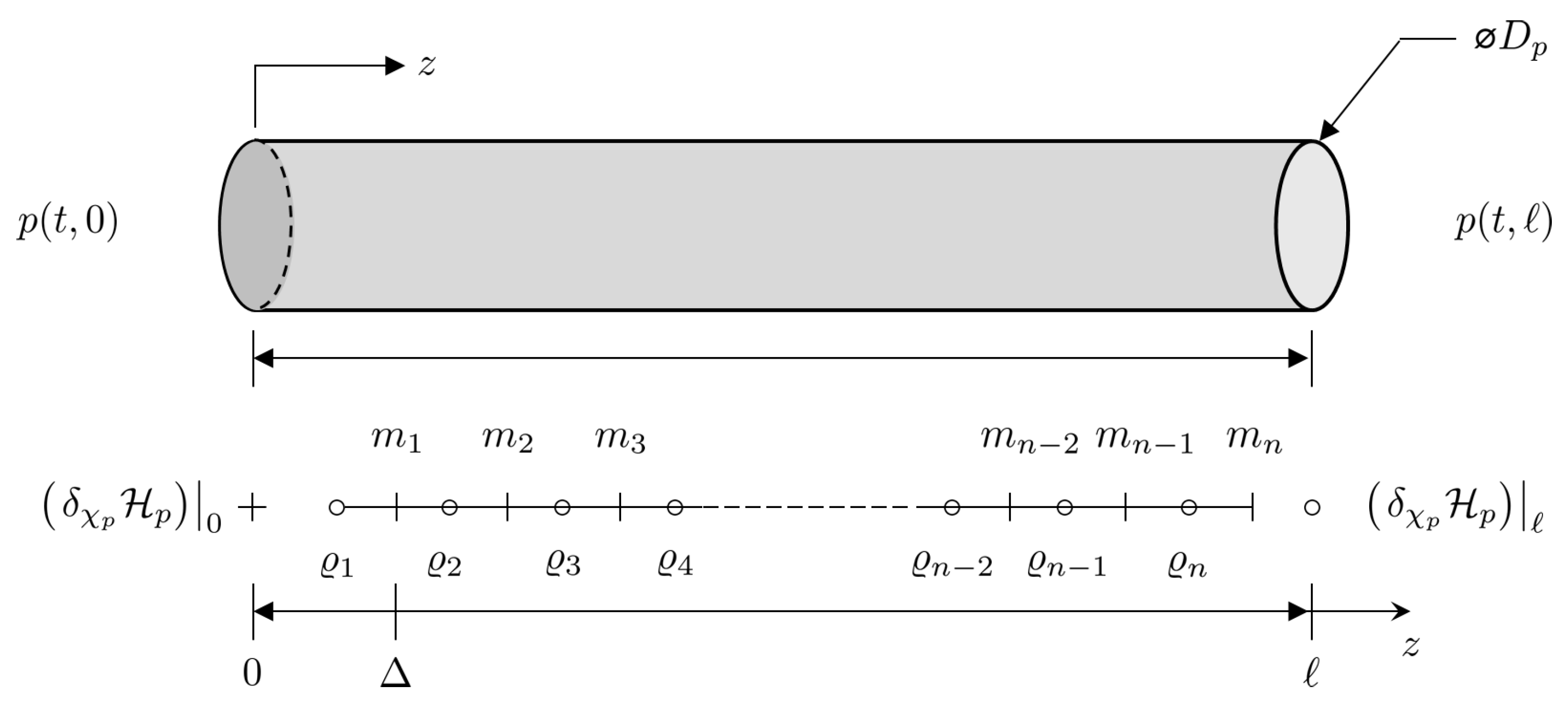
Taking into account these assumptions, the coordinate system attached to a segment of pipe is illustrated in Figure 5.
Thus, for a given time interval t s t < t f with start time t s and finish time t f , the length normalized one-dimensional Euler equations for gas of density ρ ( t , z ) : ( t s , t f ] × ( 0 , ) R 1 flowing at a velocity ν ( t , z ) : ( t s , t f ] × ( 0 , ) R 1 through a pipe of length R + 1 and cross-sectional area A p R + 1 are given by:
t ( ρ A p ) + z ( ρ A p ν ) = 0
t ( ρ A p ν ) + z ( ρ A p ν 2 + p A p ) = 0
where p ( t , z ) : ( t s , t f ] × ( 0 , ) R 1 is the pressure and i / i is the partial derivative with respect to the temporal and spatial variables given by the subscripts i t , z .

5.1.1. Port-Hamiltonian Formulation of Pipe-Flow Model

The fluid dynamics can be written in terms of mass per unit length, i.e. ϱ ρ A p , as well as the fluid momentum, m ϱ ν . Thus equations 16a and can be expressed as
t ϱ = z m
t m = z m 2 ϱ + p A p
Defining the state vector of the gas flow through a pipe segment as χ p ϱ m , the energy of the gas can be expressed in form of a Hamiltonian H p χ p : R 2 R 1 given by
H p χ p = 0 H p χ p d x = 0 m 2 2 ϱ + ϱ U ϱ / A p d x
where H p · : R 2 R 1 is the Hamiltonian density and U · : R 1 R 1 is the internal energy of the gas which in the case of an isentropic fluid, can be expressed as a function of density.
The port-Hamiltonian dynamics take the following form
t χ p = J χ p δ χ p H p χ p
where J χ p , the formally skew-symmetric operator and δ χ p H χ p , the variational derivative of the Hamiltonian density are expressed as
J χ p = 0 z z 0 and δ χ p H p χ p = h m 2 2 ϱ 2 m ϱ
where h is the enthalpy, and J χ p is a formally skew-symmetric operator.
The rate of change of the Hamiltonian can be found as
H ˙ p = u p y p
where
u p = W B R ext δ χ p H p 0 δ χ p H p and y p = W C R ext δ χ p H p 0 δ χ p H p
with components given by
W B = 1 2 1 0 0 1 0 1 1 0 , W C = 1 2 0 1 1 0 1 0 0 1 , R ext = 1 2 0 1 0 1 1 0 1 0 1 0 1 0 0 1 0 1
and δ χ p H p 0 δ χ p H p = h m 2 2 ϱ 2 0 m ϱ 0 h m 2 2 ϱ 2 m ϱ
Expanding u p and y p
u p = m ϱ h m 2 2 ϱ 2 0 and y p = h m 2 2 ϱ 2 m ϱ 0
Thus, the rate of change of the Hamiltonian is
H ˙ p = h m 2 2 ϱ 2 m ϱ m ϱ 0 h m 2 2 ϱ 2 0

5.2. Electric Circuit Model of the Lung

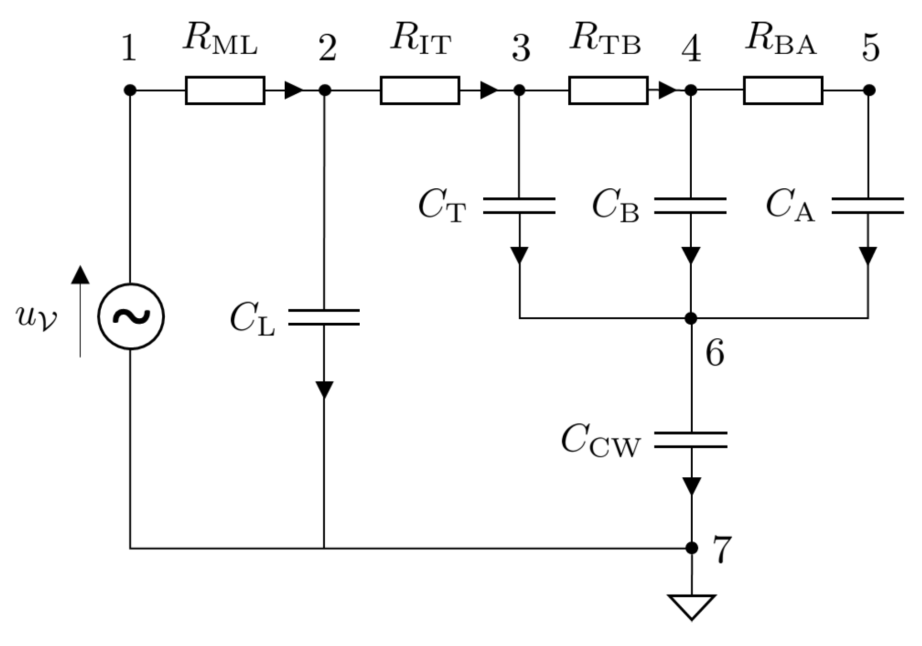
The port Hamiltonian formulation for nonlinear electric circuits is presented in this section. Since the main focus of this article is on the mechanical ventilator model, the lung model is simplified by considering an electric circuit analogy. The model under consideration is that of a fully sedated patient who relies completely on the mechanical ventilator to breathe. The circuit model is shown in Figure 6.
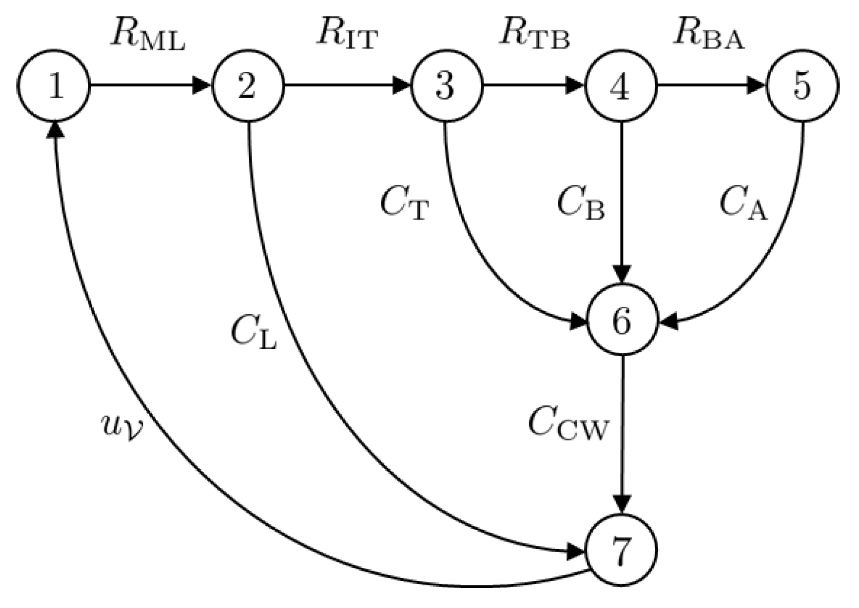
The circuit can be represented in the form of a network graph using graph theory. The graph of the circuit given in Figure 6 is given in Figure 7. The model has n = | V | = 7 vertices.
The complete graph of the circuit, A 0 , is
Preprints 107578 i001
The ventilator input voltage is represented as a source S = ( D S , L S , R S ) . The set of sources is S = v 7 and the dimension | S | = 1 source. The circuit also consists of m C = 5 capacitors (storage elements) that are represented as C i = ( D C i , L C i , R C i ) where the i th index is used to distinguish between the components is i = C L , C T , C B , C A , C CW . Furthermore there are m R = 4 resistors (dissipative elements) that are represented as R i = ( D R i , L R i , R R i ) where the i th index is given by i = R ML , R IT , R TB , R BA .
Selecting node 7 as the ground, the reduced incidence matrix, A , is given by
Preprints 107578 i002
where the dimensions of the components of A are dim ( A R ) = ( n | S | ) × m R = 6 × 4 , dim ( A C ) = ( n | S | ) × m C = 6 × 5 and dim ( A S ) = ( n | S | ) × m S = 6 × 1 .
The total energy of the circuit is given by the Hamiltonian
H C = i H C i ( q C i ) = 1 2 i q C i C i
where q C i R 1 is the charge of the i th capacitor for i = C L , C T , C B , C A , C CW
I A C A R A S O O O O O O O O O O O O d d t q d d t q C i R i S + O O O O A R O I O A C I O O A S O O I ϕ u C u R u S = O
where I and O are appropriately sized identity and zero matrices, respectively and q = 0 and ϕ is the node potential. Expanding Equation 41
A C d d t q C + A R ( A R ϕ ) + A S i S = 0
A C ϕ + u C = 0
A S ϕ + u S = 0
The Dirac structure is given by the set where D , L , R
d d t q , d d t q C , i R , i S , ϕ , u C , u R , u S D
q , q C , ϕ , u C L
i R , e R R

6. Model Network Topology

Definition 1.(Directed graph) [17] A directed graph, G denotes the pair ( V , A ) , where V ( D ) and A ( D ) denote the set of vertices and arcs respectively. An arc is a distinct ordered pair of vertices.
The directed graph of a mechanical ventilator model is composed of the disjoint union of the vertices associated with the patient, as well as the inspiratory and expiratory limbs of the ventilator given by v O , V I and V E respectively. Similarly, the patient, inspiratory and expiratory arcs given by a O , A I and A E , respectively. Each arc and vertex can further be subdivided into those associated with blowers, valves, pipes and electric circuits present in the mechanical ventilator. Thus the totality of vertices and arcs are given by
V ( D ) = v O V I V E = v O ( V I b V I v V I p V I e ) ( V E b V E v V E p V E e )
and
A ( D ) = a O A I A E = a O ( A I b A I v A I p A I e ) ( A E b A E v A E p A E e )
respectively, where the subscripts i O , p , b , v , p , e are used to indicate the patient, blowers, valves, pipes and electric circuits components, respectively.
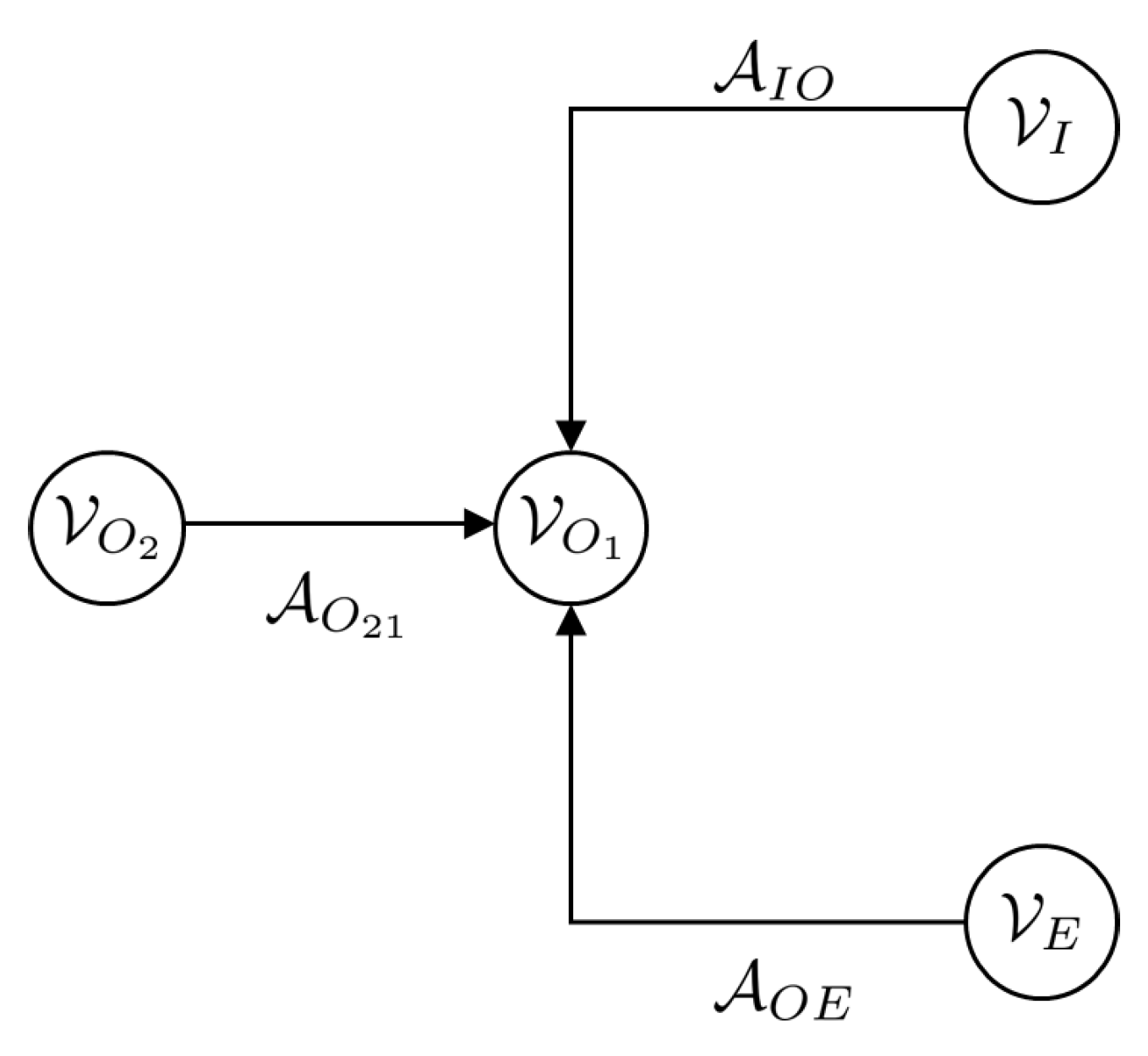
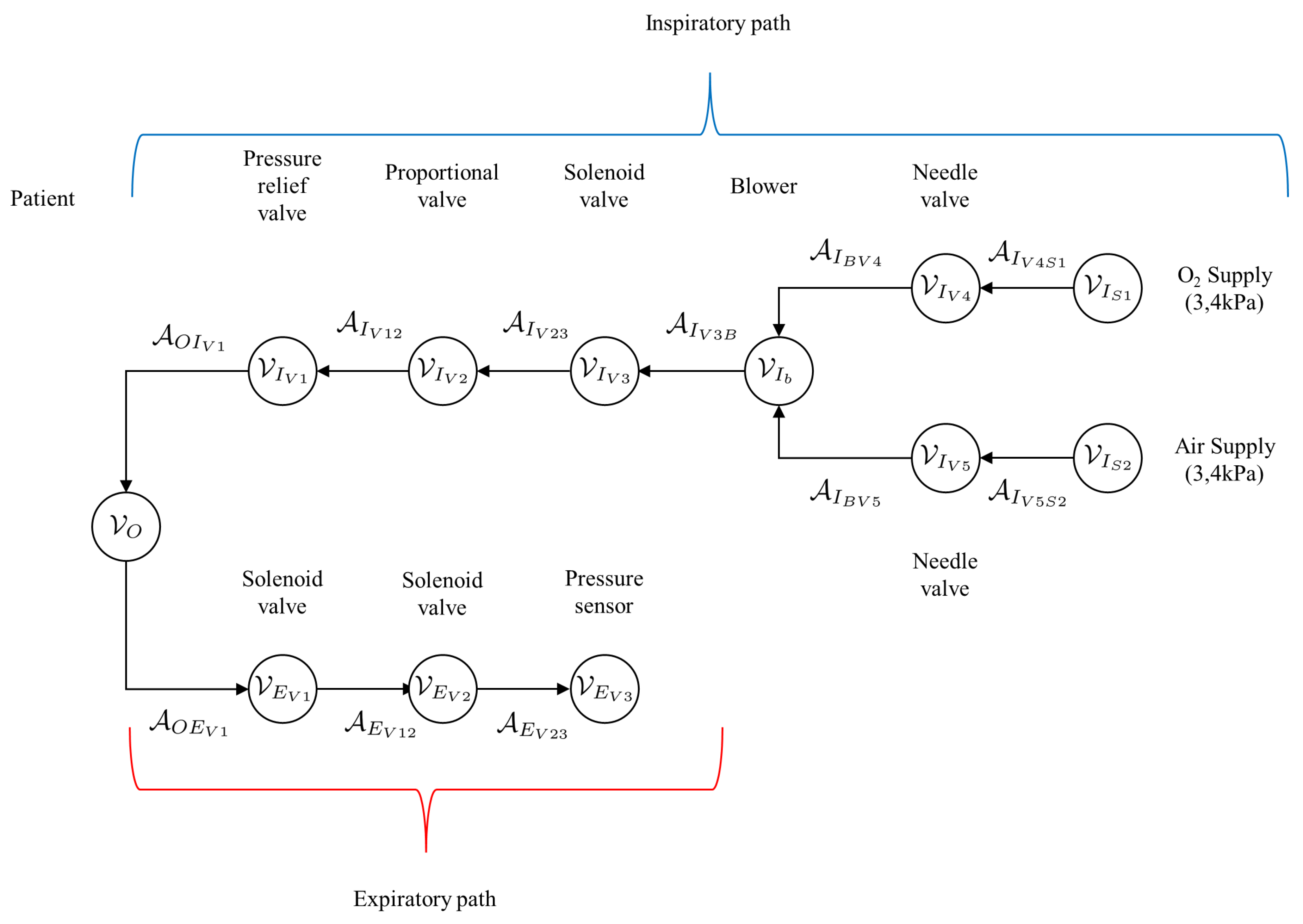
Figure 9 shows a detailed graph of the mechanical ventilator given in Figure 2 indicating the patient vertex V O , the arcs and vertices along the inspiratory path given by
A I A I V 12 , A I V 23 , A I V 3 B , A I V 23 , A I B V 4 , A I V 4 S 1 , A I B V 5 , A I V 5 S 2
and
V I V I V 1 , V I V 2 , V I V 3 , V I B , V I V 4 , V I S 1 , V I V 5 , V I S 2
respectively, as well as the arcs and vertices along the expiratory path given by
A E A O E V 1 , A E V 12 , A E V 23 and V E V E V 1 , V E V 2 , V E V 3
respectively.
Figure 8. Simplified graph of the mechanical ventilator given in Figure 2 indicating the elements belonging to the patient, given by the arcs A O 21 A O and vertices V O 1 , V O 2 V O as well as elements of the inspiratory and expiratory arcs and vertices given by and V I , V E and A I O , A O E , respectively.
Preprints 107578 g008
Figure 9. Detailed graph of the Mechanical Ventilator given in Figure 8 indicating the patient vertex V O , as well as the arcs and vertices along the inspiratory and expiratory paths.
Preprints 107578 g009

7. Model Interconnection/Coupling Conditions

In this section, the coupling conditions of the port-Hamiltonian network model of the mechanical ventilator are given. The types of interconnections occurring in this model are given below:
  • Pump-to-pipe interconnection The pressure and flow rate of the fluid exiting the pump, P b and Q b respectively, are equal to the pressure and flow rate at the inlet of the pipe given by p ( 0 ) and m ( 0 ) , respectively. Thus
    P b = p 0 and Q b = m ( 0 )
  • Pipe to valve interconnection The pressure and flow rate of the fluid entering/exiting a valve, P v and Q v respectively, are equal to the pressure and flow rate at the inlet/outlet of the pipe given by p ( 0 ) and m ( 0 ) for the inlet and p ( ) and m ( ) . Thus
    P v = p ( 0 ) and Q v = m ( 0 ) at the inlet P v = p ( ) and Q v = m ( ) at the outlet
  • Pipe to circuit interconnection The pressure and fluid flow-rate at the outlet of a pipe can act as inputs to a circuit model, thus
    p ( ) = v c in and m ( ) = i c in
    On the other hand, the output voltage and current of a circuit can be interconnected to a fluid pipe at the inlet of the pipe. In this case, the output voltage and or current of the circuit should be equal to the inlet pressure and inlet flow rate respectively. This relation can expressed mathematically as:
    v c o u t = p ( 0 ) and i c o u t = m ( 0 ) at the inlet
    The Hamiltonian of the complete system is given by the sum of the Hamiltonian’s of the individual systems
    H = H b + H s + H p + H C
    The rate of change of energy of the complete system is
    H ˙ = P ˙ b ( z p ( 0 ) + F p ) + Q ˙ b ( z m ( 0 ) + M p ) + P ˙ v i n ( z p ( 0 ) + F v i n ) + Q ˙ v i n ( z m ( 0 ) + M v i n ) + P ˙ v o u t ( z p ( ) + F v o u t ) + Q ˙ v o u t ( z m ( ) + M v o u t ) + P ˙ v o u t ( z p ( ) + F v o u t ) + Q ˙ v o u t ( z m ( ) + M v o u t ) + H ˙ b + H ˙ s + H ˙ c
    The terms F p , M p , F v i n , M v i n , F v o u t and M v o u t are the external pressure and flow rates acting on the system. They should be equal to zero to complete the interconnection.

8. Structure Preserving Discretization

The port Hamiltonian model of the pipe is a partial differential equation, continuous in space. As such it is difficult to simulate the dynamics of a pipe section. In order to do this, it is necessary to approximate the model with a discrete model, in this case, a finite difference model which is an approximation of the original system. Within the context of port Hamiltonian systems, an additional requirement is the need to ensure that the discrete approximation maintains the structural properties of the original system e.g. skew symmetry etc.
Each system state can be replaced with a discrete approximation consisting of a total on n elements as can be seen in Figure 10. As such, ϱ ϱ d = ϱ 1 , ϱ 2 , , ϱ n R n × 1 and m m d = m 1 , m 2 , , m n R n × 1 . As such, state vector χ p can be replaced by a discrete approximation χ d = ϱ 1 , , ϱ n , m 1 , , m n R 2 n × 1 . The i th element of ϱ i , m i R 1 × 1 is located at z = Δ ( i 1 ) , Δ ( i 1 / 2 ) , where Δ is the fixed discrete step size between points and i = 1 , 2 , , n . In addition, the efforts at the boundaries are given by δ χ 0 H 0 and δ χ n H n . Thus the Hamiltonian given in Equation 18 can be approximated by a discrete approximation such that H p [ χ p ] Δ H d [ χ d ] so that the discrete system effort is now δ χ d ( H d ) . A finite difference approximation of the spatial derivatives at the i th point is
z ϱ ( t , z ) i 1 Δ ( ϱ ( t , z i + 0.5 ) ϱ ( t , z i 0.5 ) ) and z m ( t , z ) i 1 Δ ( m ( t , z i + 1 ) m ( t , z i ) )
The central difference approximation at the i th point is
t ϱ i m i = 1 Δ δ m H [ χ i ] δ ϱ H [ χ i + 1 ] δ m H [ χ i 1 ] δ ϱ H [ χ i ]
In matrix form this is
t ϱ d = 1 Δ 1 1 1 1 1 δ m H [ χ d ] + 1 Δ 1 0 0 δ m H [ χ d ]
t m d = 1 Δ 1 1 1 1 1 δ ϱ H [ χ d ] + 1 Δ 0 0 1 δ ϱ H [ χ 0 ]
which can be re-written as
t ϱ d = D δ m H [ χ d ] + G ϱ δ m H [ χ 0 ]
t m d = D δ ϱ H [ χ d ] + G m δ ϱ H [ χ n ]
where
D = 1 Δ 1 1 1 1 1 , G ϱ = 1 Δ 1 0 0 and G m = 1 Δ 0 0 1
The skew-symmetric operator is clear from Equation Section 8.
t ϱ d t m d = D D δ ϱ H [ χ d ] δ m H [ χ d ] + G m G ϱ δ ϱ H [ χ 0 ] δ m H [ χ n ]
Figure 10. Staggered grid discretization of the one dimensional port Hamiltonian pipe dynamic model
Preprints 107578 g010

9. Results and Discussion

The pipe and solenoid valve model parameters used in this work are given in Table 1 and Table 2, respectively.

9.1. Model Validation

The model was validated using parameters obtained from the literature. The simulated results provided in the results and discussion section were found to be comparable to those in the existing literature.

9.2. Simulation Environment

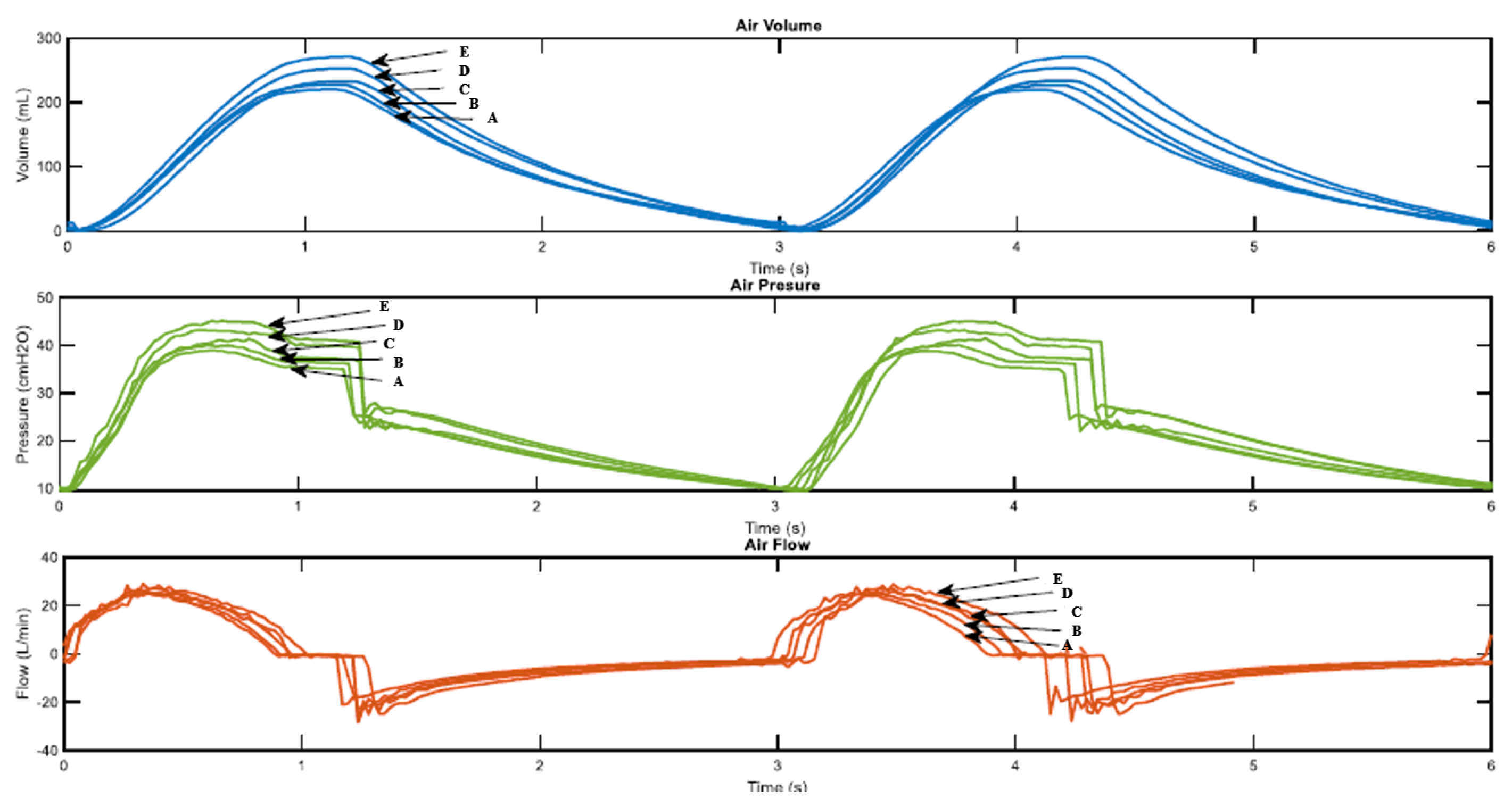
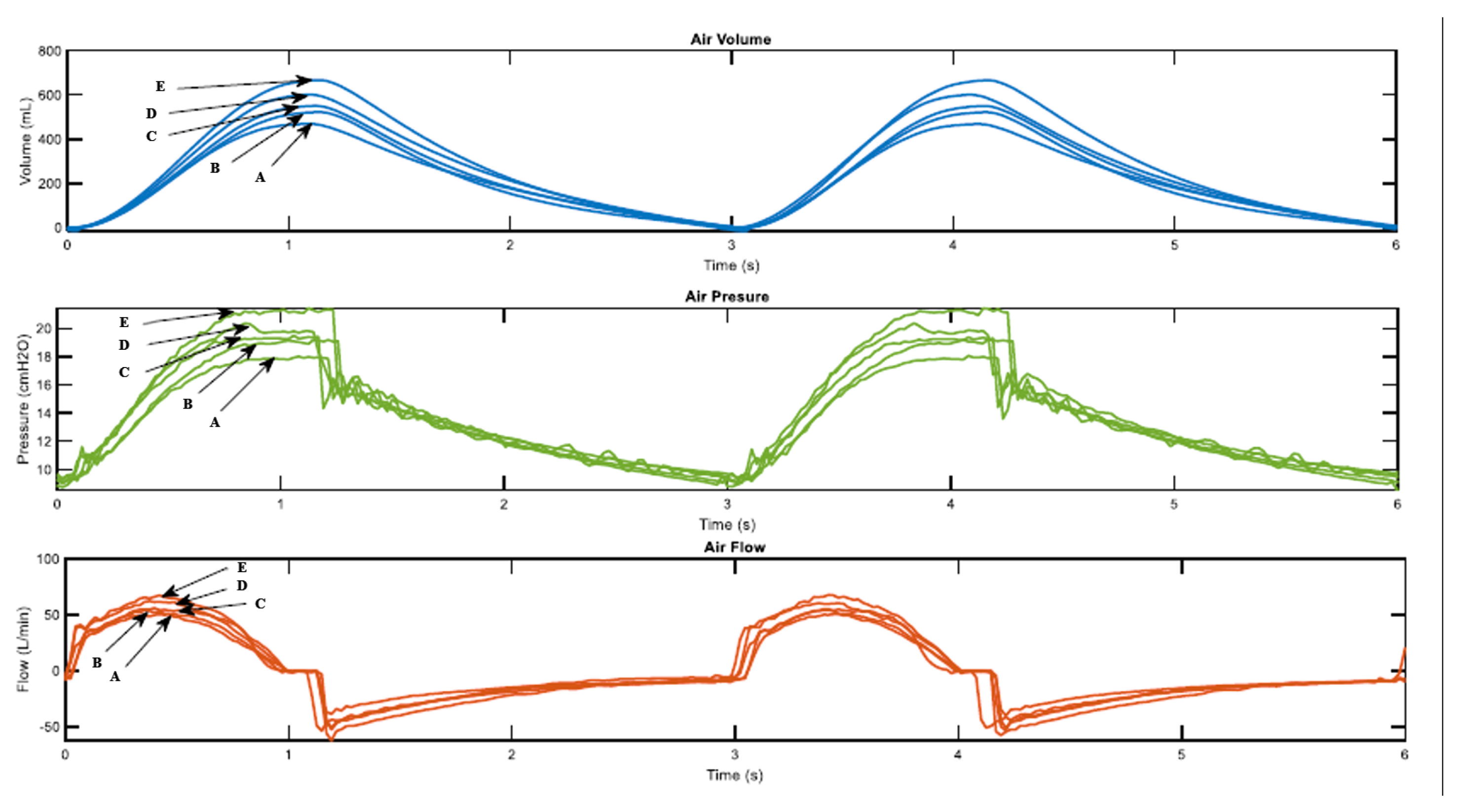
Simulations were conducted using MATLAB. Three conditions were used to simulate the mechanical ventilator behaviour with the following lung conditions: compliance 50 mL/cmH2O and resistance 5cmH2O-s/L, compliance 20 mL/cmH2O and resistance 20cmH2O-s/L and compliance 10 mL/cmH2O and resistance 50cmH2O-s/L. For each condition, all the sizes were tested for 2 min per size and the ventilation curves air volume, The conditions were chosen in order to have a fair comparison with results that exist in literature that used similar lung compliance. pressure and flow over time were obtained. The simulation results are shown in Figure 6.10 and 6.11, where A, B, C, D, and E represent various cams sizes of the mechanical ventilator from extra small (A), small(B), Medium(C), Large (D) and extra-large(E)
Figure 11. Air pressure, volume and flow versus time graph
Preprints 107578 g011
Figure 12. Mechanical Ventilator Simulation results
Preprints 107578 g012
The figure show ventilation curves for a lung under two conditions, for a partially damaged lung whose compliance and resistance of 20 mL/cmH2O and 20cmH2O-s/L respectively. The lung with complete damage is represented by lung compliance and resistance of 10 mL/cmH2O and resistance 50cmH2O-s/L. As the cam size increases the ventilation curves maintain the same sinusoidal behavior. For a damaged lung case study, minimum ventilation values of flow over time and air volume are achieved. In a damaged lung, the compliance and resistance of the lung increases the pressure.

10. Conclusions and Recommendations

In these research work, the formulation of a detailed mechanical ventilator in the port Hamiltonian framework. This is followed by a Port Hamiltonian model of the respiratory system and thereafter, these two systems integrated. The work conducted demonstrates the the Port Hamiltonian approach is a valid method in the modelling of integrated Mechanical ventilator human respiratory system.

Author Contributions

For research articles with several authors, a short paragraph specifying their individual contributions must be provided. The following statements should be used “Conceptualization, Milka madahana. methodology, Milka. Madahana; software, Milka.Madahana.; validation, Milka.Madahana and John.Ekoru.; formal analysis, Milka.Madahana.; investigation, Milka.Madahana.; resources, Milka.Madahana.; data curation, Milka.Madahana.; writing—original draft preparation, Milka.Madahana.; writing—review and editing,Milka Madahana; visualization, Milka.Madahana.; supervision, Otis.Nyandoro.; project administration, Milka.Madahana.; funding acquisition, Milka Madahana. All authors have read and agreed to the published version of the manuscript.”, please turn to the CRediT taxonomy for the term explanation. Authorship must be limited to those who have contributed substantially to the work reported.

Funding

`This research received no external funding’.

Institutional Review Board Statement

“Ethical review and approval were waived for this study because the study does not involve humans or animals.

Data Availability Statement

Not applicable

Acknowledgments

I would like to acknowledge the School of Mining, the Faculty of Engineering, and the Built Environment, University of the Witwatersrand for the financial support to publish this work.

Conflicts of Interest

“The authors declare no conflict of interest.” .

Abbreviations

The following abbreviations are used in this manuscript:
MDPI Multidisciplinary Digital Publishing Institute
DOAJ Directory of open access journals
TLA Three letter acronym
LD Linear dichroism

References

  1. Rubio, J.; Rojas, C.; Sanchez, M.; Gómez-Alzate, D.; Córdova, M.; Montoya, V.; Castaneda, B.; Chang, J.; Pérez-Buitrago, S. COVOX: Providing oxygen during the COVID-19 health emergency. HardwareX 2023, 13, e00383. [Google Scholar] [CrossRef] [PubMed]
  2. Tran, A.; Ngo, H.Q.T.; Dong, K.; Huy, V. Design, Control, Modeling, and Simulation of Mechanical Ventilator for Respiratory Support. Mathematical Problems in Engineering 2021, 2021, 1–15. [Google Scholar] [CrossRef]
  3. El-Hadj, A.; Kezrane, M.; Ahmad, H.; Ameur, H.; Bin Abd Rahim, S.Z.; Younsi, A.; Abu-Zinadah, H. Design and simulation of mechanical ventilators. Chaos, Solitons & Fractals 2021, 150, 111169. [Google Scholar] [CrossRef] [PubMed]
  4. Tharion, J.; Kapil, S.; Muthu, N.; Tharion, J.; Subramani, K. Rapid Manufacturable Ventilator for Respiratory Emergencies of COVID-19 Disease. Transactions of the Indian National Academy of Engineering 2020, 5. [Google Scholar] [CrossRef] [PubMed]
  5. Pivik, W.J.; Clayton, G.M.; Jones, G.F.; Nataraj, C. Dynamic Modeling of a Low-cost Mechanical Ventilator. IFAC-PapersOnLine 2022, 55, 81–85. [Google Scholar] [CrossRef]
  6. Al Naggar, N. Modelling and Simulation of Pressure Controlled Mechanical Ventilation System. Journal of Biomedical Science and Engineering 2015, 8, 707–716. [Google Scholar] [CrossRef]
  7. Shi, Y.; Ren, S.; Cai, M.; Xu, W. Modelling and Simulation of Volume Controlled Mechanical Ventilation System. Mathematical Problems in Engineering 2014, 2014. [Google Scholar] [CrossRef]
  8. Al Naggar, N.; Al-Hetari, H.; Alakwaa, F. Simulation of Mathematical Model for Lung and Mechanical Ventilation. Journal of Science and Technology 2016, 21, 1–11. [Google Scholar] [CrossRef]
  9. Giri, J.; Kshirsagar, N.; Wanjari, A. Design and simulation of AI-based low-cost mechanical ventilator: An approach. Materials Today: Proceedings 2021, 47, 5886–5891, SI: TIME-2021. [Google Scholar] [CrossRef] [PubMed]
  10. Hannon, D.; Mistry, S.; Das, A.; Saffaran, S.; Laffey, J.; Brook, B.; Hardman, J.; Bates, D. Modeling Mechanical Ventilation In Silico—Potential and Pitfalls. Seminars in Respiratory and Critical Care Medicine 2022, 43. [Google Scholar] [CrossRef] [PubMed]
  11. Villegas, J.A. A Port-Hamiltonian Approach to Distributed Parameter Systems. PhD thesis, Department of Applied Mathematics, Faculty EWI, Universiteit Twente, Enschede, Twente, Enschede, Netherlands, 2007.
  12. Le Gorrec, Y.; Zwart, H.; Maschke, B. Dirac structures and Boundary Control Systems associated with Skew-Symmetric Differential Operators. SIAM Journal on Control and Optimization 2005, 44, 1864–1892. [Google Scholar] [CrossRef]
  13. van der Schaft, A.J.; Maschke, B.M. Hamiltonian formulation of distributed-parameter systems with boundary energy flow. Journal of Geometry and Physics 2002, 42, 166–194. [Google Scholar] [CrossRef]
  14. Anderson, J. Computational Fluid Dynamics: The Basics with Applications; McGraw-Hill International Editions: Mechanical Engineering, McGraw-Hill, 1995. [Google Scholar]
  15. Kamiński, Z. A simplified lumped parameter model for pneumatic tubes. Mathematical and Computer Modelling of Dynamical Systems 2017, 23, 523–535. [Google Scholar] [CrossRef]
  16. Albanese, A.; Cheng, L.; Ursino, M.; Chbat, N.W. An integrated mathematical model of the human cardiopulmonary system: model development. American journal of physiology. Heart and circulatory physiology 2016, 310 7, H899–921. [Google Scholar] [CrossRef]
  17. Bondy, J.A.; Murty, U.S.R. Graph Theory with Applications; MacMillan, 1976.
  18. Taghizadeh, M.; Ghaffari, A.; Najafi, F. Modeling and identification of a solenoid valve for PWM control applications. Comptes Rendus Mécanique 2009, 337, 131–140. [Google Scholar] [CrossRef]
Figure 1. The energy storage, routing and dissipation
Preprints 107578 g001
Figure 2. Schematic diagram of a Mechanical Ventilator
Preprints 107578 g002
Figure 5. Pipe segment coordinate system
Preprints 107578 g005
Figure 6. Circuit diagram of an electric model of a lung of a fully sedated patient [16]
Preprints 107578 g006
Figure 7. The graph associated with the circuit diagram given in Figure 6
Preprints 107578 g007
Table 1. Pipe model parameters values.
Parameter Description Value Units
A p Pipe cross-sectional area 3.8013 × 10 4 m 2
D p Pipe diameter 2.2 × 10 3 m
Pipe length 1.5 × 10 1 m
Table 2. Solenoid model parameters values [18].
Parameter Description Value Units
A e Effective cross-sectional area 8 × 10 5 m 2
A s 1 Spool land area 2.657 × 10 3 m 2
A s 2 Spool land area 3.525 × 10 3 m 2
A s 3 Spool land area 5.586 × 10 3 m 2
A s 4 Spool land area 5.586 × 10 3 m 2
b s Viscous damping factor 2 × 10 1 N s · m
g Acceleration due to gravity 9.81 m · s 2
k s Spring stiffness 1 × 10 4 N · m 1
l c Length of the part of the magnetic circuit inside the core 1.15 × 10 2 m
m s Mass of the spool 2.7 × 10 1 k g
N Number of turns in the coil 1250 turns
q s tot Total air-gap 3.3 × 10 4 m
q s 0 Pre-tension in the spring 1.1 × 10 3 m
R s Resistance of the coil 13 Ω
μ 0 Permeability of air 4 π × 10 7 N · A 2
μ c Permeability of the magnetic core 4.8 π × 10 5 N · A 2
Table 3. Lung circuit model parameters values [16].
Parameter Description Value Units
R ML Resistance of the Mouth to Larynx 1.021 cmH   2 O · s · l   1
R LT Resistance of the Larynx to Trachea 3.369 × 10 1 cmH   2 O · s · l   1
R TB Resistance of the Trachea to Bronchi 3.063 × 10 1 cmH   2 O · s · l   1
R BA Resistance of the Bronchi to Alveoli 8.17 × 10 2 cmH   2 O · s · l   1
C L Compliance of the Larynx 1.27 × 10 3 l/cmH   2 O
C T Compliance of the Trachea 2.38 × 10 3 l/cmH   2 O
C B Compliance of the Bronchi 1.31 × 10 2 l/cmH   2 O
C A Compliance of the Alveoli 2 × 10 1 l/cmH   2 O
C CW Compliance of the Chest wall 2.445 × 10 1 l/cmH   2 O
Disclaimer/Publisher’s Note: The statements, opinions and data contained in all publications are solely those of the individual author(s) and contributor(s) and not of MDPI and/or the editor(s). MDPI and/or the editor(s) disclaim responsibility for any injury to people or property resulting from any ideas, methods, instructions or products referred to in the content.
Copyright: This open access article is published under a Creative Commons CC BY 4.0 license, which permit the free download, distribution, and reuse, provided that the author and preprint are cited in any reuse.
Prerpints.org logo

Preprints.org is a free preprint server supported by MDPI in Basel, Switzerland.

Subscribe

© 2024 MDPI (Basel, Switzerland) unless otherwise stated