Submitted:
29 May 2024
Posted:
30 May 2024
You are already at the latest version
Abstract
Keywords:
1. Introduction
2. Materials and Methods
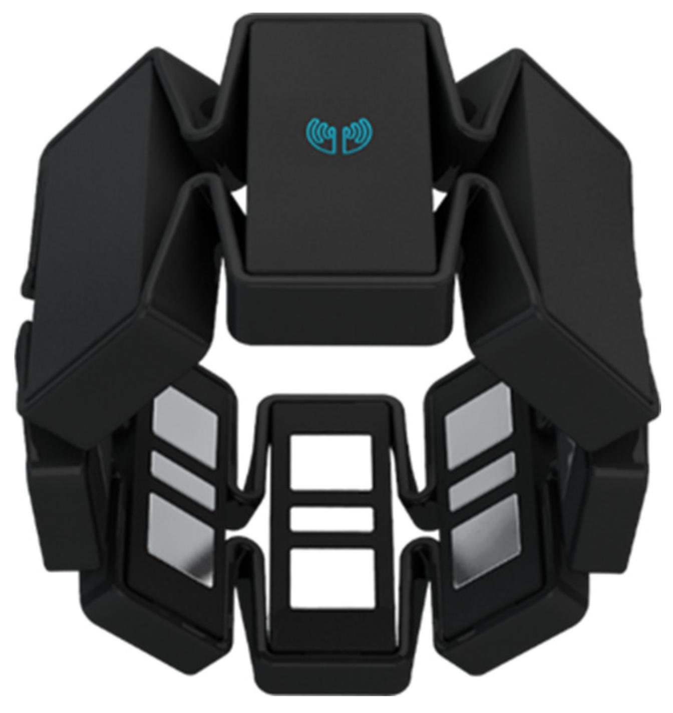
2.1. System Hardware
2.2. Developed Software
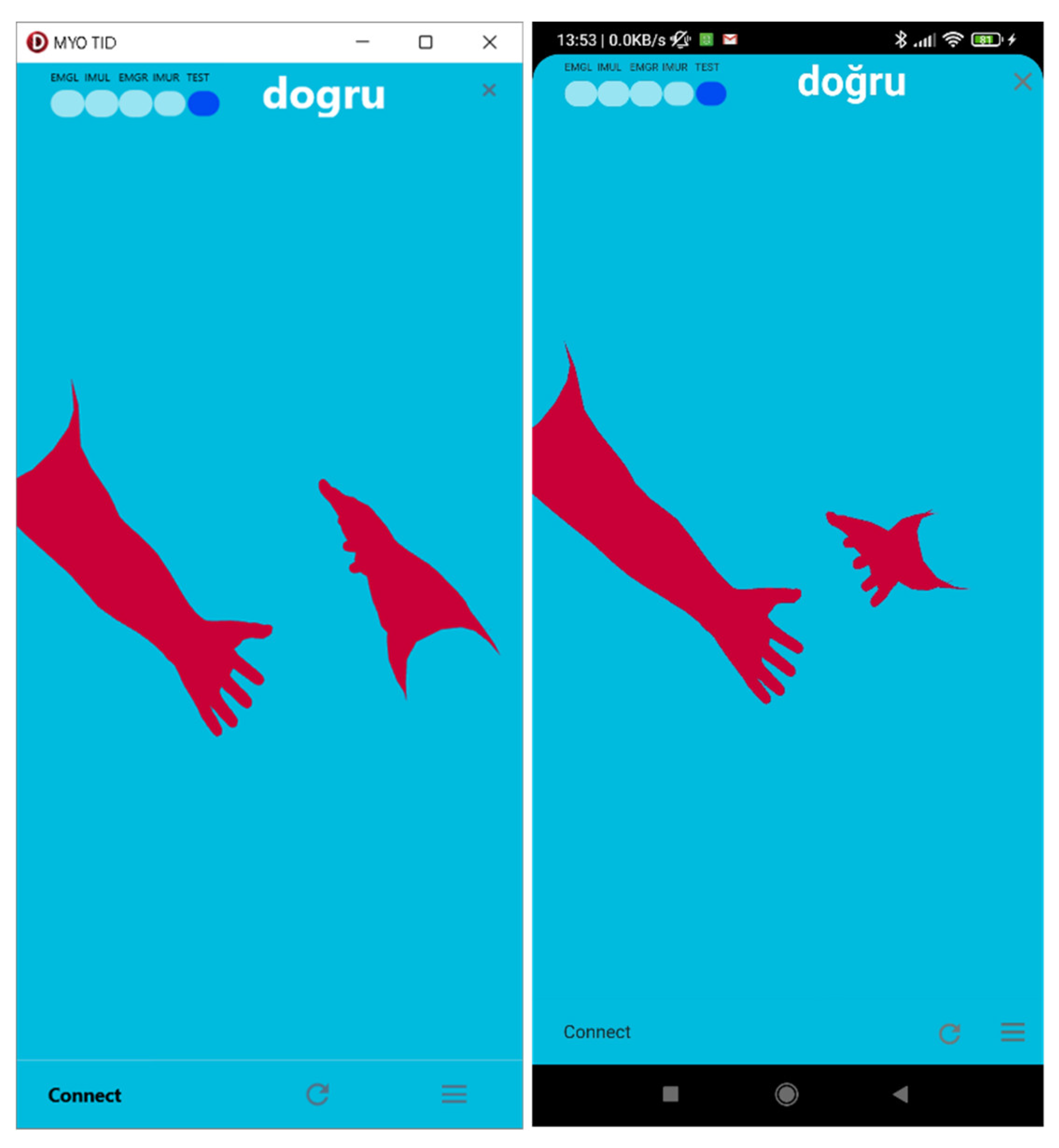
2.2.1. Main User Interface
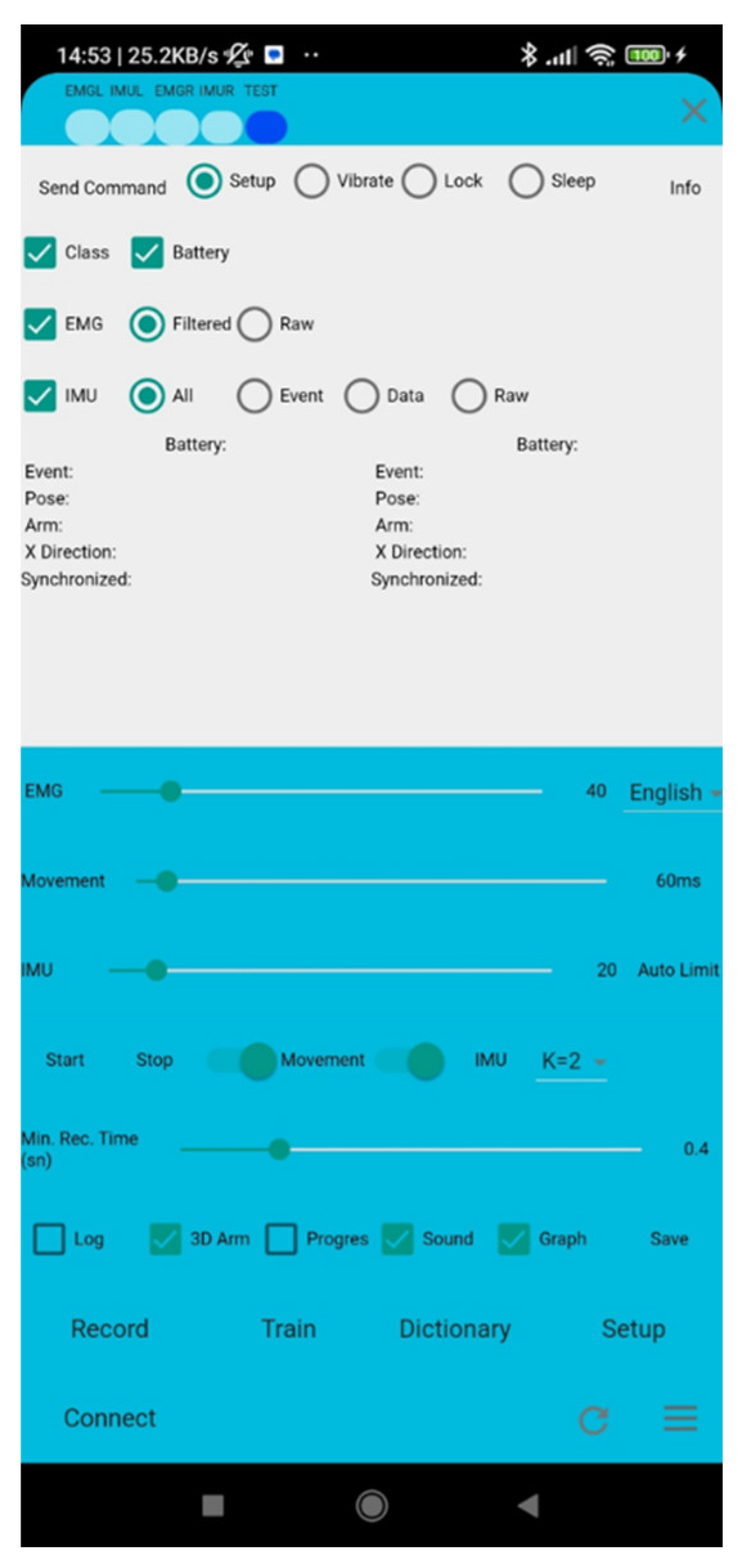
2.2.2. Settings User Interface
2.2.3. Records User Interface
2.2.4. Train User Interface
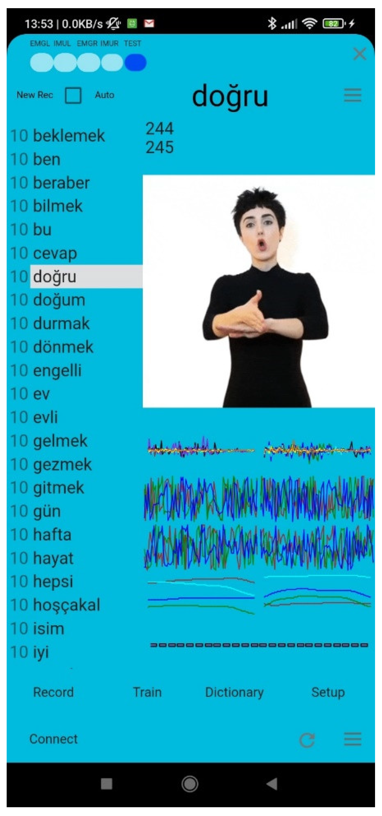
2.2.5. Dictionary User Interface
2.3. Data Collecting
- Greeting and introduction words (hello, I’m glad, meet, etc.), Turkish (merhaba, sevindim, görüşürüz vb.);
- Family Words (mother, father, brother, etc.), Turkish (anne, baba, abi vb.);
- Pronouns and Person Signs (I, you, they etc.), Turkish (ben, sen, onlar vb.);
- Common Verbs (come, go, take, give, etc.), Turkish (gel, git, al, ver, vb.);
- Question Words (what, why), Turkish (ne, neden);
- Other Daily Life Words (home, name, good, warm, easy, married, year, etc.), Turkish (ev, isim, iyi, sıcak, kolay, evli, yıl vb.).
2.4. Feature Extraction
2.5. Classification
3. Results and Discussion
- Real-life usability: The sign language technology should be applicable in real-life situations outside of the laboratory.
- Accuracy and minimal delay: The technology must accurately convert sequences of movements into text and speech with minimal delay.
- Aesthetics and comfort: The design of the technology should prioritize aesthetics and comfort for the user.
- Wireless and rechargeable: To be useful, it must be wireless and easily rechargeable.
- User-centric design: When designing systems.
Author Contributions
Funding
Data Availability Statement
Acknowledgments
Conflicts of Interest
References
- W. H. Organization. “Deafness and hearing loss.” https://www.who.int/news-room/fact-sheets/detail/deafness-and-hearing-loss (accessed 06.04.2023.
- G. E. Crealey and C. O’Neill, “Hearing loss, mental well-being and healthcare use: results from the Health Survey for England (HSE),” Journal of Public Health, vol. 42, no. 1, pp. 77-89, 2018. [CrossRef]
- M. J. Cheok, Z. Omar, and M. H. Jaward, “A review of hand gesture and sign language recognition techniques,” International Journal of Machine Learning and Cybernetics, vol. 10, no. 1, pp. 131-153, 2019/01/01 2019. [CrossRef]
- H.-D. Yang, “Sign Language Recognition with the Kinect Sensor Based on Conditional Random Fields,” Sensors, vol. 15, no. 1, pp. 135-147, 2015. [Online]. Available: https://www.mdpi.com/1424-8220/15/1/135.
- Z. Zafrulla, H. Sahni, A. Bedri, P. Thukral, and T. Starner, “Hand detection in American Sign Language depth data using domain-driven random forest regression,” in 2015 11th IEEE International Conference and Workshops on Automatic Face and Gesture Recognition (FG), 4-8 May 2015, 2015, vol. 1, pp. 1-7. [CrossRef]
- S. B. Abdullahi and K. Chamnongthai, “American Sign Language Words Recognition of Skeletal Videos Using Processed Video Driven Multi-Stacked Deep LSTM,” Sensors, vol. 22, no. 4, p. 1406, 2022. [Online]. Available: https://www.mdpi.com/1424-8220/22/4/1406.
- S. B. Abdullahi and K. Chamnongthai, “American Sign Language Words Recognition Using Spatio-Temporal Prosodic and Angle Features: A Sequential Learning Approach,” IEEE Access, vol. 10, pp. 15911-15923, 2022. [CrossRef]
- S. B. Abdullahi and K. Chamnongthai, “IDF-Sign: Addressing Inconsistent Depth Features for Dynamic Sign Word Recognition,” IEEE Access, vol. 11, pp. 88511-88526, 2023. [CrossRef]
- S. B. Abdullahi, K. Chamnongthai, V. Bolon-Canedo, and B. Cancela, “Spatial–temporal feature-based End-to-end Fourier network for 3D sign language recognition,” Expert Systems with Applications, vol. 248, p. 123258, 2024/08/15/ 2024. [CrossRef]
- Z. Katılmış and C. Karakuzu, “ELM based two-handed dynamic Turkish Sign Language (TSL) word recognition,” Expert Systems with Applications, vol. 182, p. 115213, 2021/11/15/ 2021. [CrossRef]
- C. H. Chuan, E. Regina, and C. Guardino, “American Sign Language Recognition Using Leap Motion Sensor,” in 2014 13th International Conference on Machine Learning and Applications, 3-6 Dec. 2014, 2014, pp. 541-544. [CrossRef]
- H. Wang, M. Leu, and C. Oz, “American Sign Language Recognition Using Multidimensional Hidden Markov Models,” Journal of Information Science and Engineering - JISE, vol. 22, pp. 1109-1123, 09/01 2006.
- N. Tubaiz, T. Shanableh, and K. Assaleh, “Glove-Based Continuous Arabic Sign Language Recognition in User-Dependent Mode,” IEEE Transactions on Human-Machine Systems, vol. 45, no. 4, pp. 526-533, 2015. [CrossRef]
- A. Garg, “Converting American sign language to voice using RBFNN,” Sciences, 2012.
- T. Starner, J. Weaver, and A. Pentland, “Real-time american sign language recognition using desk and wearable computer-based video,” IEEE Transactions on pattern analysis and machine intelligence, vol. 20, no. 12, pp. 1371-1375, 1998. [CrossRef]
- S. D. Thepade, G. Kulkarni, A. Narkhede, P. Kelvekar, and S. Tathe, “Sign language recognition using color means of gradient slope magnitude edge images,” in 2013 International Conference on Intelligent Systems and Signal Processing (ISSP), 2013: IEEE, pp. 216-220. [CrossRef]
- T. Kim, “American Sign Language fingerspelling recognition from video: Methods for unrestricted recognition and signer-independence,” arXiv preprint arXiv:1608.08339, 2016. [CrossRef]
- K. Sadeddine, F. Z. Chelali, and R. Djeradi, “Sign language recognition using PCA, wavelet and neural network,” in 2015 3rd International Conference on Control, Engineering & Information Technology (CEIT), 25-27 May 2015, 2015, pp. 1-6. [CrossRef]
- R. Yang, S. Sarkar, and B. Loeding, “Handling Movement Epenthesis and Hand Segmentation Ambiguities in Continuous Sign Language Recognition Using Nested Dynamic Programming,” IEEE Transactions on Pattern Analysis and Machine Intelligence, vol. 32, no. 3, pp. 462-477, 2010. [CrossRef]
- Y. C. Bilge, R. G. Cinbis, and N. Ikizler-Cinbis, “Towards Zero-Shot Sign Language Recognition,” IEEE Transactions on Pattern Analysis and Machine Intelligence, vol. 45, no. 1, pp. 1217-1232, 2023. [CrossRef]
- Z. Liu, L. Pang, and X. Qi, “MEN: Mutual Enhancement Networks for Sign Language Recognition and Education,” IEEE Transactions on Neural Networks and Learning Systems, pp. 1-15, 2022. [CrossRef]
- M. Mohandes, M. Deriche, and J. Liu, “Image-Based and Sensor-Based Approaches to Arabic Sign Language Recognition,” IEEE Transactions on Human-Machine Systems, vol. 44, no. 4, pp. 551-557, 2014. [CrossRef]
- X. Han, F. Lu, J. Yin, G. Tian, and J. Liu, “Sign Language Recognition Based on R (2+1) D With Spatial–Temporal–Channel Attention,” IEEE Transactions on Human-Machine Systems, vol. 52, no. 4, pp. 687-698, 2022. [CrossRef]
- E. Rajalakshmi et al., “Multi-Semantic Discriminative Feature Learning for Sign Gesture Recognition Using Hybrid Deep Neural Architecture,” IEEE Access, vol. 11, pp. 2226-2238, 2023. [CrossRef]
- E. Rajalakshmi et al., “Static and Dynamic Isolated Indian and Russian Sign Language Recognition with Spatial and Temporal Feature Detection Using Hybrid Neural Network,” ACM Trans. Asian Low-Resour. Lang. Inf. Process., vol. 22, no. 1, p. Article 26, 2022. [CrossRef]
- P. Paudyal, A. Banerjee, and S. K. S. Gupta, “SCEPTRE: A Pervasive, Non-Invasive, and Programmable Gesture Recognition Technology,” presented at the Proceedings of the 21st International Conference on Intelligent User Interfaces, Sonoma, California, USA, 2016. [Online]. Available: https://doi.org/10.1145/2856767.2856794.
- R. Fatmi, S. Rashad, R. Integlia, and G. Hutchison, “American Sign Language Recognition using Hidden Markov Models and Wearable Motion Sensors,” 03/18 2017.
- C. Savur and F. Sahin, “American Sign Language Recognition system by using surface EMG signal,” in 2016 IEEE International Conference on Systems, Man, and Cybernetics (SMC), 9-12 Oct. 2016, 2016, pp. 002872-002877. [CrossRef]
- M. Seddiqi, H. Kivrak, and H. Kose, “Recognition of Turkish Sign Language (TID) Using sEMG Sensor,” in 2020 Innovations in Intelligent Systems and Applications Conference (ASYU), 15-17 Oct. 2020 2020, pp. 1-6. [CrossRef]
- Z. Zhang, K. Yang, J. Qian, and L. Zhang, “Real-Time Surface EMG Pattern Recognition for Hand Gestures Based on an Artificial Neural Network,” (in eng), Sensors (Basel), vol. 19, no. 14, Jul 18, 2019. [CrossRef]
- Z. Zhang, Z. Su, and G. Yang, “Real-Time Chinese Sign Language Recognition Based on Artificial Neural Networks,” in 2019 IEEE International Conference on Robotics and Biomimetics (ROBIO), 6-8 Dec. 2019, pp. 1413-1417. [CrossRef]
- S. P. Y. Jane and S. Sasidhar, “Sign Language Interpreter: Classification of Forearm EMG and IMU Signals for Signing Exact English,” in 2018 IEEE 14th International Conference on Control and Automation (ICCA), 12-15 June 2018, 2018, pp. 947-952. [CrossRef]
- X. Yang, X. Chen, X. Cao, S. Wei, and X. Zhang, “Chinese Sign Language Recognition Based on an Optimized Tree-Structure Framework,” IEEE Journal of Biomedical and Health Informatics, vol. 21, no. 4, pp. 994-1004, 2017. [CrossRef]
- B. G. Lee and S. M. Lee, “Smart Wearable Hand Device for Sign Language Interpretation System with Sensors Fusion,” IEEE Sensors Journal, vol. 18, no. 3, pp. 1224-1232, 2018. [CrossRef]
- R. Fatmi, S. Rashad, and R. Integlia, “Comparing ANN, SVM, and HMM based Machine Learning Methods for American Sign Language Recognition using Wearable Motion Sensors,” in 2019 IEEE 9th Annual Computing and Communication Workshop and Conference (CCWC), 7-9 Jan. 2019, 2019, pp. 0290-0297. [CrossRef]
- Z. Zheng, Q. Wang, D. Yang, Q. Wang, W. Huang, and Y. Xu, “L-Sign: Large-Vocabulary Sign Gestures Recognition System,” IEEE Transactions on Human-Machine Systems, vol. 52, no. 2, pp. 290-301, 2022. [CrossRef]
- A. L. P. Madushanka, R. G. D. C. Senevirathne, L. M. H. Wijesekara, S. M. K. D. Arunatilake, and K. D. Sandaruwan, “Framework for Sinhala Sign Language recognition and translation using a wearable armband,” in 2016 Sixteenth International Conference on Advances in ICT for Emerging Regions (ICTer), 1-3 Sept. 2016, 2016, pp. 49-57. [CrossRef]
- S. S. Fels and G. E. Hinton, “Glove-Talk: a neural network interface between a data-glove and a speech synthesizer,” IEEE Transactions on Neural Networks, vol. 4, no. 1, pp. 2-8, 1993. [CrossRef]
- S. Jiang et al., “Feasibility of Wrist-Worn, Real-Time Hand, and Surface Gesture Recognition via sEMG and IMU Sensing,” IEEE Transactions on Industrial Informatics, vol. 14, no. 8, pp. 3376-3385, 2018. [CrossRef]
- X. Zhang, X. Chen, Y. Li, V. Lantz, K. Wang, and J. Yang, “A Framework for Hand Gesture Recognition Based on Accelerometer and EMG Sensors,” IEEE Transactions on Systems, Man, and Cybernetics - Part A: Systems and Humans, vol. 41, no. 6, pp. 1064-1076, 2011. [CrossRef]
- J. Wu, L. Sun, and R. Jafari, “A Wearable System for Recognizing American Sign Language in Real-Time Using IMU and Surface EMG Sensors,” IEEE Journal of Biomedical and Health Informatics, Article vol. 20, no. 5, pp. 1281-1290, 2016, Art no. 7552525. [CrossRef]
- C. Savur and F. Sahin, “Real-Time American Sign Language Recognition System Using Surface EMG Signal,” in 2015 IEEE 14th International Conference on Machine Learning and Applications (ICMLA), 9-11 Dec. 2015, 2015, pp. 497-502. [CrossRef]
- M. Atzori et al., “Characterization of a Benchmark Database for Myoelectric Movement Classification,” IEEE Transactions on Neural Systems and Rehabilitation Engineering, vol. 23, no. 1, pp. 73-83, 2015. [CrossRef]
- P. Visconti, F. Gaetani, G. A. Zappatore, and P. Primiceri, “Technical Features and Functionalities of Myo Armband: An Overview on Related Literature and Advanced Applications of Myoelectric Armbands Mainly Focused on Arm Prostheses,” International Journal on Smart Sensing and Intelligent Systems, vol. 11, no. 1, pp. 1-25, 2018. [CrossRef]
- M. Cognolato et al., Hand Gesture Classification in Transradial Amputees Using the Myo Armband Classifier* This work was partially supported by the Swiss National Science Foundation Sinergia project # 410160837 MeganePro. 2018, pp. 156-161.
- İ. Umut, “PSGMiner: A modular software for polysomnographic analysis,” Computers in Biology and Medicine, vol. 73, pp. 1-9, 2016/06/01/ 2016. [CrossRef]
- E. F. M. A. H. I. H. Witten, The WEKA Workbench. Online Appendix for “Data Mining: Practical Machine Learning Tools and Techniques, Fourth Edition ed. Morgan Kaufmann, 2016.
- T. L. Daniel and D. L. Chantal, “k Nearest Neighbor Algorithm,” in Discovering Knowledge in Data: An Introduction to Data Mining: Wiley, 2014, pp. 149-164.
- K. Kudrinko, E. Flavin, X. Zhu, and Q. Li, “Wearable Sensor-Based Sign Language Recognition: A Comprehensive Review,” IEEE Reviews in Biomedical Engineering, vol. 14, pp. 82-97, 2021. [CrossRef]


| Device/Technology | Accuracy (around) | Mobility | User Convenience |
|---|---|---|---|
| Kinect | 90% | Not a mobile solution | User must stand in front of the sensor |
| Data Glove | 80% | Not a mobile solution | User must wear device |
| Leap Motion | 95%-98% | Not a mobile solution | User must stand in front of the sensor |
| Image Processing | 90% | Not a mobile solution | User must stand in front of the camera |
| Time Domain | Frequency Domain | Entropy-Based |
|---|---|---|
| Mean value | Peak frequency | Shannon |
| Integrated EMG | Median frequency | Spectral |
| Higuchi Fractal Dimension | Modified Median Frequency | SVD |
| Petrosian Fractal Dimension | Modified Mean Frequency | Fisher |
| Detrended Fluctuation Anal. | Intensity weighted mean frequency | |
| Nonlinear energy | Intensity weighted bandwidth | |
| Slope | Total spectrum | |
| Line length | Mean power spectrum | |
| Willison Amplitude | Wavelet energy | |
| Standard deviation | AR coefficient 1 | |
| Min value | AR modelling error 1 | |
| Max value | AR coefficient 2 | |
| Hurst exponent | AR modelling error 2 | |
| Minima | AR coefficient 4 | |
| Maxima | AR modelling error4 | |
| Skewness | AR coefficient 8 | |
| Kurtosis | AR modelling error 8 | |
| Zero crossings | ||
| Zero crossings of 1 derivative | ||
| Zero crossings of 2 derivative | ||
| RMS amplitude | ||
| Inactive samples | ||
| Mobility | ||
| Activity | ||
| Complexity |
| Algorithm | Accuracy (%) | Kappa Statistic | Root Mean Squared Error |
|---|---|---|---|
| Weka Deep Learning (WDL) | 99.8750 | 0.9987 | 0.0053 |
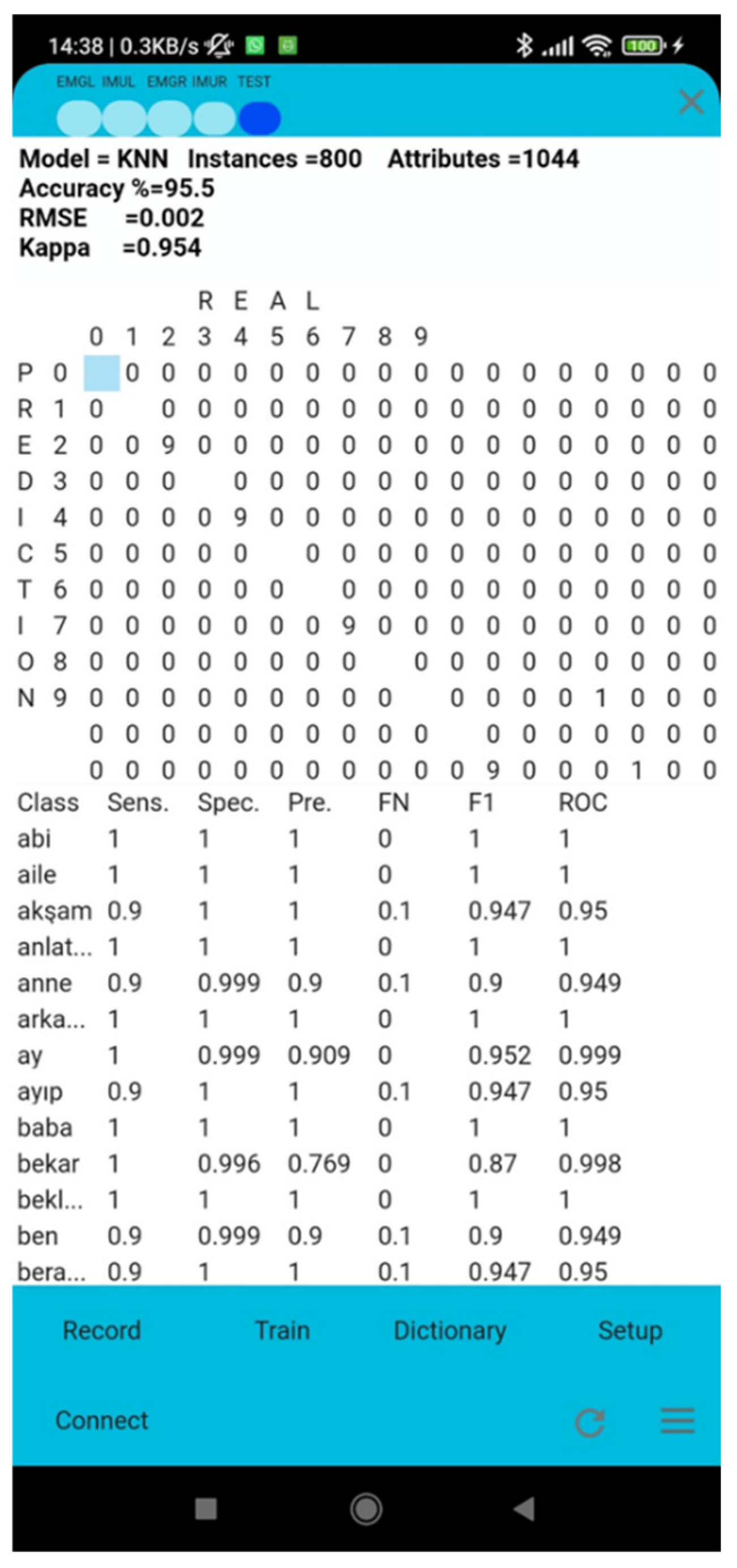
| k-Nearest Neighbor (KNN) | 95.5000 | 0.9542 | 0.0020 |
| Multi-Layer Perceptron (MLP) | 98.0000 | 0.9797 | 0.0201 |
| Naïve Bayes (NB) | 87.6250 | 0.8747 | 0.0556 |
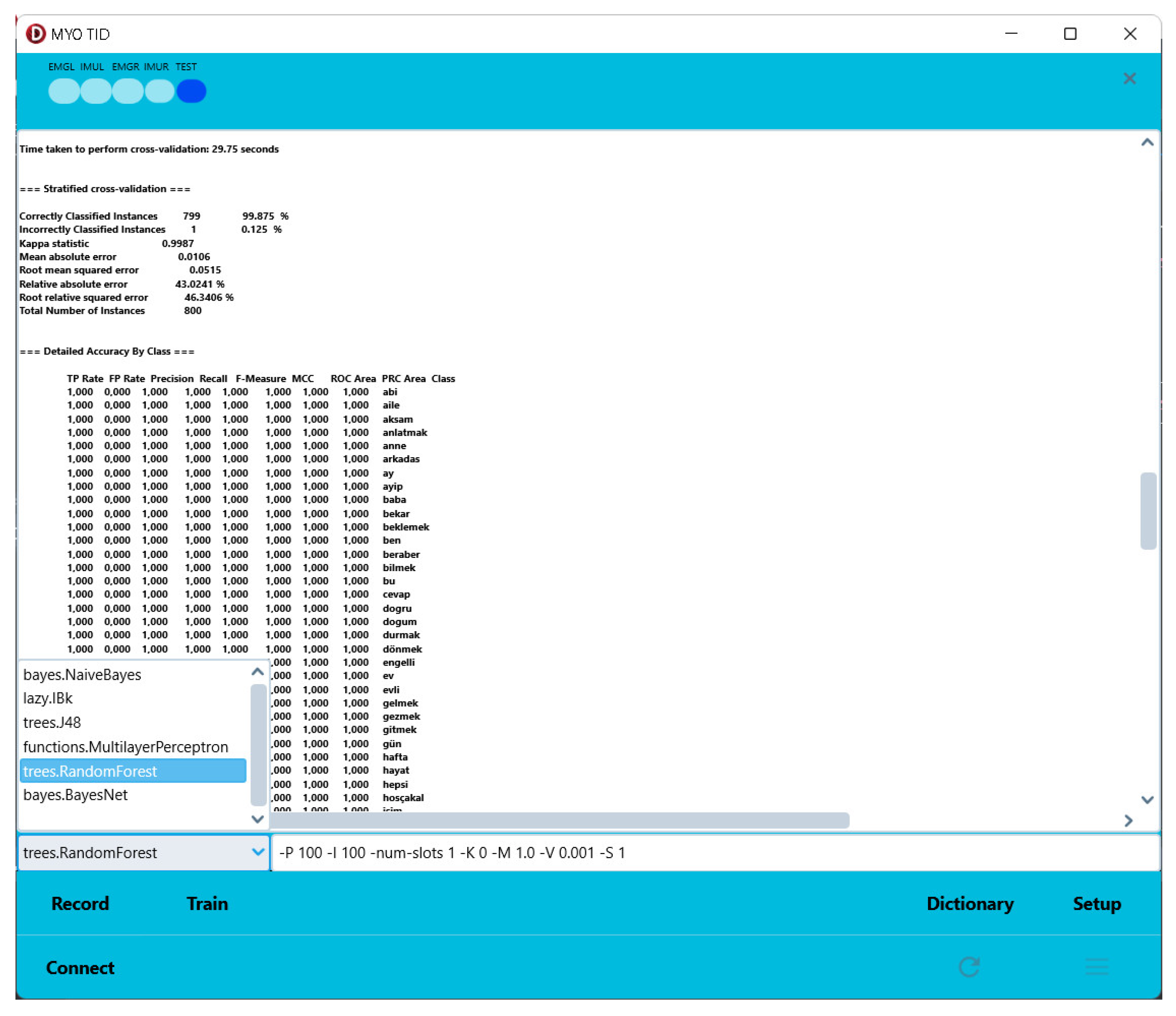
| Random Forest (RF) | 99.8750 | 0.9987 | 0.037 |
| Support Vector Machines (SVM) | 97.6250 | 0.9759 | 0.11 |
| Number of Records Used | Algorithm Accuracy (%) | ||||||
|---|---|---|---|---|---|---|---|
| Training | Test | MLP | WDL | RF | KNN | SVN | NB |
| 1 | 1 | 73.75 | 62.5 | 30 | 71.25 | 62.5 | 16.25 |
| 2 | 2 | 90.625 | 73.75 | 89.375 | 78.125 | 81.25 | 26.875 |
| 3 | 3 | 91.25 | 99.5833 | 99.1667 | 89.166 | 90 | 45.833 |
| 4 | 4 | 92.1875 | 99.375 | 98.75 | 91.25 | 90 | 61.875 |
| 5 | 5 | 95 | 99.75 | 99.25 | 92.25 | 94 | 67.75 |
| 6 | 4 | 95 | 91.5625 | 99.0625 | 95 | 95.312 | 75.312 |
| 9 | 1 | 97.5 | 96.25 | 100 | 97.5 | 98.75 | 85 |
Disclaimer/Publisher’s Note: The statements, opinions and data contained in all publications are solely those of the individual author(s) and contributor(s) and not of MDPI and/or the editor(s). MDPI and/or the editor(s) disclaim responsibility for any injury to people or property resulting from any ideas, methods, instructions or products referred to in the content. |
© 2024 by the authors. Licensee MDPI, Basel, Switzerland. This article is an open access article distributed under the terms and conditions of the Creative Commons Attribution (CC BY) license (http://creativecommons.org/licenses/by/4.0/).


