Preprint
Article

Design for an Orientation Algorithm of Ahrs Based on Gain Scheduling

Altmetrics

Downloads

106

Views

27

Comments

0

This version is not peer-reviewed

Submitted:

30 May 2024

Posted:

31 May 2024

You are already at the latest version

Alerts
Abstract
In recent years, the AHRS has become an important research area. In order to improve the orientation measurement accuracy of AHRS, this paper first expounds the algorithm principle of the AHRS. Then, aiming at the problem of poor stability of the traditional gradient descent method under high dynamics or large magnetic field interference, a gain-scheduled anti-interference AHRS orientation algorithm is designed. By using the switching architecture designed with this algorithm for gain scheduling, it can ensure stable performance while being subjected to apparent acceleration and ferromagnetic interference. Finally, experimental verification is conducted, and the experimental results show that: in the presence of interference, the roll angle error is 0.0350°, the pitch angle error is 0.0277°, and the yaw angle error is 0.9611°, thereby verifying the strong anti-interference performance of the gain-scheduled AHRS orientation algorithm proposed in this paper.
Keywords: 
Subject: Engineering  -   Control and Systems Engineering

1. Introduction

In recent years, the performance of Micro-Electro-Mechanical Systems (MEMS) has significantly improved. Due to their low cost, small size, and low energy consumption, their applications have increasingly proliferated [1]. One notable application is the construction of the Orientation and Heading Reference System (AHRS) [2]. AHRS, by measuring the orientation of moving objects, finds applications in numerous fields, including autonomous vehicles, Unmanned Aerial Vehicles (UAVs), Autonomous Underwater Vehicles (AUVs), human motion tracking, and autonomous robot control [3,4,5,6,7]. However, various interferences in practical applications affect the final system’s orientation measurement accuracy. Consequently, developing a robust anti-interference AHRS orientation algorithm has become a significant research topic [8,9].
In the process of sensor data fusion in AHRS, the commonly used methods are the Extended Kalman Filter (EKF) [10] and complementary filtering [11]. The EKF is widely employed in various aerospace projects. However, the complexity of the EKF algorithm is higher than that of complementary filtering, which increases the overall system cost [12]. In many practical applications, simpler filtering and compensation algorithms are preferred. Mahony [13] et al. proposed a nonlinear complementary filtering algorithm for fusing measurements from different sensors. Madgwick [14] et al. introduced a gradient descent method to estimate the system’s orientation. This method uses a linear complementary filter algorithm to combine the observed orientation from the system with the estimated orientation from the gyroscope to suppress drift. These fusion algorithms leverage the complementary characteristics of sensors to achieve more accurate and less noisy orientation and heading estimates. However, in high dynamic or magnetically disturbed environments, the apparent acceleration-induced horizontal orientation errors and magnetic field interference-induced heading errors can lead to inaccurate Euler angles calculations [15,16,17,18,19].
To address the challenges posed by acceleration and magnetic field interference, this paper proposes a gain-scheduled gradient descent algorithm based on the traditional gradient descent method. The gain is determined by a switching architecture based on magnetometer and accelerometer measurements, ensuring robust performance even in the presence of magnetic interference or sudden accelerations. The proposed scheme first dynamically adjusts the roll and pitch angle gains based on accelerometer measurements, then dynamically adjusts the yaw angle gain based on magnetometer measurements. Experiments conducted under acceleration and magnetic interference environments demonstrate that the gain-scheduled gradient descent method achieves more stable orientation resolution performance in complex usage scenarios.

2. Overview of Orientation and Heading Reference Systems

2.1. Principles of AHRS

The sensors comprising an Orientation and Heading Reference System (AHRS) include MEMS-based triaxial gyroscopes, MEMS-based triaxial accelerometers, and triaxial magnetometers. Within the AHRS, the initial step involves reading angular velocity, acceleration, and magnetic field strength data from each axis of the sensor units. This angular velocity data is subsequently processed to obtain changes in orientation. By combining this with the previous orientation of the vehicle, a new predicted Euler angles is derived.
However, errors such as gyroscopic bias, scale factor error, cross-axis coupling error, and noise inherent in the gyroscopes can cause the integrated orientation results to drift from the true values over time. Therefore, data fusion techniques are commonly employed to calculate Euler angles using accelerometer and magnetometer measurements, which compensate for the gyroscope-derived Euler angles and suppress gyroscopic drift.
The Euler angles derived from the gyroscopes can also provide boundary conditions for the accelerometer and magnetometer-derived Euler angles, particularly under high dynamic conditions or magnetic interference. The workflow of AHRS is illustrated in Figure 1.

2.2. Sensor Data Fusion

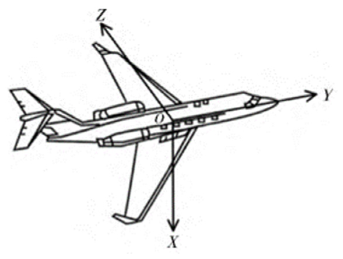
In this paper, the navigation frame is defined as the East-North-Up (O-ENU) frame. The X-axis of the body frame points to the right in the horizontal plane of the vehicle, the Y-axis points forward in the horizontal plane, and the Z-axis points vertically upward from the horizontal plane of the vehicle, as shown in Figure 2. To prevent singularities and reduce the overall computational load of the algorithm, quaternion-based orientation update method is adopted. The quaternion describing this orientation, q b n , is given by Equation (1).
q b n = [ q 1 q 2 q 3 q 4 ] T
The solving process of the traditional gradient descent method is as follows: first, the relationship between the angular velocity and quaternion derivative is calculated through numerical integration to determine the vehicle’s orientation. Then, the measurements from the magnetometer and accelerometer are taken as observation vectors, and the orientation is estimated using the gradient descent method. Finally, the orientation quaternion obtained from gyroscope integration and the orientation quaternion derived from the observation vectors are combined in a complementary filter to accurately estimate the vehicle’s orientation.
The angular rate measured by the gyroscope is denoted as ω i b b , which can be expressed in the form of Equation (2). Since MEMS gyroscopes are used in this paper, the Earth’s rotation rate ω i e b and the coupling angular velocity between the navigation frame and the earth frame ω e n b are relatively small, so the measured angular rate can be approximated as ω n b b . The relationship between the gyroscope-measured angular rate and the quaternion derivative q ˙ b n can be represented by Equations (3) and (4).
ω i b b = ω i e b + ω e n b + ω n b b
ω n b b = [ ω x ω y ω z ] T
q ˙ b n = 1 2 q b n [ 0 ω n b b ]
Under the assumption of a known initial orientation, the orientation of the body frame relative to the navigation frame at time t can be obtained by integrating the quaternion derivative equation, as shown in Equations (5) and (6):
q ˙ b n ( ω , t ) = 1 2 q b n ( e s t , t 1 ) [ 0 ω n b b ( t ) ]
q b n ( ω , t ) = q b n ( e s t , t 1 ) + q ˙ b n ( ω , t ) Δ t
In the above equations, q b n ( ω , t ) is the prior estimate quaternion of the orientation of the body frame relative to the navigation frame obtained from gyroscope data at time t, q ˙ b n ( ω , t ) is the derivative of the orientation quaternion measured by the gyroscope at time t, ω n b b ( t ) is the angular rate measured by the gyroscope at time t, Δ t is the gyroscope sampling period, and q b n ( e s t , t 1 ) is the posterior estimate of the orientation at the previous time step.
Using the Earth’s gravity vector and the geomagnetic vector as observation vectors, the value of the gradient f can be calculated. When the Earth’s gravity vector is used as an observation vector, its magnitude is g ^ n = [ 0 0 1 ] , and its direction is opposite to the navigation frame’s z-axis. Normalizing the accelerometer measurement a ^ b = [ a x a y a z ] , we can obtain Equations (7) and (8).
f g ( q b n , a ^ b ) = [ 2 ( q 2 q 4 q 1 q 3 ) a x 2 ( q 1 q 2 + q 3 q 4 ) a y ( 1 2 q 2 2 q 3 2 ) a z ]
J g ( q b n ) = [ 2 q 3 2 q 2 0 2 q 4 2 q 1 4 q 2 2 q 1 2 q 4 4 q 3 2 q 2 2 q 3 0 ]
When using the geomagnetic vector as an observation vector, the geomagnetic vector can be considered to have components on a horizontal axis and a vertical axis, with a magnitude of b ^ n = [ b x 0 b z ] . Normalizing the magnetometer measurement m ^ b = [ h x h y h z ] , we can obtain Equations (9) and (10).
f b ( q b n , b ^ n , m ^ b ) = [ b x ( 1 2 q 3 2 2 q 4 2 ) + 2 b z ( q 2 q 4 q 1 q 3 ) m x 2 b x ( q 2 q 3 q 1 q 4 ) + 2 b z ( q 1 q 2 + q 3 q 4 ) m y 2 b x ( q 1 q 3 + q 2 q 4 ) + b z ( 1 2 q 2 2 2 q 3 2 ) m z ]
J b ( q b n , b ^ n ) = [ 2 b z q 3 2 b z q 4 4 b x q 3 2 b z q 1 4 b x q 4 + 2 b z q 2 2 b x q 4 + 2 b z q 2 2 b x q 3 + 2 b z q 1 2 b x q 2 + 2 b z q 4 2 b x q 1 + 2 b z q 3 2 b x q 3 2 b x q 4 4 b z q 2 2 b x q 1 4 b z q 3 2 b x q 2 ]
The geomagnetic vector measured at time t, h ^ n ( t ) , can be obtained by rotating the normalized magnetometer measurement m ^ b ( t ) using the posterior estimate of the orientation from the previous time step q ^ b n ( e s t , t 1 ) , as shown in Equation (11). If the measured geomagnetic vector is incorrectly inclined, it can be corrected to the same inclination plane, as shown in Equation (12).
h ^ n ( t ) = [ 0 h x h y h z ] = q b n ( e s t , t 1 ) m ^ b ( t ) q b n ( e s t , t 1 ) T
b n ( t ) = [ 0 h x 2 + h y 2 0 h z ]
At this point, using the Earth’s gravity vector as an observation vector can suppress the divergence of the pitch and roll angles. To avoid the remaining yaw angle divergence, it is necessary to use both the Earth’s gravity vector and the geomagnetic vector as observation vectors. In this case, the objective function and the Jacobian matrix are given by Equations (13) and (14).
f g , b ( q b n , a ^ b , b ^ n , m ^ b ) = [ f g ( q ^ b n , a ^ b ) f b ( q ^ b n , b ^ n , m ^ b ) ]
J g , b ( q ^ b n , b ^ n ) = [ J g T ( q ^ b n ) J b T ( q ^ b n , b ^ n ) ]
According to the gradient calculation formula, at this point, f is given by Equation (15).
f g , b = J g , b T f g , b
Based on the gradient descent method, the gradient descent estimate at time t, q ^ b n ( , t ) , can be calculated from the posterior estimate of the orientation at the previous time step q b n ( e s t , t 1 ) through a single iteration, as shown in Equation (16).
q ^ b n ( , t ) = q b n ( e s t , t 1 ) μ t f f
By fusing the orientation quaternions q b n ( ω , t ) and q ^ b n ( , t ) obtained from Equations (6) and (16) respectively, the posterior estimate of the orientation quaternion at the current time t is derived. The fusion is performed as shown in Equation (17), where γ t is the weight applied to the orientation quaternion.
q b n ( e s t , t ) = γ t q ^ b n ( , t ) + ( 1 γ t ) q b n ( ω , t ) , 0 γ t 1
The optimal value of γ t is defined to ensure that the weighted divergence of q b n ( ω , t ) equals the weighted convergence of q ^ b n ( , t ) . This is defined by Equation (18), where β is the divergence rate of q b n ( ω , t ) , representing the magnitude of the quaternion derivative corresponding to the gyroscope measurement error.
( 1 γ t ) β = γ t μ t Δ t
Given that β is generally large, Equation (16) has an approximate expression as shown in Equation (19).
q ^ b n ( , t ) μ t f f
Substituting Equations (6) and (19) into Equation (17) yields Equations (20) and (21).
q b n ( e s t , t ) = q b n ( e s t , t 1 ) + q ˙ b n ( e s t , t ) Δ t
q ˙ b n ( e s t , t ) = q ˙ b n ( ω , t ) β f f
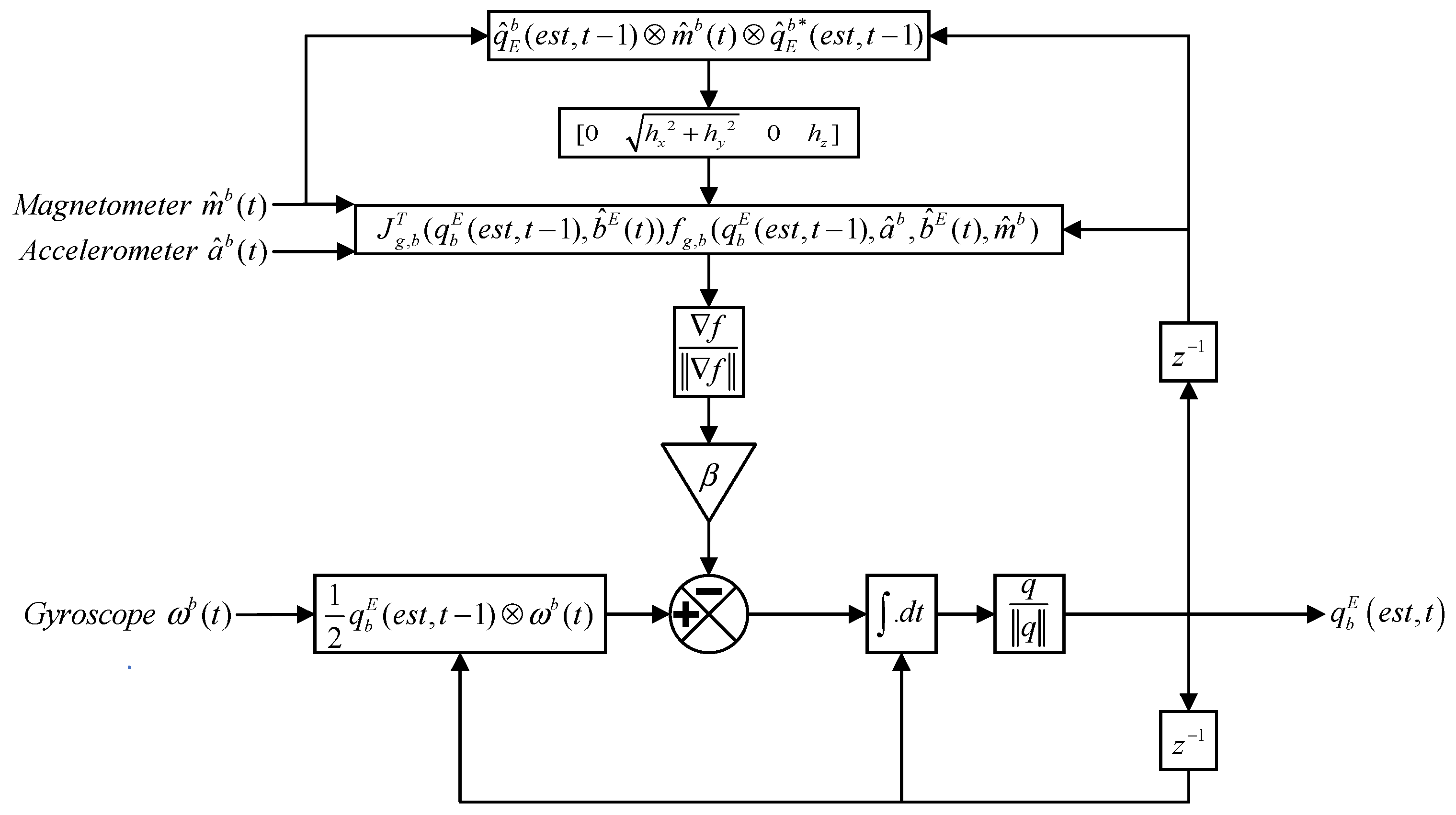
Figure 3 illustrates the block diagram of the implementation of the filtering algorithm.

3. Design of Gain-Scheduled Madgwick Algorithm

3.1. Issues with Traditional Madgwick Algorithm

For accelerometers, if the vehicle rotates, Coriolis acceleration due to the internal lever arm will be produced. This results in the accelerometer’s output containing components other than the Earth’s gravitational acceleration, thus affecting orientation measurement. Furthermore, changes in the apparent acceleration of the vehicle are another potential source of error. This means that the orientation derived from the accelerometer output is not reliable under dynamic conditions.
For magnetometers, metal structures and electrical equipment in the surrounding environment can produce magnetic interference, affecting the magnetometer’s performance. When the vehicle is near strong magnetic fields (such as power lines or railways), the magnetometer may become saturated, leading to errors. Such errors can reduce the accuracy of yaw angle computation or even produce incorrect results, leading to misalignment in updates.
In low dynamic conditions with minimal magnetic interference, the traditional gradient descent method can effectively suppress the divergence of the orientation angles computed by the gyroscope. However, when the magnetometer is affected by magnetic interference or the accelerometer experiences dynamic acceleration or platform vibrations, using the traditional gradient descent method for orientation fusion can result in significant errors, causing system misalignment.

3.2. Identifying Accelerometer Distortion

The accelerometer may be affected by vibrations from the platform on which it is mounted. In some applications, when the vehicle experiences dynamic acceleration, the accelerometer measures not only gravitational acceleration but also the vehicle’s motion acceleration. When the vehicle is in a high dynamic state, the orientation derived from the accelerometer becomes highly inaccurate, affecting the subsequent roll and pitch angles in orientation fusion.
To address the issue of accelerometer distortion, a gain factor is introduced in the roll and pitch channels. The determination of the gain factor is based on the level of acceleration perceived by the accelerometer to achieve optimal performance.
In the proposed scheme, different gains are applied to the gyroscope and accelerometer solutions based on the acceleration level (non-acceleration, low acceleration, and high acceleration modes) determined from the accelerometer measurements, as defined by Equation (25):
α ( k ) = | a x ( k ) 2 + a y ( k ) 2 + a z ( k ) 2 g |
The logic for switching the actual gain is as follows:
Non-acceleration mode: α ( k ) < 0.010 g , In this mode, the gravity vector measured by the accelerometer is observable, providing a good estimate of roll and pitch angles, with the accelerometer being given most of the weight during computation.
Low-acceleration mode: 0.010 g < α ( k ) < 0.5 g , In this mode, the uncertainty in the orientation estimated by the accelerometer must be considered, with the gyroscope given a higher weight during computation.
High-acceleration mode: α ( k ) > 0.5 g , In this mode, the system is in a high dynamic state. The roll and pitch orientations derived from the accelerometer measurements are highly erroneous, requiring the accelerometer gain to be set to 0, effectively turning off the accelerometer feedback, while the gyroscope is given full weight.
The gain scheduling logic for the roll and pitch angles derived from the accelerometer is illustrated in Figure 4.

3.3. Identifying Magnetometer Distortion

To prevent heading misalignment, it is necessary to reprocess the magnetometer measurements. By comparing the measured magnetic vector with the local geomagnetic vector, it is possible to identify if the geomagnetic vector has been disturbed. If the magnitude of the measured magnetic field significantly deviates from the expected value, the magnetometer data is considered unreliable.
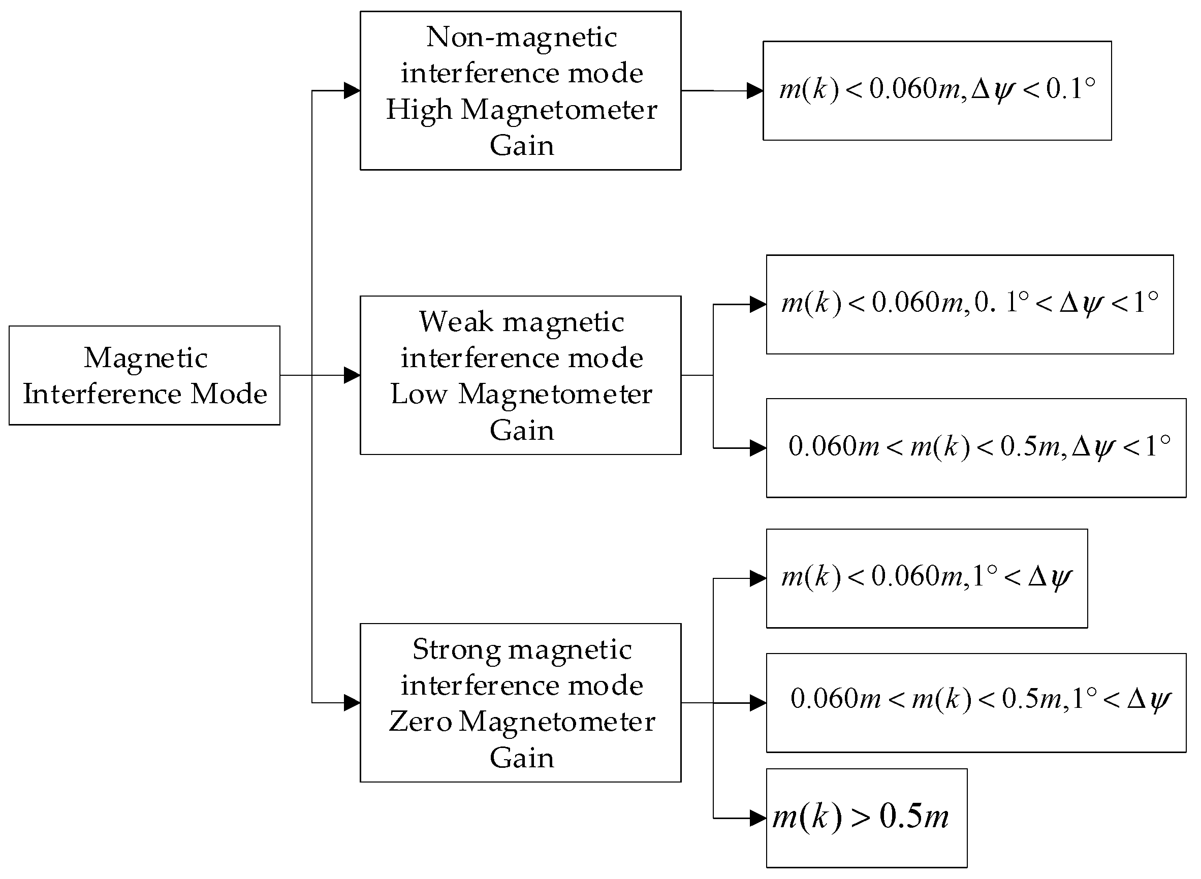
In this paper, a dynamic switching of the gain factor in the heading channel is implemented by introducing a gain factor, which adapts to different interference environments. The switching logic is initially based on the magnetic field strength level determined from the scalar dynamic magnetometer measurement m ( k ) , defined in Equation (22), where m is the local reference magnetic field value. The weight of the magnetometer in the calculation process is further determined by the difference Δ ψ between the heading angle derived from the magnetometer ψ m and the heading angle obtained from the gyroscope ψ g , defined in Equation (23).
m ( k ) = | m x ( k ) 2 + m y ( k ) 2 + m z ( k ) 2 m |
Δ ψ = | ψ g ψ m |
The thresholds for m ( k ) and Δ ψ are experimentally determined based on the characteristics of the gyroscope and magnetometer as well as application requirements. The logic for switching the filter gain includes the following scenarios:
Non-magnetic interference mode: m ( k ) < 0.060 m , 0.1 ° < Δ ψ < 1 ° . In this mode, the magnetometer provides a reliable heading estimate, and the magnetometer is given most of the weight in the calculation.
Weak magnetic interference mode: m ( k ) < 0.060 m , 0.1 ° < Δ ψ < 1 ° or 0.060 m < m ( k ) < 0.5 m , Δ ψ < 1 ° . In this mode, the uncertainty of the orientation estimated by the accelerometer must be considered, and the gyroscope is given a higher weight in the calculation.
Strong magnetic interference mode: 1 ° < Δ ψ or m ( k ) > 0.5 m . In this mode, the system is in a high interference state, and the heading estimate based on the magnetometer is not accurate. Therefore, the cutoff frequency is set to 0, effectively turning off the magnetometer feedback and relying entirely on the gyroscope.
In the presence of geomagnetic vector distortion, only the gravity vector should be used as an observation vector. Once the system is free from this interference, both magnetic and gravity vectors can be used for observation. Under different conditions, the gradient ∇f is given by Equation (24):
f { J g T f g S t r o n g   i n t e r f e r e n c e   m o d e J g , b T f g , b W e a k   i n t e r f e r e n c e   m o d e
The gain scheduling for the yaw angle obtained from the magnetometer is illustrated in Figure 5.

4. Experimental Validation and Analysis

Authors should discuss the results and how they can be interpreted from the perspective of previous studies and of the working hypotheses. The findings and their implications should be discussed in the broadest context possible. Future research directions may also be highlighted.

4.1. Experimental Design

To ensure the comprehensiveness of the orientation data calculated in this paper, the following experimental scenarios were designed. The test experiments in this study include the following scenarios: (1) non-interference scenario, (2) application of acceleration interference to the vehicle during the test, (3) application of magnetic interference to the vehicle during the test, and (4) simultaneous application of acceleration and magnetic interference to the vehicle during the test.
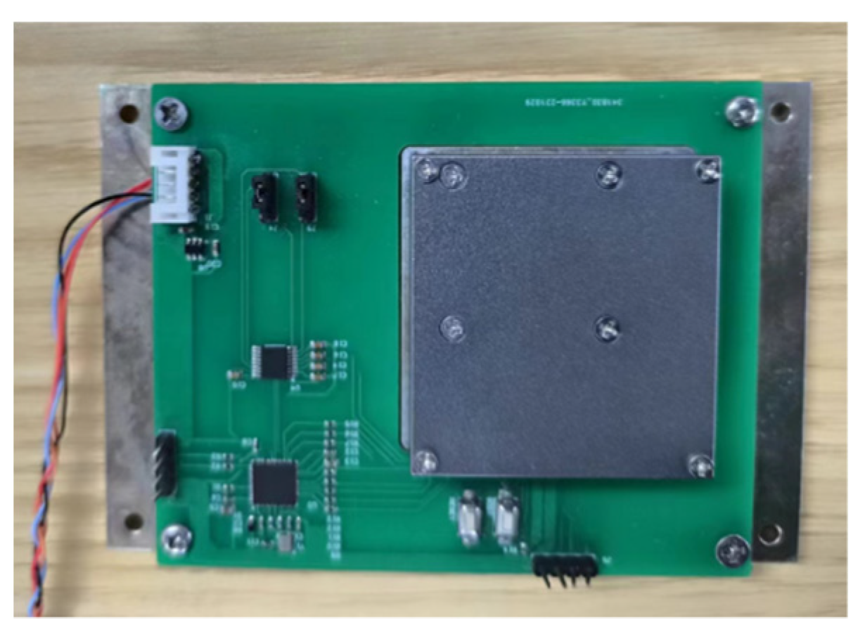
The AHRS used in the experiments includes three accelerometers, three gyroscopes, and three magnetometers, with digital interface output. This inertial measurement unit provides measurements of the vehicle’s triaxial linear acceleration, angular velocity, and Earth’s magnetic field. Table 1 provides a description of the sensor parameters in the AHRS. The AHRS prototype is shown in Figure 6.

4.2. Experimental Results

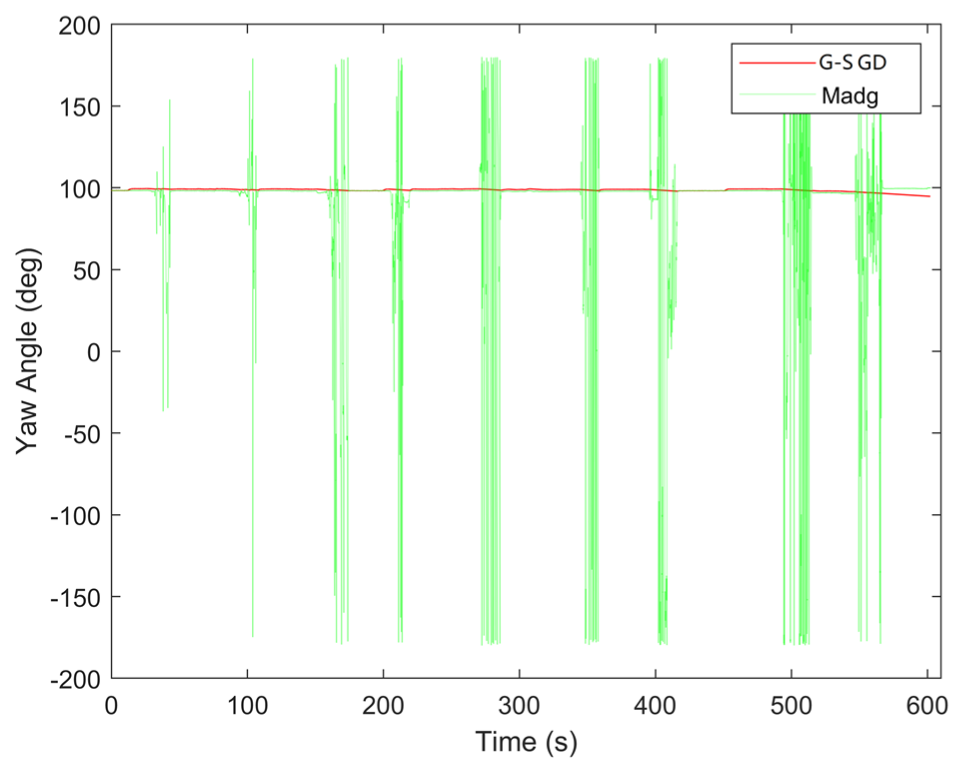
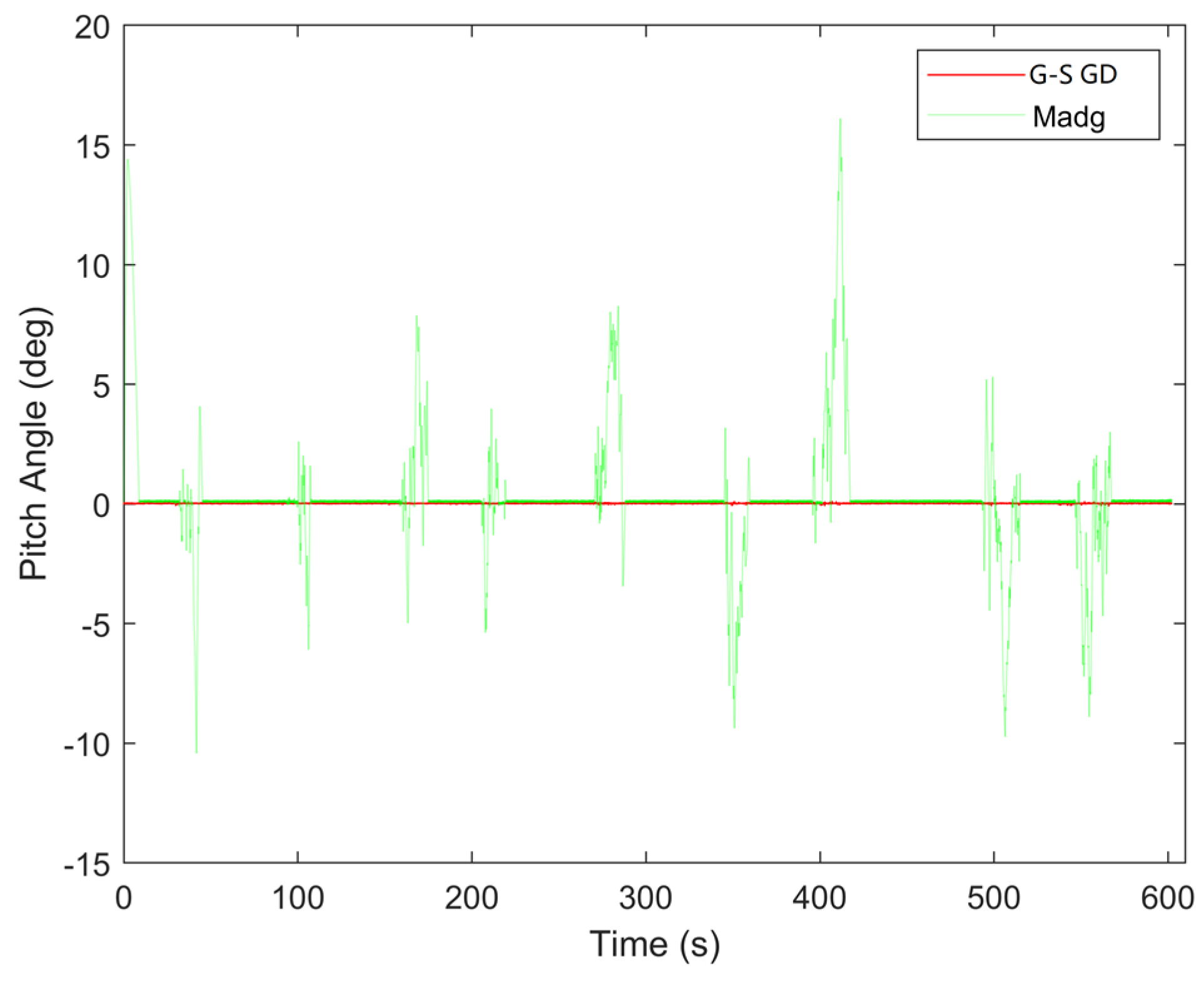
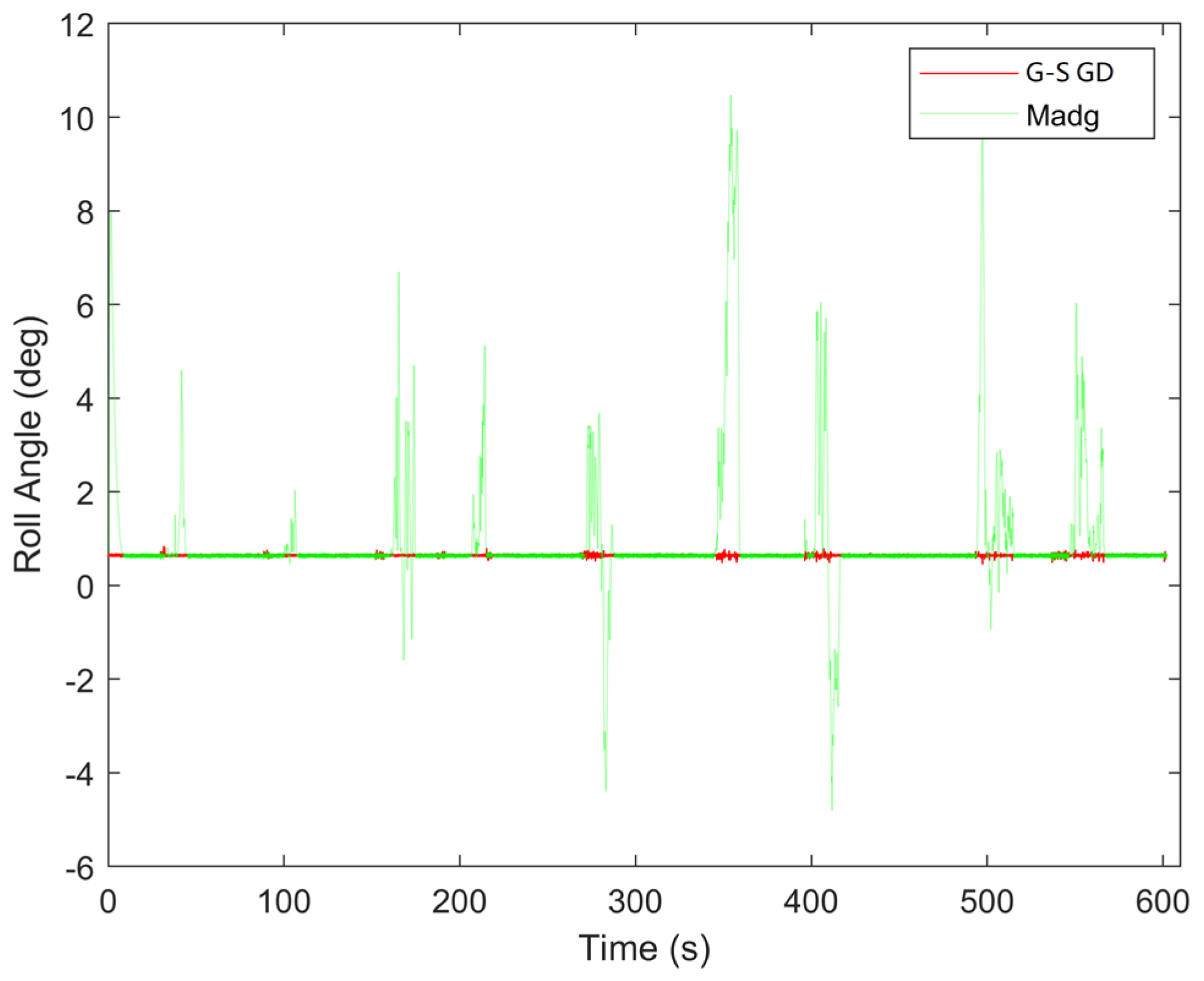
The proposed switching architecture was tested. The results of the gain-scheduled gradient descent method were compared with those of the traditional gradient descent method, as shown in Figure 7, Figure 8 and Figure 9.
In Figure 7, Figure 8 and Figure 9, the comparison between the two algorithms demonstrates that the traditional gradient descent method is prone to sudden changes in the calculated orientation angles due to external interference. In contrast, the algorithm proposed in this paper maintains stable orientation outputs even when subjected to external disturbances.
To validate the effectiveness of the orientation estimation, the results were calculated using the root mean square error (RMSE) method, as shown in Table 2. It is evident that the improved gradient descent method yields significantly better orientation calculation results compared to the traditional gradient descent method, with a substantial increase in accuracy.

5. Conclusions

This paper describes an orientation and heading reference system (AHRS) algorithm with strong anti-interference capabilities. The proposed gain-scheduled gradient descent method employs a switching architecture based on acceleration and magnetic field strength to determine the gain coefficients in the gradient descent algorithm. The proposed algorithm demonstrates excellent damping characteristics against drift errors from gyroscope measurements and noise and interference from accelerometer and magnetometer measurements.
In an interference environment, the roll angle error, pitch angle error, and heading angle error of the proposed method, based on the RMSE method, are 0.0350°, 0.0277°, and 0.9611° respectively. This indicates that the gain-scheduled gradient descent algorithm can achieve stable AHRS output.

Author Contributions

Conceptualization, R.J. and Y.W.; methodology, Y.J. and Y.W.; algorithm, R.J. and Y.W.; validation, R.J. and Y.W.; formal analysis, R.J. and Y.W.; investigation, R.J. and Y.W.; resources, R.J. and Y.W.; data curation, R.J. and Y.W.; writing original draft preparation, R.J.; writing—review and editing, R.J. and Y.W.; visualization, R.J. and Y.W. and Y.D. All authors have read and agreed to the published version of the manuscript.

Data Availability Statement

The data presented in this study are available on request from the corresponding author.

Conflicts of Interest

The authors declare no conflict of interest.

References

  1. Cai H Y, Zhao S L, Cui S Y, et al. Nine-axis inertial fusion with dynamic magnetic field calibration [J]. Optics and Precision Engineering, 2020, 28 (09): 2007-2016.
  2. Liu Y, Yang Y, Xu J T. Orientation estimation algorithm combining complementary filtering and Kalman filtering fusion [J]. Journal of Xi’an University of Posts and Telecommunications,2021,26(04):98-104. [CrossRef]
  3. Huang L L, Hu P F, Cao X, et al. Research on robot orientation estimation based on extended Kalman filtering algorithm [J]. Modern Machinery, 2023, (04): 13-16. [CrossRef]
  4. Mo L, Long S Y, Huang R, et al. Design of orientation estimation algorithm for small-scale aircraft based on quaternion combined with PI filtering [J]. Automation and Instrumentation,2023,(05):31-33.
  5. Zhang N, Cui H K, Xu W Z. Application of improved gradient descent method in inertial positioning orientation estimation of underground pipelines [J]. Wireless Interconnection Technology, 2023, 20 (12): 69-73.
  6. Liu H, Shi Z X, Shen Y Y, et al. Delayed orientation compensation algorithm for plant protection UAV based on improved ESKF. Journal of Instrumentation, 1-8 [2024-04-22].
  7. Han D, Sun W, Chen L, et al. Adaptive extraction algorithm for gravity acceleration in situ drilling orientation measurement. Journal of Instrumentation, 2022, 43 (02): 17-25.
  8. Liao K N, Guo Y Y. Research on orientation estimation method based on improved adaptive Kalman filtering [J].
  9. Lu Y J, Chen Y D, Zhang X D, et al. Research on orientation information fusion method based on extended Kalman filtering. Journal of Instrumentation, 2020, 41 (09): 281-288.
  10. Odry Á, Kecskes I, Sarcevic P, et al. A novel fuzzy-adaptive extended Kalman filter for real-time orientation estimation of mobile robots [J]. Sensors, 2020, 20(3): 803. [CrossRef]
  11. Zhu P, Chen W P, Shi Y, et al. Orientation estimation method based on Mahony filtering and EKF fusion [J]. Sensors and Microsystems, 2023, 42 (12): 160-163+168.
  12. Wu Y L, Xing H Y, Hou T H, et al. High-precision orientation estimation based on improved adaptive extended Kalman filtering [J]. Journal of Detection and Control, 2023, 45 (06): 69-76.
  13. Mahony, R., Hamel, T., & Pflimlin, J. M. Nonlinear complementary filters on the special orthogonal group [J]. IEEE Transactions on Automatic Control, 2008, 53(5): 1203-1218. [CrossRef]
  14. Madgwick, S. O. H., Harrison, A. J. L., & Vaidyanathan, R. Estimation of IMU and MARG orientation using a gradient descent algorithm[C]∥2011 IEEE International Conference on Rehabilitation Robotics, IEEE, 2011: 1-7.
  15. Zong Y K, Su S J, Gao Y H. Orientation fusion algorithm based on multi-source IMU and particle filter optimization [J]. Instrument Technique and Sensor, 2023, (08): 88-95.
  16. Wang T, Kuang N L, Zhong S, et al. Array MEMS-IMU axis alignment and orientation estimation method based on quaternion vector averaging [J]. Journal of Chinese Inertial Technology,2023,31(07):642-649.
  17. Chen J W, Tao J, Chen H Q, et al. Research on diagnostic filtering method for heading angle of magnetic sensor. Journal of Instrumentation, 2022, 43 (03): 194-201.
  18. Wang B S, Lu Y J, Zhang X D, et al. Orientation estimation method based on adaptive step size gradient descent with Butterworth low-pass filtering [J]. Journal of Detection and Control, 2023, 45 (03): 116-120+125.25.
  19. Qiao M Y, Li W N, Yao W H, et al. Orientation estimation algorithm based on multi-sensor fusion using SRCKFw detection [J]. Journal of Electronic Measurement and Instrumentation, 2023, 37 (05): 127-135.
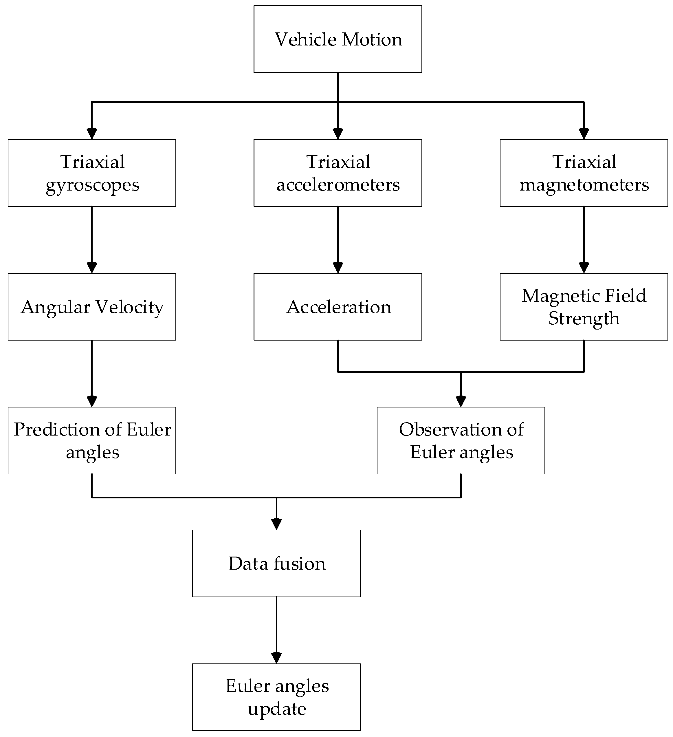
Figure 1. The workflow of AHRS.
Preprints 107899 g001
Figure 2. Body frame.
Preprints 107899 g002
Figure 3. Block diagram representation of the orientation filter.
Preprints 107899 g003
Figure 4. Accelerometer Gain Scheduling Logic Block Diagram.
Preprints 107899 g004
Figure 5. Magnetometer Gain Scheduling Logic Block Diagram.
Preprints 107899 g005
Figure 6. Data acquisition equipment.
Preprints 107899 g006
Figure 7. Yaw angle determination from gain-scheduled gradient descent method.
Preprints 107899 g007
Figure 8. Pitch angle determination from gain-scheduled gradient descent method.
Preprints 107899 g008
Figure 9. Roll angle determination from gain-scheduled gradient descent method.
Preprints 107899 g009
Table 1. Sensor parameters.
Gyroscope Accelerometer Magnetometer
Dynamic Range ±450 (deg/s) ±16(g) ±2 (Gauss)
Zero Bias Stability 2(deg/h) 0.1 (mg) -
Zero Bias Repeatability 4 (deg/s) 10 (mg) -
Random Walk 0.1(deg/s /√h) 0.02 (m/s/√h) -
Resolution - - 120 (μGauss)
Noise Intensity - - 5 (μGauss)
Table 2. RMSE of orientation angles.
Gain-Scheduled Madgwick Algorithm Madgwick Algorithm
Yaw Angle 0.9611° 42.7712°
Pitch Angle 0.0277° 2.3537°
Roll Angle 0.0350° 1.3440°
Disclaimer/Publisher’s Note: The statements, opinions and data contained in all publications are solely those of the individual author(s) and contributor(s) and not of MDPI and/or the editor(s). MDPI and/or the editor(s) disclaim responsibility for any injury to people or property resulting from any ideas, methods, instructions or products referred to in the content.
Copyright: This open access article is published under a Creative Commons CC BY 4.0 license, which permit the free download, distribution, and reuse, provided that the author and preprint are cited in any reuse.
Prerpints.org logo

Preprints.org is a free preprint server supported by MDPI in Basel, Switzerland.

Subscribe

© 2024 MDPI (Basel, Switzerland) unless otherwise stated