2. Materials and Methods
A quality control system is designed using artificial intelligence tools capable of receiving MDF boxes or any of their components and carrying out the inspection of four critical quality aspects: dimensions, color, weight, and labeling.
The system validation will be performed with two boxes of different sizes. Consequently, the pieces will also be of two different sizes.
Table 1 shows the specifications for the boxes:
Table 2 shows the specifications for the pieces:
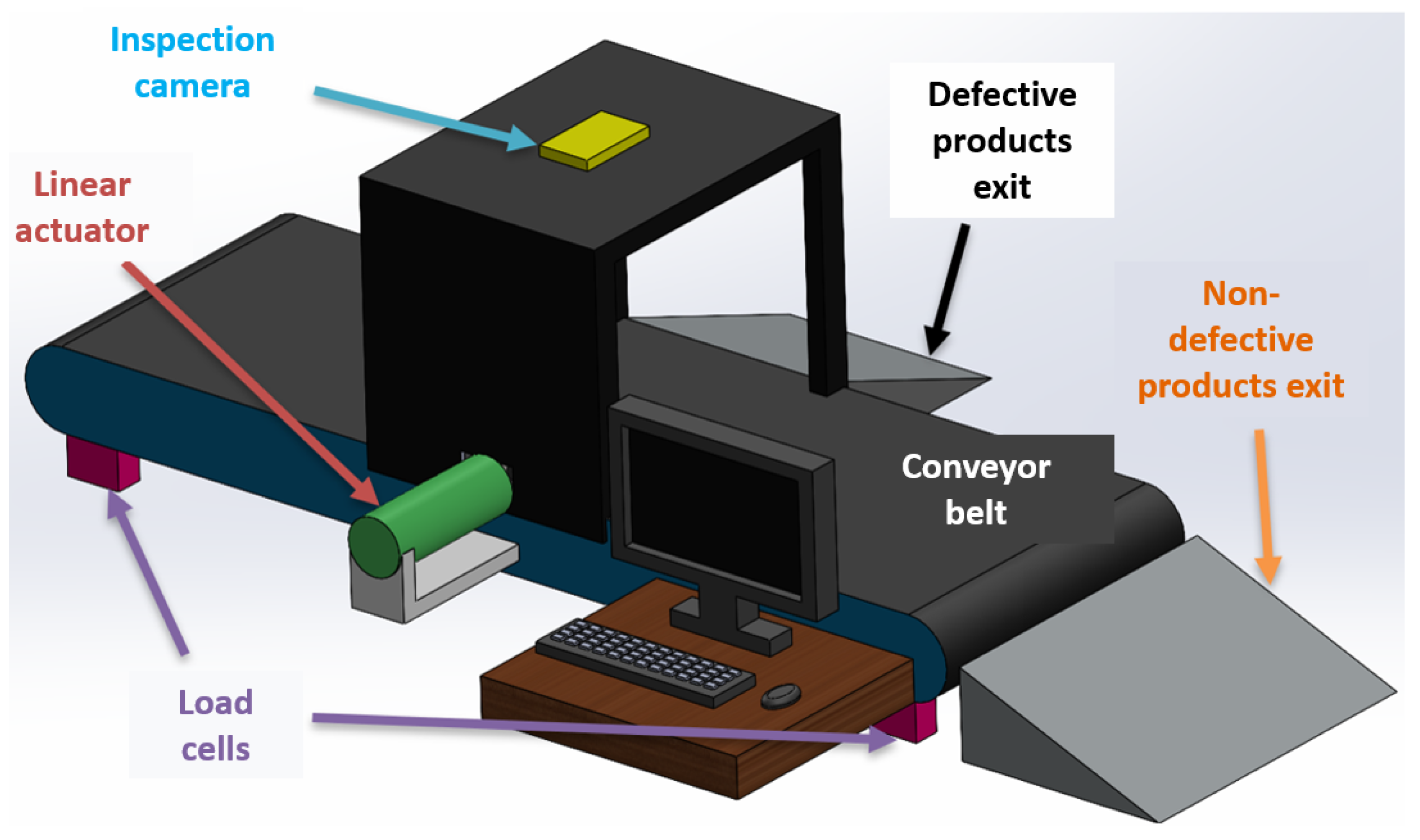
Figure 1 shows a construction diagram; a closed inspection station ensures a controlled lighting environment. At the top of this station, there will be a high-definition camera to analyze the length and width dimensions, and an ultrasonic sensor located next to the camera will analyze the height dimension of the box. A linear actuator will push the object being analyzed if it does not meet the minimum requirements. The conveyor belt will move the pieces from the beginning to the end of the belt to remove them through a tray. Four load cells will be placed under the entire belt, which will provide the weight of the product, considering that the weight of the boxes is much smaller than that of the entire belt, it is expected that the maximum measurement errors will be in this part of the inspection process.
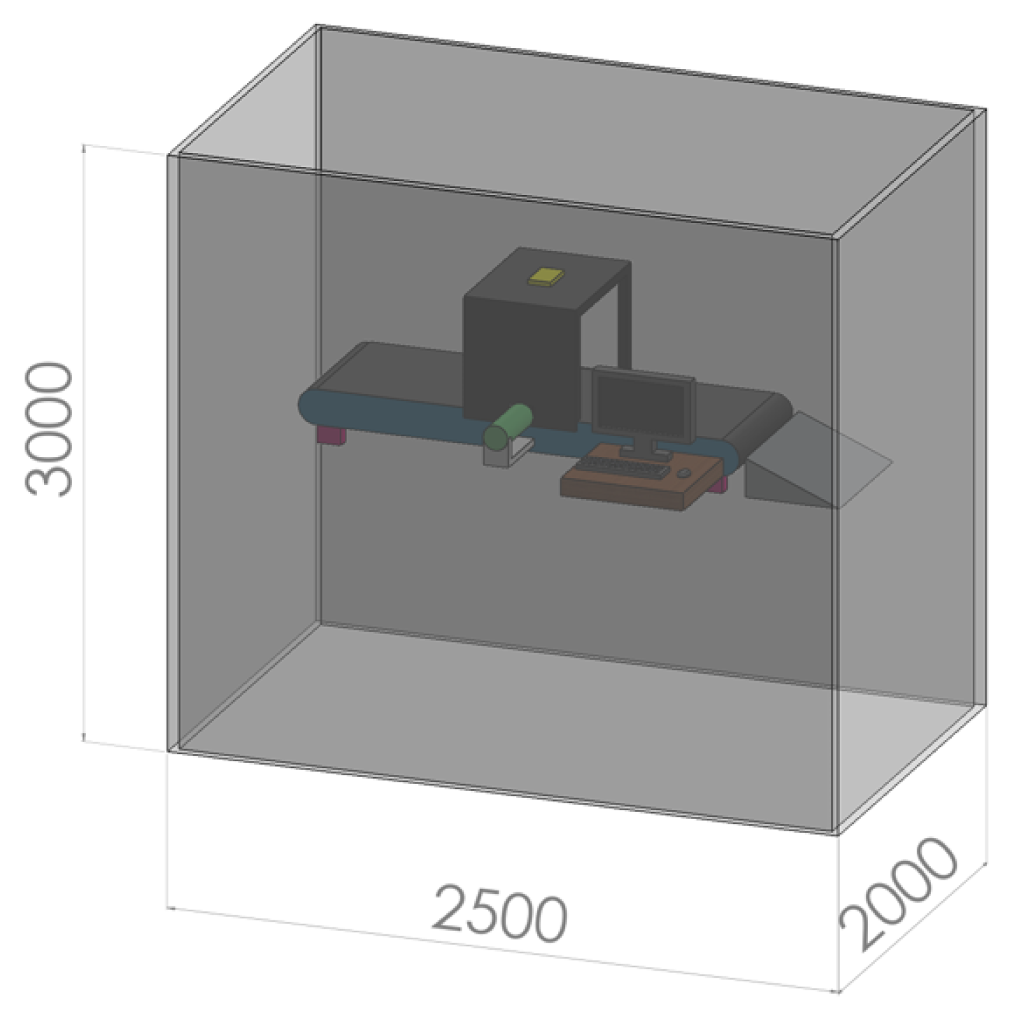
The workspace assigned for this station will be 2.0 x 2.5 x 3.0 [m] (see
Figure 2), however, the entire space will not be occupied since the project can be carried out in a smaller area. The conveyor belt will be one meter long considering the maximum dimensions of the boxes, which simplifies the design and helps reduce costs and construction time.
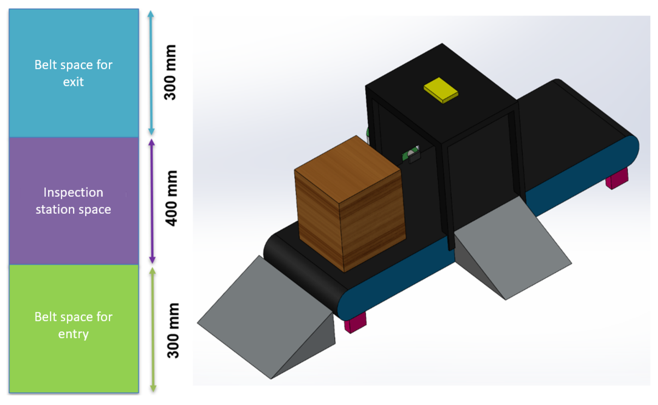
The camera needs to be placed at a height that allows the widest possible viewing range while respecting the assigned space. Therefore, the length of the conveyor belt is divided into three parts: in the intermediate section, the analysis by artificial vision will be carried out, so the inspection station, which will measure 400 [mm], will be located in this space. The belt will be left with free spaces at the ends for products to enter and exit, with each side having 300 [mm] as shown in
Figure 3.
2.1. Requirements Definition
Capable of transporting pieces and wooden boxes of 15 and 20 [cm].
Fits the assigned space of 2.0 x 2.5 x 3.0 [m].
Capable of inspecting critical quality aspects (dimensions, color, weight, and labeling) of the pieces or boxes.
The duration of the quality inspection of a piece or box must be shorter compared to the time it takes for a manual inspection.
Have two control modes: automatic and manual.
Have an interface that allows monitoring and control of the station.
The station must be able to communicate with a cloud server in real time.
The aesthetic design of the cabin should maintain the color scheme.
2.2. Technical Specifications
2.3. Concept Generation
For concept generation, information was gathered on various options, of which the three most relevant for each stage were selected, rating them with a score of 5 as the best in terms of meeting the selection criteria and a score of 1 as the worst.
2.3.1. Transportation System
Table 3 compares the different applicable options for this system.
The transportation system will be built with a roller system with a DC motor because it has good speed at an excellent cost, and furthermore, its torque will be sufficient to move pieces and wooden boxes.
2.5. Mechanical Subsystem
The mechanical subsystem is responsible for transporting the pieces and wooden boxes. The product to be inspected starts its journey from the beginning of the conveyor belt, then arrives at the inspection area, and finally, the classifier arm pushes it depending on whether the product is defective or not. Therefore, this subsystem will be composed of three components: the transportation system, the inspection area, and the classifier arm, as shown in
Figure 4.
2.6. Electronic Subsystem
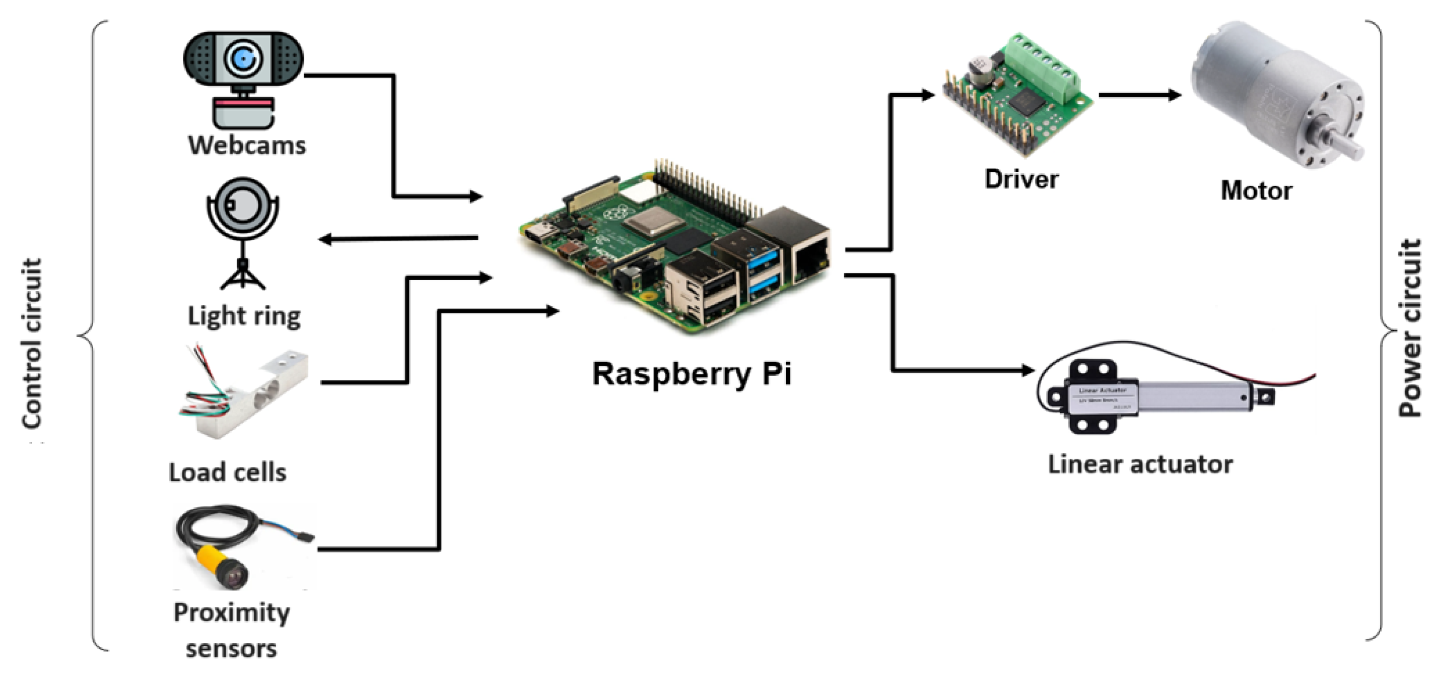
The electronic subsystem consists of two main circuits: the power circuit and the control circuit, as shown in
Figure 5. The power circuit is responsible for energizing the conveyor belt motor and the linear actuator, while the control circuit comprises the sensors and the image acquisition system components. The device that processes the sensor information and sends control signals to the actuators will be a Raspberry Pi. The entire subsystem will be powered by a DC voltage source.
2.7. Control Subsystem
As shown in
Figure 6, this subsystem consists of three stages: inspection area, classifier algorithm, and HMI interface. The first stage is responsible for placing the object in the inspection area with the conveyor belt and acquiring images with the webcam.
The second stage corresponds to the classifier algorithm, which will be programmed in Python with the OpenCV library. The algorithm must be capable of inspecting the critical quality aspects indicated in
Table 4.
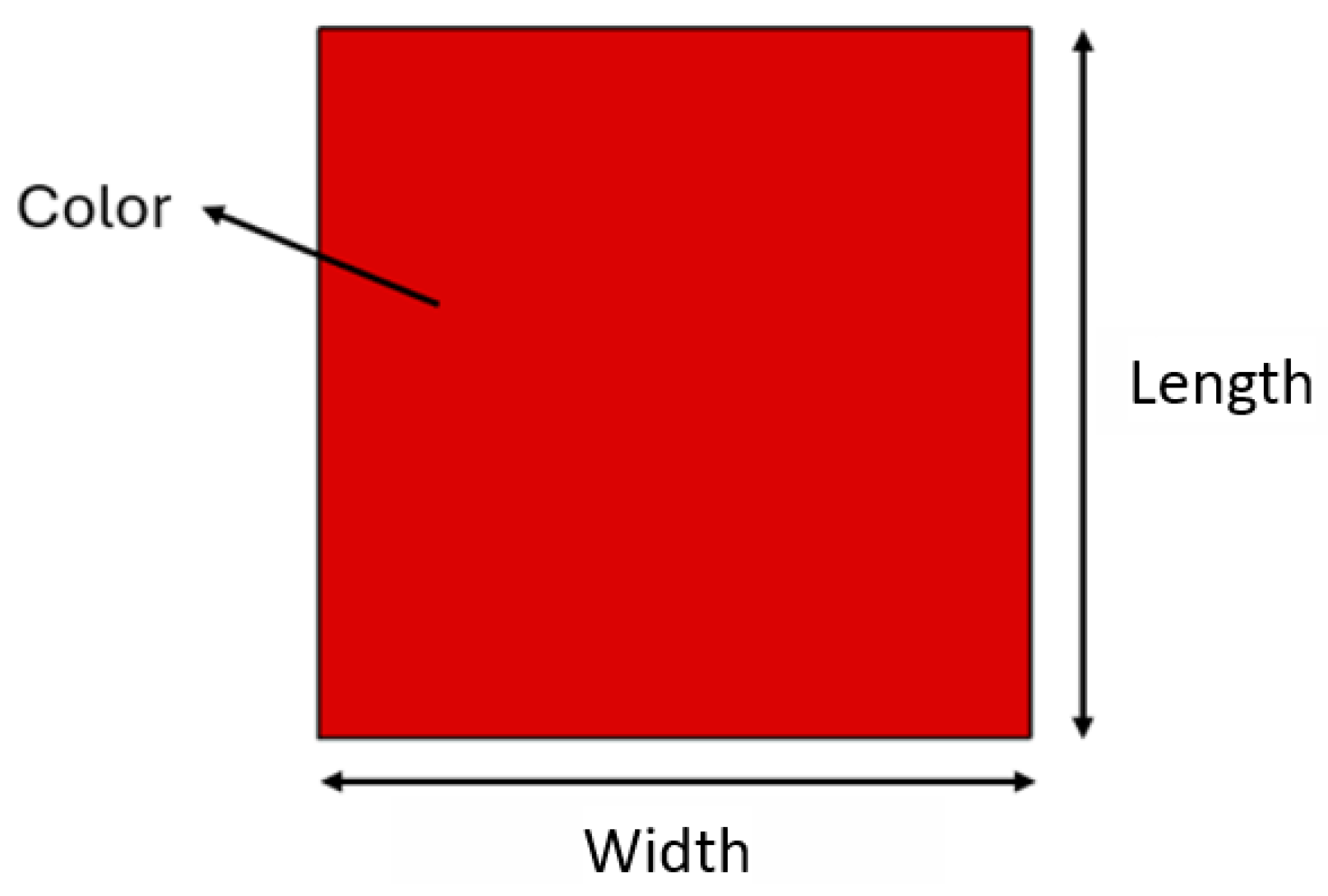
Figure 7 shows the critical quality aspects inspected in a piece, while
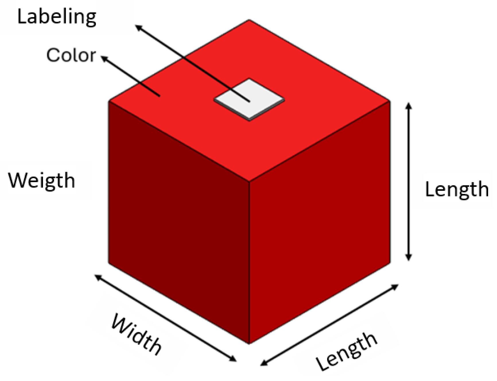
Figure 8 shows the critical aspects inspected in a box.
2.8. Detailed Design
A highly efficient solution for the inspection and selection of wooden boxes in a quality control system is the use of a conveyor belt. By facilitating process automation and reducing manual intervention, it enables the continuous flow of boxes on the conveyor belt. This solution also allows for precise synchronization with inspection tools, including a machine vision camera and load cells, resulting in accurate evaluation of each box. The use of actuators to separate good and bad boxes, control of speed, and synchronization of the conveyor belt ensures sufficient time for inspection. Optimal precision and efficiency in quality control can be achieved through the perfect integration of sensors and control devices, and the versatility of the conveyor belt in handling boxes with different properties makes it a fundamental option.
Figure 9 shows a diagram of the chosen solution to implement the mechanical subsystem. A conveyor belt will be used to pass the wooden boxes one by one to an inspection station where the camera analyzes some critical quality aspects for product evaluation. There will be two branches on the conveyor belt to separate defective products from non-defective ones.
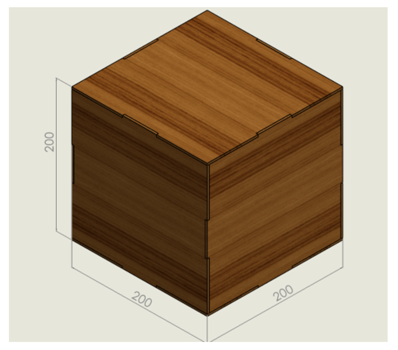
For the design of this conveyor belt, it is necessary to define the type of product to be used, and as previously mentioned, prefabricated wooden boxes will be classified. First, the volume occupied by the most critical case in terms of box dimensions will be defined. According to the information provided by the previous stations that will develop the manufacturing, the maximum volume of each product will be a 200 mm sided cube, as shown in
Figure 10, so this measure will be considered for the construction of the mechanical subsystem.
With the dimensions of the object, the total dimensions of the system are specified and must not exceed 2.5 m x 2 m in terms of the top view (plan view), and 3 m in height limitation.
2.8.1. Material Selection and Dimensions for the Conveyor Belt and Rollers
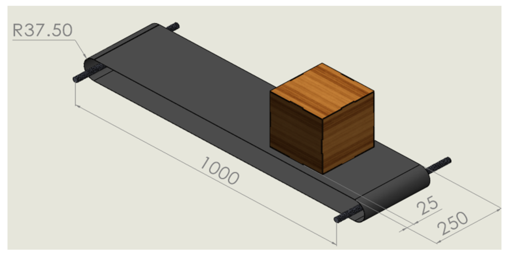
The first factor to consider for the conveyor belt will be its measurements. Since the box has a maximum length of 200 mm, it was decided to make it so that there is a reasonable distance on each side to prevent the box from hitting objects outside the belt’s limit during its movement. Therefore, the belt will have a dimension of 250 mm, with a distance of 25 mm on each side of the box. The length will be 1 meter from axle to axle of both rollers. PVC pipe with a diameter of 70 mm will be used for the rollers, so the internal radius of the belt will be 37.5 mm. Adding these dimensions, which can be seen in
Figure 11, results in the total belt length needed to be 2.2 meters, and it was decided that after cutting, the belt will be vulcanized so that it does not have seams that could cause friction or any jam in the system.
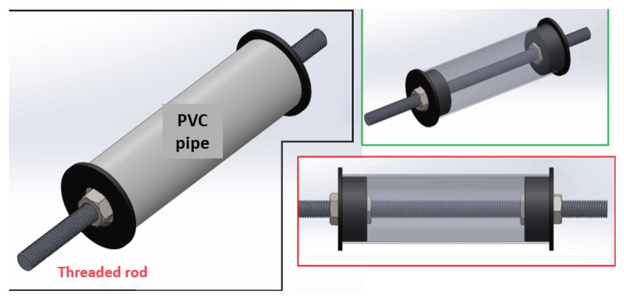
For the material selection of the rollers, it was considered that they should be as light as possible because the entire belt system must be mounted on load cells for weight measurement. Therefore, a 70 mm diameter PVC pipe was chosen. For coupling and connection to bearings, a ¾ inch threaded rod was used, centered on the pipe with the help of 3D-printed caps and corresponding nuts for the threaded rod. This will ensure that the pipe is well attached to the threaded rod, so when traction is applied to one of these rollers to move the belt, there will be no slippage and the belt will not start to slip. The parts that make up this roller system can be seen in
Figure 12.
The materials selected are because the box does not weigh even 1 kg. However, for weight analysis, an extra object will be placed to allow sensing and verifying its value. The rollers and the conveyor belt are not subjected to very high loads. It is considered that the objects will not fall, producing impact loads, nor will the system be subjected to adverse climatic conditions. Therefore, very simple materials can be chosen for the construction of the belt and rollers.
2.8.2. Motor Sizing and Power Transmission System
For conveyor belt systems, the estimated power required by the motor can be calculated using the following expression:
Where:
P: Required power
C: Dirt compensation coefficient, which is 13 for a length of 1 m between rollers.
R: Roller friction coefficient, which is 0.02 for the PVC material of the belt.
L: Length of the conveyor belt [m].
Q: Actual transport capacity.
: Belt inclination angle, 0 for a completely horizontal belt.
The actual transport capacity Q is calculated with the expression:
Where:
v: Belt advance speed, which for this application is set at 0.4 m/s.
p: Weight of the belt plus the weight of the rollers in kg.
D: Hourly capacity of the belt.
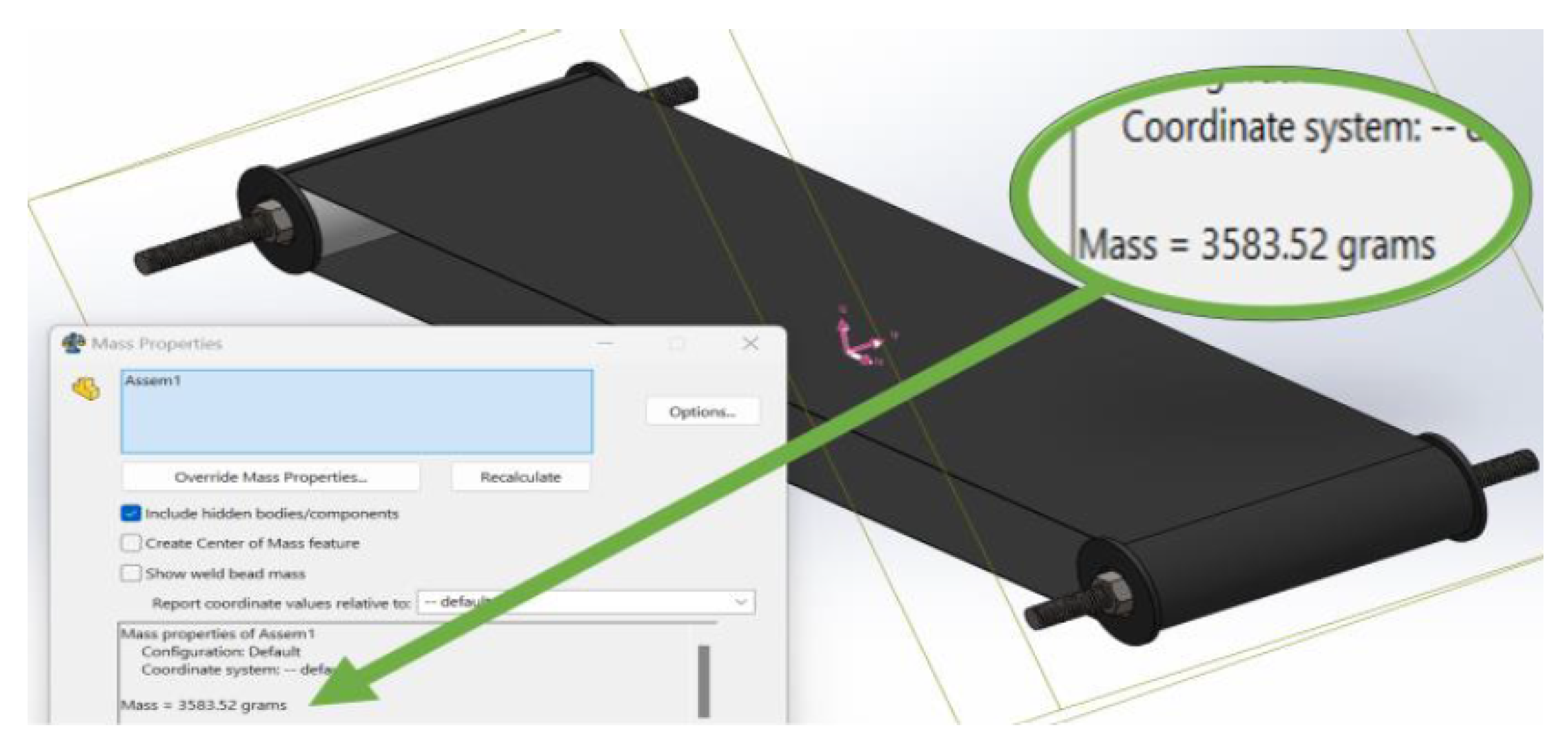
The value p, the weight of the belt along with the rollers, is defined using the CAD design.
Figure 13 shows the required value; the weight is 3583.52 grams, approximately 3.58 kg, so:
The value of D is a factor provided by the belt manufacturer. For this PVC belt with the defined characteristics, it is:
Therefore, substituting values:
Now the required power to choose the motor is calculated:
This means that theoretically, any motor with a power greater than 5.85 W would work for this application. However, to avoid oversizing and due to the low power requirement, a DC motor with a gearbox that can support the load is chosen. The selected motor is a POLOLU 37Dx57L, which operates at 12V with a 100:1 reduction, having a power of 8W.
Table 5 shows the characteristics of the selected motor:
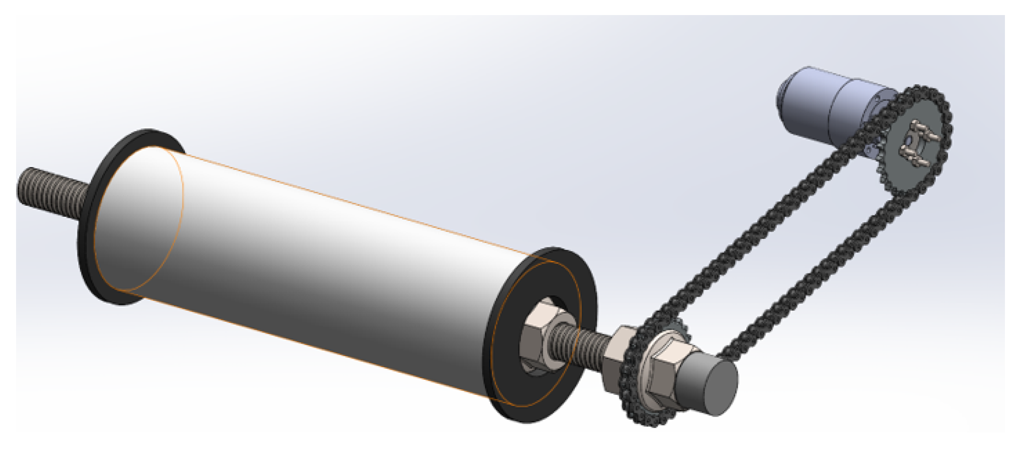
For the power transmission system, a chain with sprockets is chosen because it is a very cheap and easy-to-implement solution. It also allows control over the chain tension. The chain will be recycled from a 150
displacement Chinese motorcycle spare part. This chain is used in the motorcycle to synchronize and move the rocker arms of the cylinder head that open and close the intake and exhaust valves. The sprocket on the camshaft will also be recycled, and two are needed to make a complete power transmission system as shown in
Figure 14.
A mount for the geared motor will be designed. This mount will be bolted to one of the side faces of the conveyor belt, which will have specially designed holes to allow horizontal displacement, so that sufficient chain tension can be generated for power transmission before tightening the bolts.
2.9. Design of the Metal Structure
All previously described components must be mounted on a metal support for proper operation. Before starting to design the entire structure, some key aspects need to be considered.
When working with a conveyor belt and a trapezoidal belt, it is necessary to take into account that the proper functioning of these systems greatly depends on the tension generated between the support shafts. This means ensuring that the structure allows one of the supports to slide to tension the conveyor belt and the trapezoidal belt if necessary.
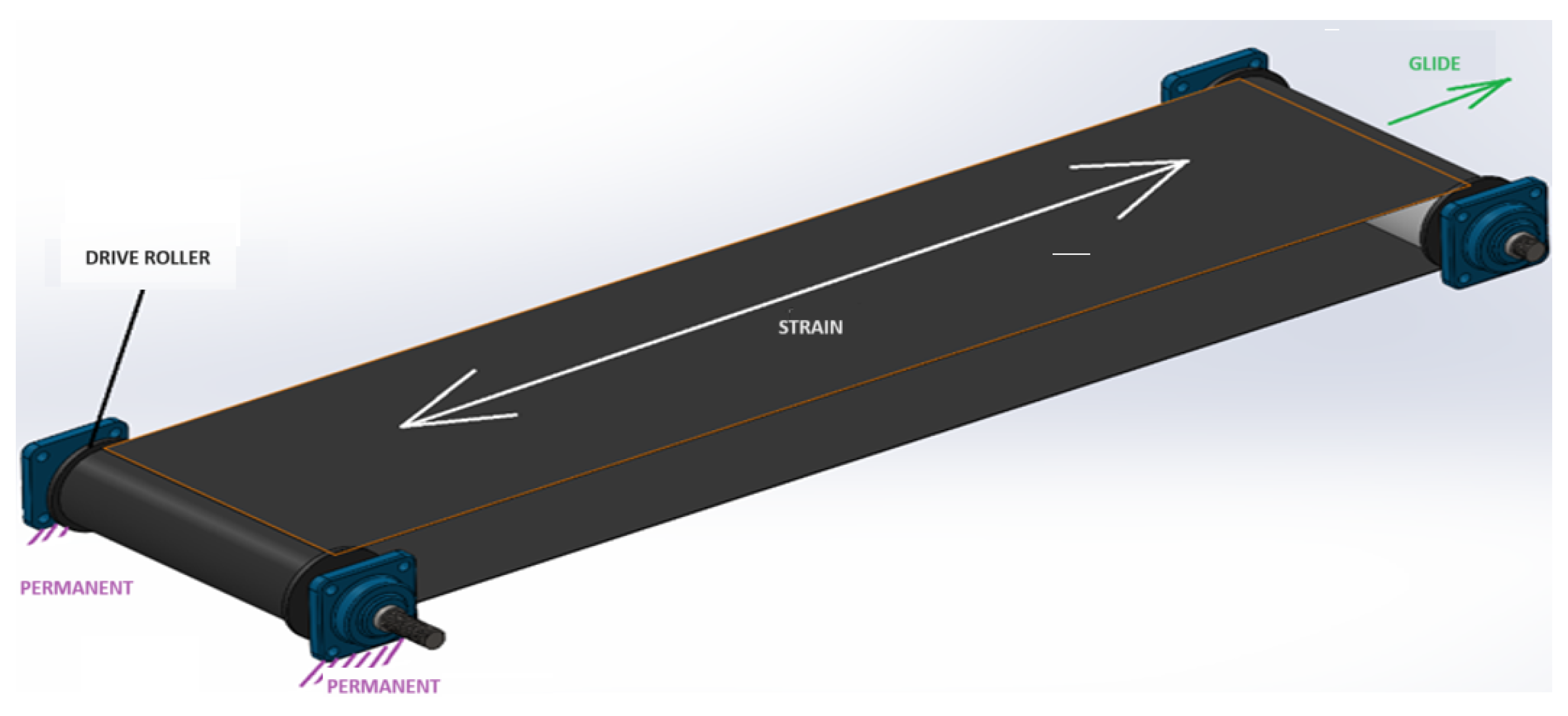
First, the type of coupling to be used for the rollers to rotate freely with minimal friction must be defined. It was decided to use pillow block bearings at the ends of the threaded rods to rotate freely. Additionally, the pillow blocks have small set screws to ensure proper shaft grip on the internal bearing. A pair of these pillow blocks will be fixed to the drive roller, which will be connected to the transmission pulley, while the other end, corresponding to the free roller, will need considerable sliding to tension the belt if necessary, as illustrated in
Figure 15.
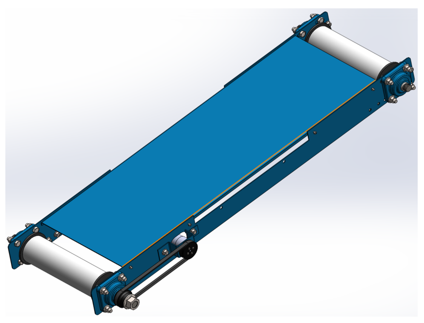
To achieve this, a metal sheet structure will be used, which will have the profile and holes necessary to allow this movement. It was decided that the sheet will have fixed holes on one side and elongated slots on the other end to slide the pillow block in case more tension is required. This profile can be seen in
Figure 16.
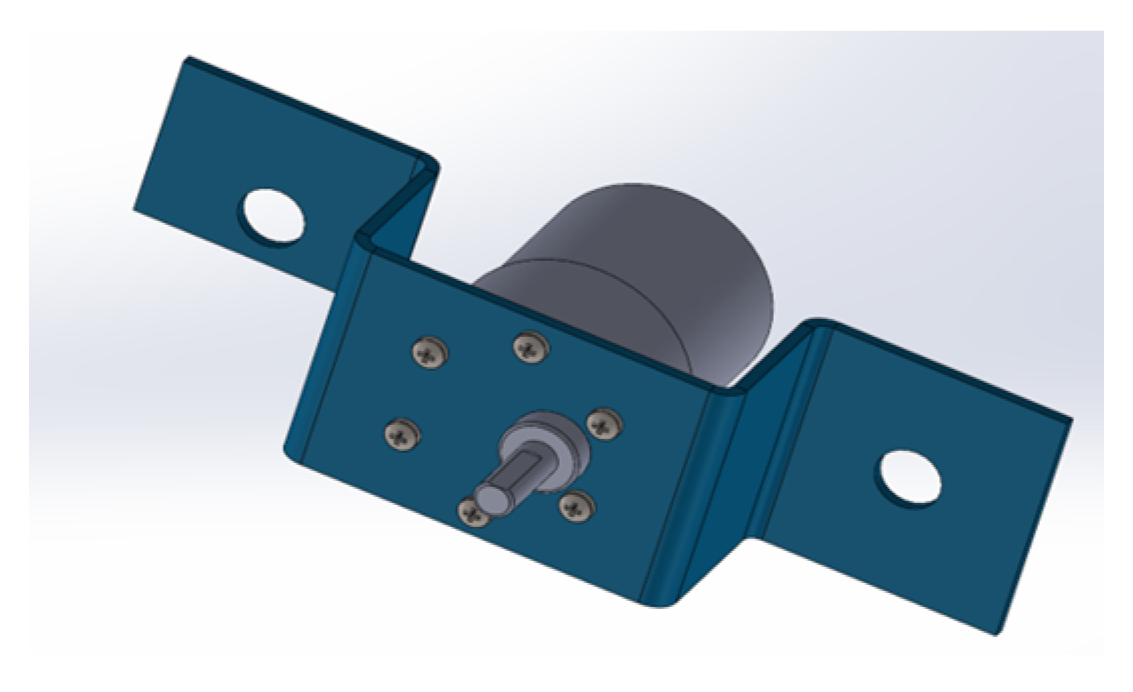
The same analysis must be done for the trapezoidal belt. However, first, the possibility of mounting the motor on a small metal structure to keep it fixed and make its mounting and sliding for belt tensioning more feasible will be analyzed. This piece was designed according to the threaded holes that the motor has on the front and can be seen in
Figure 17.
With this piece, proper mounting and tension adjustment of the chain will be performed. It is only necessary to slightly modify the slots on the previously shown metal sheet so that this piece, along with the motor, can be assembled, as shown in
Figure 18.
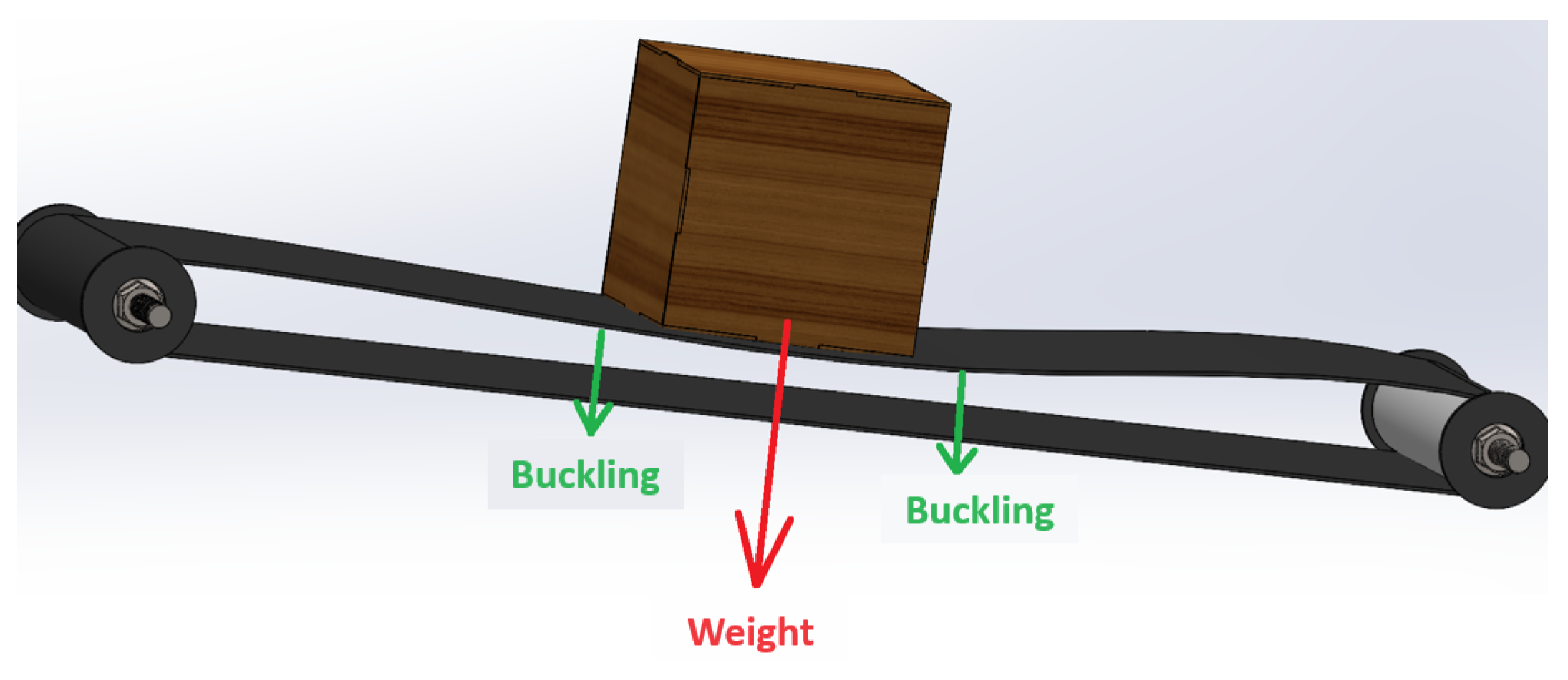
Another problem that arises when placing objects on the conveyor belt is the sagging caused by the weight of the objects themselves, as shown in
Figure 19.
To solve this, a metal plate can be placed to support the belt, so that when objects are placed on it, this effect, which can distort measurements taken by machine vision, does not occur. The design will be as shown in
Figure 20.
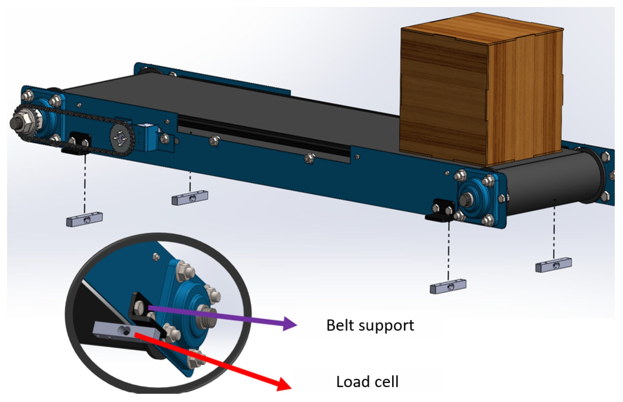
Due to the need to measure the weight of what is placed on the conveyor belt, a simple and effective method has been developed to incorporate four load cells proportionally placed in the belt body. The sum of the detections in each of the load cells will give the total weight placed on it, as shown in
Figure 21.
3. Results and Discussion
The load cells will be bolted to the supports, which in turn will be bolted to the body of the conveyor belt. The other end of the load cells will be attached to a tubular structure designed to support all the previously designed components and also accommodate space for installing the main CPU, a power control board, a monitor, a keyboard, and a mouse.
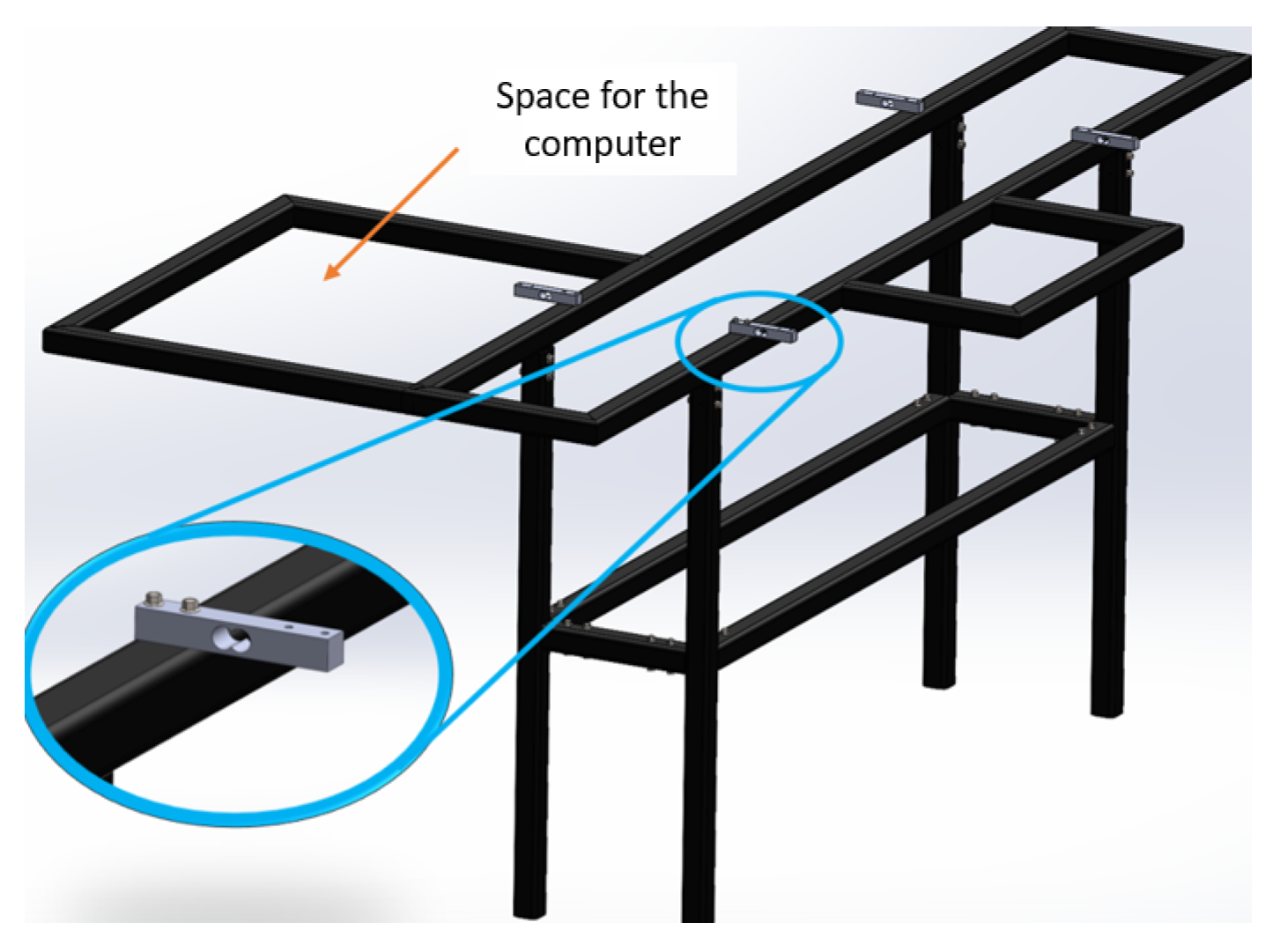
Figure 22 shows a design of the structure to be implemented, which will have four legs and will be made to fit the load cells positioned under the belt to perfectly align with the pre-drilled holes.
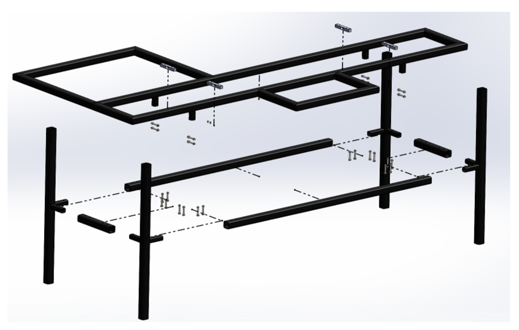
To facilitate the movement of the entire structure and make it modular, everything will be built with bolted joints instead of welded ones, allowing easy assembly and disassembly of the entire system. There will be a main frame specifically welded to maximize space usage, with four legs connected to each other by crossbars located in the middle of their length.
Figure 23 visualizes all the parts of this structure and the positions of each component. The 20 mm square tubes welded to the 30 mm ones will fit inside them.
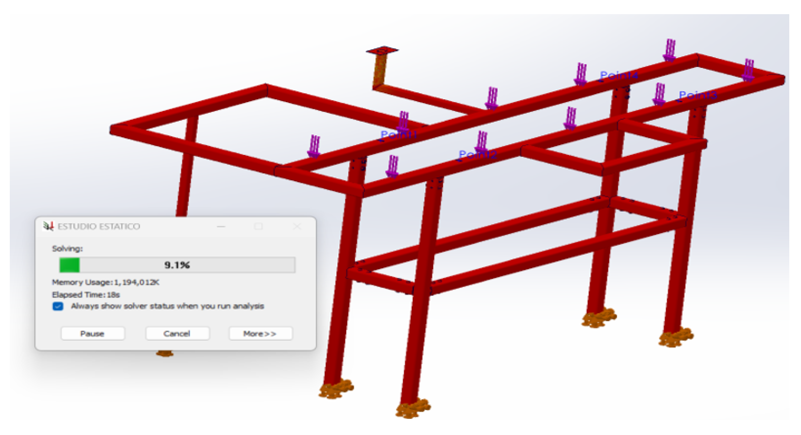
To verify if the structure will support the load, a finite element analysis is performed. Considering the belt and all accessories have a weight of 12 kg, the weight in Newtons is:
Half of this load is applied to each side of the tubular structure, as shown in
Figure 24. The bases of the legs will be fixed, and the analysis will be conducted with fine meshing.
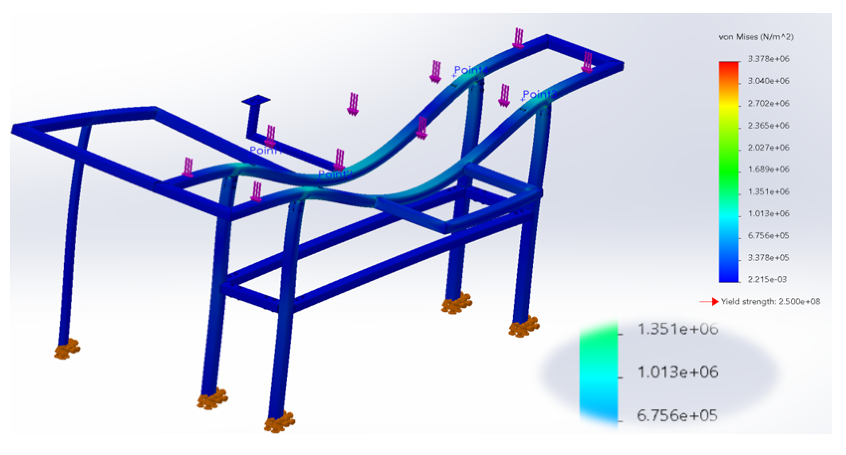
The Von Mises stresses are shown in
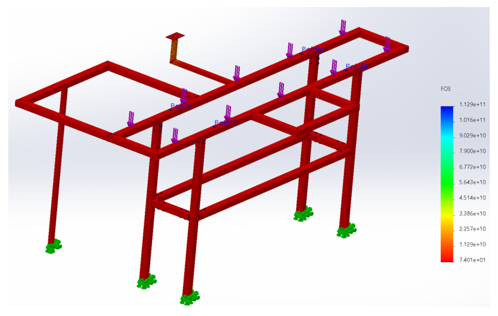
Figure 25, with the highest being 101.3 MPa.
In
Figure 26, the safety factor is shown, with the minimum being 74.01, indicating that the material is more than sufficient for the required application. However, the structure is made of A36 steel, a commercial structural steel, one of the simplest and cheapest in the industry.
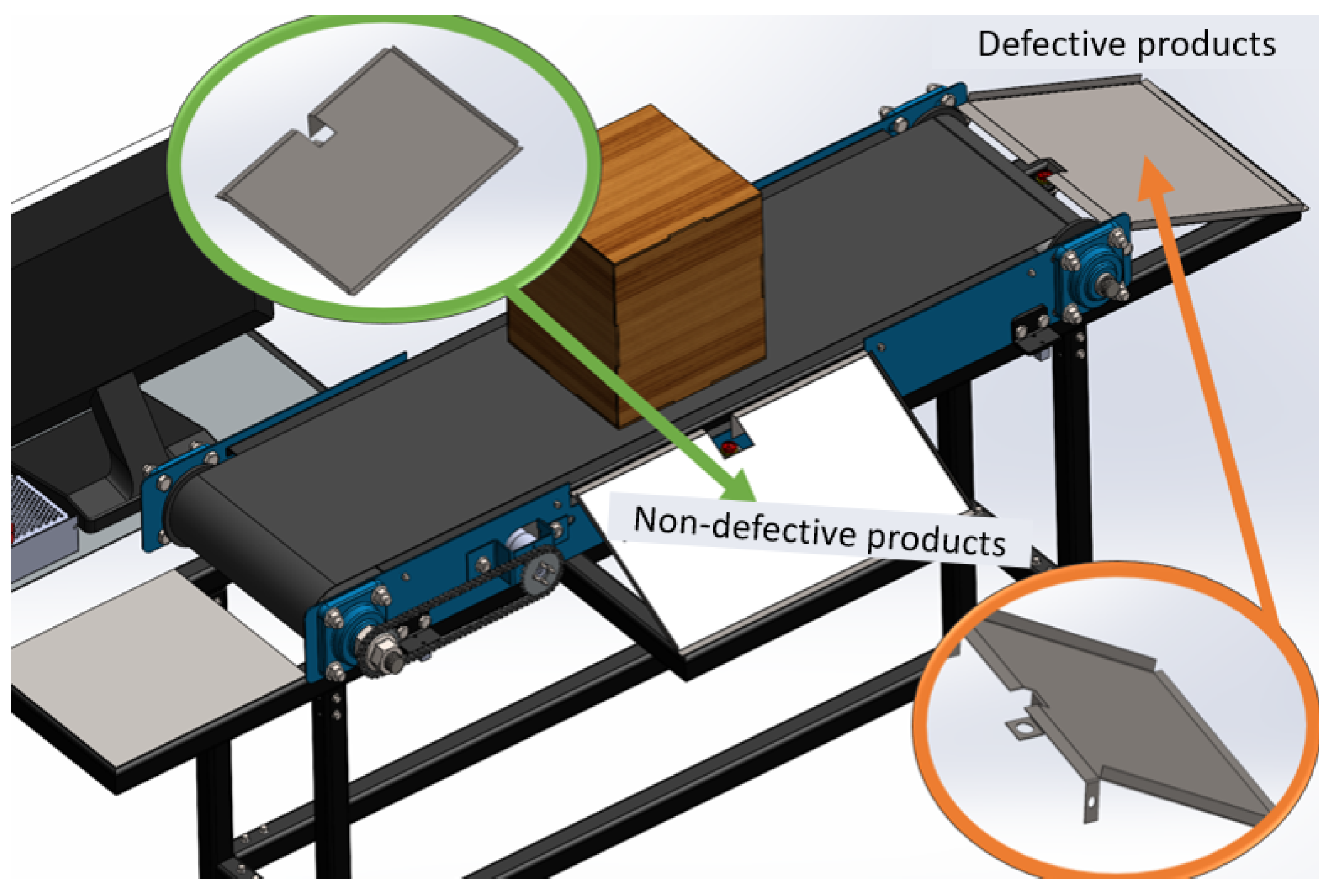
The primary function of this plant is to select boxes that meet the correct design specifications and separate those that do not. Therefore, two output ramps will be considered. One ramp will be for correct boxes, aligned with the belt and at the end, while the defective boxes ramp will be perpendicular to the belt, as shown in
Figure 27.
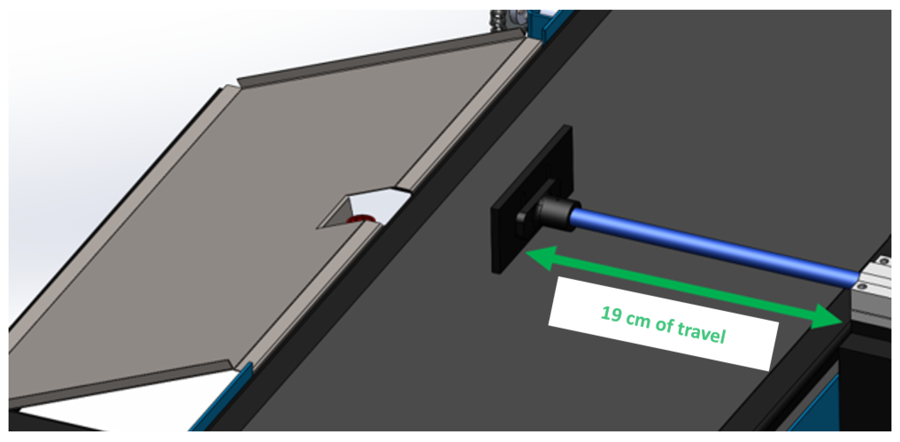
Defective boxes will be separated from the non-defective ones using a linear actuator that will push them onto the perpendicular ramp. A pusher piston is needed for this, and as previously analyzed in the conceptual design, a crank-slider mechanism will be used with parts printed in 3D. The required stroke length of 19 cm is ideal for any box or piece to be pushed to the defective products tray, as shown in
Figure 28.
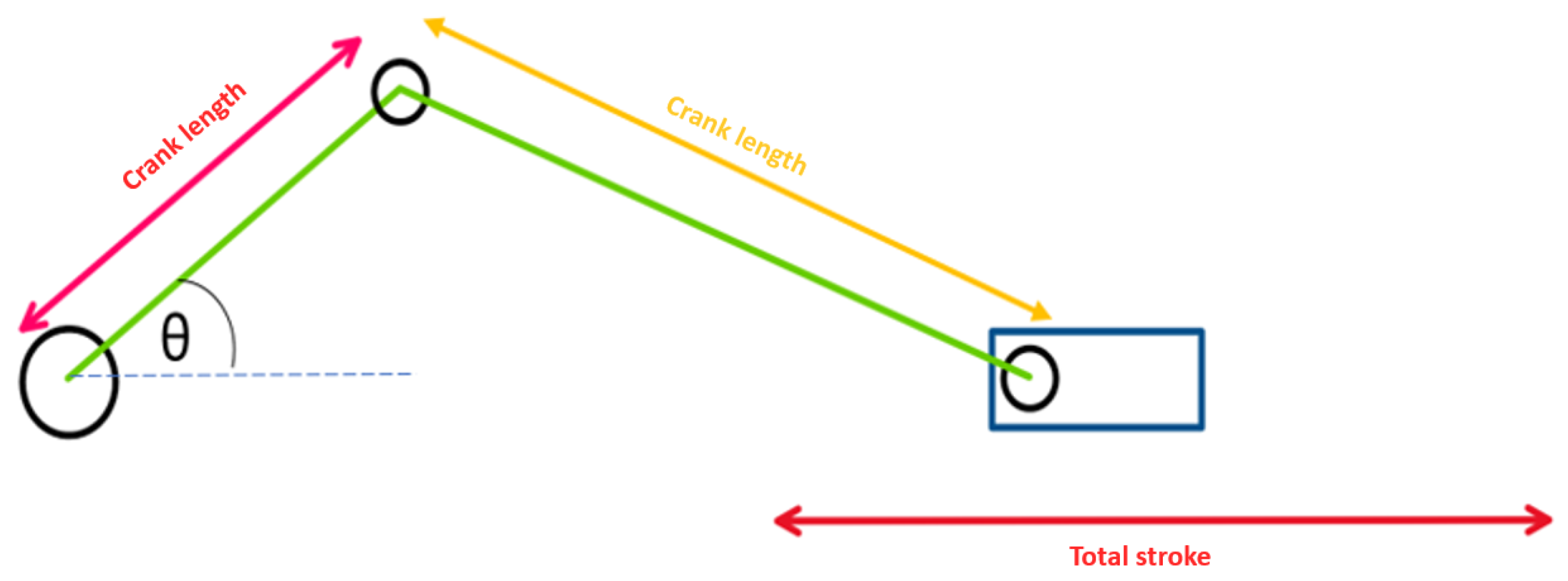
For designing this mechanism, the diagram in
Figure 29 will be used. It clearly shows that the actual position of the prismatic joint in the mechanism will depend greatly on the angle of the first rotational joint.
In this case, the mechanism is designed so that its total stroke length is 19 cm. If the crank is considered as the only link pushing the prismatic joint, then the initial position is considered from the angle’s maximum value, and the final position when the angle is at 0. Thus, the movement of the prismatic joint can be described with the following expression:
Where:
x: position of the prismatic joint
: Length of the crank
: angle of the first prismatic joint
From this relationship, it is deduced that the total stroke length of the prismatic joint will be the difference between the position where the angle takes a value of 0 and when it takes a value of 180 degrees:
Evaluating these data, we have:
As observed, the total stroke length will be twice the length of the crank. Since the total stroke length needed is 19 cm, the length of the crank can be calculated:
For the length of the connecting rod, the relationship in crank-slider mechanisms states that the ratio between the length of the connecting rod and the crank must be greater than 1:
However, due to the length of the total stroke, a value of 2 is defined to avoid interferences:
The complete design of the linear actuator, considering all measurements and a linear bearing to facilitate the movement of the prismatic joint, is shown in
Figure 30.
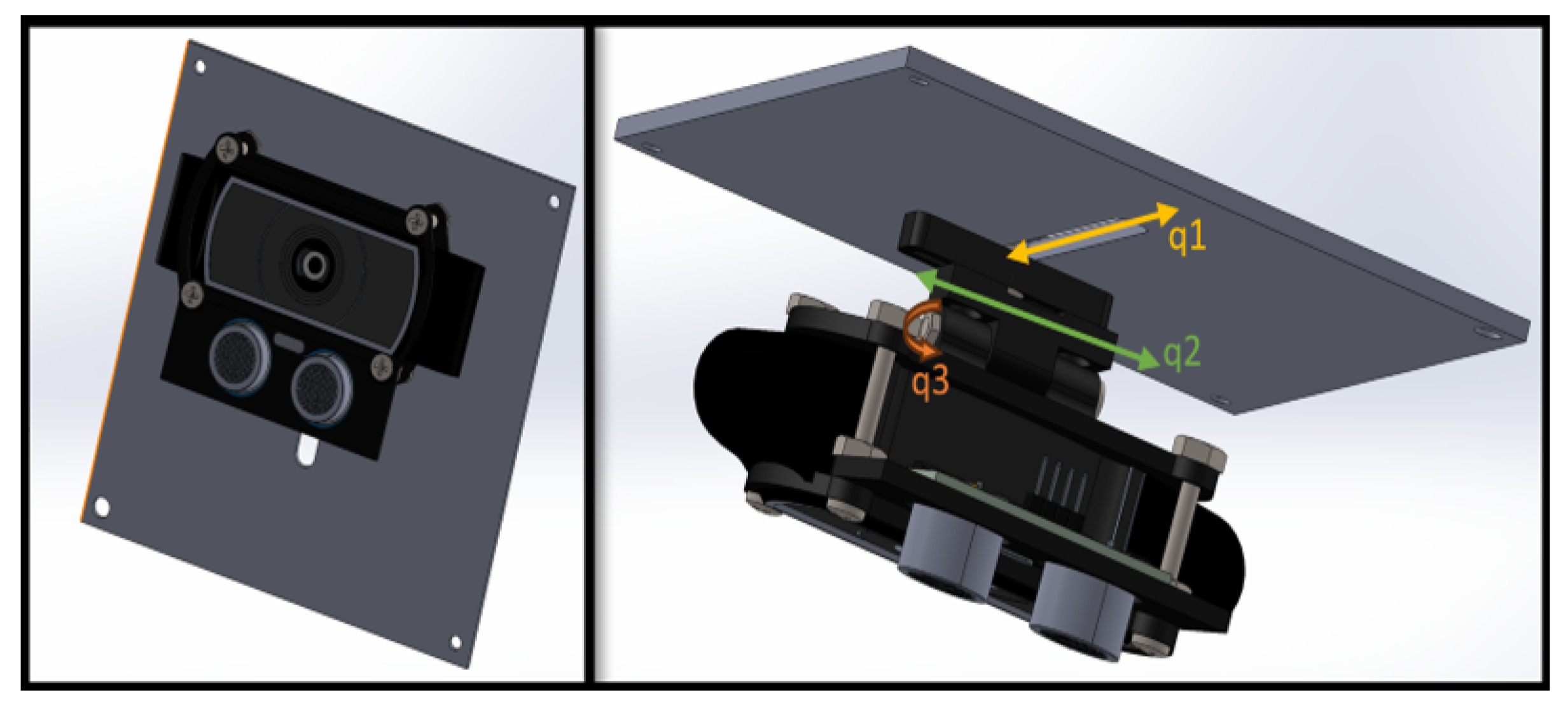
This structure is bolted directly to the body of the belt perpendicularly, located right in the center of the entire belt, where a station for inspecting all critical quality aspects will be placed. This station must have controlled lighting because the slightest alteration of light in the environment could lead to erroneous measurements. For this reason, a Logitech C920 webcam, which has a 1080p resolution and 78° field of view, will be used. This camera will be placed at the top middle of the belt to analyze the length and width dimensions of the pieces or boxes that pass through. Additionally, an HCSR04 ultrasonic sensor will be placed next to the camera to measure the height of the boxes. Thus, it was necessary to design a 3D-printed support that holds the camera and the ultrasonic sensor. This support will have three degrees of freedom, as shown in
Figure 31, to allow them to be moved and rotated as required.
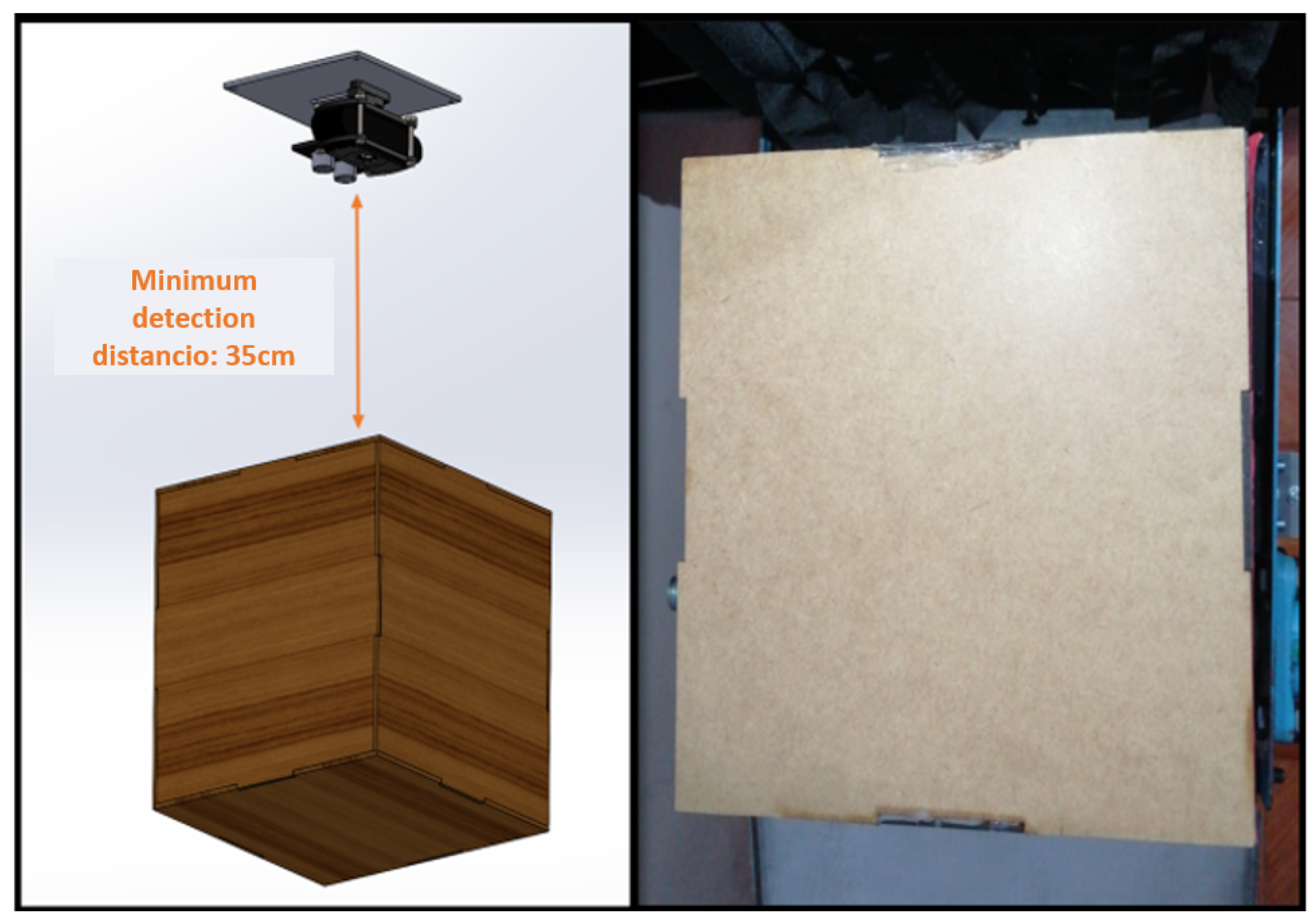
Another important design factor will be to detect the minimum distance at which the camera should be placed relative to a 20x20x20 cm test box so that it detects the entire top part, i.e., for the box to be within the field of view. Some tests were conducted, and it was determined that the camera should be at a minimum distance of 35 cm for this to happen.
Figure 32 shows an image of the camera detection at this distance.
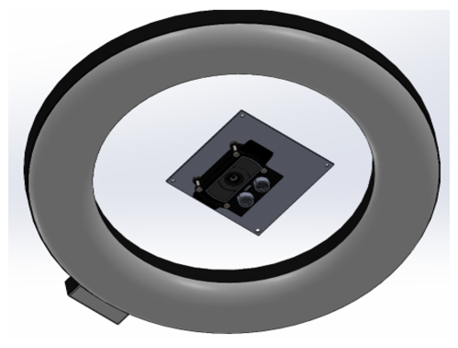
Based on this measure, a closed station is designed to darken the area where the pieces or boxes will pass through, so that with a 20 cm diameter ring light, adequate illumination can be controlled for the entire measurement process to be carried out without errors. This ring light will be placed concentrically to the webcam as shown in
Figure 33.
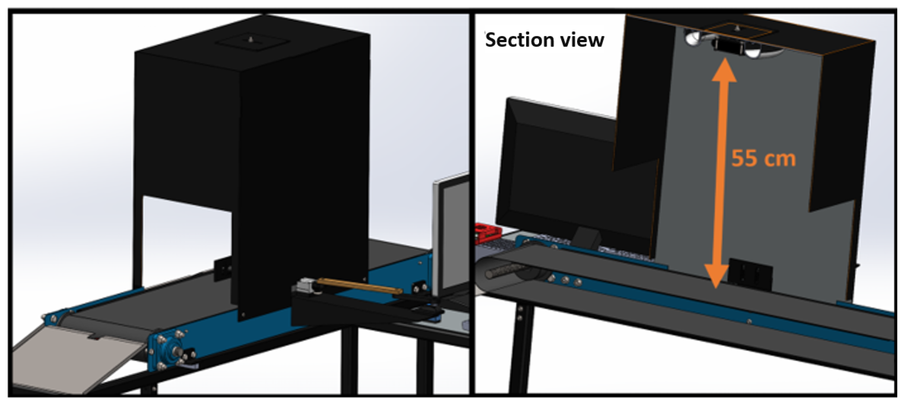
Since the boxes to be analyzed will have a maximum height of 20 cm, it is necessary to consider that from the belt, the camera should be at a distance of 55 cm. With this measure, the station that will help isolate and control external light is constructed. This station will be a box that covers the belt part enough to analyze the pieces and boxes, with the previously mentioned height.
Figure 34 shows the design it will have.
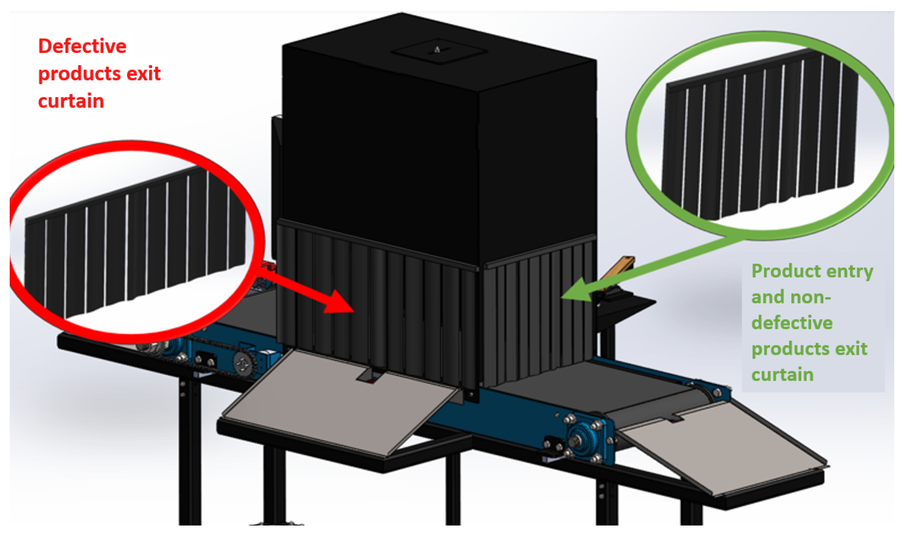
To ensure that no excess external light enters, curtains will be installed at the entrances and exits of this inspection station. The curtains for product entry and non-defective product exit will have the same length, 24x27 cm, and will be made of black fabric. In contrast, the curtain for defective product exit will have a larger range to ensure there are no collisions when the linear actuator pushes the boxes or pieces onto the tray. This curtain will have the same height of 24 cm but a width of 47 cm, also made of black fabric. Black color is special because it darkens the interior of the station by absorbing all visible light wavelengths, ensuring a controlled light environment inside the station.
Figure 35 shows the design with the curtains already installed.
With all these considerations, the mechanical and physical design of the entire project is completed.
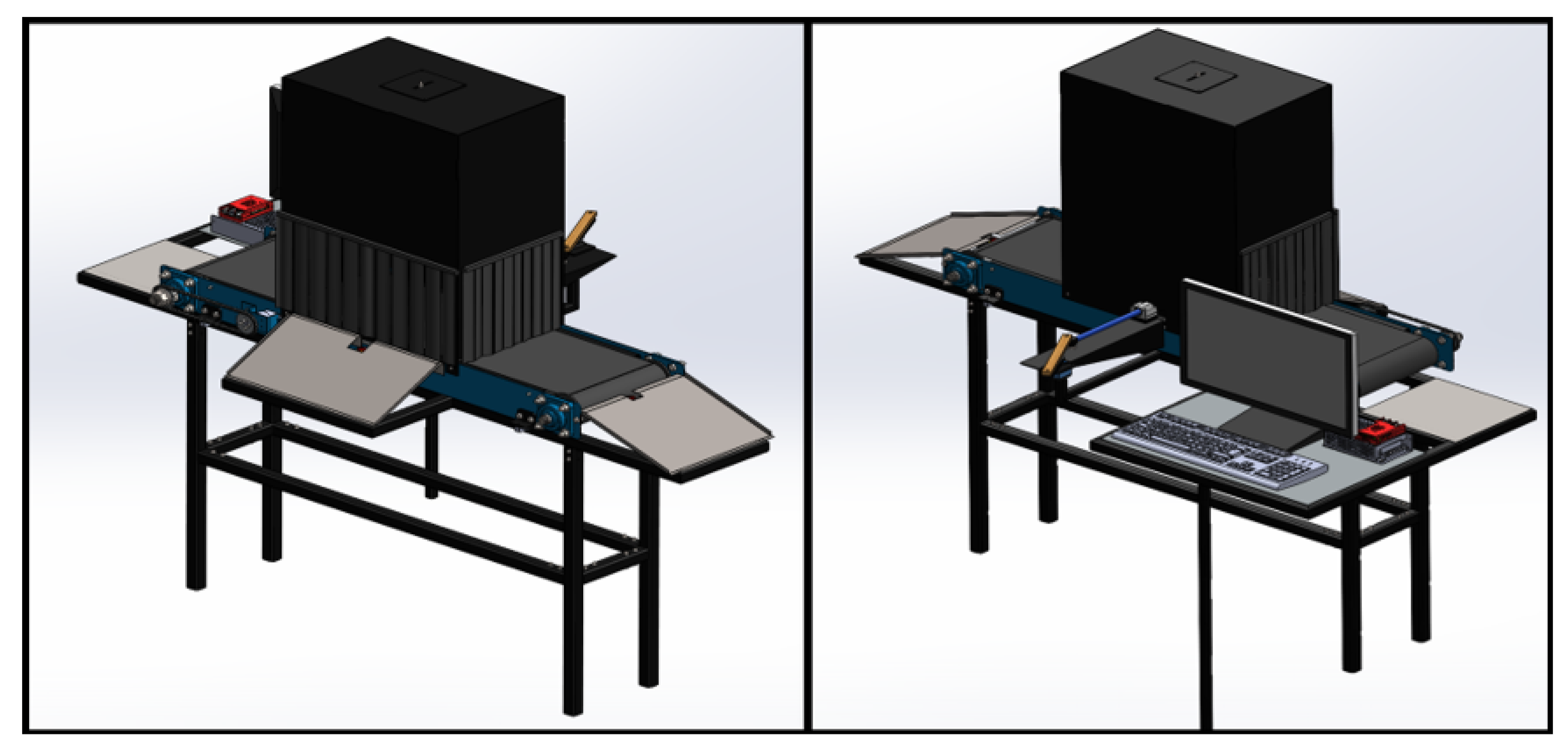
Figure 36 shows the complete design from both sides.
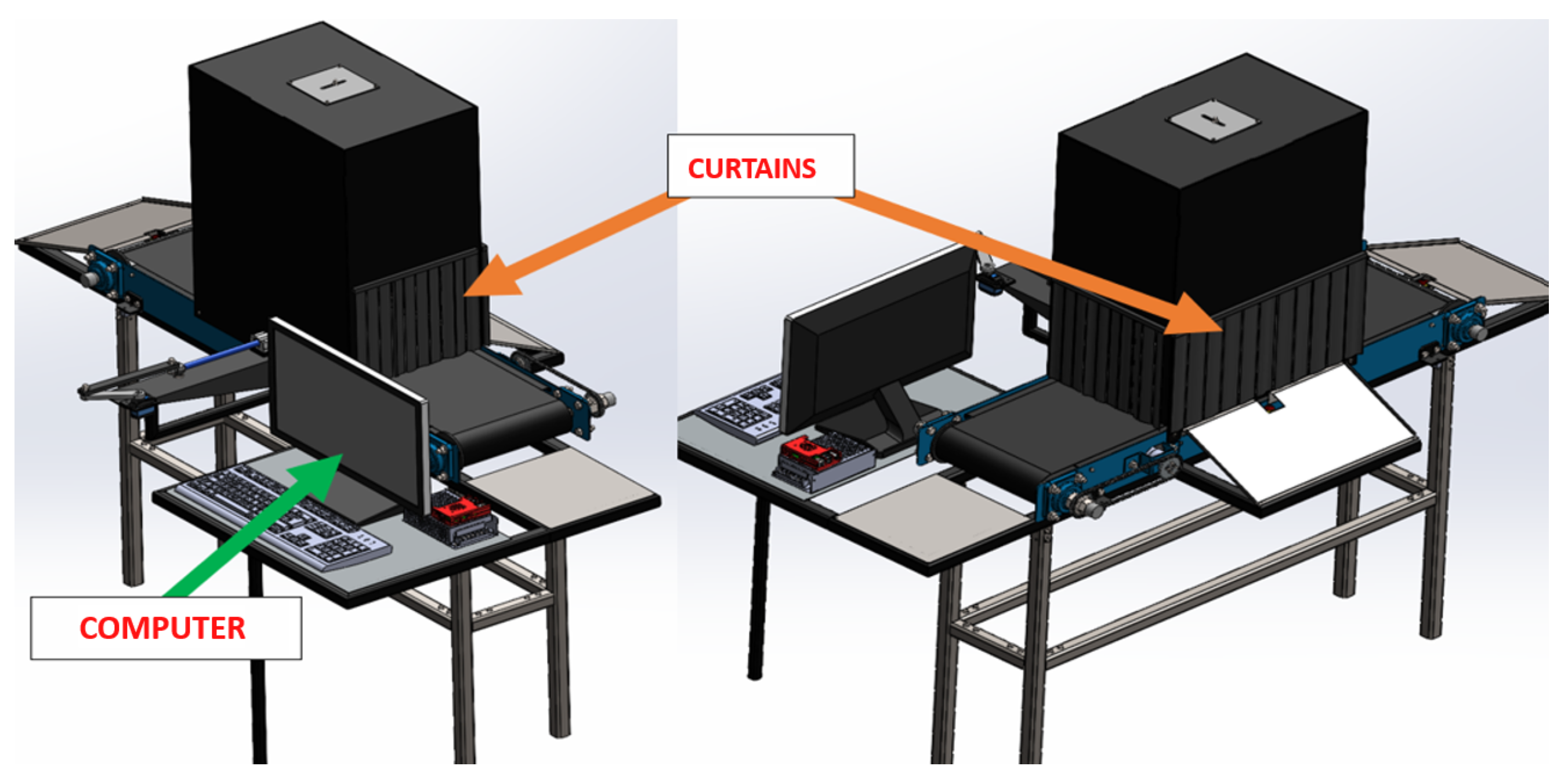
The results of the machine design can be seen in
Figure 37.
4. Conclusions
The adoption of technologies such as augmented reality, deep learning, and computer vision systems is crucial for transforming quality control in various industrial sectors. These technologies enable more precise and efficient supervision, adapting to modern and highly automated production environments. The reviewed case studies show that Quality 4.0 is being successfully implemented in various industries, from manufacturing to agriculture. The flexibility and adaptability of these technologies are essential to meet the challenges of a competitive and constantly changing market.
The proposed system, which uses artificial intelligence to inspect the dimensions, color, weight, and labeling of MDF boxes, demonstrates an effective integration of sensors and high-definition cameras. The tests conducted validate its capability to improve the accuracy and efficiency of inspections compared to manual methods.
Validation tests showed that the quality control system reduced inspection time by 50% compared to manual inspections. This reduction in inspection time allows for greater productivity and a significant decrease in operational costs. The accuracy in detecting dimensional defects increased by 95%, while the correct identification of colors and labeling achieved a 98% accuracy. These results indicate a considerable improvement in the final product quality, reducing the rate of defective products and enhancing customer satisfaction.
The implementation of the automated system reduced human errors by 85%. This decrease in human errors not only improves product quality but also increases the safety of the inspection process. The adoption of the automated quality control system resulted in a 30% reduction in operational costs, mainly due to the reduction in inspection time and the decrease in defective products. These cost savings can be reinvested in other production areas, improving the overall efficiency of the plant.
Figure 1.
Project scope diagram.
Figure 1.
Project scope diagram.
Figure 3.
Workspace division.
Figure 3.
Workspace division.
Figure 4.
Mechanical Subsystem.
Figure 4.
Mechanical Subsystem.
Figure 5.
Electronic Subsystem.
Figure 5.
Electronic Subsystem.
Figure 6.
Control Subsystem.
Figure 6.
Control Subsystem.
Figure 7.
Critical quality aspects of a piece.
Figure 7.
Critical quality aspects of a piece.
Figure 8.
Critical quality aspects of a box.
Figure 8.
Critical quality aspects of a box.
Figure 9.
Solution diagram for the mechanical subsystem.
Figure 9.
Solution diagram for the mechanical subsystem.
Figure 10.
Maximum dimensions of the box to be inspected.
Figure 10.
Maximum dimensions of the box to be inspected.
Figure 11.
Dimension relationship between the box and the conveyor belt.
Figure 11.
Dimension relationship between the box and the conveyor belt.
Figure 12.
Roller construction for the conveyor belt.
Figure 12.
Roller construction for the conveyor belt.
Figure 13.
Weight of the conveyor belt and rollers.
Figure 13.
Weight of the conveyor belt and rollers.
Figure 14.
Power transmission system.
Figure 14.
Power transmission system.
Figure 15.
Tensioning the conveyor belt.
Figure 15.
Tensioning the conveyor belt.
Figure 16.
Side face 1 of the metal structure.
Figure 16.
Side face 1 of the metal structure.
Figure 17.
Geared motor mount.
Figure 17.
Geared motor mount.
Figure 18.
Chain tensioning and sliding slots.
Figure 18.
Chain tensioning and sliding slots.
Figure 19.
Conveyor belt sagging due to weight.
Figure 19.
Conveyor belt sagging due to weight.
Figure 20.
Plate to support the belt and prevent sagging.
Figure 20.
Plate to support the belt and prevent sagging.
Figure 21.
Placement of load cells in the metal structure of the conveyor belt.
Figure 21.
Placement of load cells in the metal structure of the conveyor belt.
Figure 22.
Placement of load cells in the tubular structure.
Figure 22.
Placement of load cells in the tubular structure.
Figure 23.
Assembly of the tubular structure.
Figure 23.
Assembly of the tubular structure.
Figure 24.
Load application and fixation for simulation.
Figure 24.
Load application and fixation for simulation.
Figure 25.
Von Mises stresses.
Figure 25.
Von Mises stresses.
Figure 26.
Safety factor.
Figure 26.
Safety factor.
Figure 27.
Placement of output trays.
Figure 27.
Placement of output trays.
Figure 28.
Linear actuator stroke length.
Figure 28.
Linear actuator stroke length.
Figure 29.
Crank-slider mechanism diagram.
Figure 29.
Crank-slider mechanism diagram.
Figure 30.
Designed linear actuator.
Figure 30.
Designed linear actuator.
Figure 31.
Camera mount with 3 degrees of freedom.
Figure 31.
Camera mount with 3 degrees of freedom.
Figure 32.
Minimum detection distance for the entire box.
Figure 32.
Minimum detection distance for the entire box.
Figure 33.
Ring light concentric to the camera axis.
Figure 33.
Ring light concentric to the camera axis.
Figure 34.
Inspection station design with minimum height.
Figure 34.
Inspection station design with minimum height.
Figure 35.
Curtains for light control.
Figure 35.
Curtains for light control.
Figure 36.
Complete Mechanical Design.
Figure 36.
Complete Mechanical Design.
Figure 37.
Finished 3D Assembly.
Figure 37.
Finished 3D Assembly.
Table 1.
Specifications of the finished boxes.
Table 1.
Specifications of the finished boxes.
| - |
Length [cm] |
Width [cm] |
Height [cm] |
Color |
Weight [kg] |
Labeling |
| Box 1 |
15.00 ± 1.00 |
15.00 ± 1.00 |
15.00 ± 1.00 |
Red |
0.3 ± 0.2 |
5x5 [cm] label |
| Box 2 |
20.00 ± 1.00 |
20.00 ± 1.00 |
20.00 ± 1.00 |
Red |
0.6 ± 0.2 |
5x5 [cm] label |
Table 2.
Specifications of the finished pieces.
Table 2.
Specifications of the finished pieces.
| - |
Height [cm] |
Width [cm] |
Length [cm] |
Color |
| Piece 1 |
15.00 ± 1.00 |
15.00 ± 1.00 |
15.00 ± 1.00 |
Red |
| Piece 2 |
20.00 ± 1.00 |
20.00 ± 1.00 |
20.00 ± 1.00 |
Red |
Table 3.
Specifications of the finished boxes.
Table 3.
Specifications of the finished boxes.
| |
|
AC Motor |
Stepper Motor |
DC Motor |
| Criteria |
Weight |
Score |
Eval. |
Score |
Eval. |
Score |
Eval. |
| Transport speed |
25.00% |
5 |
1.25 |
4 |
1 |
4 |
1 |
| Cost |
25.00% |
3 |
0.75 |
4 |
1 |
5 |
1.25 |
| Adaptability to boxes and pieces |
20.00% |
5 |
1 |
5 |
1 |
5 |
1 |
| Easy implementation |
15.00% |
2 |
0.3 |
5 |
0.75 |
5 |
0.75 |
| Easy maintenance |
15.00% |
5 |
0.75 |
5 |
0.75 |
5 |
0.75 |
| |
Total points |
4.05 |
0 |
4.5 |
0 |
4.75 |
0 |
| |
Rank |
3 |
0 |
2 |
0 |
1 |
0 |
| |
Continue? |
No |
0 |
No |
0 |
Yes |
0 |
Table 4.
Specifications of the finished boxes.
Table 4.
Specifications of the finished boxes.
| Workstation |
Critical Quality Aspects |
| Laser Cutting |
1. Length [cm] |
| |
2. Width [cm] |
| Painting |
1. Length [cm] |
| |
2. Width [cm] |
| |
3. Color |
| Labeling |
1. Length [cm] |
| |
2. Width [cm] |
| |
3. Height [cm] |
| |
4. Color |
| |
5. Weight [kg] |
| |
6. Labeling |
Table 5.
Technical specifications of the motor.
Table 5.
Technical specifications of the motor.
| Parameter |
Value |
| Voltage |
12 [V] |
| Current with load |
5.5 [A] |
| No-load current |
0.2 [A] |
| Gear ratio |
100:1 |
| No-load speed |
100 [RPM] |
| Torque |
34
|
| Maximum power |
8 [W] |
