Submitted:
01 June 2024
Posted:
05 June 2024
You are already at the latest version
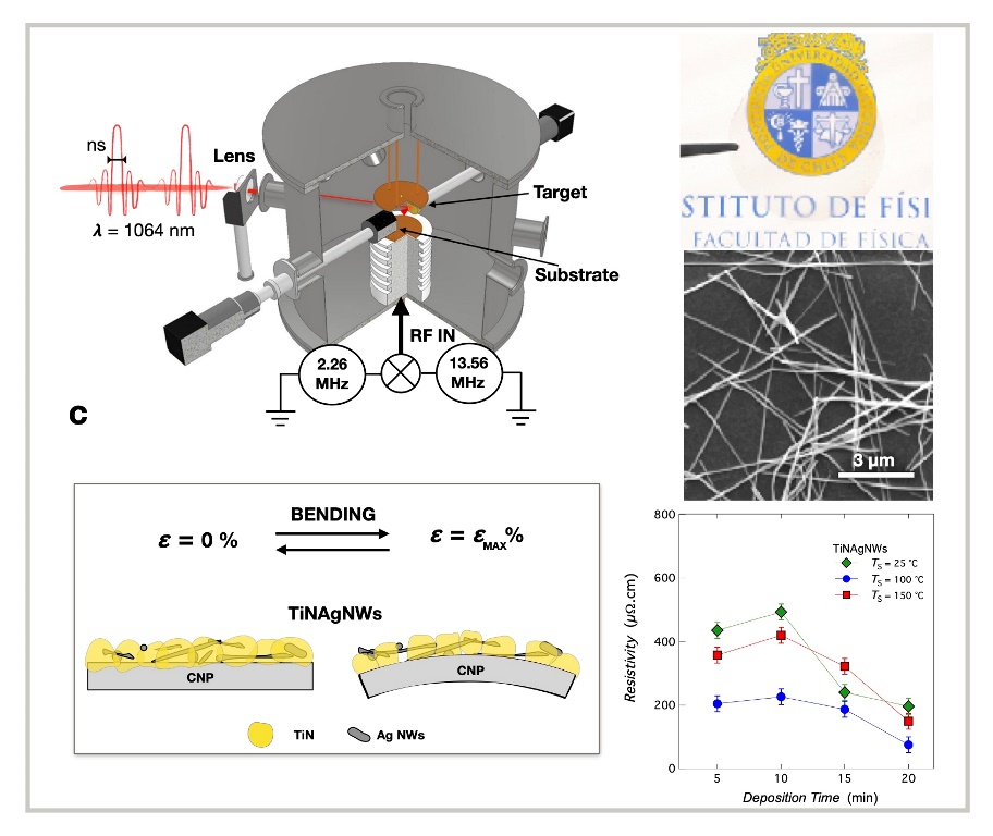
Abstract
Keywords:
1. Introduction
2. Materials and Methods
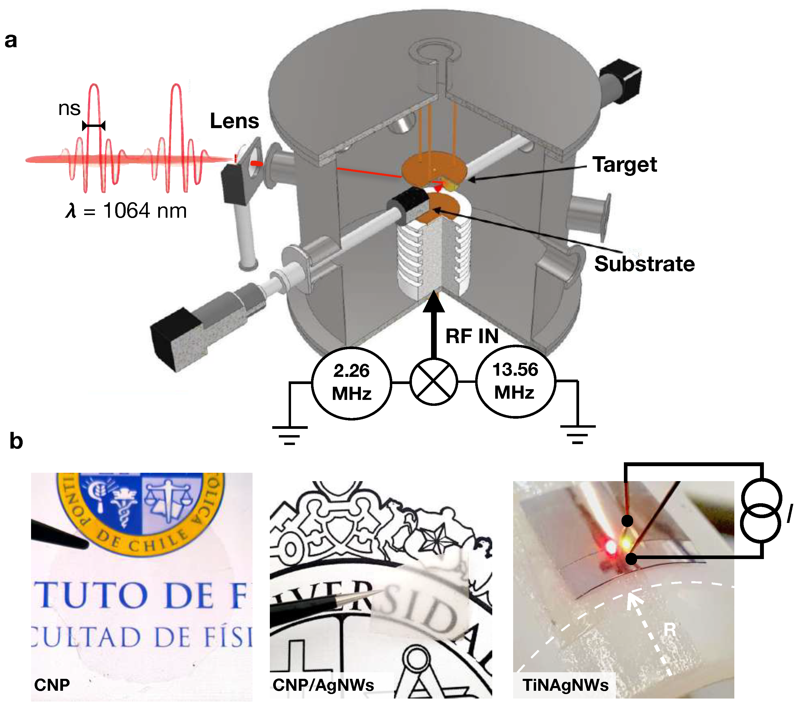
2.1. Plasma-Enhanced Pulsed Laser Deposition
2.2. Nanocomposite Electrode Fabrication
2.3. CNP Synthesis
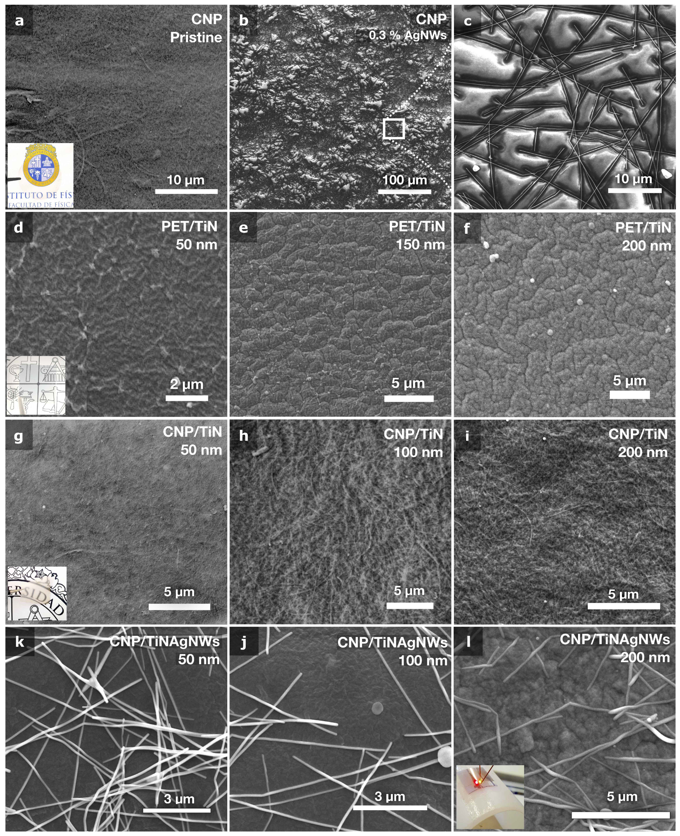
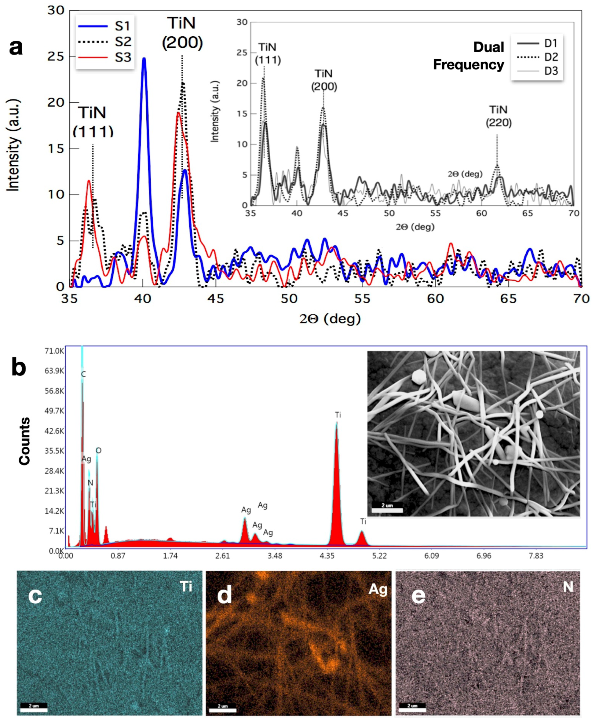
2.4. Characterization
3. Results and Discussion
3.1. Coating Microstructure Characterization
4. Conclusions
Supplementary Materials
Author Contributions
Funding
Data Availability Statement
Acknowledgments
Conflicts of Interest
Abbreviations
| TCE | transparent conductive electrode |
| PE-PLD | plasma-enhanced pulsed laser deposition |
| TiN | titanium nitride |
| CNP | Cellulose nanopaper |
| AGNWs | Silver Nanowires |
| PET | Polyethylene terephthalate |
| 2f-CCP | to a dual-frequency capacitively coupled plasma |
References
- Hsieh, M.C.; Koga, H.; Suganuma, K.; Nogi, M. Hazy Transparent Cellulose Nanopaper. Scientific Reports 2017, 7, 41590. [Google Scholar] [CrossRef] [PubMed]
- Mashkour, M.; Sharifinia, M.; Yousefi, H.; Afra, E. MWCNT-coated cellulose nanopapers: Droplet-coating, process factors, and electrical conductivity performance. Carbohydrate Polymers 2018, 202, 504–512. [Google Scholar] [CrossRef] [PubMed]
- Lian, Y.; Yu, H.; Wang, M.; Yang, X.; Zhang, H. Ultrasensitive Wearable Pressure Sensors Based on Silver Nanowire-Coated Fabrics. Nanoscale Research Letters 2020, 15, 70. [Google Scholar] [CrossRef]
- Jiao, K.; Cao, W.; Yuan, W.; Yuan, H.; Zhu, J.; Gao, X.; Duan, S.; Yong, R.; Zhao, Z.; Song, P.; et al. Cellulose Nanostructures as Tunable Substrates for Nanocellulose-Metal Hybrid Flexible Composites. ChemPlusChem 2024, n/a, e202300704. [Google Scholar] [CrossRef] [PubMed]
- Du, X.; Zhang, Z.; Liu, W.; Deng, Y. Nanocellulose-based conductive materials and their emerging applications in energy devices - A review. Nano Energy 2017, 35, 299–320. [Google Scholar] [CrossRef]
- Wang, Z.; Pan, R.; Sun, R.; Edström, K.; Strømme, M.; Nyholm, L. Nanocellulose Structured Paper-Based Lithium Metal Batteries. ACS Applied Energy Materials 2018, 1, 4341–4350. [Google Scholar] [CrossRef]
- Han, L.; Cui, S.; Yu, H.Y.; Song, M.; Zhang, H.; Grishkewich, N.; Huang, C.; Kim, D.; Tam, K.M.C. Self-Healable Conductive Nanocellulose Nanocomposites for Biocompatible Electronic Skin Sensor Systems. ACS Applied Materials & Interfaces 2019, 11, 44642–44651. [Google Scholar] [CrossRef] [PubMed]
- Xu, H.; Xie, Y.; Zhu, E.; Liu, Y.; Shi, Z.; Xiong, C.; Yang, Q. Supertough and ultrasensitive flexible electronic skin based on nanocellulose/sulfonated carbon nanotube hydrogel films. J. Mater. Chem. A 2020, 8, 6311–6318. [Google Scholar] [CrossRef]
- Ren, N.; Ai, Y.; Yue, N.; Cui, M.; Huang, R.; Qi, W.; Su, R. Shear-Induced Fabrication of Cellulose Nanofibril/Liquid Metal Nanocomposite Films for Flexible Electromagnetic Interference Shielding and Thermal Management. ACS Applied Materials and Interfaces 2024. [Google Scholar] [CrossRef]
- Azani, M.R.; Hassanpour, A.; Torres, T. Benefits, Problems, and Solutions of Silver Nanowire Transparent Conductive Electrodes in Indium Tin Oxide (ITO)-Free Flexible Solar Cells. Advanced Energy Materials 2020, 10, 2002536. [Google Scholar] [CrossRef]
- Nogi, M.; Karakawa, M.; Komoda, N.; Yagyu, H.; Nge, T.T. Transparent Conductive Nanofiber Paper for Foldable Solar Cells. Scientific Reports 2015, 5, 17254. [Google Scholar] [CrossRef] [PubMed]
- Lee, D.G.; Lee, D.; Yoo, J.S.; Lee, S.; Jung, H.S. Effective passivation of Ag nanowire-based flexible transparent conducting electrode by TiO2 nanoshell. Nano Convergence 2016, 3, 20. [Google Scholar] [CrossRef] [PubMed]
- Lee, S.; Song, Y.; Ko, Y.; Ko, Y.; Ko, J.; Kwon, C.H.; Huh, J.; Kim, S.W.; Yeom, B.; Cho, J. A Metal-Like Conductive Elastomer with a Hierarchical Wrinkled Structure. Advanced Materials 2020, 32, 1906460. [Google Scholar] [CrossRef] [PubMed]
- Nikravesh, S.; Ryu, D.; Shen, Y.L. Instabilities of Thin Films on a Compliant Substrate: Direct Numerical Simulations from Surface Wrinkling to Global Buckling. Scientific Reports 2020, 10, 5728. [Google Scholar] [CrossRef] [PubMed]
- Zander, Z.K.; Becker, M.L. Antimicrobial and Antifouling Strategies for Polymeric Medical Devices. ACS Macro Letters 2018, 7, 16–25. [Google Scholar] [CrossRef] [PubMed]
- Song, B.; Zhang, E.; Han, X.; Zhu, H.; Shi, Y.; Cao, Z. Engineering and Application Perspectives on Designing an Antimicrobial Surface. ACS Applied Materials & Interfaces 2020, 12, 21330–21341. [Google Scholar]
- Helmlinger, J.; Sengstock, C.; Groß-Heitfeld, C.; Mayer, C.; Schildhauer, T.A.; Köller, M.; Epple, M. Silver nanoparticles with different size and shape: equal cytotoxicity, but different antibacterial effects. RSC Adv. 2016, 6, 18490–18501. [Google Scholar] [CrossRef]
- Calderon Velasco, S.; Cavaleiro, A.; Carvalho, S. Functional properties of ceramic-Ag nanocomposite coatings produced by magnetron sputtering. Progress in Materials Science 2016, 84, 158–191. [Google Scholar] [CrossRef]
- Zhang, Z.; Wu, Y.; Wang, Z.; Zhang, X.; Zhao, Y.; Sun, L. Electrospinning of Ag Nanowires/polyvinyl alcohol hybrid nanofibers for their antibacterial properties. Materials Science and Engineering: C 2017, 78, 706–714. [Google Scholar] [CrossRef]
- Valentin, E.; Bottomley, A.L.; Chilambi, G.S.; Harry, E.J.; Amal, R.; Sotiriou, G.A.; Rice, S.A.; Gunawan, C. Heritable nanosilver resistance in priority pathogen: a unique genetic adaptation and comparison with ionic silver and antibiotics. Nanoscale 2020, 12, 2384–2392. [Google Scholar] [CrossRef]
- Guler, U.; Boltasseva, A.; Shalaev, V.M. Refractory Plasmonics. Science 2014, 344, 263–264. [Google Scholar] [CrossRef] [PubMed]
- Hyde, G.K.; McCullen, S.D.; Jeon, S.; Stewart, S.M.; Jeon, H.; Loboa, E.G.; Parsons, G.N. Atomic layer deposition and biocompatibility of titanium nitride nano-coatings on cellulose fiber substrates. Biomedical Materials 2009, 4, 025001. [Google Scholar] [CrossRef] [PubMed]
- Wu, W.Y.; Chan, M.Y.; Hsu, Y.H.; Chen, G.Z.; Liao, S.C.; Lee, C.H.; Lui, P.W. Bioapplication of TiN thin films deposited using high power impulse magnetron sputtering. Surface and Coatings Technology 2019, 362, 167–175. [Google Scholar] [CrossRef]
- Zhang, L.; Yang, H.; Pang, X.; Gao, K.; Volinsky, A.A. Microstructure, residual stress, and fracture of sputtered TiN films. Surface and Coatings Technology 2013, 224, 120–125. [Google Scholar] [CrossRef]
- Luo, Q.; Yang, S.; Cooke, K. Hybrid HIPIMS and DC magnetron sputtering deposition of TiN coatings: Deposition rate, structure and tribological properties. Surface and Coatings Technology 2013, 236, 13–21. [Google Scholar] [CrossRef]
- Lima, L.; Diniz, J.; Doi, I.; Fo, J.G. Titanium nitride as electrode for MOS technology and Schottky diode: Alternative extraction method of titanium nitride work function. Microelectronic Engineering 2012, 92, 86–90. [Google Scholar] [CrossRef]
- Torgovkin, A.; Chaudhuri, S.; Ruhtinas, A.; Lahtinen, M.; Sajavaara, T.; Maasilta, I.J. High quality superconducting titanium nitride thin film growth using infrared pulsed laser deposition. Superconductor Science and Technology 2018, 31, 055017. [Google Scholar] [CrossRef]
- Adamovich, V.; Shoustikov, A.; Thompson, M.E. TiN as an Anode Material for Organic Light-Emitting Diodes. Advanced Materials 1999, 11, 727–730. [Google Scholar] [CrossRef]
- Briggs, J.A.; Naik, G.V.; Petach, T.A.; Baum, B.K.; Goldhaber-Gordon, D.; Dionne, J.A. Fully CMOS-compatible titanium nitride nanoantennas. Applied Physics Letters 2016, 108, 051110. [Google Scholar] [CrossRef]
- von Seefeld, H.; Cheung, N.W.; Maenpaa, M.; Nicolet, M. . Investigation of titanium nitride layers for solar-cell contacts. IEEE Transactions on Electron Devices 1980, 27, 873–876. [Google Scholar] [CrossRef]
- Shi, W.; Zheng, H.; Zhao, Y.; Pu, X.; Shui, X.; Lin, Y.; Chen, G.; Yang, X.; Zhang, G.; Wei, B. Highly Efficient Red, Green, and Blue Inverted Top-Emitting Organic Light-Emitting Diodes with Microstructured TiN Substrate. physica status solidi (RRL) – Rapid Research Letters [https://onlinelibrary.wiley.com/doi/pdf/ 10.1002/pssr.202400032]. n/a, 2400032. [CrossRef]
- Sugavaneshwar, R.P.; Ishii, S.; Dao, T.D.; Ohi, A.; Nabatame, T.; Nagao, T. Fabrication of Highly Metallic TiN Films by Pulsed Laser Deposition Method for Plasmonic Applications. ACS Photonics 2018, 5, 814–819. [Google Scholar] [CrossRef]
- Chang, C.C.; Nogan, J.; Yang, Z.P.; Kort-Kamp, W.J.M.; Ross, W.; Luk, T.S.; Dalvit, D.A.R.; Azad, A.K.; Chen, H.T. Highly Plasmonic Titanium Nitride by Room-Temperature Sputtering. Scientific Reports 2019, 9, 15287. [Google Scholar] [CrossRef] [PubMed]
- Saikia, P.; Bhuyan, H.; Escalona, M.; Favre, M.; Wyndham, E.; Maze, J.; Schulze, J. Study of dual radio frequency capacitively coupled plasma: an analytical treatment matched to an experiment. Plasma Sources Science and Technology 2018, 27, 015014. [Google Scholar] [CrossRef]
- Escalona, M.; Bhuyan, H.; Ibacache, S.; Retamal, M.; Saikia, P.; Borgohain, C.; Valenzuela, J.; Veloso, F.; Favre, M.; Wyndham, E. Study of titanium nitride film growth by plasma enhanced pulsed laser deposition at different experimental conditions. Surface and Coatings Technology 2021, 405, 126492. [Google Scholar] [CrossRef]
- Cerda, E.; Mahadevan, L. Geometry and Physics of Wrinkling. Phys. Rev. Lett. 2003, 90, 074302. [Google Scholar] [CrossRef] [PubMed]
- Gence, L.; Escalona, M.; Castillo, C.; Quero, F.; Saikia, P.; Wheatley, R.; Diaz-Droguett, D.E.; Retamal, M.J.; Volkmann, U.G.; Bhuyan, H. Wrinkled titanium nitride nanocomposite for robust bendable electrodes. Nanotechnology 2019, 30, 495705. [Google Scholar] [CrossRef] [PubMed]
- Mei, H.; Huang, R.; Chung, J.Y.; Stafford, C.M.; Yu, H.H. Buckling modes of elastic thin films on elastic substrates. Applied Physics Letters 2007, 90, 151902. [Google Scholar] [CrossRef]
- Genzer, J.; Groenewold, J. Soft matter with hard skin: From skin wrinkles to templating and material characterization. Soft Matter 2006, 2, 310–323. [Google Scholar] [CrossRef]
- Wang, Y.; Li, Z.; Xiao, J. Stretchable Thin Film Materials: Fabrication, Application, and Mechanics. Journal of Electronic Packaging 2016, 138, 020801. [Google Scholar] [CrossRef]
- Waller, J.; Lalande, L.; Leterrier, Y.; Månson, J.A. Modelling the effect of temperature on crack onset strain of brittle coatings on polymer substrates. Thin Solid Films 2011, 519, 4249–4255. [Google Scholar] [CrossRef]
- Nasr Saleh, M.; Lubineau, G. Understanding the mechanisms that change the conductivity of damaged ITO-coated polymeric films: A micro-mechanical investigation. Solar Energy Materials and Solar Cells 2014, 130, 199–207. [Google Scholar] [CrossRef]
- Gadre, K.S.; Alford, T. Crack formation in TiN films deposited on Pa-n due to large thermal mismatch. Thin Solid Films 2001, 394, 124–129. [Google Scholar] [CrossRef]
- Chaiwong, C.; McKenzie, D.; Bilek, M. Cracking of titanium nitride films grown on polycarbonate. Surface and Coatings Technology 2007, 201, 5596–5600. [Google Scholar] [CrossRef]
- Guo, B.; Chen, W.; Yan, L. Preparation of Flexible, Highly Transparent, Cross-Linked Cellulose Thin Film with High Mechanical Strength and Low Coefficient of Thermal Expansion. ACS Sustainable Chemistry & Engineering 2013, 1, 1474–1479. [Google Scholar] [CrossRef]
- Nogi, M.; Iwamoto, S.; Nakagaito, A.N.; Yano, H. Optically Transparent Nanofiber Paper. Advanced Materials 2009, 21, 1595–1598. [Google Scholar] [CrossRef]
- Rencheck, M.L.; Weiss, A.J.; El Awad Azrak, S.M.; Forti, E.S.; Nuruddin, M.; Youngblood, J.P.; Davis, C.S. Nanocellulose Film Modulus Determination via Buckling Mechanics Approaches. ACS Applied Polymer Materials 2020, 2, 578–584, [https://doi.org/10.1021/acsapm.9b00969]. [Google Scholar] [CrossRef]
- Hirano, T.; Mitsuzawa, K.; Ishioka, S.; Daicho, K.; Soeta, H.; Zhao, M.; Takeda, M.; Takai, Y.; Fujisawa, S.; Saito, T. Anisotropic Thermal Expansion of Transparent Cellulose Nanopapers. Frontiers in Chemistry 2020, 8, 68. [Google Scholar] [CrossRef]
- Wakabayashi, M.; Fujisawa, S.; Saito, T.; Isogai, A. Nanocellulose Film Properties Tunable by Controlling Degree of Fibrillation of TEMPO-Oxidized Cellulose. Frontiers in Chemistry 2020, 8, 37. [Google Scholar] [CrossRef]
- Roy, M.; Mucha, N.R.; Ponnam, R.G.; Jaipan, P.; Scott-Emuakpor, O.; Yarmolenko, S.; Majumdar, A.K.; Kumar, D. Quantum interference effects in titanium nitride films at low temperatures. Thin Solid Films 2019, 681, 1–5. [Google Scholar] [CrossRef]
- Leterrier, Y.; Médico, L.; Demarco, F.; Månson, J.A.; Betz, U.; Escolà, M.; Kharrazi Olsson, M.; Atamny, F. Mechanical integrity of transparent conductive oxide films for flexible polymer-based displays. Thin Solid Films 2004, 460, 156–166. [Google Scholar] [CrossRef]
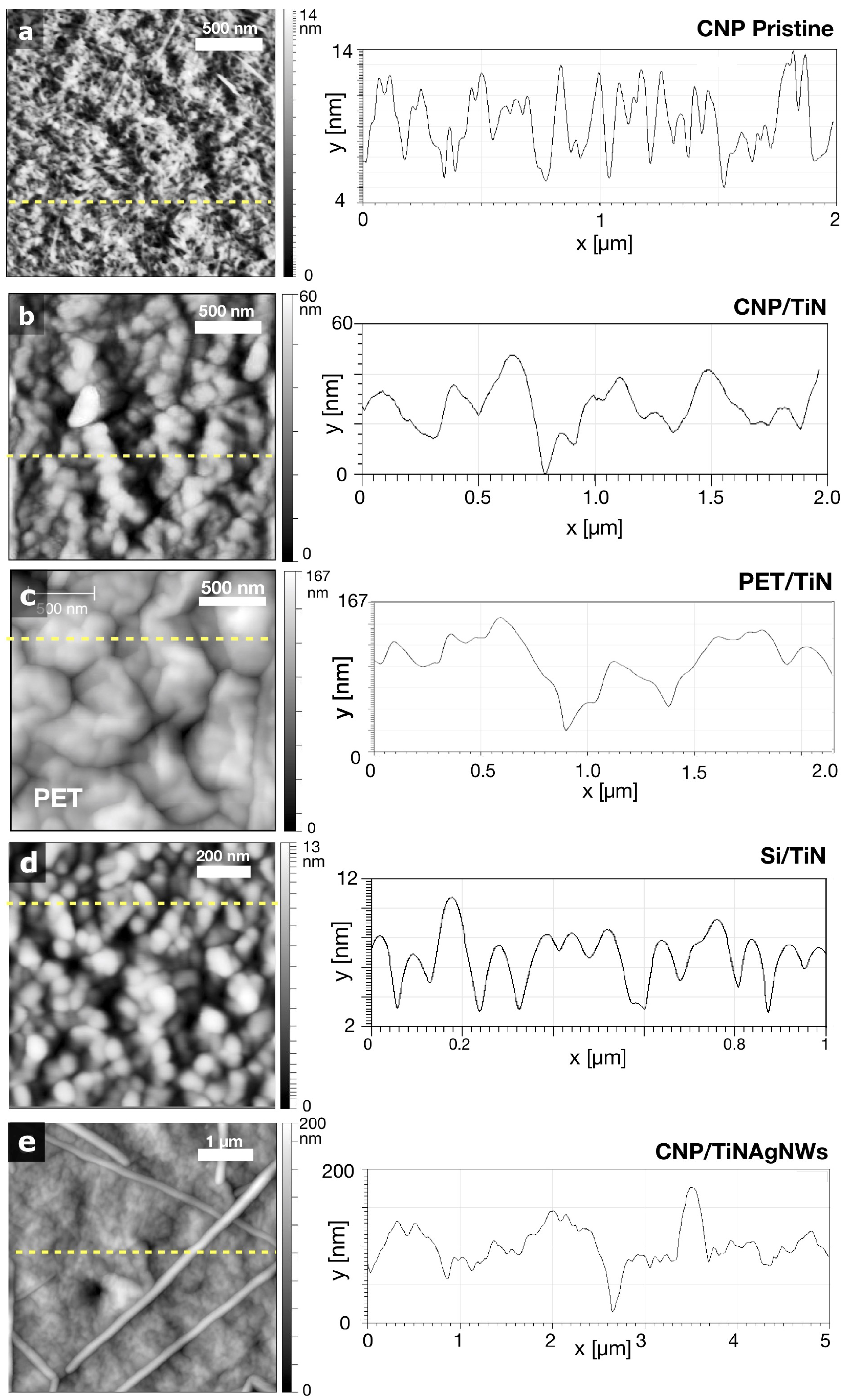
| Samples | TiN Thickness | ScanSize | ||
|---|---|---|---|---|
| (nm) | (nm) | (nm) | () | |
| CNP | - | 4.4 | 5.6 | 2x2 |
| TiN-100/PET | 100 | 20.5 | 25.6 | 2x2 |
| TiN-100/CNP | 100 | 5.9 | 7.6 | 2x2 |
| TiN-250/PET | 250 | 27.5 | 32.3 | 2x2 |
| TiN-250/CNP | 250 | 7.8 | 9.3 | 2x2 |
| TiNAgNW-100/CNP | 100 | 12.2 | 15.5 | 2x2 |
| TiNAgNW-250/CNP | 250 | 17.3 | 21.1 | 2x2 |
| Materials | Thickness | Poisson | CTE, | Young Modulus | References |
|---|---|---|---|---|---|
| (m) | Ratio | () | (GPa) | ||
| ITO | 0.100 | 0.15 | 10 | 1 | [41,42] |
| TiN | 0.25 | 6-9 | 400 | [43,44] | |
| PET | 75-180 | 0.35 | 35 | 3 | [37] |
| CNP | 50-100 | 0.23 | 7 | 1-8 | [45,46,47,48,49] |
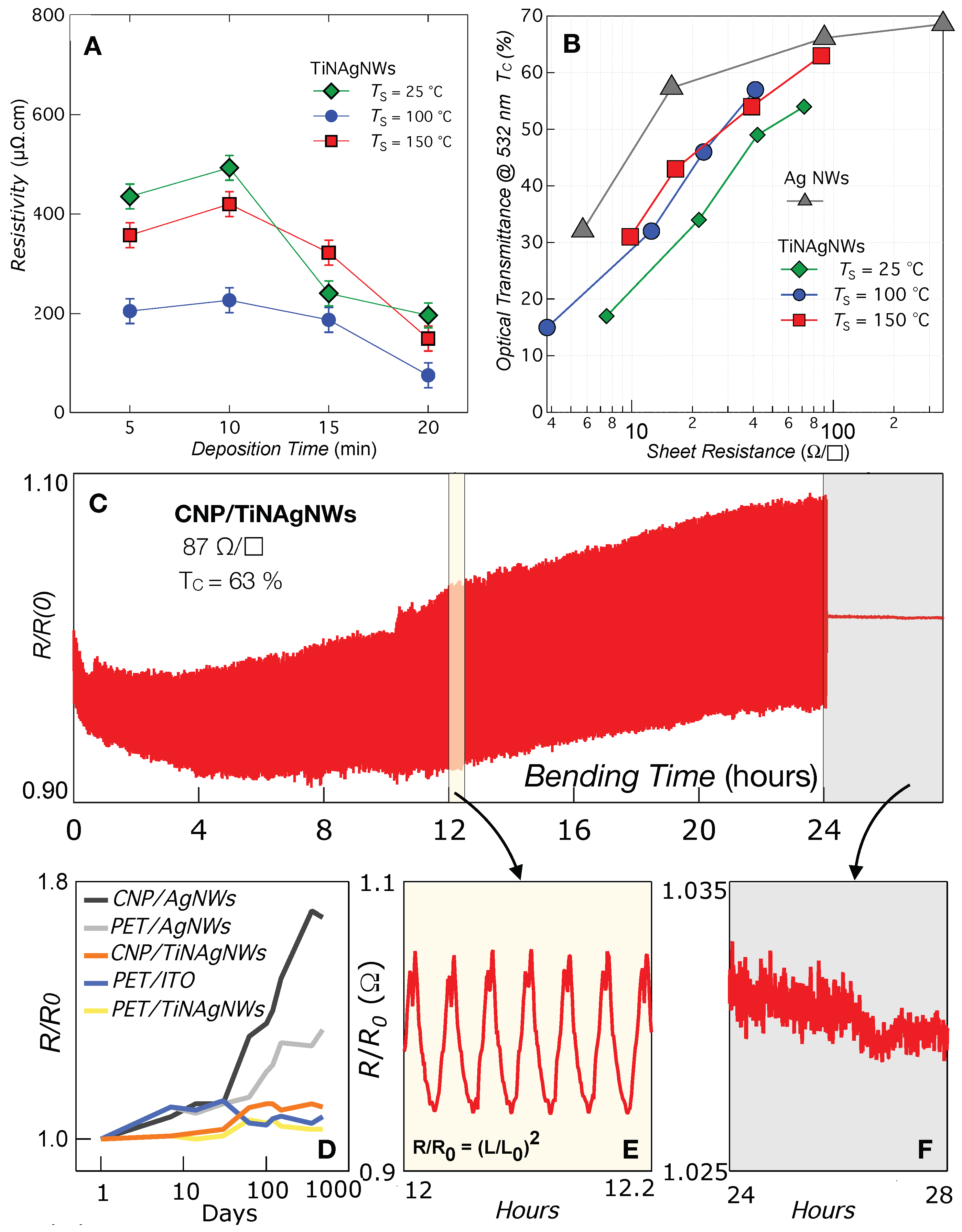
| Samples | ( | (% @ 532 nm) | (Strain =2%) |
| PET | - | 87 | - |
| PET/AgNW | 32 | 78 | 1.27 |
| PET/ITO | 60 | 78 | 29090 |
| CNP/AgNW | 32 | 76 | 1.22 |
| CNP/TiN | 104 | 49 | 3.93 |
| CNP/TiNAgNW | 21 | 43 | 1.07 |
| CNP/TiNAgNW | 13 | 32 | 1.18 |
| CNP/TiNAgNW | 87 | 63 | 1.45 |
Disclaimer/Publisher’s Note: The statements, opinions and data contained in all publications are solely those of the individual author(s) and contributor(s) and not of MDPI and/or the editor(s). MDPI and/or the editor(s) disclaim responsibility for any injury to people or property resulting from any ideas, methods, instructions or products referred to in the content. |
© 2024 by the authors. Licensee MDPI, Basel, Switzerland. This article is an open access article distributed under the terms and conditions of the Creative Commons Attribution (CC BY) license (http://creativecommons.org/licenses/by/4.0/).


