1. Introduction
Autonomous road lane detection and navigation systems are the key components in the development of self-driving vehicles. These systems can enhance the safety, efficiency, and reliability of autonomous driving by enabling vehicles to accurately detect and follow road lanes without human intervention. Traditional automobiles have a large negative influence on the environment, our roads are congested, and accidents happen frequently. To solve these problems and build a more sustainable and effective transportation system, creative solutions are required. There is optimism thanks to recent advancements in autonomous car technology. With the help of sophisticated AI algorithms and more sophisticated sensors, cars are becoming increasingly intelligent and capable of negotiating intricate road networks. These developments should lessen their negative effects on the environment, lessen traffic congestion, and reduce accidents. The vision of using artificial intelligence to build self-driving cars is the driving force behind our endeavor. The field of autonomous road lane detection and navigation systems has seen significant advancements in recent years, driven by the integration of various technologies such as computer vision, machine learning, and sensor fusion. The integration of artificial intelligence (AI) into autonomous road lane detection and navigation systems has revolutionized the field, enhancing the accuracy, reliability, and adaptability of these systems. The literature survey shows significant contributions and advancements in AI-based lane detection and navigation, emphasizing the evolution from traditional methods to contemporary AI-driven techniques.
Machine learning and pattern recognition approaches using Support Vector Machines (SVM) [
1] and artificial neural network [
2] were used for lane detection. Long, J etal [
3] proposed fully convolutional networks precise lane detection. Deep learning techniques such as convolutional neural networks for real-time lane following [
4] and semantic segmentation for lane detection with better accuracy [
5,
6] are reported. Bewley et al. [
7] presented a technique for simple lane detection and tracking for highway driving using image processing. Krauss [
8] presented autonomous vehicle platform by combining Raspberry Pi and Arduino microcontrollers for real-time vehicle control and navigation. Jain et al. [
9] introduced a self-driving car model based on convolutional neural networks (CNNs) implemented on Raspberry Pi and Arduino platforms. Real time implementation on lane detection using Image processing and raspberry pi is reported in [
10,
11].
Fast LIDAR-based road detection using fully convolutional neural networks [
12] and LiDAR and camera fusion approach for object distance estimation in autonomous vehicles [
13] are also reported using LIDAR and camera fusion. Hafeez et al. [
14] presented low-cost solutions for autonomous vehicles with affordable technologies and approaches to enable the widespread adoption of autonomous driving technology. Landman et al. [
15] investigated user interface design for autonomous vehicles aiming to improve user experience and safety [
15]. CNN is combined with RNN to incorporate temporal information from video frames, improving the consistency and stability of lane detection over time. [
16].
Deep insights into the latest advancements in deep learning techniques for lane detection, contributing to the development of more accurate and reliable autonomous driving systems are reported in [
17,
18]. Xu et al. [
19] proposed a high-speed lane detection method for autonomous vehicles. This literature on autonomous road lane Detection and navigation systems demonstrates significant advancements driven by deep learning, sensor fusion, and real-time processing capabilities. From foundational work with SVMs and early neural networks to sophisticated deep learning models and multimodal approaches, AI has significantly enhanced the accuracy and reliability of lane detection systems. These is still a scope on improving robustness and efficiency and achieving integration with fully autonomous driving systems. The development of autonomous vehicle prototypes has both challenges and opportunities for the transportation industry. With the rapid advancement of technology, particularly in artificial intelligence and sensor systems, autonomous vehicles have emerged as a promising solution to address various shortcomings and inefficiencies in traditional transportation methods. The major contribution of this papers are
Accurate and efficient road lane detection at frame rates of up to 17 FPS.
Integration of image processing techniques with obstacle detection for reliable navigation guidance.
Low-cost and compact solution for developing autonomous vehicle system.
The rest of the paper is organized as follows, the material and methods employed for autonomous road lane detection and navigation system is discussed in section 2. Results and Discussion in
Section 3 and 4 followed by conclusion in section 5.
2. Materials and Methods
This section describes the complete system employed for autonomous road lane detection and navigation system.
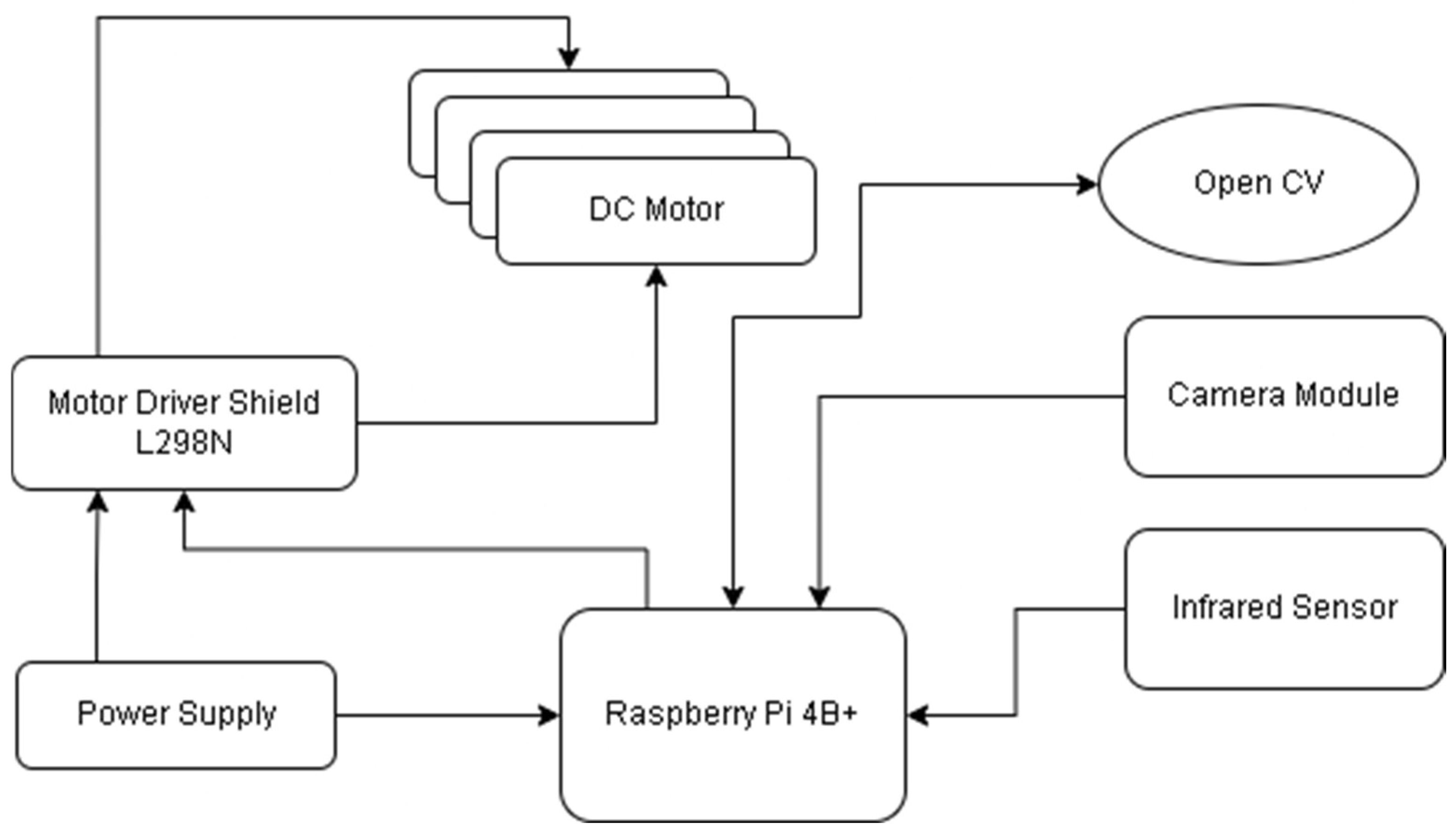
Figure 1 shows block diagram representation of the proposed system.
The camera module and infrared (IR) sensors play crucial roles in providing the data needed for the vehicle to navigate safely and effectively. The camera continuously captures frames, providing real-time visual data of the vehicle’s surroundings. This data is essential for detecting lane markings and other important features on the road. Using OpenCV, the system processes these frames to identify lane boundaries through edge detection and the Hough Transform. The detected lane lines are then used to calculate the vehicle’s deviation from the centerline. Based on the lane detection data, the system adjusts the vehicle’s steering to keep it centered in the lane.
The motor driver uses this information to make precise steering corrections, ensuring the vehicle follows the lane accurately. IR sensors measure the distance to nearby objects by emitting infrared light and detecting the reflected light. This allows the system to detect obstacles in the vehicle’s path. When an obstacle is detected, the system can adjust the vehicle’s speed and direction to avoid collisions. For example, if an obstacle is detected directly ahead, the system might slow down or steer the vehicle to avoid it. While the camera provides detailed visual information about the environment, IR sensors offer quick and reliable distance measurements, especially useful in low-light conditions or for detecting objects that might not be visible to the camera. In the final step of the autonomous vehicle system, the motors execute the commands they receive from the Raspberry Pi. The commands are typically in the form of Pulse Width Modulation (PWM) signals, which control the speed and direction of the motors. The workflow of algorithm for an artificial intelligence-based road lane detection and navigation system for vehicles is shown in
Figure 2.
2.1. Image Acquisition and Enhancement
Camera module captures high-resolution images of the road scene. Real time image enhancement is applied to improve the image quality. Real-time contrast enhancement and noise reduction algorithm ensure clear lane visibility. The contrast adjustment is done by
where,
is the original image,
is the enhanced image, α is the gain (contrast), and β is the bias (brightness).
2.2. Lane Analysis Algorithm
Lane analysis algorithm follows edge detection, boundaries detection followed by segmentation of lane boundaries. Steps performed for lane detection are described below.
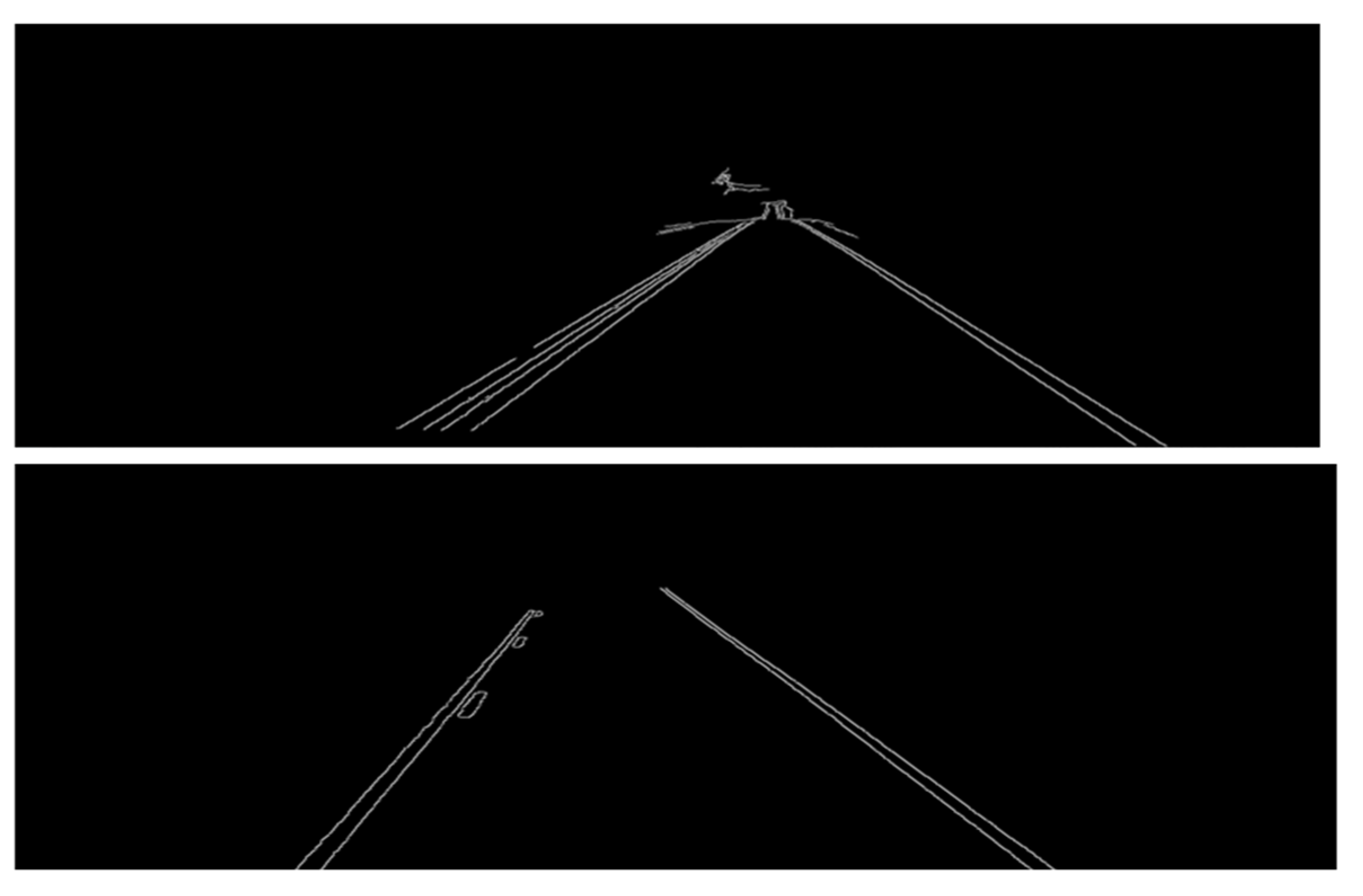
Canny edge detection algorithm is applied to identify edges corresponding to lane markings. Firstly the noise in the image is removed by smoothing the image using a Gaussian filter given by
where
is the standard deviation of the Gaussian distribution. The smoothed image
is obtained by
. Next step is to compute the gradient of smoothed image in horizontal
and vertical
direction using Sobel edge detectors given by
The magnitude
and direction
of the gradient is then calculated by using
Non-maximum suppression is applied to thin out the edges by keeping only local maxima in the gradient direction. For each pixel, the gradient magnitude is checked in the direction of the gradient and the pixel not having maximum value with its neighbor is suppressed.
If
is closest to
and
, then pixel is compared with its horizontal neighbors and vertical neighbors respectively. If
is closest to
and
, then pixel is compared with its diagonal neighbors. Double thresholding is used to classify pixels as strong, weak, or non-relevant edges using high
and low
thresholds as.
Once edges representing lane markings are detected, the system applies the probabilistic Hough Transform to segment these edges into distinct line features. This technique identifies the parameters of lines that best fit the edge points, representing the detected lanes. By segmenting the detected edges into individual line segments, the system can accurately represent the lane boundaries, enabling precise lane detection and navigation.
In the Hough Transform for lines, each pixel in the image space is mapped to a sinusoidal curve in the Hough parameter space , where is the perpendicular distance from the origin to the line and is the angle of the line normal. The parametric equation of a line in polar coordinates is .
where: is the distance from the origin to the closest point on the line and is the angle between the x-axis and the line perpendicular to the line. A 2D array (accumulator) is defined to represent the parameter space . The dimensions of the accumulator array depend on the ranges of . Typically, and . Here is the diagonal length of the image of dimension . For each edge pixel , calculate the possible values using the line equation and increment the corresponding cell in the accumulator. Identify peaks in the accumulator array. These peaks represent the parameters of the most prominent lines in the image.
2.3. Guidance and Control
Calculating the vehicle’s deviation from the centerline is crucial for making steering adjustments. This keeps the vehicle aligned with the center of the lane, promoting safe driving and preventing lane departure. It basically determine the vehicle’s deviation from the lane centerline. Calculating the centerline as the average of the left and right lane boundaries provides a reference point for the vehicle’s desired position on the road. The centerline of the lane is calculated using
, Where
and
are the x-coordinates of the detected left and right lane boundaries at a particular y-coordinate. Knowing the vehicle’s position relative to the image frame allows for an accurate calculation of the deviation. The center of the image typically corresponds to the center of the vehicle. If the vehicle’s camera is centered, the vehicle’s x-position is the center of the image
, W is the image width. The deviation Δx is the primary metric used for steering corrections. Positive or negative deviations indicate which direction the vehicle needs to move to stay centered in the lane.
The sign of Δx indicates whether the vehicle is left or right of the lane centerline. Dynamically adjusting the vehicle’s speed based on lane curvature ensures that the vehicle navigates turns safely and comfortably. Sharper turns require slower speeds to maintain control and stability. Aim of this step is to adjust the vehicle’s speed based on lane curvature and environmental factors. The radius of curvature
R quantifies how sharp a turn is. A smaller radius indicates a sharper turn, which requires slower speeds to navigate safely. Conversely, a larger radius indicates a gentler turn, allowing for higher speeds. Using the polynomial fit of the lane lines, calculate the radius of curvature R at a specific point.
Adjusting speed proportional to the curvature helps maintain vehicle stability and passenger comfort. On sharp turns, reducing speed prevents the vehicle from skidding or losing control, while on gentle curves, higher speeds can be maintained without compromising safety. Dynamically adjust speed v based on curvature R as v∝R. For example, a smaller R (sharper curve) requires a lower speed.
2.4. Integration of Sensing and Actuation
The Raspberry Pi generates PWM signals based on the control algorithms, particularly the output from the PID controller. These signals are sent to motor drivers, which act as intermediaries between the Raspberry Pi and the motors. The motor drivers amplify the PWM signals to levels suitable for driving the motors. The PWM signals determine the motors’ speed and direction. By adjusting the duty cycle of the PWM signal (i.e., the percentage of time the signal is “on” versus “off”), the system can control how fast the motors spin. The direction is controlled by varying the polarity of the signal. The motors translate these electrical signals into mechanical motion, propelling the vehicle forward, backward, or steering it left or right. The precise control of speed and direction allows the vehicle to follow the detected lane accurately, making necessary adjustments to stay centered and navigate curves or turns smoothly.
The information from both the camera and IR sensors is fused to create a comprehensive understanding of the vehicle’s environment. The camera’s detailed visual data combined with the IR sensor’s distance measurements ensure that the vehicle can navigate accurately and safely. The Raspberry Pi processes the data from both sensors in real time, using image processing techniques and sensor fusion algorithms to make immediate decisions about steering and speed adjustments. The system operates in a continuous feedback loop where sensor data is constantly updated, processed, and used to adjust the vehicle’s movement. This ensures that the vehicle responds dynamically to changes in the environment, such as new obstacles or changes in lane direction.
3. Results
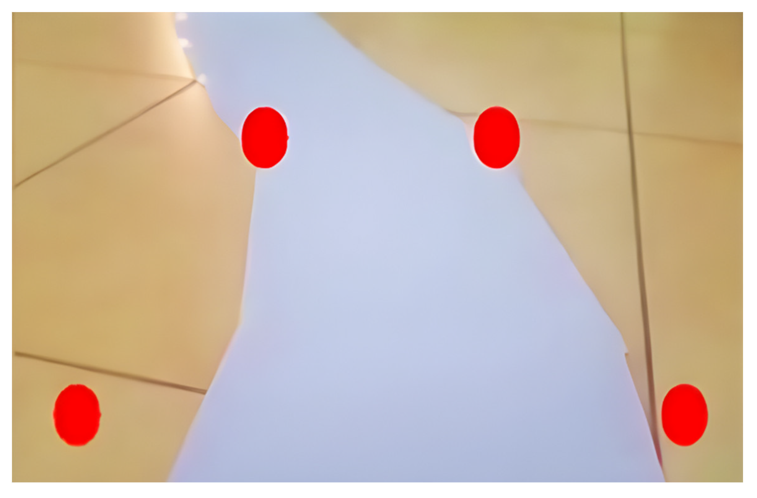
The system’s output can be viewed on the virtual machine instance on the PC that is connected to our Raspberry Pi 4B+. We are using a VNC server and VNC viewer to remotely access the Raspberry Pi’s desktop and control it using the local system’s mouse and keyboard. The output is demonstrated into 6 different intermediate outputs to facilitate better understanding and calibration of the camera with the track.
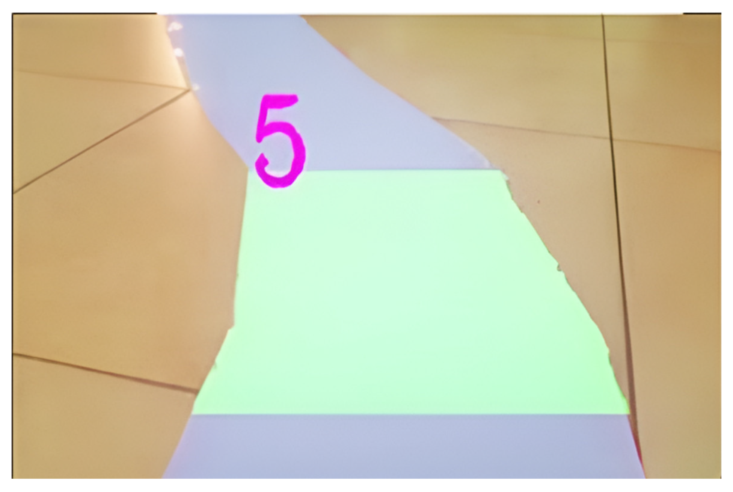
Figure 3 shows the raw image captured by the camera, which is unprocessed. The raw image is processed to determine the region of interest for the track as shown in
Figure 4. This ensures that for the subsequent steps, the image is confined to the ROI.
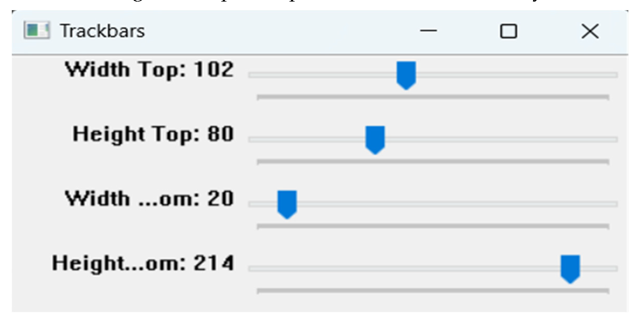
To enhance user-friendliness, trackbars have been added to allow real-time adjustments to the ROI as shown in
Figure 5. The panel allows you to adjust the width (top and bottom) and height (top and bottom) of the ROI. These settings define the exact area of the road that the lane detection algorithm will analyze, enabling customization based on different road conditions and camera angles. By adjusting these parameters, you can ensure that the lane detection system effectively detects and tracks lane markings with optimal performance and accuracy.
In the next step, calculation of the midpoint of the lane is calibrated by ROI in order to keep the vehicle in the center of the lane as shown in
Figure 6.
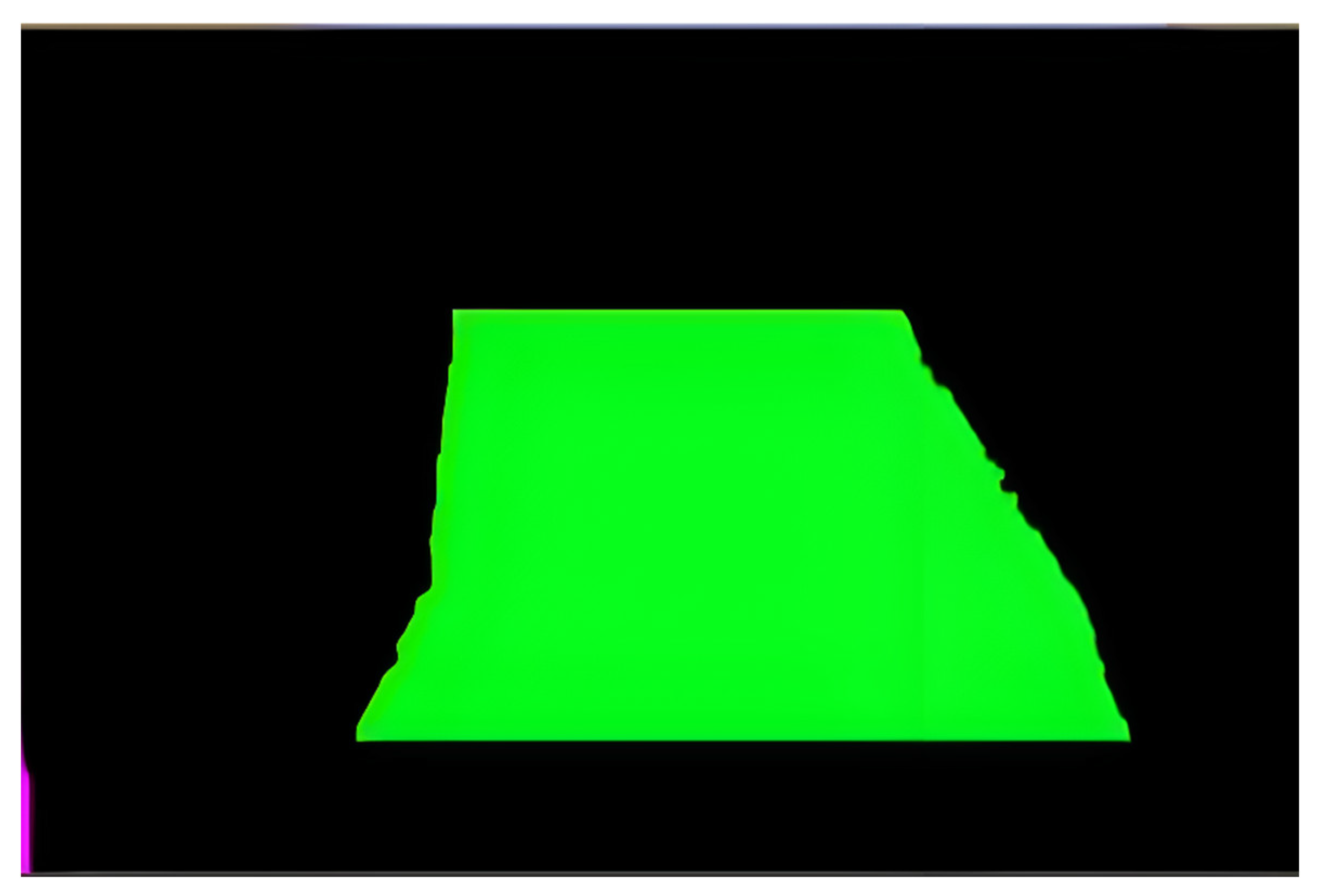
Next, the final lane is created to guide the vehicle along the curve, which is indicated by an integer and calculated using the ROI as a boundary and the midpoint of the lane. This is shown in
Figure 7.
Figure 7 displays the result after the final lane has been calculated, allowing the user to easily review and make necessary adjustments to the system according to their needs.
These steps are used to generate a number that moves a vehicle either in a straight line or along a curved path. The motors use PWM to adjust their speed and navigate the vehicle along the curve based on its degree. Additionally, an infrared sensor is employed to halt the vehicle when an obstacle is detected in its path. The number which is displayed on the output shows that on which direction and how much the vehicle should move. If the number is positive it will move in left direction and for the negative number it will move the right direction as shown in
Figure 9.
4. Discussion
4.1. Navigation
After analyzing sensor data, such as camera images and proximity sensor readings, the next step is to determine the vehicle’s position, orientation, and surroundings. Lane detection algorithms process camera images to identify lane markings and determine the vehicle’s position within the lane. Object detection algorithms analyze camera images to detect obstacles or road signs that may affect the vehicle’s path. Proximity sensors detect nearby objects and trigger collision avoidance mechanisms, such as applying brakes or steering away from obstacles. Control algorithms calculate motor commands based on sensor inputs and predefined navigation algorithms to steer the vehicle along the desired path while maintaining a safe distance from obstacles. These decisions are executed in real-time, enabling the autonomous vehicle to navigate through its environment safely and efficiently.
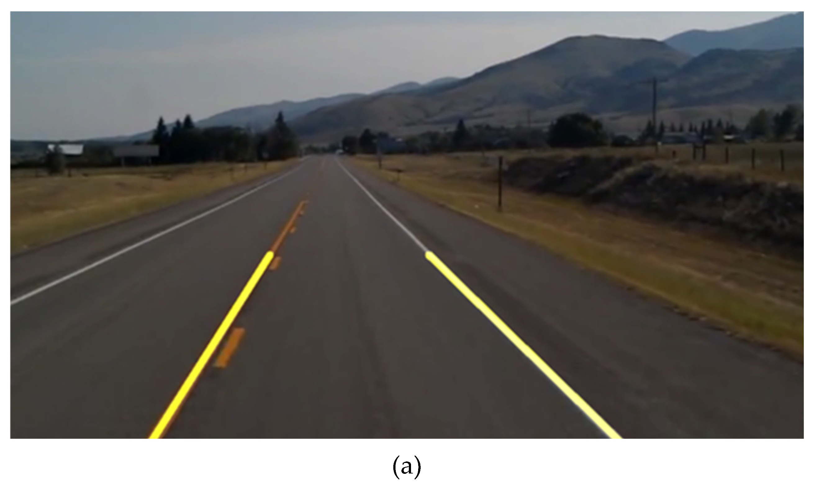
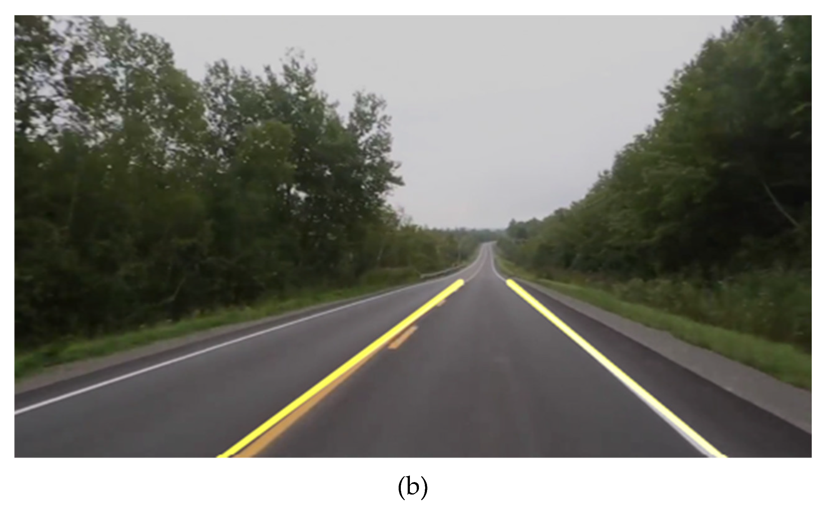
Figure 10 shows the output window displays the overlapping of detected lanes on the actual road. This visualization is essential as it provides real-time feedback on the performance of the lane detection algorithm. By overlaying the detected lane markings onto the live feed of the road, we can assess the accuracy and reliability of the detection process. This visual feedback allows us to validate the effectiveness of the algorithm in correctly identifying lane boundaries and tracking their position relative to the vehicle’s trajectory. Additionally, by comparing the detected lanes with the actual road markings, we can identify any discrepancies or errors, enabling us to refine and optimize the algorithm for improved accuracy and robustness. Ultimately, visualizing the detected lanes overlaid on the actual road facilitates comprehensive evaluation and validation of the lane detection system’s performance in real-world conditions.
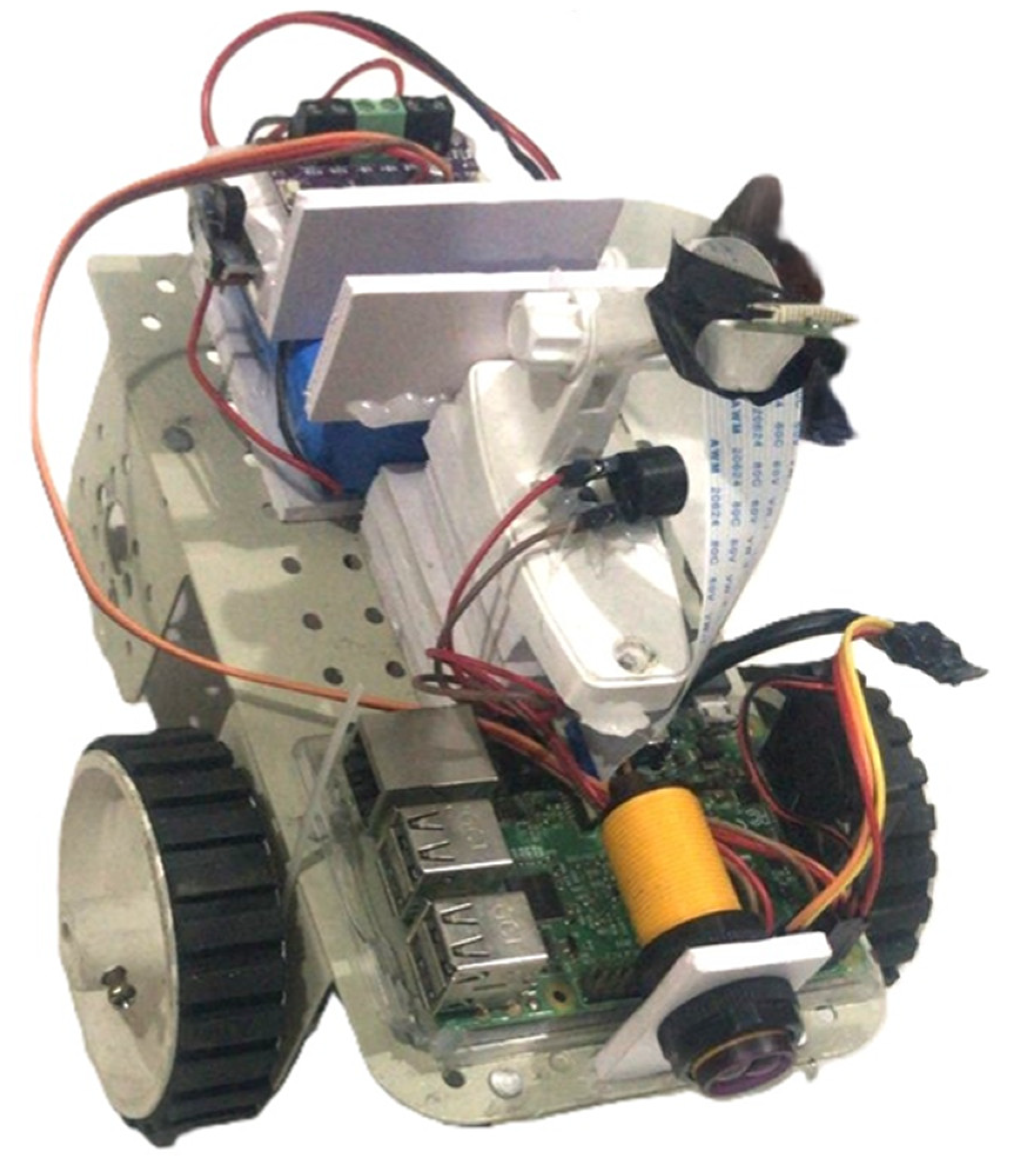
The prototype of the proposed system is shown in
Figure 11. The key component of the components for the autonomous vehicle system are proximity IR sensors for obstacle detection, a Raspberry Pi microcontroller for processing data and controlling movement, a power bank for continuous operation, motors for propulsion and steering, a motor driver for power regulation, and a front-facing camera for capturing real-time visual data. These components collectively enable the vehicle to perceive its environment and navigate autonomously.
4.2. Lane Detection Status
In our analysis, we aim to specify the configuration of coordinates crucial for determining the Region of Interest (ROI) along the vehicle’s path. These coordinates, including top width, top height, bottom width, and bottom height, play a significant role in accurately detecting lanes on the road. Furthermore, we assess the efficiency of the lane detection algorithm concerning Frames Per Second (FPS) and the speed of motors. Our findings provide insights into how varying FPS and motor speeds affect the accuracy of lane detection, particularly on straight and curve lanes. The coordinate configuration used to identify the Region of Interest (ROI) for the vehicle’s journey and lane detection status is depicted in
Table 1.
A precise zone on the road is defined by each set of coordinates, which is essential for lane detection. The efficacy of the detection algorithm is revealed by the “Lane Detection Status” column, which classifies the detected regions according to whether the full lane, a portion of the lane, or no lane is detected.
Table 2 evaluates the efficiency of the detection algorithm concerning Frames Per Second (FPS) and the speed of motors. The results indicate that higher FPS and medium motor speed contribute to better detection accuracy, particularly evident in 17 fps scenarios. However, low FPS and high motor speed adversely impact detection performance, highlighting the importance of optimizing these parameters for optimal results in autonomous vehicle systems. Our research efforts finally resulted in the creation of an enhanced lane detecting system for self-driving cars, which makes use of a blend of machine learning algorithms and image processing techniques. Real-time visual data processing has been accomplished through the smooth integration of OpenCV and Python, demonstrating the system’s capacity to precisely detect lane markers under a variety of driving scenarios. The technology is feasible for deployment in automotive environments thanks in large part to the Raspberry Pi platform’s low cost for on-board processing. Its user-friendly interface, which offers clear navigation instructions, is expected to greatly improve vehicle safety and driver assistance.
5. Conclusions
The proposed artificial intelligence-based autonomous road lane detection and navigation system demonstrates significant advancements in the field of autonomous driving. By accurately detecting and analyzing road lanes in real-time, the system enhances safety, navigation, and traffic management for vehicles. The integration of image processing techniques with sensors and actuators ensures comprehensive and reliable autonomous navigation. The system’s performance, as evidenced by its ability to maintain frame rates of up to 17 FPS, underscores its efficiency and practicality for real-world applications. Furthermore, the evaluation of lane detection accuracy on both straight and curved lanes highlights the robustness of the system under various conditions. The results, showing full lane detection, partial lane detection, and no detection statuses, validate the effectiveness of the proposed approach. This research contributes to the ongoing development of autonomous driving technologies, providing a solid foundation for future enhancements and implementations. Clear navigation instructions are ensured by the system’s user-friendly interface, improving road safety and driver support. High lane detection accuracy and lane tracking confidence is demonstrated through evaluation, providing a solid basis for real-world implementation in autonomous car navigation systems. Future work may concentrate on improving the system’s capacity to adjust to intricate driving situations, incorporating more sensor modalities, and increasing computational efficiency for wider scalability.
6. Patents
Patent titled AN ARTIFICIAL INTELLIGENCE BASED ROAD LANE DETECTION AND NAVIGATION SYSTEM FOR VEHICLE by the applicants CHITRIV, Yogita U., TARTE, Yashraj M., TALATULE, Nikhil A., SABLE, Bhargav R., TAYWADE, Chetan S. is published on 15 December 2023 and under examination for grant by Intellectual Property Rights Office, India. Application Number: 202321048690
Author Contributions
The following statements should be used “Conceptualization, Y.D. ; methodology, N.T.; software, Y.T.; validation, N.T., Y.T. and Y.D.; formal analysis, B.S.; investigation, Y.T.; resources, C.T.; data curation, B.S. and C. T.; writing—original draft preparation, Y.T., N. T. and B. S.; writing—review and editing, Y.D.; visualization, N. T. and Y. T.; supervision, Y.D.; project administration, Y.D.; funding acquisition, R.U. All authors have read and agreed to the published version of the manuscript.
Funding
This research received no external funding.
Institutional Review Board Statement
Not applicable.
Data Availability Statement
No new data was created.
Conflicts of Interest
The authors declare no conflicts of interest. And The funders had no role in the design of the study; in the collection, analyses, or interpretation of data; in the writing of the manuscript; or in the decision to publish the results.
References
- Aly, M. Real Time Detection of Lane Markers in Urban Streets. In Proceedings of the IEEE Intelligent Vehicles Symposium, Eindhoven, The Netherlands, 4–6 June 2008. [Google Scholar]
- LeCun, Y.; Bottou, L.; Bengio, Y.; Haffner, P. Gradient-Based Learning Applied to Document Recognition. Proc. IEEE 1998, 86, 2278–2324. [Google Scholar] [CrossRef]
- Long, J.; Shelhamer, E.; Darrell, T. Fully Convolutional Networks for Semantic Segmentation. In Proceedings of the IEEE Conference on Computer Vision and Pattern Recognition (CVPR), Boston, MA, USA, 7–12 June 2015. [Google Scholar]
- Bojarski, M.; Testa, D.D.; Dworakowski, D.; Firner, B.; Flepp, B.; Goyal, P.; Jackel, L.D.; Monfort, M.; Muller, U.; Zhang, J.; Zhang, X.; Zhao, J.; Zieba, K. End to End Learning for Self-Driving Cars. arXiv 2016, arXiv:1604.07316. [Google Scholar]
- Chen, L.-C.; Papandreou, G.; Kokkinos, I.; Murphy, K.; Yuille, A.L. DeepLab: Semantic Image Segmentation with Deep Convolutional Nets, Atrous Convolution, and Fully Connected CRFs. IEEE Trans. Pattern Anal. Mach. Intell. 2018, 40, 834–848. [Google Scholar] [CrossRef]
- He, K.; Gkioxari, G.; Dollar, P.; Girshick, R. Mask R-CNN. In Proceedings of the IEEE International Conference on Computer Vision (ICCV), Venice, Italy, 22–29 October 2017. [Google Scholar]
- Bewley, A.; Ge, Z.; Ott, L.; Ramos, F.; Upcroft, B. Simple Lane Detection and Tracking for Highway Driving. IEEE Trans. Intell. Transp. Syst. 2016, 17, 1682–1686. [Google Scholar]
- Krauss, R. Combining Raspberry Pi and Arduino to Form a Low-Cost, Real-Time Autonomous Vehicle Platform. In Proceedings of the IEEE, Gothenburg, Sweden, 19–22 June 2016. [Google Scholar]
- Jain, A.K. Working Model of Self-Driving Car Using Convolutional Neural Network, Raspberry Pi and Arduino. In Proceedings of the IEEE, Barcelona, Spain, 5–8 March 2018. [Google Scholar]
- Ariyanto, M.; Haryanto, I.; Setiawan, J.D. Real-Time Image Processing Method Using Raspberry Pi for a Car Model. In Proceedings of the IEEE, Singapore, 14–17 October 2019. [Google Scholar]
- Mariaraja, P.; Manigandan, T.; Arun, S. Design and Implementation of Advanced Automatic Driving System Using Raspberry Pi. In Proceedings of the IEEE, Berlin, Germany, 1–3 December 2020. [Google Scholar]
- Caltagirone, L.; Scheidegger, S.; Svensson, L.; Wahde, M. Fast LIDAR-Based Road Detection Using Fully Convolutional Neural Networks. In Proceedings of the IEEE Intelligent Vehicles Symposium (IV), Los Angeles, CA, USA, 11–14 June 2017. [Google Scholar]
- Kolekar, M.H.; Ramesh, A.; Mantri, K. LiDAR and Camera Fusion Approach for Object Distance Estimation in Autonomous Vehicles. In Proceedings of the International Conference on Intelligent Autonomous Systems (ICoIAS), Singapore, 1–3 March 2018. [Google Scholar]
- Hafeez, M.A.; Malik, H.; Shaukat, S.F.; Ali, T.; Tariq, M.; Asad, M.M. Low-Cost Solutions for Autonomous Vehicles. IEEE Access 2018, 6, 54355–54372. [Google Scholar]
- Landman, J.A.; Darzi, A.; Athanasiou, T. User Interface Design for Autonomous Vehicles. Appl. Ergon. 2019, 77, 124–134. [Google Scholar]
- Jain, A.; Singh, S.; Sharma, P.; Arora, A. Lane Detection Using Deep Learning in Self-Driving Cars. J. Artif. Intell. Syst. 2020, 2, 45–57. [Google Scholar]
- Liu, D.; Jin, L.; Luo, W.; Duan, J.; Tan, J. Deep Learning for Real-Time Lane Detection: A Survey. IEEE Trans. Intell. Veh. 2020, 5, 292–303. [Google Scholar]
- Sohn, K.; Jung, S. Recent Advancements in Lane Detection for Autonomous Driving. IEEE Sens. J. 2020, 20, 991–1018. [Google Scholar]
- Xu, T.; Zhang, X.; Li, H.; Yang, W. High-Speed Lane Detection for Autonomous Vehicles. arXiv 2022, arXiv:2206.07389. [Google Scholar]
|
Disclaimer/Publisher’s Note: The statements, opinions and data contained in all publications are solely those of the individual author(s) and contributor(s) and not of MDPI and/or the editor(s). MDPI and/or the editor(s) disclaim responsibility for any injury to people or property resulting from any ideas, methods, instructions or products referred to in the content. |
© 2024 by the authors. Licensee MDPI, Basel, Switzerland. This article is an open access article distributed under the terms and conditions of the Creative Commons Attribution (CC BY) license (http://creativecommons.org/licenses/by/4.0/).
