1. Introduction
The increase in space activities has resulted in a buildup of orbital debris, which poses a significant threat to spacecraft and satellites in Earth’s orbit. This debris includes man-made components like spent satellites, rockets, and paint chips, capable of causing hypervelocity impacts with speeds of up to 15 km/s [
1,
2,
3]. The outcomes of such impacts range from material ablation to the release of spacecraft material as debris clouds. A great deal of effort has been devoted to the hypervelocity impact simulations to comprehend how materials and structures behave under such extreme circumstances [
4,
5,
6,
7,
8,
9,
10,
11,
12].
The threat posed by hypervelocity impacts from micrometeoroids and orbital debris is a significant concern, given their capacity to inflict damage on spacecraft and satellite components [
13]. Evaluating the survivability of Earth satellites against hypervelocity impacts is crucial, as even millimeter-sized objects moving at orbital velocities can have harmful effects on space structures [
14].
The investigation of hypervelocity impacts from orbital debris via experiments plays a pivotal role in spacecraft protection strategies and ensuring the structural integrity of space structures against potential damage. However, conducting experimental studies on hypervelocity impacts presents several challenges. These include difficulties in accurately replicating real-world conditions [
15], logistical complexities and high costs [
16], and limited capability to capture detailed data during impact events [
17].
Due to these challenges, while experimental research has been the primary focus in the past, the complexity of impact dynamics and the growing number of potential shielding designs have underscored the need for improved computer-aided design tools. These tools are essential for efficiently evaluating a wide range of candidate shielding concepts, characterizing three-dimensional performance, and addressing the challenges posed by impact velocity, obliquity, and material failure effects. Additionally, the shift towards faster and cost-effective spacecraft design emphasizes the importance of simulation-based approaches over traditional experimental methods, especially given the diverse impact velocities and kinetic energies encountered in hypervelocity scenarios [
18].
As a result, several numerical methods [
19,
20] are developed and employed in the study of hypervelocity impacts, aiding in understanding hypervelocity impact phenomena and optimizing protective measures. One prominent numerical method in hypervelocity impact research is the Material Point Method (MPM). This method emerges as a powerful computational tool that combines the advantages of both Lagrangian and Eulerian methods, making it well-suited for modeling large deformation and fragmentation phenomena during hypervelocity impacts. MPM was introduced by Sulsky et al. [
21] as an extension of particle-in-cell methods, initially employed for modeling highly distorted fluid flow. MPM primarily discretizes media into Lagrangian material points which move with the material, carrying essential information such as velocities, strain, and stresses [
22,
23]. This feature makes MPM particularly suitable for modeling highly distorted fluid flow and complex material behaviors. Alongside other numerical methods, MPM is proven to be a versatile and effective tool in hypervelocity impact research, enabling researchers to simulate impact phenomena.
Within this context, a computational framework is presented using the Material Point Method (MPM) for evaluating the risk of orbital debris impact on space structures. The framework incorporates various parameters influencing the impact phenomenon to enhance protection strategies against hypervelocity impacts in space. Numerical simulations are performed using an open-source MPM based code [
24,
25,
26], supplemented by an in-house preprocessor developed in MATLAB to prepare the configuration setup file. This preprocessor simplifies the configuration setup process by enabling the generation of input files for diverse scenarios involving different projectile and target geometries configurations. To explore the geometric influences on hypervelocity impact, four distinct projectile shapes (square prism, triangular prism, cone, and ogival) are simulated along with three different inclined positions (θ=0°, 30°, and 60°) of the rectangular prism target. Employing the Johnson-Cook plasticity model and Mie-Grüneisen equation of state (EOS) [
27,
28], several simulations are performed and the influence of projectile shape and oblique impact angles on debris formation and target damage are investigated. The results reveal significant variations in debris cloud morphology on both the front and rear faces of the target, influenced by the shape and impact angle of the projectiles.
2. The Numerical Method
The numerical model employed in this study adopts the Material Point Method (MPM), which was originally developed in Ref. [
24,
25,
26]. In this method, a continuum body is discretized using Lagrangian material points, also referred to as particles, which track the material properties throughout the deformation process. Each material point in MPM is associated with properties such as position, mass, density, velocity, deformation gradient, stress tensor, temperature, and other internal variables required for the constitutive model, collectively providing a Lagrangian description of the continuum body. The MPM approach ensures mass conservation as each material point maintains a fixed mass throughout the simulation [
24].
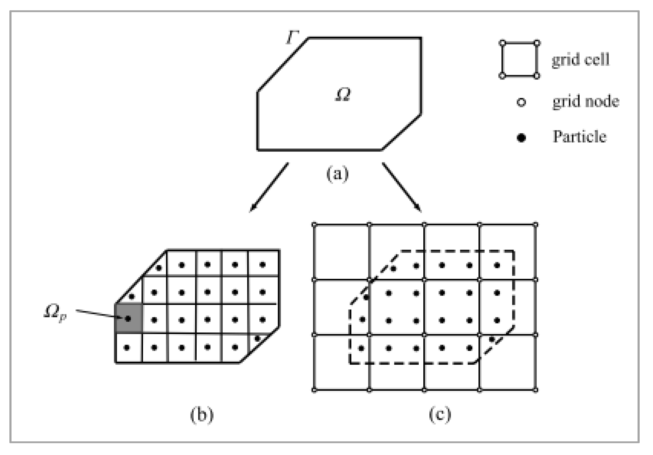
The discretization is made in the material domain
using a collection of material particles, moving through an Eulerian background grid. Each particle has a subdomain
along with all its associated attributes such as mass, momentum, energy, strain, stress, and internal state variables essential for history-dependent constitutive modeling. A typical discretization for the MPM is sketched in
Figure 1 [
24].
The MPM utilizes the updated Lagrangian approach in which the stress and strain measures are defined based on the current configuration, specifically using the Cauchy stress and rate of deformation, while derivatives and integrals are calculated using the Eulerian coordinate
. According to this approach the weak form for the momentum equation and the traction boundary condition is given as [
24].
Here,
is the displacement field,
is the deformed configuration,
is the traction boundary,
is the Cauchy stress tensor, ρ is the current density given by Equation (2) and
is the body force per unit mass.
Here, the particle is denoted by subscript
, the mass of the particle is
, while the spatial coordinate of the particle is
.
is the total number of the particles, and
is the Dirac delta function. When the approximated material density given in Equation (2) is substituted in the weak form of momentum equation, we reach [
24]
Where , , , , and is the thickness of the fictitious layer used for conversion of a surface integral to a volume integral. Noting that the displacement of the particle is and its derivative is .
In MPM, the grid is used transiently for gradient and divergence calculations, without retaining permanent information. This flexibility allows the grid to be fixed in space while particles transport material properties, minimizing errors. During the convective phase, the grid is reset to its original position, while particles maintain their current positions. Velocity reconstruction on the new grid can be achieved using consistent and lumped grid mass matrices [
29].
In the original MPM formulation by Sulsky [
21], the method functions as an updated Lagrangian scheme. The simulated body’s space during deformation is discretized by a background grid where the momentum balance equation is solved. The use of a grid in MPM offers several advantages. It eliminates the need for direct computation of particle-particle interactions, simplifies collision treatment through the background Eulerian grid, and enables efficient momentum equation solution due to fewer grid points compared to particles. Typically, a fixed regular Cartesian grid is employed throughout the simulation for computational efficiency [
29].
In order to compute the hypervelocity response of the projectile-target system, the MPM uses a constitutive model selected for the particular simulation. In the simulations Johnson–Cook plasticity model with failure is used which is a suitable constitutive model for hypervelocity impact. This model is employed with Mie-Grüneisen’s equation of state (EOS) which is used to determine the pressure within a shock-compressed solid [
27,
28]. The parameters for the selected constitutive model and variables for the equation of state and the material properties are given in
Table 1.
3. Results and Discussion
We investigate the hypervelocity impact response of several projectile/target configurations to high-speeds using various projectile shapes and oblique scenarios. By analyzing impact dynamics and the morphology of the debris cloud, we aim to provide valuable insights into the behavior of hypervelocity impacts and their relevance to the protection of space structures.
We first present a comparison between our results and those of an experiment conducted by Anderson et al. [
27]. In this experiment, the impact of a lead spherical projectile into a lead target at an angle of 90° was captured by a high speed camera, shown in
Figure 2a. The diameter of the spherical projectile was approximately 2.4 times of the plate thickness and its initial velocity was set to 6580 m/s. Using the same physical parameters and geometrical configuration, we carry out a hypervelocity impact simulation and display the deformation result in
Figure 2b.
From a qualitative perspective, as it is seen from
Figure 2, the morphology of the debris cloud from both results shows good agreement. Additionally, Ref. [
30] could be addressed for a similar comparison using the same method and yet with better resolution of particles.
Prior to demonstrating the simulation results, an important aspect worth mentioning is the development of an in-house preprocessor to generate input files for simulations of each projectile/target configuration. This preprocessor simplifies the process by allowing users to create the necessary input files required to execute the code and to outline the user’s specific preferences for the problem. It is developed using MATLAB and comprises three key elements: the solver setup, grid files for both projectile and target, and physical definitions including boundary conditions.
The current version of MPM3D-F90 [
24,
25,
26] has built-in functions to define three bodies: block, sphere, and particles. To enhance the ability of the current code, bodies with a variety of shapes are included within this tool. These shapes include prisms (triangular, square, pentagonal, and hexagonal), spheres (solid and hollow), cones (truncated cone), and ogivals. Among these shapes, a square prism, a triangular prism, a truncated cone, and an ogival shape are chosen according to their relevance to simulate an orbital debris impact.
In addition to the inclusion of a variety of shapes, the relative location of the projectile and target can be adjusted within this tool, making the oblique impact preprocessing step quite easy. To manage computational costs effectively, symmetry boundary conditions can also be imposed using this tool. This enables users to conveniently set up the problem for either the entire domain or just half of it. Upon selection, the projectile and target are divided into their respective halves along the pertinent symmetry plane.
By using this preprocessor, the generation of input files for various physical cases and projectile-target combinations becomes straightforward. In the forthcoming sections, including the previously presented validation study, all input files are generated for various combinations of projectile shapes and target configurations via this preprocessor.
3.1. The Influence of Projectile Shapes
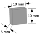
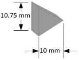
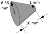
The influence of shape on orbital debris impact and the ballistic performance of the shield system is a critical aspect of space structure design. The shape and orientation of debris significantly affect the ballistic performance of shielding systems. The variations in projectile geometry can influence the distribution of impact forces and the formation of shock waves within the target material, thereby affecting the overall damage profile. In order to explore these effects, we simulate the hypervelocity impacts using three different lead projectile shapes. The geometrical properties of these projectiles are presented in detail in
Table 2. The target material is aluminum and has dimensions of 200 mm×100 mm with a thickness of 5 mm. The initial impact velocity is set to 4000 m/s. Material failure is considered to occur when the equivalent plastic strain reaches 1.6 mm/mm for the target and 3.0 mm/mm for the projectile, indicating an inability to sustain deviatoric stress. The total number of model particles for each projectile/target configuration is also provided in
Table 2.
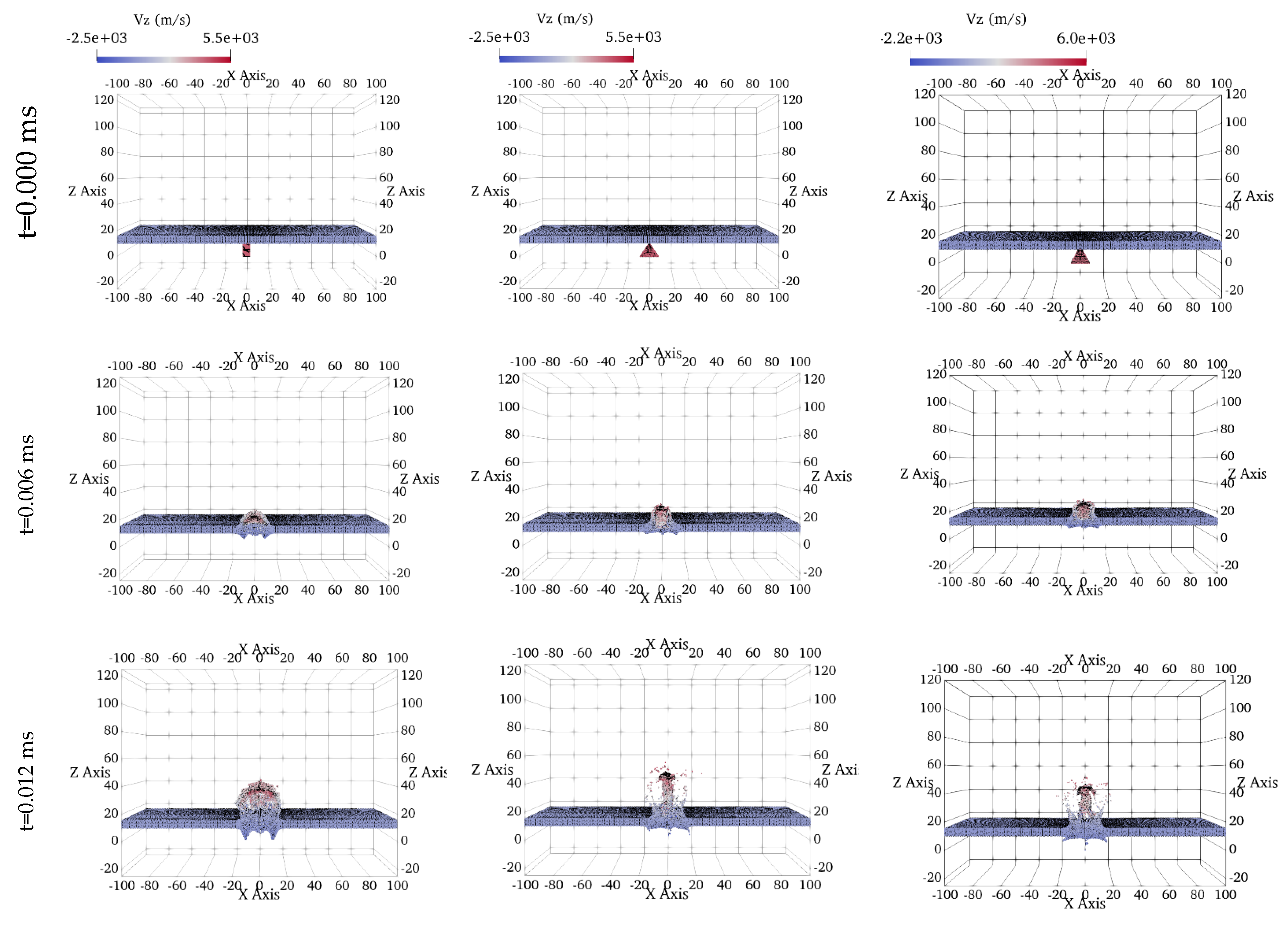
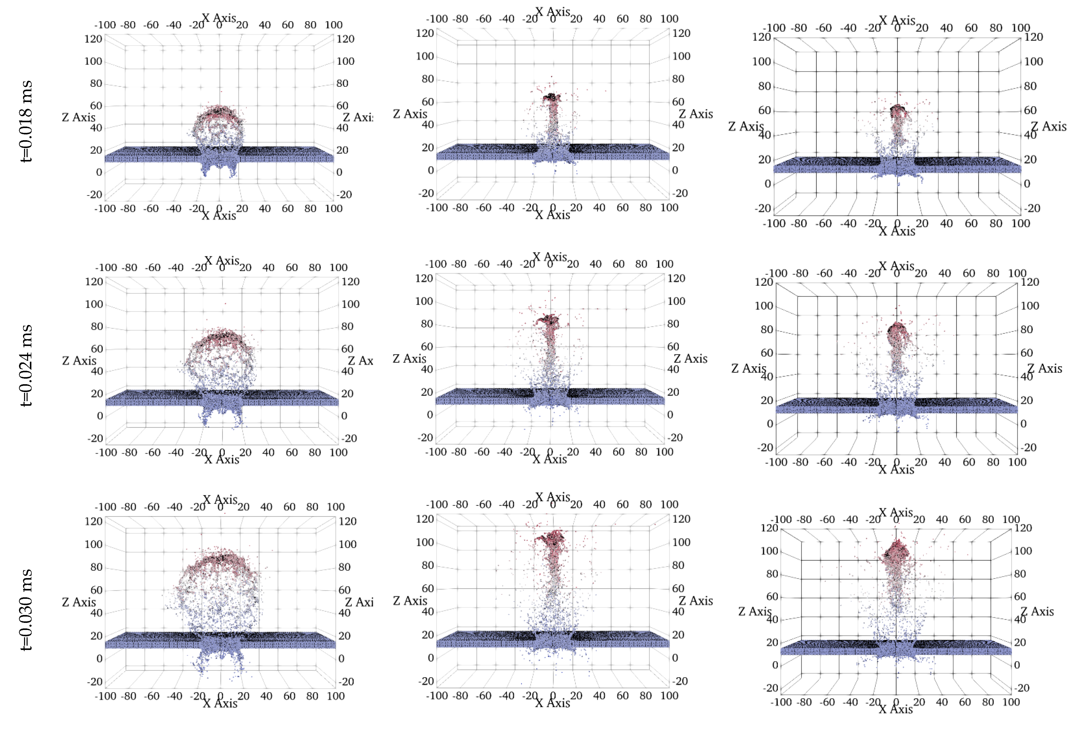
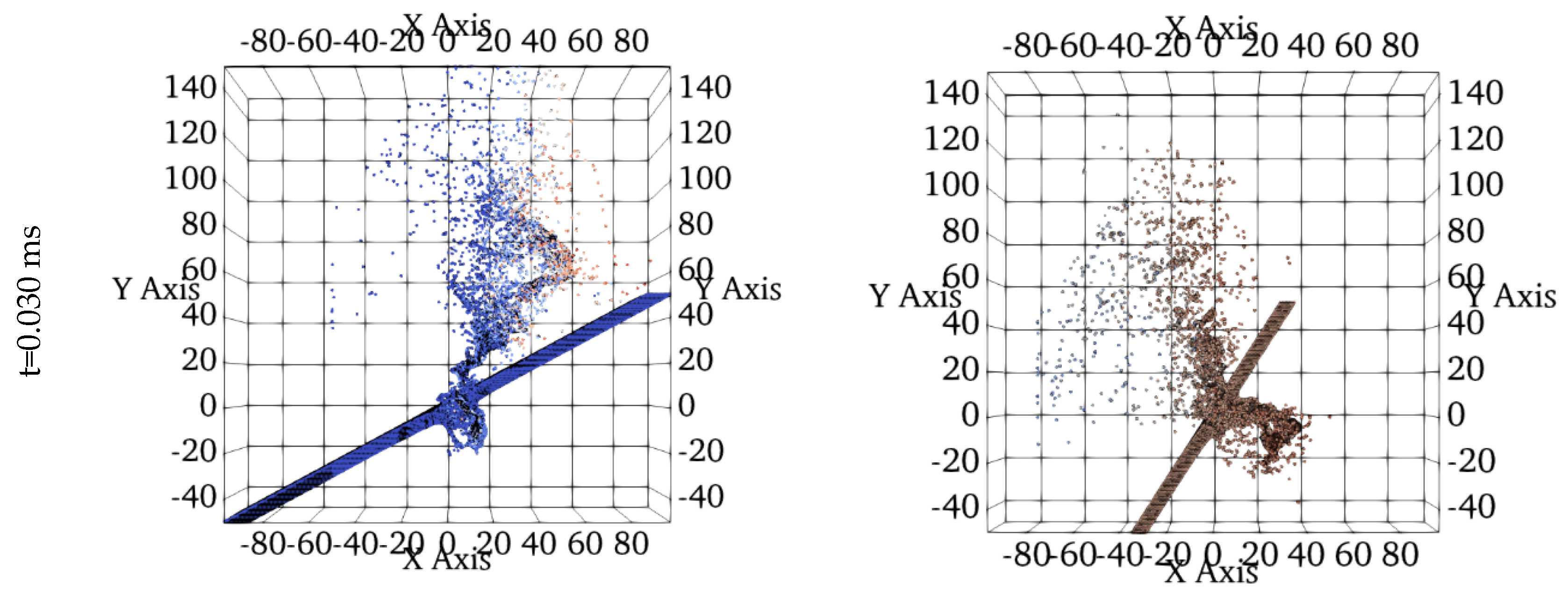
The deformation results are captured at distinct time intervals, t=0.000, 0.006, 0.018, 0.024, and 0.030 ms and are plotted in
Figure 3. Each column within this matrix of figures represents sequential snapshots that plots the impact scenarios involving square prism, triangular prism, and truncated cone-shaped projectiles. Notably, the color gradient employed in these figures displays the velocity variations along the z-direction.
Each projectile has the same volume of 500 mm³ and is made of lead. The rectangular target is hit from the center at an impact angle of 90°. As evident from these figures, the projectile’s shape significantly influences the structure of the debris cloud, showing distinct variations from impact initiation to 0.030 ms post-impact. This influence becomes increasingly pronounced as the impact event progresses.
In the first column of the results, corresponding to the square prism impact, a typical debris cloud formation is observed, while the debris clouds resulting from impacts of triangular prism and truncated cone-shaped projectiles, shown in the second and third columns, exhibit distinct formations. The scattering behavior of debris on the front formation aligns with the shape of the projectiles. Although the overall structures of the debris cloud vary for different shaped projectiles, a consistent external bubble is maintained for all projectile types during the early stages of impact (t < 0.012 ms). However, beyond t > 0.012 ms, the external bubble of the major debris structure becomes scattered, particularly for the triangular prism and truncated cone-shaped projectiles.
Notably, projectiles with sharp noses, such as those of the triangular prism and truncated cone, induce deeper penetration craters. Following perforation, the particles from these sharp-nosed projectiles exhibit cohesive motion, resembling the formation of a coherent debris cloud characterized by a centrally aligned rod-like structure. While this phenomenon may not be immediately apparent in the early stages of impact, its structure becomes increasingly pronounced over time.
Upon investigating the rear formation of the debris clouds in
Figure 3, it becomes evident that the amount of ejected debris from the rear-face is greater for blunt-shaped projectiles like the square prism in our case. In contrast, projectiles with sharper noses result in fewer particles being ejected from the back face of the target. This observation is consistent with the deeper perforation behavior exhibited by sharp-nosed projectiles.
Furthermore, the angle at which debris is ejected from the rear surface of the target becomes increasingly visible and distinct as the impact progresses for each projectile shape. Notably, for sharp-nosed projectiles, the ejection angles are sharper compared to those of blunt-shaped projectiles.
Investigation of debris cloud formations resulting from impacts by different projectile shapes revealed unique debris dispersion patterns for each projectile type. Sharp-nosed projectiles, like the triangular prism and truncated cone, were observed to penetrate deeper into the target material compared to the square prism. This deeper penetration resulted in the formation of larger craters and potentially more extensive damage. Additionally, sharp-nosed projectiles exhibited more directional scattering, leading to a focused ejection of debris particles away from the impact region. Conversely, the blunt-shaped square prism produced more isotropic scattering, dispersing debris in multiple directions.
3.2. Oblique Impact Simulations
The oblique impact involve debris striking a target surface at an angle and poses significant challenges for space structures and spacecraft that requires special attention. Understanding the effects of oblique impacts is crucial for designing effective shielding and protective measures in space environments [
9,
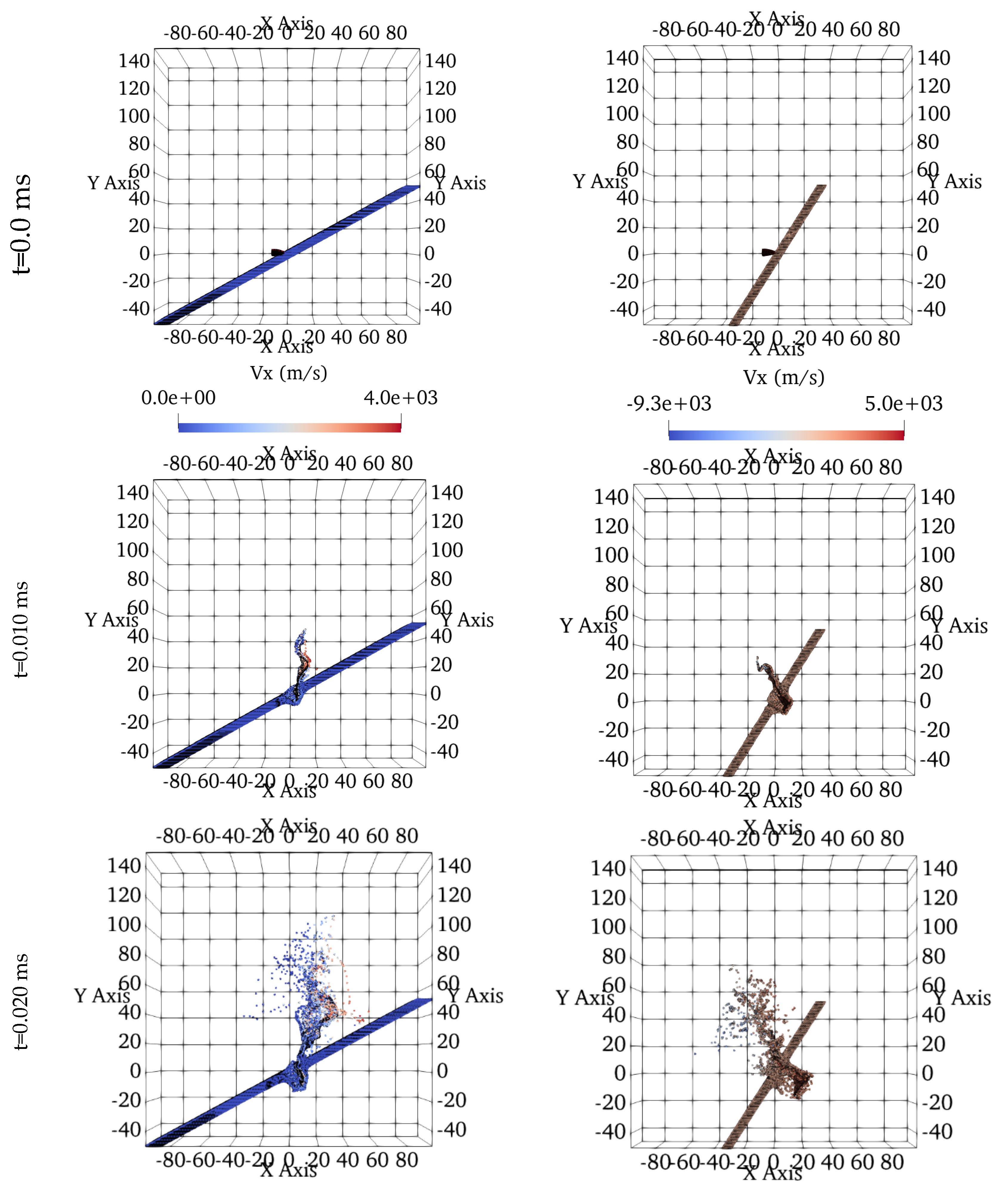
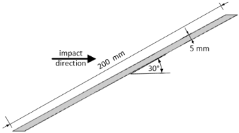
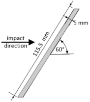
12]. We investigate the effects of oblique impact angles on the structural integrity and damage patterns of a target material subjected to high-speed projectile impacts. Specifically, we explore two distinct oblique impact scenarios: one with the target oriented at a 30° angle relative to the impact direction, and the other at a 60° angle. The projectile employed in both scenarios features an ogival shape, characterized by a pointed nose and streamlined geometry. The details of the projectile and target geometries are tabulated in
Table 3. The snapshots for the both impact scenarios are plotted at t=0.0, 10 and 30 μs and presented in
Figure 4.
Simulations were conducted using a projectile velocity of 4000 m/s along the x-direction, which represents typical hypervelocity conditions encountered in space structures. By analyzing the results of these simulations, the influence of impact angle and projectile geometry on penetration dynamics and resultant damage patterns was investigated.
The analysis of hypervelocity oblique impact simulations, particularly those focusing on 30° and 60° impact angles with an ogival projectile, revealed significant effects on impact dynamics and resulting damage patterns. The impact angle was found to be a key factor influencing the severity of the impact and the subsequent damage. Due to a shallower penetration angle, a 30° impact resulted in less damage compared to a 60° impact. This translates to variations in the extent and severity of damage observed in the target material. Furthermore, analysis of the damage patterns suggests distinct characteristics for the two scenarios. A 30° impact likely exhibits partial penetration with localized deformation and material ejection confined to the impact zone. In contrast, a 60° impact angle is resulted in a deeper penetration and more widespread fragmentation.
Additionally, the projectile shape plays a pivotal role in determining the penetration mechanics and resultant damage patterns. The ogival shape, characterized by a pointed nose and smooth curvature, enhances aerodynamic efficiency and kinetic energy transfer upon impact.
In the context of oblique impact scenarios, the formation of debris clouds reveals distinct dynamics between the 30° and 60° oblique angles. In the 30° impact scenario, the formation of the front face debris cloud is influenced by the relatively shallow penetration angle and that caused the gradual transfer of kinetic energy into the target material. Upon impact, the projectile imparts energy to the target material, causing localized deformation and material ejection primarily towards the impact direction. As a result, a front face debris cloud forms, consisting of fragmented material and ejecta propelled in the direction of the projectile trajectory. The size, velocity distribution, and spatial extent of the debris cloud are influenced by factors such as impact velocity, target material properties, and projectile geometry. On the contrary, in the 60° oblique scenario, a more pronounced transfer of kinetic energy and deeper penetration into the target material characterize the front face debris cloud formation. The steeper impact angle leads to increased energy deposition and rapid propagation of shock waves within the target material, causing extensive fragmentation. Consequently, the front face debris cloud exhibits greater dispersion, higher velocities, and broader spatial distribution compared to the 30° scenario.
Formation of the rear face debris cloud also varies between the two oblique impact scenarios. In the 30° scenario, the rear face debris cloud is more scattered in the upper right region, reflecting the shallower penetration angle. Notably, localized fragmentation and material ejection occur to a greater extent on the rear face compared to the front face. In contrast, the 60° oblique impact simulation displays a broader scattered region in the upper left area of the rear face and significant fragmentation.
4. Conclusions
This study presents a numerical method for simulating hypervelocity impacts of various shaped projectiles into metal targets and incorporates a rectangular prism target positioned at different oblique angles relative to the impact direction. Four distinct projectile shapes were investigated: square prism, triangular prism, truncated cone, and ogival. The simulations were performed using the open-source code MPM3D-F90 based on the Material Point Method (MPM). To enhance user-friendliness, a preprocessing tool was developed to simplify the definition of complex projectile and target geometries within the material domain. This tool allows users to define various projectile and target configurations, adjust their relative positions, and select symmetry boundary conditions and overall, one can easily customize impact scenarios based on their specific needs.
The investigation focuses on the influence of projectile shape and oblique impact angles on debris formation and target damage. The simulations reveal significant variations in debris cloud formation, propagation depending on the projectile geometry and impact angle, scattering behavior of ejected particles from both the target’s front and rear faces, and penetration depth. Sharp-nosed projectiles penetrat deeper, forming larger craters and causing more localized damage, while blunt shapes scatter debris more uniformly.
Overall, the presented framework offers a valuable tool for researchers to assess the risk of orbital debris impacting space structures. It could also be used to design and optimize shield systems for spacecraft protection against hypervelocity impacts encountered in space missions.
