Submitted:
07 June 2024
Posted:
10 June 2024
You are already at the latest version
Abstract
Keywords:
1. Introduction
2. Three-Member Transgenerator
2.1. Mathematical Model
2.1.1. Flux Linkage and Voltage Equations
2.1.2. Power and Torque Equations
2.2. Power Flow
3. Flywheel
3.1. Mechanical System Overview
3.2. Flywheel Charging Power and Storage Energy
3.3. Flywheel Power Management Strategies
- (1)
- Due to the acceleration, the speed change in the flywheel cannot be furnished immediately, delaying the power response to the demand. Therefore, changing the outer rotor torque is a better strategy.
- (2)
- To ensure the accuracy of the power control by controlling the outer rotor torque, the speed changes slightly in a short period, which requires the flywheel inertia referred to the outer rotor side to be significant.
- (3)
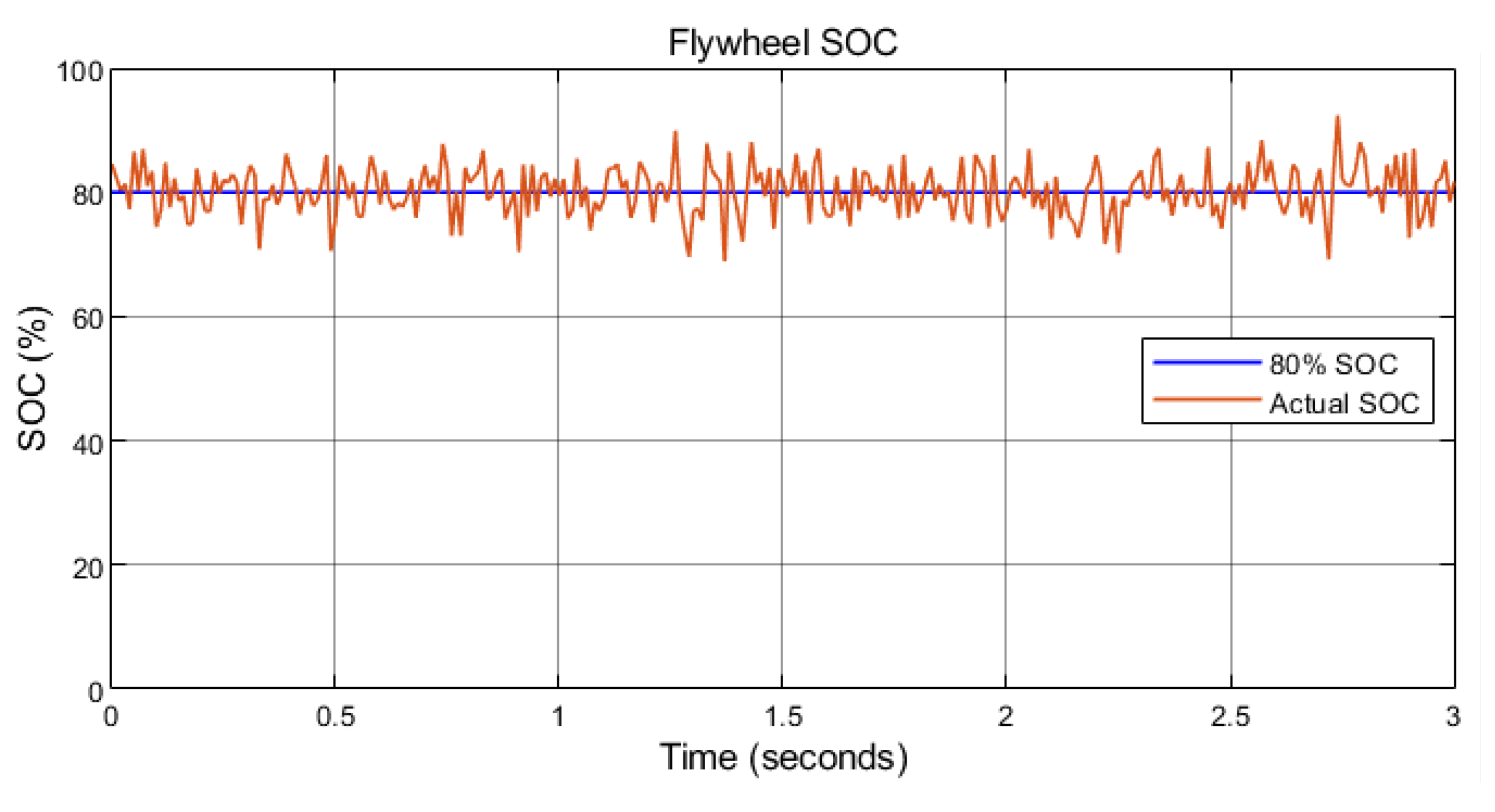
- Before the flywheel power management process, the flywheel should be accelerated to a state of charge (SOC) to ensure that the flywheel can release enough energy during emergencies. Besides, there should be a margin with the maximum storage to leave enough space for charging. The preset flywheel SOC in this paper is 80%, and then the flywheel speed will fluctuate (slightly most of the time) at around 80% SOC, as shown in Figure 10.
- (4)
- The performance of flywheel power response depends on the performance of the outer rotor torque control, which will be introduced later.
3.4. Flywheel Selection
3.4.1. Shape
3.4.2. Material
4. Control System
4.1. Rotor-Side Control
4.1.1. Inner Rotor Speed Control
4.1.2. Outer Rotor Torque Control
4.1.3. Rotor-Side Control Diagram

4.2. Grid-Side Control
5. Simulation and Verification
5.1. Simulink Modeling
5.2. Control System Verification
5.2.1. Set Up
- Outer rotor torque control
- Inner rotor speed control
- Grid-side control
5.2.2. Results
- Outer rotor torque control
- Inner rotor speed control
- Three-phase currents and voltage on the rotor side
- Grid-side control
- Three-phase current and voltage on the grid side
5.3. Flywheel Performance Evaluation
5.3.1. Set up
5.3.2. Results
6. Conclusion
References
- Tsao, Y.-C.; Vu, T.-L. Distributed energy storage system planning in relation to renewable energy investment. Renew. Energy 2023, 218. [Google Scholar] [CrossRef]
- C. Frischmann, J. P. C. Frischmann, J. P. Gouveia, and A. Horowitz, “Distributed Energy Storage @ projectdrawdown #climatesolutions,” Project Drawdown. https://drawdown.org/solutions/distributed-energy-storage.
- K. Fitton, “Storing renewable electricity on the grid of the future (updated for 2023),” Medium. https://medium.com/@kitfitton/storing-renewable-electricity-on-the-grid-of-the-future-updated-for-2023-1816484dc9cd.
- D. W. Gao, “Basic Concepts and Control Architecture of Microgrids,” in Energy Storage for Sustainable Microgrid, Denver, Colorado: University of Denver, 2015, pp.
- Suvire, G.O.; Molina, M.G.; Mercado, P.E. Improving the Integration of Wind Power Generation Into AC Microgrids Using Flywheel Energy Storage. IEEE Trans. Smart Grid 2012, 3, 1945–1954. [Google Scholar] [CrossRef]
- Mir, A.S.; Senroy, N. Intelligently Controlled Flywheel Storage for Enhanced Dynamic Performance. IEEE Trans. Sustain. Energy 2018, 10, 2163–2173. [Google Scholar] [CrossRef]
- Nair, S.G.; Senroy, N. Wind turbine with flywheel for improved power smoothening and LVRT. 2013 IEEE Power & Energy Society General Meeting. LOCATION OF CONFERENCE, CanadaDATE OF CONFERENCE; pp. 1–5.
- Díaz-González, F.; Sumper, A.; Gomis-Bellmunt, O.; Bianchi, F.D. Energy management of flywheel-based energy storage device for wind power smoothing. Appl. Energy 2013, 110, 207–219. [Google Scholar] [CrossRef]
- Li, X.; Palazzolo, A. A review of flywheel energy storage systems: state of the art and opportunities. J. Energy Storage 2021, 46, 103576. [Google Scholar] [CrossRef]
- M. G. Molina, “Distributed Energy Storage Systems for Applications in Future Smart Grids,” 2012 Sixth IEEE/PES Transmission and Distribution: Latin America Conference and Exposition (T& D-LA), Sep. 2012.
- Flywheel energy storage,” Wikipedia. https://en.wikipedia.org/wiki/Flywheel_energy storage.
- Mousavi G, S.M.; Faraji, F.; Majazi, A.; Al-Haddad, K. A comprehensive review of Flywheel Energy Storage System technology. Renew. Sustain. Energy Rev. 2017, 67, 477–490. [Google Scholar] [CrossRef]
- S. Sodhi, “Electromagnetic gearing applications in hybrid-electric vehicles,” Ph.D. thesis, Texas A&M University, 1994.
- L. Xu, “A new breed of electric machines - basic analysis and applications of dual mechanical port electric machines,” 2005 International Conference on Electrical Machines and Systems, 2005. [CrossRef]
- Cai, H.; Xu, L. Modeling and Control for Cage Rotor Dual Mechanical Port Electric Machine–Part I: Model Development. IEEE Trans. Energy Convers. 2015, 30, 957–965. [Google Scholar] [CrossRef]
- He, R.; Li, J. Optimized design and performance analysis of a magnetic-field modulated brushless dual-mechanical port motor with Halbach array permanent magnets. Adv. Mech. Eng. 2020, 12. [Google Scholar] [CrossRef]
- Chen, H.; El-Refaie, A.M.; Zuo, Y.; Cai, S.; Cao, L.; Lee, C.H.T. Comparative Study and Design Optimization of a Dual-Mechanical-Port Electric Machine for Hybrid Electric Vehicle Applications. IEEE Trans. Veh. Technol. 2022, 71, 8341–8353. [Google Scholar] [CrossRef]
- Jiang, M.; Niu, S. Overview of Dual Mechanical Port Machines in Transportation Electrification. IEEE Trans. Transp. Electrification 2023, PP, 1–1. [Google Scholar] [CrossRef]
- Y. Gao and M. Ehsani, “A mild hybrid vehicle drive train with a floating stator motor-configuration, control strategy, design and simulation verification,” SAE Technical Paper Series, 2002.
- H. Nasiri, A. Radan, A. Ghayebloo, and K. Ahi, “Dynamic modeling and simulation of transmotor based series-parallel HEV applied to Toyota Prius 2004,” 2011 10th International Conference on Environment and Electrical Engineering, 2011.
- Ershad, N.F.; Mehrjardi, R.T.; Ehsani, M. Electro-Mechanical EV Powertrain With Reduced Volt-Ampere Rating. IEEE Trans. Veh. Technol. 2018, 68, 224–233. [Google Scholar] [CrossRef]
- Ershad, N.F.; Mehrjardi, R.T.; Ehsani, M. Development of a Kinetic Energy Recovery System Using an Active Electromagnetic Slip Coupling. IEEE Trans. Transp. Electrification 2019, 5, 456–464. [Google Scholar] [CrossRef]
- Mehrjardi, R.T.; Ershad, N.F.; Ehsani, M. Transmotor-Based Powertrain for High-Performance Electric Vehicle. IEEE Trans. Transp. Electrification 2020, 6, 1199–1210. [Google Scholar] [CrossRef]
- Ershad, N.F.; Mehrjardi, R.T.; Ehsani, M. Efficient Flywheel-Based All-Wheel-Drive Electric Powertrain. IEEE Trans. Ind. Electron. 2020, 68, 5661–5671. [Google Scholar] [CrossRef]
- Sun, X.; Cheng, M.; Hua, W.; Xu, L. Optimal Design of Double-Layer Permanent Magnet Dual Mechanical Port Machine for Wind Power Application. IEEE Trans. Magn. 2009, 45, 4613–4616. [Google Scholar] [CrossRef]
- Sun, X.; Cheng, M. Thermal Analysis and Cooling System Design of Dual Mechanical Port Machine for Wind Power Application. IEEE Trans. Ind. Electron. 2012, 60, 1724–1733. [Google Scholar] [CrossRef]
- T. A. LIPO, “The d-q Equations of a Synchronous Machine,” in Analysis of Synchronous Machines, 2nd ed, Boca Raton, FL: CRC Press, 2012, pp. 168–169.
- Liu, J.; Gao, Y.; Geng, S.; Wu, L. Nonlinear Control of Variable Speed Wind Turbines via Fuzzy Techniques. IEEE Access 2016, 5, 27–34. [Google Scholar] [CrossRef]
- Metal Strength Chart: A detailed guide to metal strengths - eziil - best metal fabrication software,” Eziil. https://eziil.com/steel-strengths/.
- Kremer, G.O.; Chiu, M.-C.; Lin, C.-Y.; Gupta, S.; Claudio, D.; Thevenot, H. Application of axiomatic design, TRIZ, and mixed integer programming to develop innovative designs: a locomotive ballast arrangement case study. Int. J. Adv. Manuf. Technol. 2012, 61, 827–842. [Google Scholar] [CrossRef]
- Prasad, R.M.; Mulla, M.A. A Novel Position-Sensorless Algorithm for Field-Oriented Control of DFIG With Reduced Current Sensors. IEEE Trans. Sustain. Energy 2018, 10, 1098–1108. [Google Scholar] [CrossRef]


| Shape | Description | Moment of Inertia |
|---|---|---|
 |
Solid cylinder (or disk) of radius . | |
 |
Annular cylinder (or ring) of inner radius and outer radius . |
| Parameter | Value |
|---|---|
| Rated power | 2 MW |
| Blade radius | 50 m |
| Blade inertia | 6 × 10⁶ kg·m2 |
| Rated wind speed | 10 m/s |
| Air density | 1.225 kg/m3 |
| Parameter | Value |
|---|---|
| Rated stator voltage (line-to-line) | |
| Rated inner rotor voltage (line-to-line) | |
| 3 | |
| Stator to inner rotor turns ratio | 1:1 |
| 2.6 mH | |
| 0.1 mH | |
| 0.1 mH | |
| 1.5 × 10⁻³ Ω | |
| 1.2 × 10⁻³ Ω | |
| Parameters | Value |
|---|---|
| 3000 kg·m2 | |
| 32000 kg·m2 | |
| Rated Inner rotor torque | 32739 N·m |
| Rated Outer rotor torque | 5300 N·m |
| 45 | |
| 10 |
| Parameters | Type/Value |
|---|---|
| Shape | Ring |
| Material | Steel |
| Density | 7850 kg/m3 |
| 0.5 m | |
| 0.6 m | |
| 0.3624 m | |
| Mass | 983.7 kg |
| 300 kg·m2 |
| Parameters | Value |
|---|---|
| Outer rotor speed limit | 125 rad/s |
| Flywheel speed limit | 1250 rad/s (11937 rpm) |
| Storage capacity | 65.1 kWh |
Disclaimer/Publisher’s Note: The statements, opinions and data contained in all publications are solely those of the individual author(s) and contributor(s) and not of MDPI and/or the editor(s). MDPI and/or the editor(s) disclaim responsibility for any injury to people or property resulting from any ideas, methods, instructions or products referred to in the content. |
© 2024 by the authors. Licensee MDPI, Basel, Switzerland. This article is an open access article distributed under the terms and conditions of the Creative Commons Attribution (CC BY) license (http://creativecommons.org/licenses/by/4.0/).


