Submitted:
10 June 2024
Posted:
11 June 2024
You are already at the latest version
Abstract
Keywords:
1. Introduction
- A-FMR. The main mechanism is represented by annular dysfunction/dilatation and atriogenic leaflet tethering with reduced leaflet remodeling, leading to an annulus-leaflet area imbalance. It usually involves patients with preserved left ventricular (LV) systolic function, especially if they are affected by atrial fibrillation (AF) [7,8]. Optimal treatment remains debated and includes rhythm control, different transcatheter and surgical procedures, with the latter potentially able to treat all the mechanism of the disease: plication for left atrium (LA) enlargement, annuloplasty for annulus dilatation, patch augmentation for insufficient leaflet remodeling and Cox-Maze procedure for AF [9,10]. When feasible, MVr is probably associated to a better outcome than MVR [11].
- V-FMR. The main mechanism is LV dilatation and/or systolic dysfunction with global or regional remodeling of LV and/or asynchrony, leading to symmetric or asymmetric tethering of mitral leaflets. The best treatment usually involves a comprehensive use of the “classical” heart failure management strategies: optimal medical treatment, myocardial revascularization if indicated, cardiac resynchronization therapy, transcatheter edge-to-edge repair (TEER) [12].
2. Materials and Methods
3. Transcatheter Mitral Valve Intervention
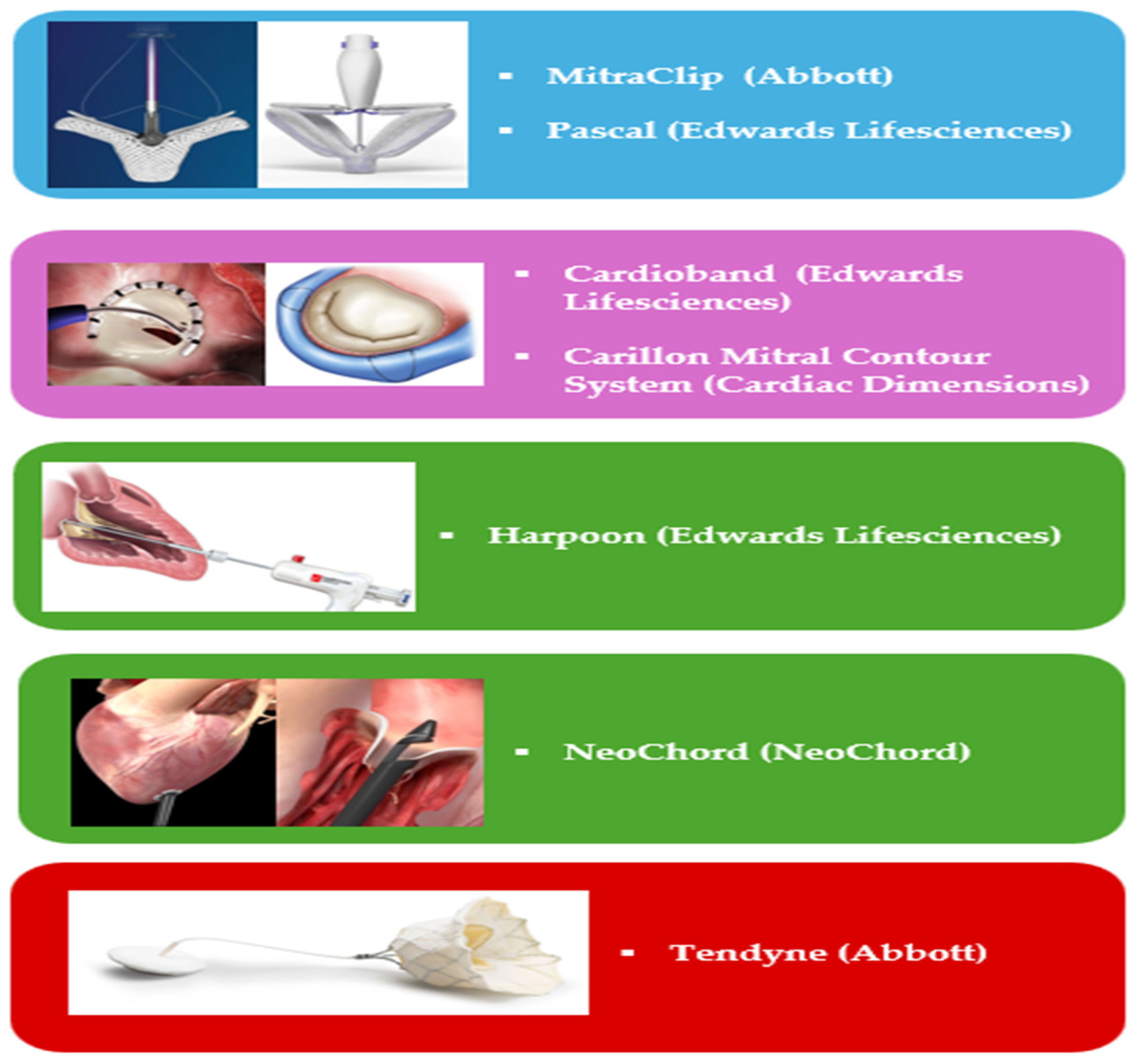
- -
- Leaflet’s approximation: MitraClip (Abbott Cardiovascular, Plymouth, MN, USA), PASCAL (Edwards Lifesciences, Irvine, CA, USA);
- -
- Direct Annuloplasty: Cardioband (Edwards Lifesciences, Irvine, CA, USA);
- -
- Indirect Annuloplasty: Carillon Mitral Contour System (Cardiac Dimensions, Washington DC, USA);
- -
- Chordal Repair: HARPOON (Edwards Lifesciences, Irvine, CA, USA). NeoChord (NeoChord Inc. Louise Park, MN, USA).
- Vi-V: this approach encompasses the implantation of a new bioprosthesis within a degenerated mitral bioprosthesis and is the most used out of the three. It is feasible via both TS and TA approaches. ViV procedures have demonstrated excellent results in terms of procedural (74%) and technical (94.4%) success rates, with a low incidence of post-procedural adverse events: 2.2% significant left ventricular outflow obstruction (LVOTO), less than 1% conversion to surgery, 3.3% significant paravalvular leak (PVL), and 6.2% 30-day mortality.
- Vi-R: it is based on the implantation of a bioprosthesis following a failed mitral valve annuloplasty. The procedural success rate (57.4%) is lower compared to ViV procedures, with an increased risk of adverse events: 5% LVOTO, 12.6% PVL, 12% requiring a second valve implantation, and 9.9% 30-day mortality. The higher incidence of peri-procedural complications, along with significant residual MR, partly accounts for this elevated mortality rate. It is noteworthy that in patients previously subjected to MVr with annuloplasty ring, TEER should be prioritized as the first option [35].
- Vi-MAC: This procedure poses significant technical challenges and is associated with a high-risk profile in the target population. Procedural success rates are comparatively lower (41.4%), with a higher incidence of complications: 8.6% conversion to surgery, 39.7% LVOTO, 6.9% valve embolization, 13% significant residual MR, 34.5% 30-day mortality, and over 60% 1-year mortality. Due to these complexities and risks, Vi-MAC procedures are considered the most challenging among the various TMVR approaches.
4. Pre-Procedural Evaluation
4.a Transcatether Edge-to-Edge Repair
4.b Indirect and Direct Annuloplasty
4.c Chordal Repair
- “Type A” (isolated central posterior prolapse/flail),
- “Type B” (posterior multi-scallop prolapse/flail),
- “Type C” (anterior or bileaflet prolapse/flail)
- “Type D” (paracommissural prolapse/flail or any significant annular or leaflet disease, e.g., calcification).
4.e TMVR
5. Intra-Procedural Guidance
5.a Transcatether Edge-to-Edge Repair
- (1)
- TSP and SGC advancement,
- (2)
- Straddling and steering of the device,
- (3)
- Orientation,
- (4)
- Grasping
- (5)
- Final evaluation and release.
5.b Indirect Annuloplasty
5.c Direct Annuloplasty
5.d Chordal Repair
5.e TMVR
6. Post-Procedural Evaluation
6.a TEER
6.b Annuloplasty Devices
6.c Chordal Repair
6.d TMVR
7. Emerging Techniques and Potential Future Directions
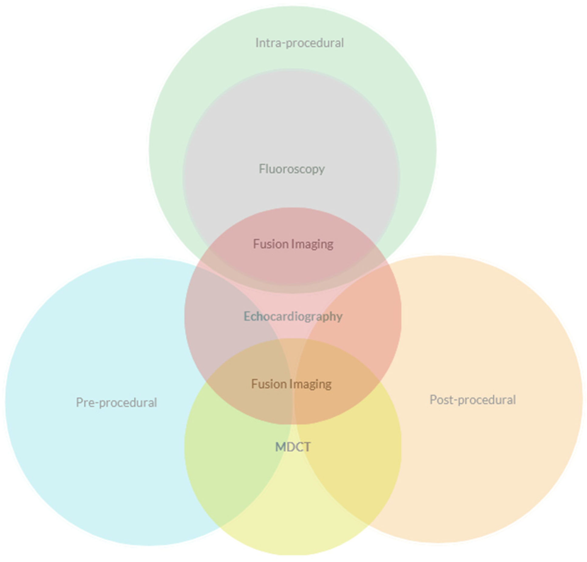
8. Conclusions
Author Contributions
Funding
Institutional Review Board Statement
Conflicts of Interest
Abbreviations
| AI | Artificial Intelligence |
| ASD | Atrial septal defect |
| AV | Atrio-ventricular |
| cMDCT | Contrast multidetector computed tomography |
| CS | Coronary sinus |
| FMR | Functional mitral regurgitation |
| GCV | Great cardiac vein |
| IAS | Interatrial septum |
| IE | Interventional Echocardiographer |
| LA | Left atrium, left atrial |
| LCA | Left circumflex artery |
| LV | Left ventricle, left ventricular |
| LVOT | Left ventricular outflow |
| LVOTO | Left ventricular outflow obstruction |
| MA | Mitral annulus |
| MR | Mitral regurgitation |
| PMR | Primary mitral regurgitation |
| PVL | Paravalvular leak |
| PWD | Pulsed-wave doppler |
| RAE | Radiation exposure |
| SHD | Structural heart disease |
| TEE | Transesophageal Echocardiography |
| TEER | Transcatheter edge-to-edge repair |
| TMVI | Transcatheter mitral valve intervention |
| TMVr | Transcatheter mitral valve repair |
| TMVR | Transcatheter mitral valve replacement |
| TR | Tricuspid regurgitation |
| Vi-MAC | Valve in MAC |
| Vi-R | Valve in ring |
| Vi-V | Valve in valve |
| VR | Virtual reality |
| WMAs | Wall motion abnormalities |
References
- Nkomo VT, Gardin JM, Skelton TN, Gottdiener JS, Scott CG, Enriquez-Sarano M. Burden of valvular heart diseases: a population-based study. Lancet. 2006 Sep 16;368(9540):1005-11. [CrossRef] [PubMed]
- Agricola E, Ielasi A, Oppizzi M, Faggiano P, Ferri L, Calabrese A, Vizzardi E, Alfieri O, Margonato A. Long-term prognosis of medically treated patients with functional mitral regurgitation and left ventricular dysfunction. Eur J Heart Fail. 2009 Jun;11(6):581-7. Epub 2009 Apr 27. [CrossRef] [PubMed]
- Tribouilloy C, Rusinaru D, Grigioni F, Michelena HI, Vanoverschelde JL, Avierinos JF, Barbieri A, Pislaru SV, Russo A, Pasquet A, Théron A, Szymanski C, Lévy F, Enriquez-Sarano M; Mitral Regurgitation International Database (MIDA) Investigators. Long-term mortality associated with left ventricular dysfunction in mitral regurgitation due to flail leaflets: a multicenter analysis. Circ Cardiovasc Imaging. 2014 Mar;7(2):363-70. Epub 2013 Dec 20. [CrossRef] [PubMed]
- Chaput M, Handschumacher MD, Tournoux F, Hua L, Guerrero JL, Vlahakes GJ, Levine RA. Mitral leaflet adaptation to ventricular remodeling: occurrence and adequacy in patients with functional mitral regurgitation. Circulation. 2008 Aug 19;118(8):845-52. Epub 2008 Aug 4. [CrossRef] [PubMed]
- Sannino A, Smith RL 2nd, Schiattarella GG, Trimarco B, Esposito G, Grayburn PA. Survival and Cardiovascular Outcomes of Patients With Secondary Mitral Regurgitation: A Systematic Review and Meta-analysis. JAMA Cardiol. 2017 Oct 1;2(10):1130-1139. [CrossRef] [PubMed]
- Okamoto C, Okada A, Nishimura K, Moriuchi K, Amano M, Takahama H, Amaki M, Hasegawa T, Kanzaki H, Fujita T, Kobayashi J, Yasuda S, Izumi C. Prognostic comparison of atrial and ventricular functional mitral regurgitation. Open Heart. 2021 Feb;8(1):e001574. [CrossRef] [PubMed]
- Silbiger, J.J. Novel pathogenetic mechanisms and structural adaptations in ischemic mitral regurgitation. J Am Soc Echocardiogr. 2013 Oct;26(10):1107-1117. Epub 2013 Aug 14. [CrossRef] [PubMed]
- Deferm S, Bertrand PB, Verbrugge FH, Verhaert D, Rega F, Thomas JD, Vandervoort PM. Atrial Functional Mitral Regurgitation: JACC Review Topic of the Week. J Am Coll Cardiol. 2019 May 21;73(19):2465-2476. [CrossRef] [PubMed]
- Farhan S, Silbiger JJ, Halperin JL, Zhang L, Dukkipati SR, Vogel B, Kini A, Sharma S, Lerakis S. Pathophysiology, Echocardiographic Diagnosis, and Treatment of Atrial Functional Mitral Regurgitation: JACC State-of-the-Art Review. J Am Coll Cardiol. 2022 Dec 13;80(24):2314-2330. Erratum in: J Am Coll Cardiol. 2023 Feb 21;81(7):711. [CrossRef] [PubMed]
- Aranda-Domene R, Canovas SJ. Going further of mitral ring annuloplasty: the role of surgery in atrial functional mitral regurgitation. J Thorac Dis. 2023 May 30;15(5):2381-2384. Epub 2023 Apr 11. [CrossRef] [PubMed]
- Hirji SA, Cote CL, Javadikasgari H, Malarczyk A, McGurk S, Kaneko T. Atrial functional versus ventricular functional mitral regurgitation: Prognostic implications. J Thorac Cardiovasc Surg. 2022 Dec;164(6):1808-1815.e4. Epub 2020 Dec 31. [CrossRef] [PubMed]
- Alec Vahanian, Friedhelm Beyersdorf, Fabien Praz, Milan Milojevic, Stephan Baldus, Johann Bauersachs, Davide Capodanno, Lenard Conradi, Michele De Bonis, Ruggero De Paulis, Victoria Delgado, Nick Freemantle, Martine Gilard, Kristina H Haugaa, Anders Jeppsson, Peter Jüni, Luc Pierard, Bernard D Prendergast, J Rafael Sádaba, Christophe Tribouilloy, Wojtek Wojakowski, ESC/EACTS Scientific Document Group, ESC National Cardiac Societies, 2021 ESC/EACTS Guidelines for the management of valvular heart disease: Developed by the Task Force for the management of valvular heart disease of the European Society of Cardiology (ESC) and the European Association for Cardio-Thoracic Surgery (EACTS), European Heart Journal, Volume 43, Issue 7, 14 February 2022, Pages 561–632. [CrossRef]
- Mirabel M, Iung B, Baron G, Messika-Zeitoun D, Détaint D, Vanoverschelde JL, Butchart EG, Ravaud P, Vahanian A. What are the characteristics of patients with severe, symptomatic, mitral regurgitation who are denied surgery? Eur Heart J. 2007 Jun;28(11):1358-65. Epub 2007 Mar 9. [CrossRef] [PubMed]
- Feldman T, Kar S, Rinaldi M, Fail P, Hermiller J, Smalling R, Whitlow PL, Gray W, Low R, Herrmann HC, Lim S, Foster E, Glower D; EVEREST Investigators. Percutaneous mitral repair with the MitraClip system: safety and midterm durability in the initial EVEREST (Endovascular Valve Edge-to-Edge REpair Study) cohort. J Am Coll Cardiol. 2009 Aug 18;54(8):686-94. [CrossRef] [PubMed]
- Feldman T, Kar S, Elmariah S, Smart SC, Trento A, Siegel RJ, Apruzzese P, Fail P, Rinaldi MJ, Smalling RW, Hermiller JB, Heimansohn D, Gray WA, Grayburn PA, Mack MJ, Lim DS, Ailawadi G, Herrmann HC, Acker MA, Silvestry FE, Foster E, Wang A, Glower DD, Mauri L; EVEREST II Investigators. Randomized Comparison of Percutaneous Repair and Surgery for Mitral Regurgitation: 5-Year Results of EVEREST II. J Am Coll Cardiol. 2015 Dec 29;66(25):2844-2854. [CrossRef] [PubMed]
- Obadia JF, Messika-Zeitoun D, Leurent G, Iung B, Bonnet G, Piriou N, Lefèvre T, Piot C, Rouleau F, Carrié D, Nejjari M, Ohlmann P, Leclercq F, Saint Etienne C, Teiger E, Leroux L, Karam N, Michel N, Gilard M, Donal E, Trochu JN, Cormier B, Armoiry X, Boutitie F, Maucort-Boulch D, Barnel C, Samson G, Guerin P, Vahanian A, Mewton N; MITRA-FR Investigators. Percutaneous Repair or Medical Treatment for Secondary Mitral Regurgitation. N Engl J Med. 2018 Dec 13;379(24):2297-2306. Epub 2018 Aug 27. [CrossRef] [PubMed]
- Stone GW, Abraham WT, Lindenfeld J, Kar S, Grayburn PA, Lim DS, Mishell JM, Whisenant B, Rinaldi M, Kapadia SR, Rajagopal V, Sarembock IJ, Brieke A, Marx SO, Cohen DJ, Asch FM, Mack MJ; COAPT Investigators. Five-Year Follow-up after Transcatheter Repair of Secondary Mitral Regurgitation. N Engl J Med. 2023 Jun 1;388(22):2037-2048. Epub 2023 Mar 5. [CrossRef] [PubMed]
- Doldi PM, Stolz L, Kalbacher D, Köll B, Geyer M, Ludwig S, Orban M, Braun D, Weckbach LT, Stocker TJ, Näbauer M, Higuchi S, Ruf T, Da Rocha E Silva J, Wild M, Tence N, Unterhuber M, Schofer N, Petrescu A, Thiele H, Lurz P, Lubos E, von Bardeleben S, Karam N, Samim D, Paradis JM, Iliadis C, Xhepa E, Hagl C, Massberg S, Hausleiter J; EuroSMR and PRIME-MR Investigators. Right ventricular dysfunction predicts outcome after transcatheter mitral valve repair for primary mitral valve regurgitation. Eur J Heart Fail. 2022 Nov;24(11):2162-2171. Epub 2022 Sep 15. [CrossRef] [PubMed]
- Karam N, Stolz L, Orban M, Deseive S, Praz F, Kalbacher D, Westermann D, Braun D, Näbauer M, Neuss M, Butter C, Kassar M, Petrescu A, Pfister R, Iliadis C, Unterhuber M, Park SD, Thiele H, Baldus S, von Bardeleben RS, Blankenberg S, Massberg S, Windecker S, Lurz P, Hausleiter J. Impact of Right Ventricular Dysfunction on Outcomes After Transcatheter Edge-to-Edge Repair for Secondary Mitral Regurgitation. JACC Cardiovasc Imaging. 2021 Apr;14(4):768-778. Epub 2021 Feb 10. [CrossRef] [PubMed]
- Shechter A, Vaturi M, Kaewkes D, Koren O, Koseki K, Solanki A, Natanzon SS, Patel V, Skaf S, Makar M, Chakravarty T, Makkar RR, Siegel RJ. Prognostic Value of Baseline Tricuspid Annular Plane Systolic Excursion to Pulmonary Artery Systolic Pressure Ratio in Mitral Transcatheter Edge-to-Edge Repair. J Am Soc Echocardiogr. 2023 Apr;36(4):391-401.e19. Epub 2023 Jan 16. [CrossRef] [PubMed]
- Szerlip M, Spargias KS, Makkar R, Kar S, Kipperman RM, O’Neill WW, Ng MKC, Smith RL, Fam NP, Rinaldi MJ, Raffel OC, Walters DL, Levisay J, Montorfano M, Latib A, Carroll JD, Nickenig G, Windecker S, Marcoff L, Cohen GN, Schäfer U, Webb JG, Lim DS. 2-Year Outcomes for Transcatheter Repair in Patients With Mitral Regurgitation From the CLASP Study. JACC Cardiovasc Interv. 2021 Jul 26;14(14):1538-1548. Epub 2021 May 18. Erratum in: JACC Cardiovasc Interv. 2022 Jul 11;15(13):1395. [CrossRef] [PubMed]
- Zahr F, Smith RL, Gillam LD, Chadderdon S, Makkar R, von Bardeleben RS, Ruf TF, Kipperman RM, Rassi AN, Szerlip M, Goldman S, Inglessis-Azuaje I, Yadav P, Lurz P, Davidson CJ, Mumtaz M, Gada H, Kar S, Kodali SK, Laham R, Hiesinger W, Fam NP, Keßler M, O’Neill WW, Whisenant B, Kliger C, Kapadia S, Rudolph V, Choo J, Hermiller J, Morse MA, Schofer N, Gafoor S, Latib A, Mahoney P, Kaneko T, Shah PB, Riddick JA, Muhammad KI, Boekstegers P, Price MJ, Praz F, Koulogiannis K, Marcoff L, Hausleiter J, Lim DS; CLASP IID Pivotal Trial Investigators. One-Year Outcomes From the CLASP IID Randomized Trial for Degenerative Mitral Regurgitation. JACC Cardiovasc Interv. 2023 Oct 26:S1936-8798(23)01358-4. Epub ahead of print. [CrossRef] [PubMed]
- Schofer J, Siminiak T, Haude M, Herrman JP, Vainer J, Wu JC, Levy WC, Mauri L, Feldman T, Kwong RY, Kaye DM, Duffy SJ, Tübler T, Degen H, Brandt MC, Van Bibber R, Goldberg S, Reuter DG, Hoppe UC. Percutaneous mitral annuloplasty for functional mitral regurgitation: results of the CARILLON Mitral Annuloplasty Device European Union Study. Circulation. 2009 Jul 28;120(4):326-33. Epub 2009 Jul 13. [CrossRef] [PubMed]
- Siminiak T, Wu JC, Haude M, Hoppe UC, Sadowski J, Lipiecki J, Fajadet J, Shah AM, Feldman T, Kaye DM, Goldberg SL, Levy WC, Solomon SD, Reuter DG. Treatment of functional mitral regurgitation by percutaneous annuloplasty: results of the TITAN Trial. Eur J Heart Fail. 2012 Aug;14(8):931-8. Epub 2012 May 21. [CrossRef] [PubMed]
- Lipiecki J, Siminiak T, Sievert H, Müller-Ehmsen J, Degen H, Wu JC, Schandrin C, Kalmucki P, Hofmann I, Reuter D, Goldberg SL, Haude M. Coronary sinus-based percutaneous annuloplasty as treatment for functional mitral regurgitation: the TITAN II trial. Open Heart. 2016 Jul 8;3(2):e000411. [CrossRef] [PubMed]
- Witte KK, Lipiecki J, Siminiak T, Meredith IT, Malkin CJ, Goldberg SL, Stark MA, von Bardeleben RS, Cremer PC, Jaber WA, Celermajer DS, Kaye DM, Sievert H. The REDUCE FMR Trial: A Randomized Sham-Controlled Study of Percutaneous Mitral Annuloplasty in Functional Mitral Regurgitation. JACC Heart Fail. 2019 Nov;7(11):945-955. Epub 2019 Sep 11. [CrossRef] [PubMed]
- Lipiecki J, Kaye DM, Witte KK, Haude M, Kapadia S, Sievert H, Goldberg SL, Levy WC, Siminiak T. Long-Term Survival Following Transcatheter Mitral Valve Repair: Pooled Analysis of Prospective Trials with the Carillon Device. Cardiovasc Revasc Med. 2020 Jun;21(6):712-716. Epub 2020 Feb 25. [CrossRef] [PubMed]
- Messika-Zeitoun D, Nickenig G, Latib A, Kuck KH, Baldus S, Schueler R, La Canna G, Agricola E, Kreidel F, Huntgeburth M, Zuber M, Verta P, Grayburn P, Vahanian A, Maisano F. Transcatheter mitral valve repair for functional mitral regurgitation using the Cardioband system: 1 year outcomes. Eur Heart J. 2019 Feb 1;40(5):466-472. [CrossRef] [PubMed]
- Hegeman RMJJ, Gheorghe LL, de Kroon TL, van Putte BP, Swaans MJ, Klein P. State-of-the-Art Review: Technical and Imaging Considerations in Novel Transapical and Port-Access Mitral Valve Chordal Repair for Degenerative Mitral Regurgitation. Front Cardiovasc Med. 2022 Apr 12;9:850700. [CrossRef] [PubMed]
- Colli A, Zucchetta F, Kliger C, Bellu R, Francone M, Sedati P, Jelnin V, Ruiz CE, Manzan E, Besola L, Bizzotto E, Gerosa G. CT for the Transapical Off-Pump Mitral Valve Repair With Neochord Implantation Procedure. JACC Cardiovasc Imaging. 2017 Nov;10(11):1397-1400. Epub 2017 May 17. [CrossRef] [PubMed]
- Colli A, Bizzotto E, Manzan E, Besola L, Pradegan N, Bellu R, Pittarello D, Gerosa G. Patient-Specific Ventricular Access Site Selection for the NeoChord Mitral Valve Repair Procedure. Ann Thorac Surg. 2017 Aug;104(2):e199-e202. [CrossRef] [PubMed]
- Seeburger J, Rinaldi M, Nielsen SL, Salizzoni S, Lange R, Schoenburg M, Alfieri O, Borger MA, Mohr FW, Aidietis A. Off-pump transapical implantation of artificial neo-chordae to correct mitral regurgitation: the TACT Trial (Transapical Artificial Chordae Tendinae) proof of concept. J Am Coll Cardiol. 2014 Mar 11;63(9):914-9. Epub 2013 Sep 24. [CrossRef] [PubMed]
- Gammie JS, Bartus K, Gackowski A, Szymanski P, Bilewska A, Kusmierczyk M, Kapelak B, Rzucidlo-Resil J, Duncan A, Yadav R, Livesey S, Diprose P, Gerosa G, D’Onofrio A, Pittarello D, Denti P, La Canna G, De Bonis M, Alfieri O, Hung J, Kolsut P, D’Ambra MN. Safety and performance of a novel transventricular beating heart mitral valve repair system: 1-year outcomes. Eur J Cardiothorac Surg. 2021 Jan 4;59(1):199-206. [CrossRef] [PubMed]
- Maisano F, Taramasso M. Mitral valve-in-valve, valve-in-ring, and valve-in-MAC: the Good, the Bad, and the Ugly. Eur Heart J. 2019 Feb 1;40(5):452-455. [CrossRef] [PubMed]
- Singh GD, Smith TW, Boyd WD, Rogers JH. Clipping the Ring: Transcatheter Edge-to-Ring Mitral Valve Repair in a Patient With Prior Mitral Annuloplasty Ring. JACC Cardiovasc Interv. 2018 Apr 9;11(7):e55-e58. Epub 2018 Jan 17. [CrossRef] [PubMed]
- Sorajja P, Gössl M, Babaliaros V, Rizik D, Conradi L, Bae R, Burke RF, Schäfer U, Lisko JC, Riley RD, Guyton R, Dumonteil N, Berthoumieu P, Tchetche D, Blanke P, Cavalcante JL, Sun B. Novel Transcatheter Mitral Valve Prosthesis for Patients With Severe Mitral Annular Calcification. J Am Coll Cardiol. 2019 Sep 17;74(11):1431-1440. [CrossRef] [PubMed]
- Sorajja P, Moat N, Badhwar V, Walters D, Paone G, Bethea B, Bae R, Dahle G, Mumtaz M, Grayburn P, Kapadia S, Babaliaros V, Guerrero M, Satler L, Thourani V, Bedogni F, Rizik D, Denti P, Dumonteil N, Modine T, Sinhal A, Chuang ML, Popma JJ, Blanke P, Leipsic J, Muller D. Initial Feasibility Study of a New Transcatheter Mitral Prosthesis: The First 100 Patients. J Am Coll Cardiol. 2019 Mar 26;73(11):1250-1260. [CrossRef] [PubMed]
- Zoghbi WA, Adams D, Bonow RO, Enriquez-Sarano M, Foster E, Grayburn PA, Hahn RT, Han Y, Hung J, Lang RM, Little SH, Shah DJ, Shernan S, Thavendiranathan P, Thomas JD, Weissman NJ. Recommendations for Noninvasive Evaluation of Native Valvular Regurgitation: A Report from the American Society of Echocardiography Developed in Collaboration with the Society for Cardiovascular Magnetic Resonance. J Am Soc Echocardiogr. 2017 Apr;30(4):303-371. Epub 2017 Mar 14. [CrossRef] [PubMed]
- Lancellotti P, Pibarot P, Chambers J, La Canna G, Pepi M, Dulgheru R, Dweck M, Delgado V, Garbi M, Vannan MA, Montaigne D, Badano L, Maurovich-Horvat P, Pontone G, Vahanian A, Donal E, Cosyns B; Scientific Document Committee of the European Association of Cardiovascular Imaging. Multi-modality imaging assessment of native valvular regurgitation: an EACVI and ESC council of valvular heart disease position paper. Eur Heart J Cardiovasc Imaging. 2022 Apr 18;23(5):e171-e232. [CrossRef] [PubMed]
- Kahlert P, Plicht B, Schenk IM, Janosi RA, Erbel R, Buck T. Direct assessment of size and shape of noncircular vena contracta area in functional versus organic mitral regurgitation using real-time three-dimensional echocardiography. J Am Soc Echocardiogr. 2008 Aug;21(8):912-21. Epub 2008 Apr 2. [CrossRef] [PubMed]
- Fiore G, Ingallina G, Ancona F, Gaspardone C, Biondi F, Margonato D, Morosato M, Belli M, Tavernese A, Stella S, Agricola E. Quantification of Mitral Regurgitation in Mitral Valve Prolapse by Three-Dimensional Vena Contracta Area: Derived Cutoff Values and Comparison With Two-Dimensional Multiparametric Approach. J Am Soc Echocardiogr. 2024 Mar 24:S0894-7317(24)00116-0. Epub ahead of print. [CrossRef] [PubMed]
- Hundley WG, Kizilbash AM, Afridi I, Franco F, Peshock RM, Grayburn PA. Administration of an intravenous perfluorocarbon contrast agent improves echocardiographic determination of left ventricular volumes and ejection fraction: comparison with cine magnetic resonance imaging. J Am Coll Cardiol. 1998 Nov;32(5):1426-32. [CrossRef] [PubMed]
- Barletta V, Hinojar R, Carbonell A, González-Gómez A, Fabiani I, Di Bello V, Jiménez-Nacher JJ, Zamorano J, Fernández-Golfín C. Three-dimensional full automated software in the evaluation of the left ventricle function: from theory to clinical practice. Int J Cardiovasc Imaging. 2018 Aug;34(8):1205-1213. Epub 2018 Mar 31. [CrossRef] [PubMed]
- Hausleiter J, Stocker TJ, Adamo M, Karam N, Swaans MJ, Praz F. Mitral valve transcatheter edge-to-edge repair. EuroIntervention. 2023 Jan 23;18(12):957-976. [CrossRef] [PubMed]
- Agricola E, Ancona F, Bartel T, Brochet E, Dweck M, Faletra F, Lancellotti P, Mahmoud-Elsayed H, Marsan NA, Maurovich-Hovart P, Monaghan M, Pontone G, Sade LE, Swaans M, Von Bardeleben RS, Wunderlich N, Zamorano JL, Popescu BA, Cosyns B, Donal E. Multimodality imaging for patient selection, procedural guidance, and follow-up of transcatheter interventions for structural heart disease: a consensus document of the EACVI Task Force on Interventional Cardiovascular Imaging: part 1: access routes, transcatheter aortic valve implantation, and transcatheter mitral valve interventions. Eur Heart J Cardiovasc Imaging. 2023 Aug 23;24(9):e209-e268. [CrossRef] [PubMed]
- Lesevic H, Karl M, Braun D, Barthel P, Orban M, Pache J, Hadamitzky M, Mehilli J, Stecher L, Massberg S, Ott I, Schunkert H, Kastrati A, Sonne C, Hausleiter J. Long-Term Outcomes After MitraClip Implantation According to the Presence or Absence of EVEREST Inclusion Criteria. Am J Cardiol. 2017 Apr 15;119(8):1255-1261. Epub 2017 Jan 25. [CrossRef] [PubMed]
- Praz F, Windecker S, Kapadia S. PASCAL: A New Addition to the Armamentarium of Transcatheter Repair Systems for Mitral Leaflet Approximation. JACC Cardiovasc Interv. 2019 Jul 22;12(14):1379-1381. Epub 2019 Jun 26. [CrossRef] [PubMed]
- Koell B, Orban M, Weimann J, Kassar M, Karam N, Neuss M, Petrescu A, Iliadis C, Unterhuber M, Adamo M, Giannini C, Melica B, Ludwig S, Massberg S, Praz F, Pfister R, Thiele H, Stephan von Bardeleben R, Baldus S, Butter C, Lurz P, Windecker S, Metra M, Petronio AS, Hausleiter J, Lubos E, Kalbacher D; EuroSMR Investigators. Outcomes Stratified by Adapted Inclusion Criteria After Mitral Edge-to-Edge Repair. J Am Coll Cardiol. 2021 Dec 14;78(24):2408-2421. [CrossRef] [PubMed]
- Piroli F, Boccellino A, Ingallina G, Rolando M, Melillo F, Ancona F, Stella S, Biondi F, Palmisano A, Esposito A, Denti P, Montorfano M, Maisano F, Castiglioni A, Agricola E. Feasibility and reliability of comprehensive three-dimensional transoesophageal echocardiography screening process for transcatheter mitral valve replacement. Eur Heart J Cardiovasc Imaging. 2023 Jul 24;24(8):1043-1051. [CrossRef] [PubMed]
- Kim JH, Kim EY, Jin GY, Choi JB. A Review of the Use of Cardiac Computed Tomography for Evaluating the Mitral Valve before and after Mitral Valve Repair. Korean J Radiol. 2017 Sep-Oct;18(5):773-785. Epub 2017 Jul 17. [CrossRef] [PubMed]
- Koo HJ, Yang DH, Oh SY, Kang JW, Kim DH, Song JK, Lee JW, Chung CH, Lim TH. Demonstration of mitral valve prolapse with CT for planning of mitral valve repair. Radiographics. 2014 Oct;34(6):1537-52. [CrossRef] [PubMed]
- Kishimoto N, Takahashi Y, Fujii H, Sakon Y, Izuta S, Kitada R, Morisaki A, Yoshida H, Ehara S, Shibata T. Computed tomography to identify risk factors for left circumflex artery injury during mitral surgery. Eur J Cardiothorac Surg. 2022 Feb 18;61(3):675-683. [CrossRef] [PubMed]
- Feirer N, Kornyeva A, Lang M, Sideris K, Voss B, Krane M, Lange R, Vitanova K. Non-robotic minimally invasive mitral valve repair: a 20-year single-centre experience. Eur J Cardiothorac Surg. 2022 Oct 4;62(5):ezac223. [CrossRef] [PubMed]
- Bergonzoni E, D’Onofrio A, Mastro F, Gerosa G. Microinvasive mitral valve repair with transapical mitral neochordae implantation. Front Cardiovasc Med. 2023 Jul 28;10:1166892. [CrossRef] [PubMed]
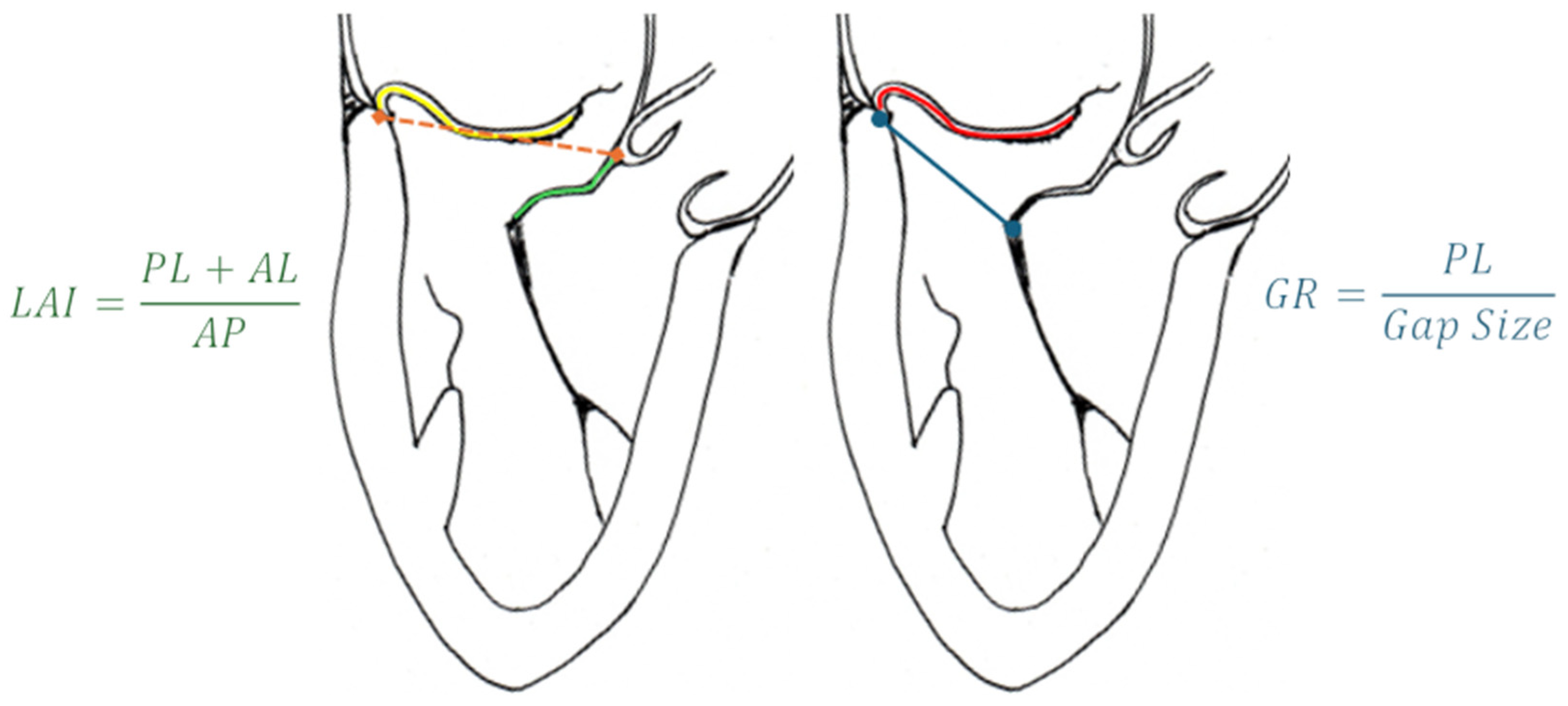
- Colli A, Besola L, Montagner M, Azzolina D, Soriani N, Manzan E, Bizzotto E, Zucchetta F, Bellu R, Pittarello D, Gerosa G. Prognostic impact of leaflet-to-annulus index in patients treated with transapical off-pump echo-guided mitral valve repair with NeoChord implantation. Int J Cardiol. 2018 Apr 15;257:235-237. Epub 2018 Jan 31. [CrossRef] [PubMed]
- Feuchtner GM, Alkadhi H, Karlo C, Sarwar A, Meier A, Dichtl W, Leschka S, Blankstein R, Gruenenfelder J, Stolzmann P, Cury RC. Cardiac CT angiography for the diagnosis of mitral valve prolapse: comparison with echocardiography1. Radiology. 2010 Feb;254(2):374-83. [CrossRef] [PubMed]
- Palmisano A, Nicoletti V, Colantoni C, Monti CB, Pannone L, Vignale D, Darvizeh F, Agricola E, Schaffino S, De Cobelli F, Esposito A. Dynamic changes of mitral valve annulus geometry at preprocedural CT: relationship with functional classes of regurgitation. Eur Radiol Exp. 2021 Aug 13;5(1):34. [CrossRef] [PubMed]
- Suh YJ, Lee S, Chang BC, Shim CY, Hong GR, Choi BW, Kim YJ. Utility of Cardiac CT for Preoperative Evaluation of Mitral Regurgitation: Morphological Evaluation of Mitral Valve and Prediction of Valve Replacement. Korean J Radiol. 2019 Mar;20(3):352-363. [CrossRef] [PubMed]
- Xu B, Kocyigit D, Wang TKM, Tan CD, Rodriguez ER, Pettersson GB, Unai S, Griffin BP. Mitral annular calcification and valvular dysfunction: multimodality imaging evaluation, grading, and management. Eur Heart J Cardiovasc Imaging. 2022 Feb 22;23(3):e111-e122. [CrossRef] [PubMed]
- Koo HJ, Kang JW, Oh SY, Kim DH, Song JM, Kang DH, Song JK, Kim JB, Jung SH, Choo SJ, Chung CH, Lee JW, Yang DH. Cardiac computed tomography for the localization of mitral valve prolapse: scallop-by-scallop comparisons with echocardiography and intraoperative findings. Eur Heart J Cardiovasc Imaging. 2019 May 1;20(5):550-557. [CrossRef] [PubMed]
- Maggiore P, Anastasius M, Huang AL, Blanke P, Leipsic J. Transcatheter Mitral Valve Repair and Replacement: Current Evidence for Intervention and the Role of CT in Preprocedural Planning-A Review for Radiologists and Cardiologists Alike. Radiol Cardiothorac Imaging. 2020 Feb 13;2(1):e190106. [CrossRef] [PubMed]
- Faggioni L, Gabelloni M, Accogli S, Angelillis M, Costa G, Spontoni P, Petronio AS, Caramella D. Preprocedural planning of transcatheter mitral valve interventions by multidetector CT: What the radiologist needs to know. Eur J Radiol Open. 2018 Aug 31;5:131-140. [CrossRef] [PubMed]
- Chiarito M, Sanz-Sanchez J, Pighi M, Cannata F, Rubbio AP, Munafò A, Cao D, Roccasalva F, Pini D, Pagnotta PA, Ettori F, Petronio AS, Tamburino C, Reimers B, Colombo A, Di Mario C, Grasso C, Mehran R, Godino C, Stefanini GG. Edge-to-edge percutaneous mitral repair for functional ischaemic and non-ischaemic mitral regurgitation: a systematic review and meta-analysis. ESC Heart Fail. 2022 Oct;9(5):3177-3187. Epub 2022 Jun 29. [CrossRef] [PubMed]
- Ranganath P, Moore A, Guerrero M, Collins J, Foley T, Williamson E, Rajiah P. CT for Pre- and Postprocedural Evaluation of Transcatheter Mitral Valve Replacement. Radiographics. 2020 Oct;40(6):1528-1553. [CrossRef] [PubMed]
- Blanke P, Dvir D, Naoum C, Cheung A, Ye J, Thériault-Lauzier P, Spaziano M, Boone RH, Wood DA, Piazza N, Webb JG, Leipsic J. Prediction of fluoroscopic angulation and coronary sinus location by CT in the context of transcatheter mitral valve implantation. J Cardiovasc Comput Tomogr. 2015 May-Jun;9(3):183-92. Epub 2015 Mar 3. [CrossRef] [PubMed]
- Thériault-Lauzier P, Andalib A, Martucci G, Mylotte D, Cecere R, Lange R, Tchétché D, Modine T, van Mieghem N, Windecker S, Buithieu J, Piazza N. Fluoroscopic anatomy of left-sided heart structures for transcatheter interventions: insight from multislice computed tomography. JACC Cardiovasc Interv. 2014 Sep;7(9):947-57. Epub 2014 Aug 13. [CrossRef] [PubMed]
- Ingallina G, Rampa L, Dicandia M, Boccellino A, Melillo F, Stella S, Ancona F, Biondi F, Fiore G, Slavich M, Denti P, Maisano F, Montorfano M, Agricola E. Anesthesia-Induced Intraprocedural Downgrading of Mitral Regurgitation During Transcatheter Edge-to-Edge Repair. Am J Cardiol. 2023 Mar 1;190:25-31. Epub 2022 Dec 20. [CrossRef] [PubMed]
- Ikenaga H, Yoshida J, Hayashi A, Nagaura T, Yamaguchi S, Rader F, Siegel RJ, Kar S, Shiota T. Usefulness of Intraprocedural Pulmonary Venous Flow for Predicting Recurrent Mitral Regurgitation and Clinical Outcomes After Percutaneous Mitral Valve Repair With the MitraClip. JACC Cardiovasc Interv. 2019 Jan 28;12(2):140-150. [CrossRef] [PubMed]
- Shuyi Feng, Pengxu Kong, Shouzheng Wang, Fujian Duan, Fengwen Zhang, Yongquan Xie, Zefu Li, Wenchao Li, Xiangbin Pan. Feasibility of a Percutaneous and Non-Fluoroscopic Procedure for Transcatheter Mitral Valve Edge-to-Edge Repair. Rev. Cardiovasc. Med. 2023, 24(12), 346. [CrossRef]
- Pascual I, Pozzoli A, Taramasso M, Maisano F, Ho EC. Fusion imaging for transcatheter mitral and tricuspid interventions. Ann Transl Med. 2020 Aug;8(15):965. [CrossRef] [PubMed]
- Zoghbi WA, Jone PN, Chamsi-Pasha MA, Chen T, Collins KA, Desai MY, Grayburn P, Groves DW, Hahn RT, Little SH, Kruse E, Sanborn D, Shah SB, Sugeng L, Swaminathan M, Thaden J, Thavendiranathan P, Tsang W, Weir-McCall JR, Gill E. Guidelines for the Evaluation of Prosthetic Valve Function With Cardiovascular Imaging: A Report From the American Society of Echocardiography Developed in Collaboration With the Society for Cardiovascular Magnetic Resonance and the Society of Cardiovascular Computed Tomography. J Am Soc Echocardiogr. 2024 Jan;37(1):2-63. [CrossRef] [PubMed]
- Gheorghe L, Ielasi A, Rensing BJWM, Eefting FD, Timmers L, Latib A, Swaans MJ. Complications Following Percutaneous Mitral Valve Repair. Front Cardiovasc Med. 2019 Oct 18;6:146. [CrossRef] [PubMed]
- Perl L, Kheifets M, Guido A, Agricola E, Denti P, Wild MG, Praz F, Rubbio AP, Bedogni F, De Marco F, Beeri R, Shuvy M, Melillo F, Montorfano M, Freixa X, de la Fuente Mancera JC, Giordano A, Finizio F, Van Mieghem NM, Ooms JFW, Fam N, O’Connor C, Toggweiler S, Levi A, Shapira Y, Schwartzenberg S, Pidello S, D’Ascenzo F, Angelini F, Haberman D, Crimi G, Porto I, Cozzi O, Giannini F, Tarantini G, Maisano F, Kornowski R; MITRA-EF study *. Acute Reduction in Left Ventricular Function Following Transcatheter Mitral Edge-to-Edge Repair. J Am Heart Assoc. 2023 Jul 4;12(13):e029735. Epub 2023 Jun 22. [CrossRef] [PubMed]
- Utsunomiya H, Itabashi Y, Kobayashi S, Rader F, Hussaini A, Makar M, Trento A, Siegel RJ, Kar S, Shiota T. Effect of Percutaneous Edge-to-Edge Repair on Mitral Valve Area and Its Association With Pulmonary Hypertension and Outcomes. Am J Cardiol. 2017 Aug 15;120(4):662-669. Epub 2017 May 30. [CrossRef] [PubMed]
- Paukovitsch M, Schneider LM, Reichart C, Nita N, Rottbauer W, Keßler M, Markovic S. Prevalence of iatrogenic atrial septal defects (iASD) after mitral valve (MV) transcatheter edge-to-edge repair (TEER) in the long-term follow-up. Open Heart. 2021 Oct;8(2):e001732. [CrossRef] [PubMed]
- Beri N, Singh GD, Smith TW, Fan D, Boyd WD, Rogers JH. Iatrogenic atrial septal defect closure after transseptal mitral valve interventions: Indications and outcomes. Catheter Cardiovasc Interv. 2019 Nov 15;94(6):829-836. Epub 2019 Apr 19. [CrossRef] [PubMed]
- Kargoli F, Pagnesi M, Rahgozar K, Goldberg Y, Ho E, Chau M, Colombo A, Latib A. Current Devices and Complications Related to Transcatheter Mitral Valve Replacement: The Bumpy Road to the Top. Front Cardiovasc Med. 2021 Jun 11;8:639058. [CrossRef] [PubMed]
- Heiser L, Gohmann RF, Noack T, Renatus K, Lurz P, Thiele H, Seitz P, Gutberlet M. CT Planning prior to Transcatheter Mitral Valve Replacement (TMVR). Rofo. 2022 Apr;194(4):e1. English. Epub 2022 Apr 20. Erratum for: Rofo. 2022 Apr;194(4):373-383. [CrossRef] [PubMed]
- Bapat VV, Khaliel F, Ihleberg L. Delayed migration of Sapien valve following a transcatheter mitral valve-in-valve implantation. Catheter Cardiovasc Interv. 2014 Jan 1;83(1):E150-4. Epub 2013 Aug 12. [CrossRef] [PubMed]
- Crowhurst JA, Scalia GM, Whitby M, Murdoch D, Robinson BJ, Turner A, Johnston L, Margale S, Natani S, Clarke A, Burstow DJ, Raffel OC, Walters DL. Radiation Exposure of Operators Performing Transesophageal Echocardiography During Percutaneous Structural Cardiac Interventions. J Am Coll Cardiol. 2018 Mar 20;71(11):1246-1254. [CrossRef] [PubMed]
- Corrigan FE 3rd, Hall MJ, Iturbe JM, Condado JF, Kamioka N, Howell S, Thourani VH, Clements SD, Babaliaros VC, Lerakis S. Radioprotective strategies for interventional echocardiographers during structural heart interventions. Catheter Cardiovasc Interv. 2019 Feb 1;93(2):356-361. Epub 2018 Sep 9. [CrossRef] [PubMed]
- Paulus MG, Meindl C, Hamerle M, Schach C, Maier LS, Debl K, Birner C, Unsöld B. Reduction of radiation exposure during transcatheter edge-to-edge mitral valve repair. Catheter Cardiovasc Interv. 2022 Mar;99(4):1259-1267. Epub 2022 Jan 27. [CrossRef] [PubMed]
- Melillo F, Fisicaro A, Stella S, Ancona F, Capogrosso C, Ingallina G, Maccagni D, Romano V, Ruggeri S, Godino C, Latib A, Montorfano M, Colombo A, Agricola E. Systematic Fluoroscopic-Echocardiographic Fusion Imaging Protocol for Transcatheter Edge-to-Edge Mitral Valve Repair Intraprocedural Monitoring. J Am Soc Echocardiogr. 2021 Jun;34(6):604-613. Epub 2021 Jan 13. [CrossRef] [PubMed]
- Faza NN, Harb SC, Wang DD, van den Dorpel MMP, Van Mieghem N, Little SH. Physical and Computational Modeling for Transcatheter Structural Heart Interventions. JACC Cardiovasc Imaging. 2024 Apr;17(4):428-440. [CrossRef] [PubMed]
- Faza NN, Özden Tok Ö, Hahn RT. Imaging in Structural Heart Disease: The Evolution of a New Subspecialty. JACC Case Rep. 2019 Oct 2;1(3):440-445. [CrossRef] [PubMed]
- Złahoda-Huzior A, Januska J, Hecko J, Khokhar A, Dudek D. Virtual reality-assisted heart team consultation for complex structural heart intervention. Eur Heart J Case Rep. 2022 Dec 13;7(1):ytac477. [CrossRef] [PubMed]
- Veulemans V, Hellhammer K, Polzin A, Bönner F, Zeus T, Kelm M. Current and future aspects of multimodal and fusion imaging in structural and coronary heart disease. Clin Res Cardiol. 2018 Aug;107(Suppl 2):49-54. Epub 2018 Jun 12. [CrossRef] [PubMed]
- Dabiri Y, Yao J, Mahadevan VS, Gruber D, Arnaout R, Gentzsch W, Guccione JM, Kassab GS. Mitral Valve Atlas for Artificial Intelligence Predictions of MitraClip Intervention Outcomes. Front Cardiovasc Med. 2021 Dec 10;8:759675. [CrossRef] [PubMed]
- Dabiri Y, Mahadevan VS, Guccione JM, Kassab GS. Machine learning used for simulation of MitraClip intervention: A proof-of-concept study. Front Genet. 2023 Mar 9;14:1142446. [CrossRef] [PubMed]
- Little SH, Rigolin VH, Garcia-Sayan E, Hahn RT, Hung J, Mackensen GB, Mankad S, Quader N, Saric M. Recommendations for Special Competency in Echocardiographic Guidance of Structural Heart Disease Interventions: From the American Society of Echocardiography. J Am Soc Echocardiogr. 2023 Apr;36(4):350-365. Epub 2023 Feb 24. [CrossRef] [PubMed]
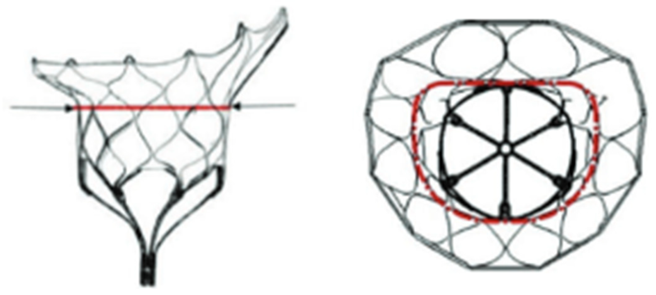


| Model | Number | AP (mm) | IC (mm) | Perimeter (mm) | EOA (cm2) |
|---|---|---|---|---|---|
| SP | 33S | 32.5 | 43.5 | 130 | 3.0 |
| 33M | 32.5 | 46.5 | 136 | ||
| 33L | 32.5 | 50.5 | 144 | ||
| 35M | 34.5 | 48.5 | 144 | ||
| 37S | 36.5 | 46.5 | 144 | ||
| 37L | 36.5 | 52.5 | 156 | ||
| 39M | 38.5 | 50.5 | 156 | ||
| 41S | 40.5 | 47.5 | 154 | ||
| LP | 29S | 29.0 | 42.5 | 119 | 2.2 |
| 29L | 29.0 | 47.5 | 129 | ||
| 33S | 32.5 | 43.5 | 130 | ||
| 35M | 34.5 | 48.5 | 144 | ||
| 37M | 36.5 | 49.5 | 150 |
Disclaimer/Publisher’s Note: The statements, opinions and data contained in all publications are solely those of the individual author(s) and contributor(s) and not of MDPI and/or the editor(s). MDPI and/or the editor(s) disclaim responsibility for any injury to people or property resulting from any ideas, methods, instructions or products referred to in the content. |
© 2024 by the authors. Licensee MDPI, Basel, Switzerland. This article is an open access article distributed under the terms and conditions of the Creative Commons Attribution (CC BY) license (https://creativecommons.org/licenses/by/4.0/).


