2.1. Laban's Effort Actions Theory to Refine and Communicate the Quality of Movement of the Golf Swing
Laban's Eight Effort Actions, also known as Laban Effort Drives, are a key part of Rudolf Laban's system for understanding and notating dance and movement, known as Laban Movement Analysis (LMA) [
15,
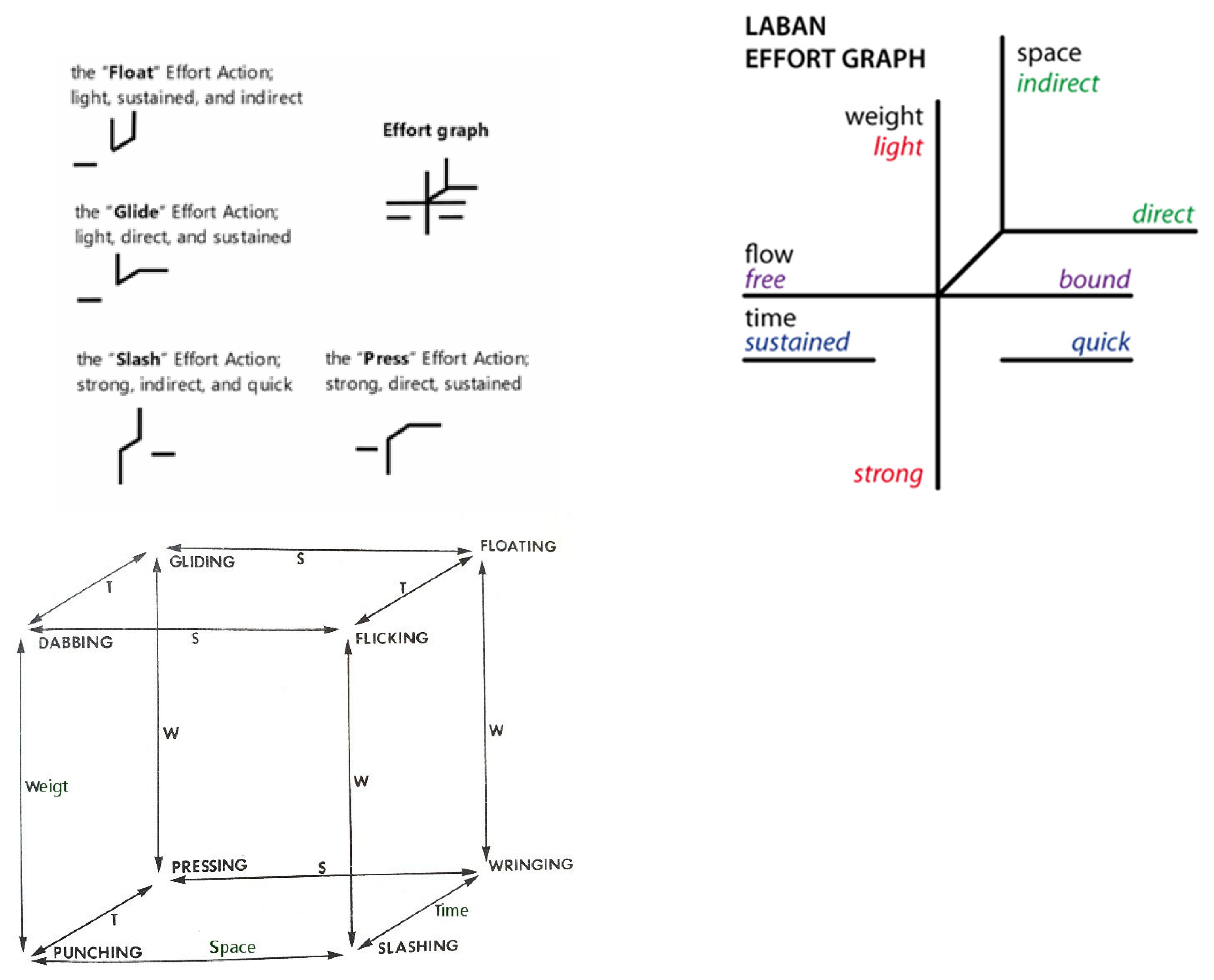
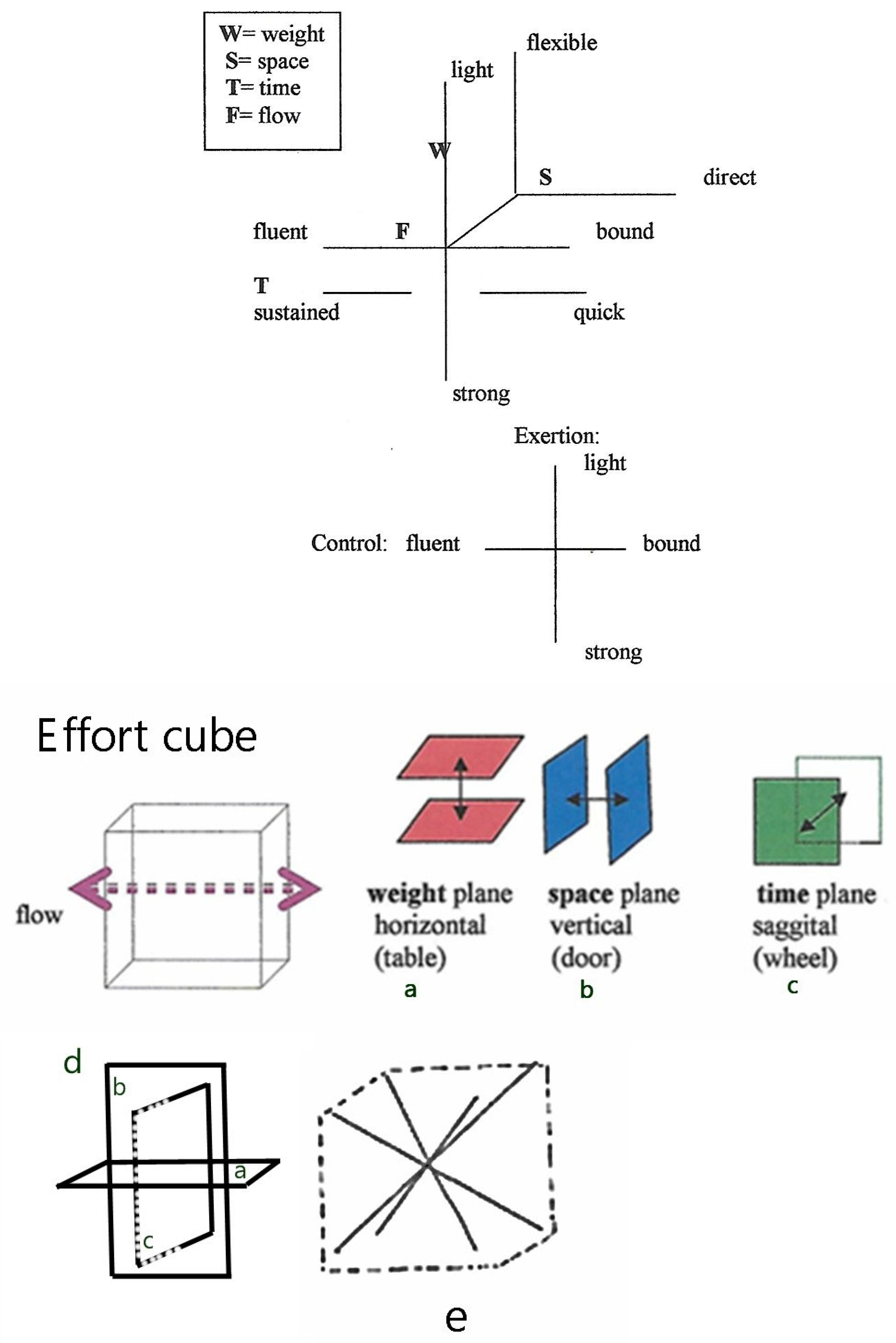
16]. These Effort Actions are used to describe the quality of movement and are organized according to Laban's Effort-Shape theory, which considers both the inner intention and the outer shape of the movement. The eight Effort Actions are categorized into four pairs of opposite qualities, with each pair representing one of the factors of motion: Weight, Time, Space, and Flow (
Figure 1(a)). The graph shows how these polarities interact to create various movement qualities, such as Gliding (Light, Sustained, Direct), Flicking (Light, Sudden, Indirect), Pressing (Strong, Sustained, Direct), and Wringing (Strong, Sustained, Indirect). Each combination represents a unique effort and intention in movement. (Adapted from Laban's original work on movement analysis.)
This Effort graph was created by Laban to delineate his organization of inner intent or motivation behind a movement. Light and Strong are the two polarities of Weight Effort, Sustained and Sudden are the two polarities of Time Effort, Direct and Indirect are the two polarities of Space Effort, Free and Bound are the two polarities of Flow Effort. In refining the understanding of the golf swing, this study applies Rudolf Laban’s Eight Effort Actions, part of the Laban Movement Analysis (LMA), which characterizes movement through dynamic qualities. Each of these actions corresponds to a combination of Effort elements—Weight, Time, Space, and Flow—depicting how movement can be experienced and executed with varying intensities and intentions [
16].
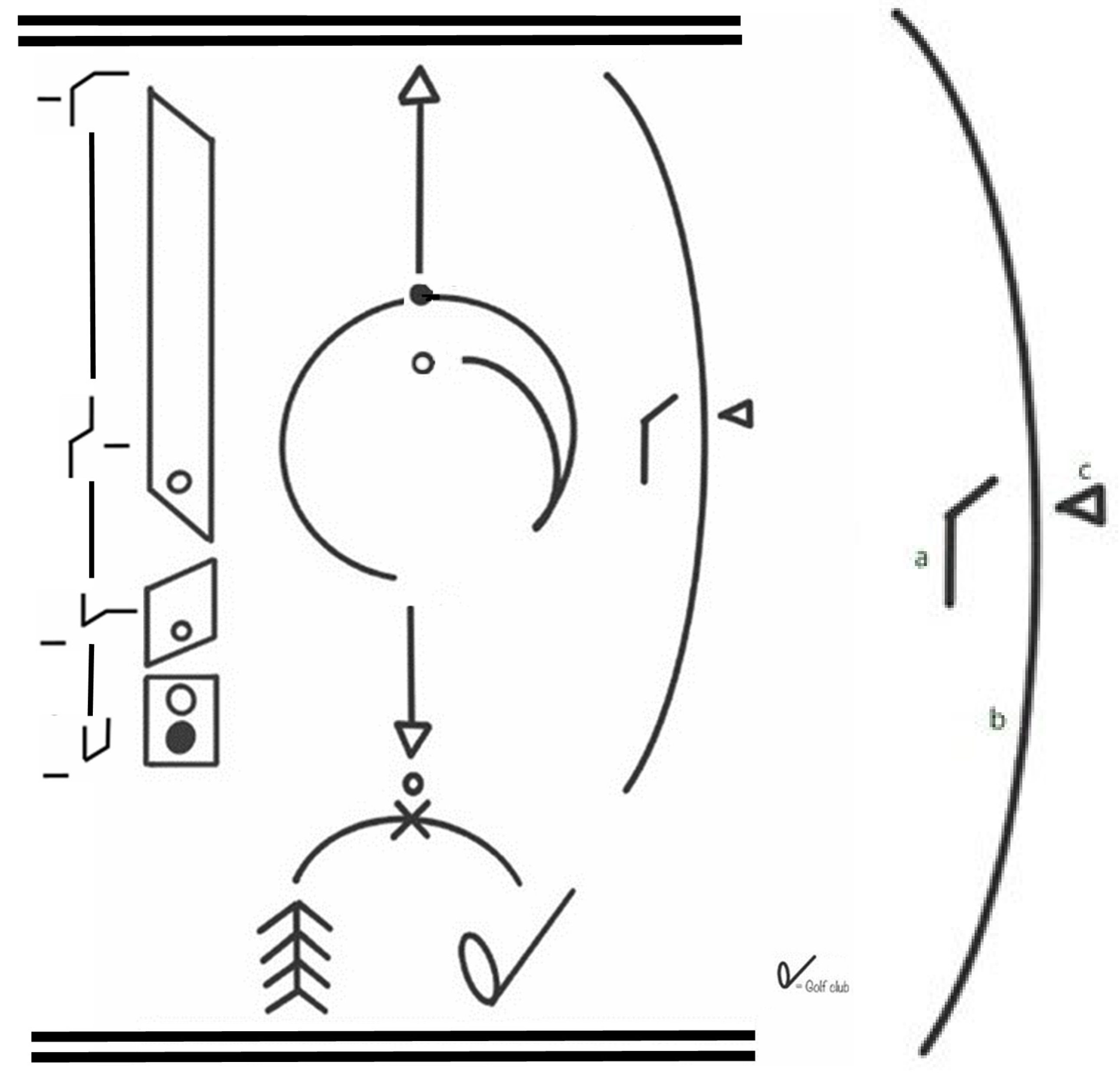
The golf swing, a sophisticated biomechanical action, encapsulates these Effort elements in its execution. The swing begins with a preparatory phase where the golfer aligns with the target, transitioning to the backswing, culminating in the powerful downswing. Each phase can be mapped to Laban's Effort Actions, offering a qualitative lens through which to analyze and refine movement (
Figure 1(b)).
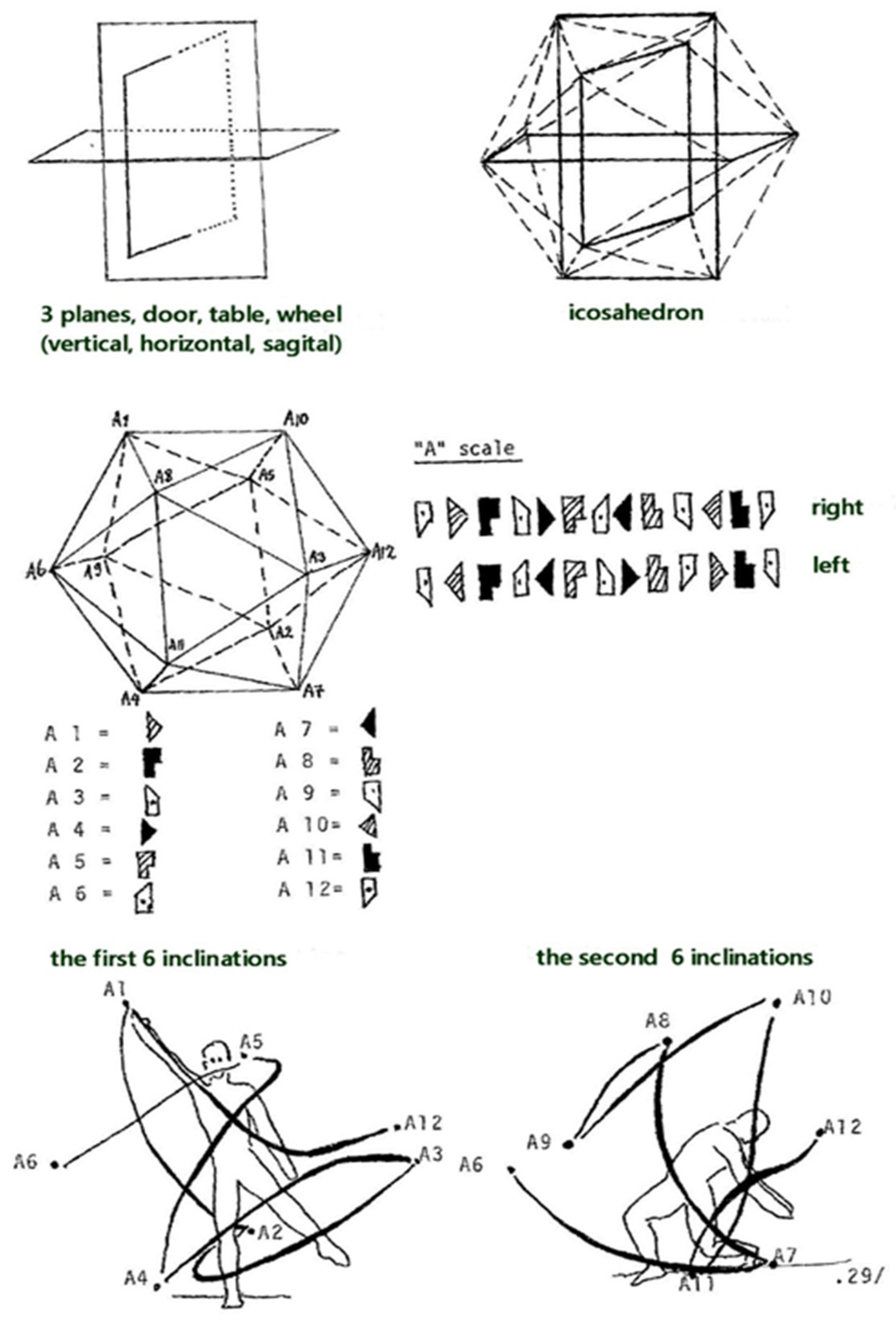
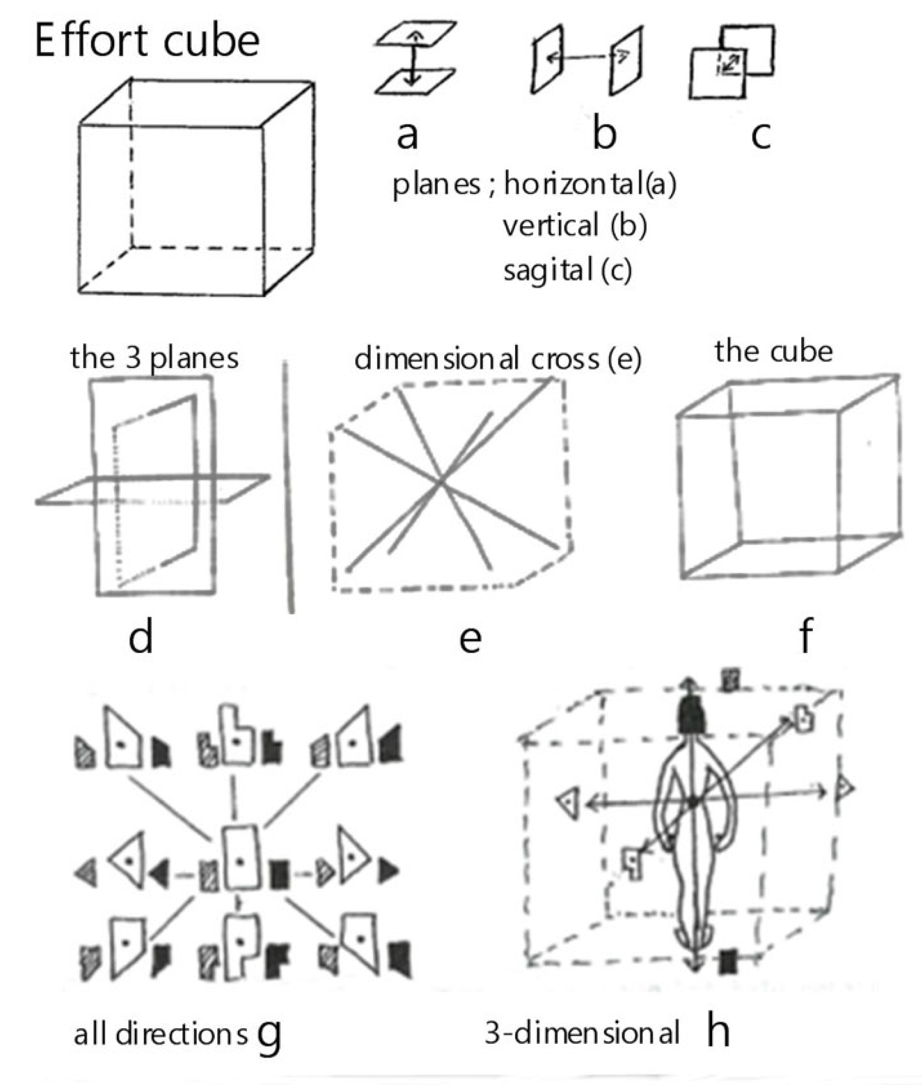
Figure 2. illustrates the application of Laban's Effort Cube and dimensional analysis to the phases of a golf swing. The Effort Cube, along with the three primary planes of motion (horizontal, vertical, and sagittal), provides a comprehensive framework for analyzing the qualitative aspects of movement. The figure includes various components that highlight the spatial and dynamic aspects of movement, aligning with Laban's Effort Actions. By expanding the explanation of
Figure 2 with these detailed
Table 1, we provide a comprehensive context that clarifies the data and enhances the reader's understanding of the application of Laban's Effort Actions to the golf swing. This integrated approach allows for a deeper analysis of both the qualitative and biomechanical aspects of the movement, ultimately improving performance and understanding.
The initial phase of the swing mirrors the 'Float' Effort Action—light, sustained, and indirect—where the golfer prepares, aligning body and mind with the intended direction and outcome. As the backswing progresses, the 'Glide' Effort Action—light, direct, and sustained—comes into play, signifying a smooth and controlled buildup of potential energy (
Figure 3). As the golfer transitions into the downswing, the Effort Actions shift towards more dynamic qualities. The 'Slash' Effort Action—strong, indirect, and quick—aptly describes the initiation of the downswing. Here, the stored potential energy is released into kinetic energy, demonstrating the efficient and powerful execution of the swing. Throughout the swing, minimizing unnecessary muscular tension is vital. A 'Free Flow' Effort quality ensures that movements are executed with minimal restraint, allowing for better coordination and fluidity. This quality is particularly critical during the downswing, where excessive tension can lead to a disrupted kinetic chain and inefficient energy transfer.
Effort quality in the context of the swing also directly impacts efficiency and timing. For instance, a 'Free Flow' in the Effort Action 'Press'—strong, direct, and sustained—can be seen in the even application of force through the impact with the ball, maximizing transfer of energy without unnecessary resistance. The implementation of LBMS in this context serves as an innovative method to convey the complex biomechanical and qualitative nuances of the golf swing. The inclusion of these Effort Actions within training regimens can enhance a golfer’s understanding of the physical and psychological elements at play, potentially leading to improved performance and a deeper appreciation for the subtleties of the sport.
As such, in this study, we seek to further explore these qualitative descriptors provided by Laban’s Effort Actions theory and apply them methodologically to analyze the intricate movements of the golf swing. Through this analysis, we aim to provide actionable insights that can be used to refine golf techniques and inform teaching and coaching practices.
This study employs screw theory [
17,
18] as a foundational mathematical framework to describe the spatial vector quantities relevant to the golf swing. Screw theory facilitates the representation of the six degrees of freedom of a rigid body (three translational and three rotational) in a unified manner. By defining the instantaneous screw axis (ISA) of the golf club, we capture both the rotational and translational dynamics essential for analyzing the complex movements in golf.
We use Plücker coordinates [
19] to represent these ISAs, allowing us to model the line of action and the moment around which the club rotates and translates during the swing. This approach provides a comprehensive understanding of the mechanical interactions between the golfer and the club, crucial for evaluating performance and technique.
The spatial inertia tensor [
20], a key concept from dynamics, is utilized to map the spatial acceleration space to the force space. Analogous to the error covariance tensor in estimation theory, this tensor encapsulates the inertia and mass properties of the golf club relative to the wrist joint, which is critical for understanding how golfers perceive and control the club during a swing. By decomposing the spatial inertia tensor into its geometric and constitutive components, we address complex eigenvalue problems that describe how different elements of the club's inertia influence the swing dynamics. This decomposition allows us to explore the interaction between the golfer's biomechanical inputs and the physical responses of the club. In this section of our paper, therefore, we present a method of free-vector decomposition for the spatial rigid-body inertia tensor. The linear map from the spatial acceleration space to the spatial force space was defined as the spatial inertia tensor. This spatial inertia (of a rigid body) has been successfully represented by means of a set of principal screws of inertia [
20]. Consider the situation in
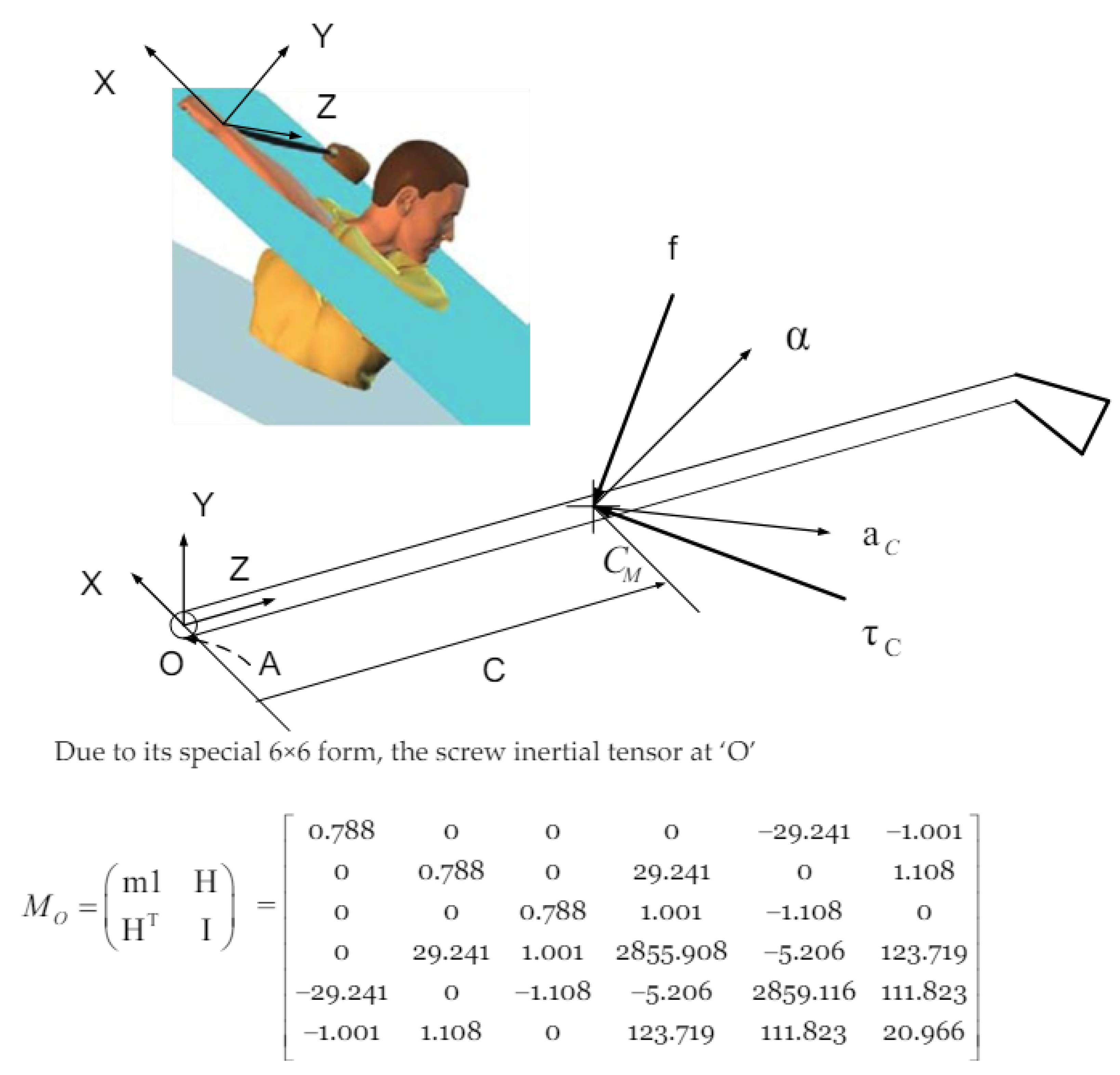
Figure 4: A club has a mass,
m; its center of mass,
CM, is given by the position vector,
C; and the inertia tensor about its center of mass is
J. The club is at rest, and experiences a force,
f, acting along a line passing through the center of mass, and a couple,
τC. The resulting acceleration is determined by an angular acceleration, α, along an axis passing through the center of mass (
CM), the linear acceleration,
aC, on
CM.
We present results that apply our modeling approach to the inertia tensor that was obtained by geometric scaling [
21], from a previously published dataset [
22]. Specifically, we did not directly measure the inertia tensor; rather, we used data obtained from a club made by the same manufacturer. Therefore, the inertia matrix included in
Figure 4 is a result of our own calculations based on these established methods and datasets. As such, the matrix is our original work, derived from the referenced data. The mass moment of inertia of the club was geometrically scaled by assuming that the moments of inertia of each segment are proportional to the mass times a linear dimension squared, as detailed by Zatsiorsky (1998). We then tuned segment parameters for a sample (including mass, location of center of mass, inertia) as described by MacKenzie & Sprigings (2009), to match the specific club used in our experiment.
The equation of motion is considered as a mapping from the twist-like screw acceleration to a wrench space [
23].
where

, and 1 is the 3×3
identity matrix.
Since all of the spatial quantities are referred to with respect to the center of mass, the linear and angular components of motion are decoupled – the linear acceleration being entirely due to the force, and the angular acceleration being a result of the couple. To transform Equation 1 into the origin of the joint axis (
Figure 4), we obtain
where H = C × M, I =J+C×MC×
T, and C× is
the anti-symmetric skew matrix corresponding to C.
Due to its special 6×6 form, the spatial inertial tensor
is expected to have special eigen structures.
The spatial inertia tensor
M0 represented at the origin is a symmetric, positive definite tensor and transforms to any point ‘A’ by the spatial Jacobian,
Φ, according to
where

and

.
The eigenvalue problem provides a unique decomposition of
M0 as
where
mf and
mγ are
representing the eigen values of mass and mass moment of inertia, respectively
(following the common notational tactics for the principal axes of inertia, we
use

for
mγ
and, to the corresponding principal moment of inertia,

for
γ).
One might wonder whether the decomposition based on the solution for the free-vector eigenvalue problem would be different at another point A. We apply the transformation rule (Equation 5) to the above decomposition (Equation 6):
which shows that
MA is decomposed by the same eigenscrews in the same manner, just represented at B. That is, no matter where the problem is posed, the same eigenscrews form the basis of the decomposition.
2.3. Instrumentation and Data Analysis
In this study, rather than collecting new empirical data, we utilized an existing dataset from previous research that detailed the golf swings of two female golfers with different skill levels [
23] (
Table 2). This dataset was chosen for its comprehensive capture of biomechanical movements using high-precision motion capture technology and ground reaction force measurements, making it highly suitable for our analysis.
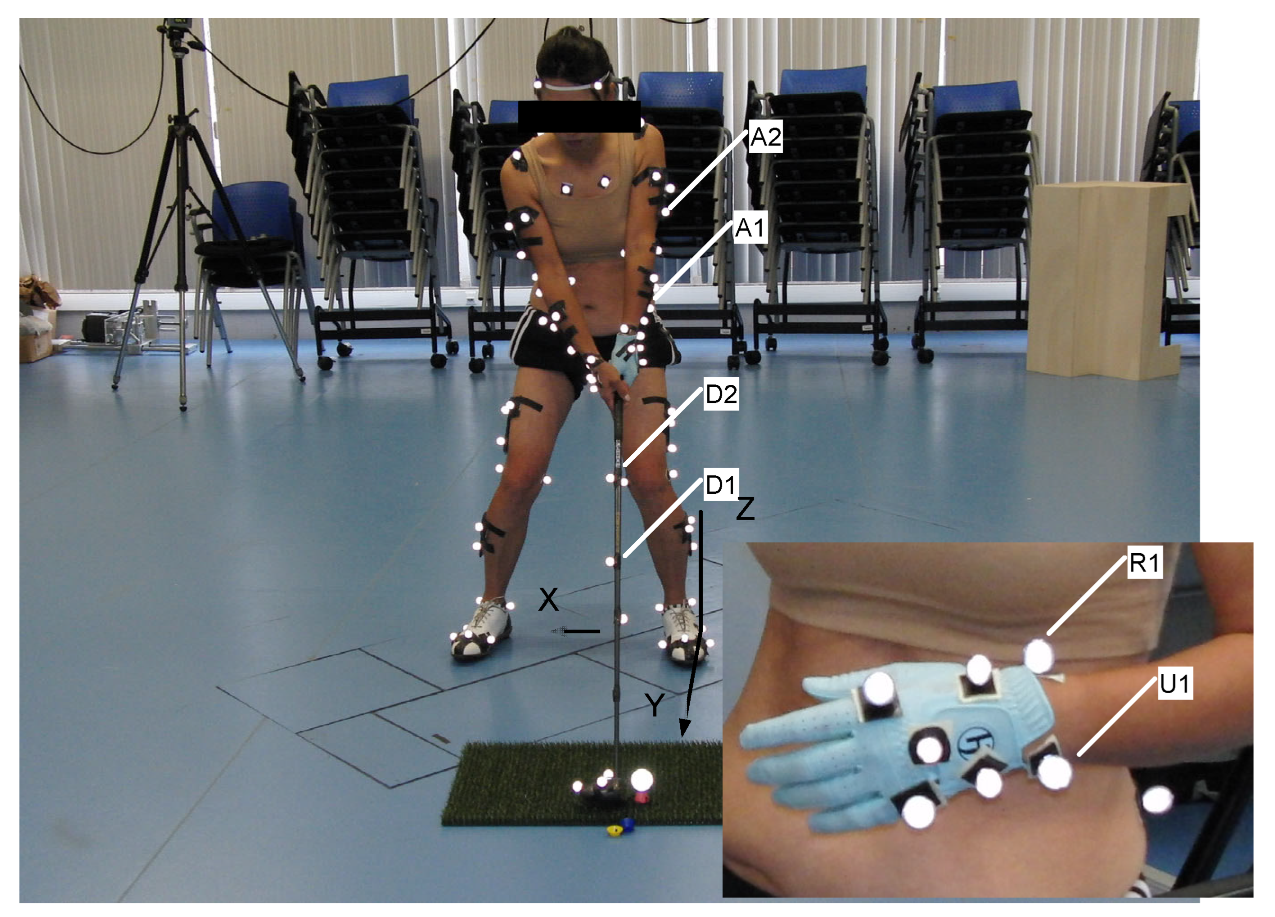
The original data were collected using a sophisticated array of twelve high-speed Qualisys cameras, which accurately recorded the three-dimensional positions of reflective markers attached to the golfers and their clubs. This setup was designed according to the standards of the International Society for the Advancement of Kinanthropometry, ensuring that the biomechanical analysis adhered to high measurement accuracy and reliability (
Figure 5). Ground reaction forces were measured using a Kistler force plate, providing essential data on the biomechanical forces exerted during the swings.
By reusing this existing dataset, we were able to directly apply our analytical models without the variability and resource constraints associated with new data collection. This approach also allowed us to focus on in-depth analysis using established data, ensuring that our study was both resource-efficient and grounded in reliable biomechanical metrics. The dataset included detailed annotations of each golfer's movements and the corresponding biomechanical outputs, which facilitated a nuanced analysis of the swing mechanics. In total, twenty-four reflective markers and four marker clusters were used for the reconstruction of eight body segments (i.e., the trunk, pelvis, thighs, shanks, and feet). Additionally, specific markers were placed on the club and wrist joint to define their respective reference frames. Marker coordinates for the period between the beginning of the downswing of a golf swing and up to the instant before impact were then acquired.
Motion capture was undertaken using an optoelectronic system of twelve Qualisys cameras (type: Oqus-300, Qualisys AB, Sweden) operating at 300Hz. The collected data were processed using Qualisys Track Manager (QTM) software to ensure accurate tracking and reconstruction of the marker trajectories. For the club, markers were placed at specific points along the shaft and clubhead to capture its motion accurately. The wrist joint was defined using markers placed on anatomical landmarks around the wrist to establish a local reference frame.
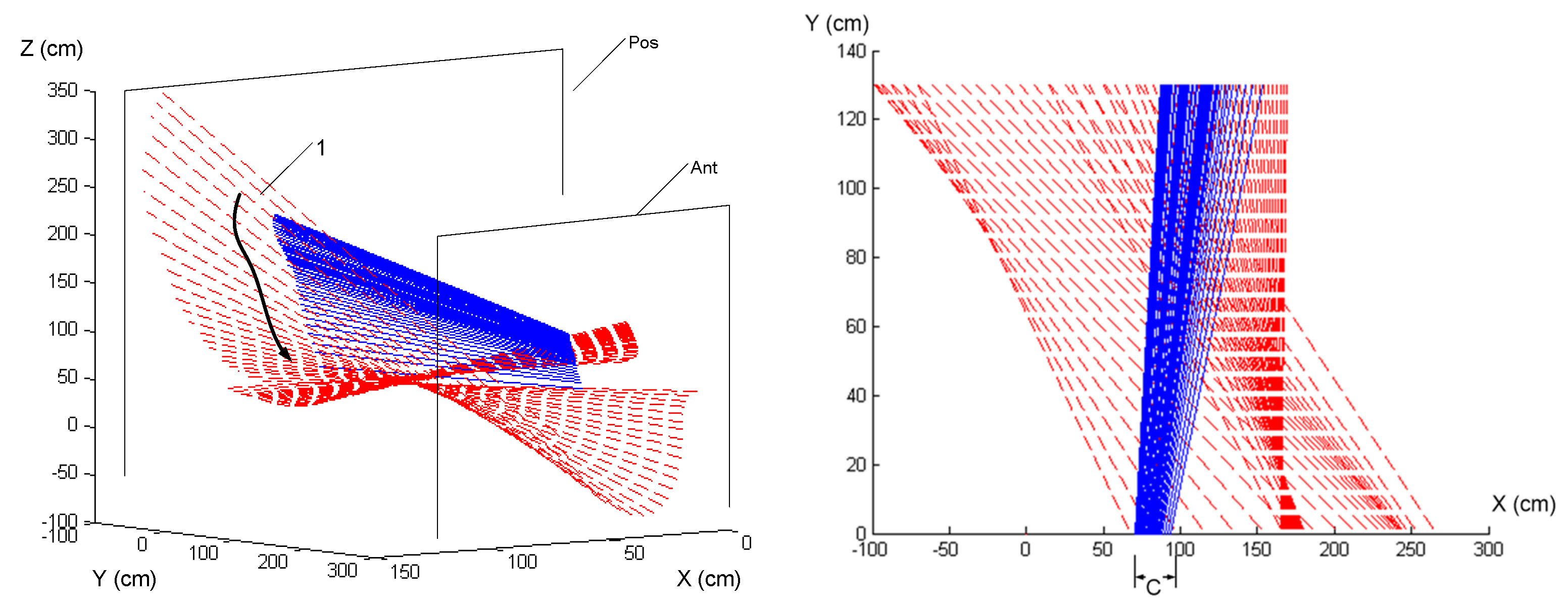
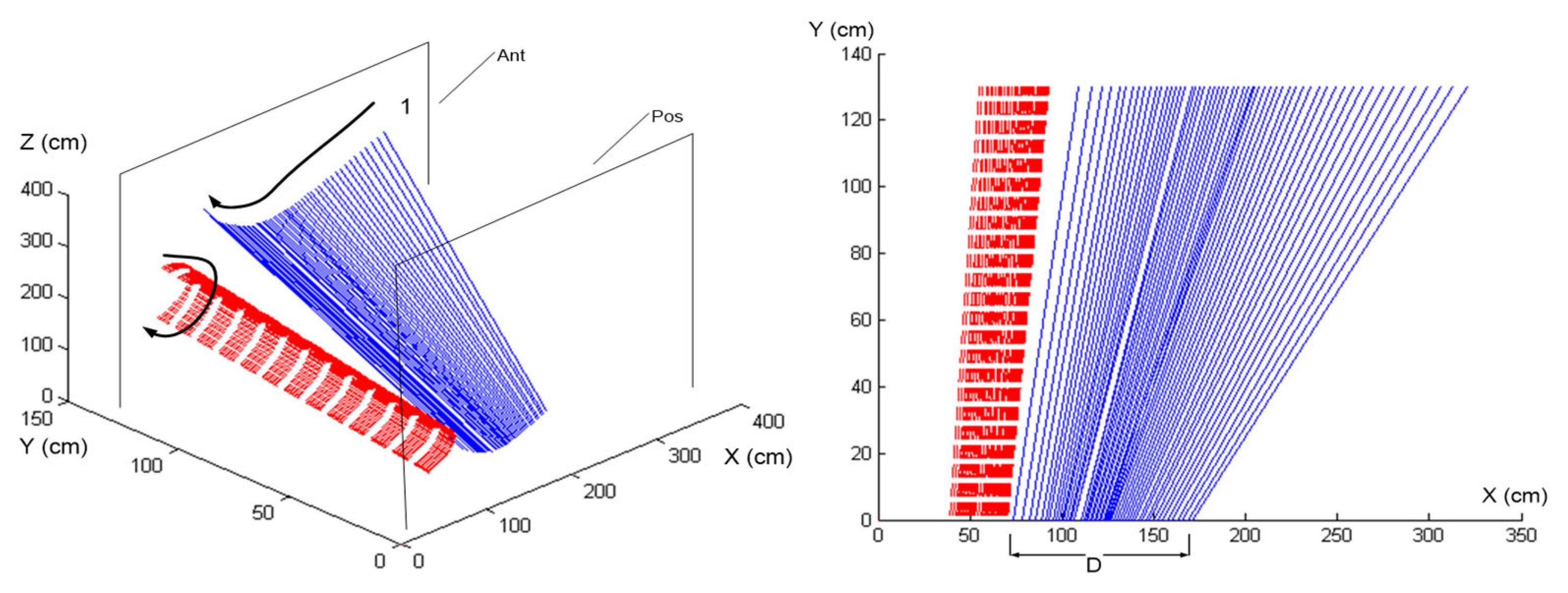
Using the predefined anatomical coordinate system from the original study, which was based on key landmarks identified on the golfer and the club, we analyzed the motion data to extract the instantaneous screw axes (ISA) and their evolution during the downswing phase. This previously recorded data provided a robust basis for exploring how biomechanical properties such as the ISA correlate with golfer skill level and technique efficacy.
Reusing data from a well-designed previous study can enhance the efficiency of the research process and contribute to the sustainability of research practices by utilizing existing resources. This method helps to ensure that findings are based on previously validated data, which can support the reliability of the conclusions drawn from the analysis.

 , and 1 is the 3×3
identity matrix.


 and
and  .
.
 for mγ
and, to the corresponding principal moment of inertia,
  for
γ).


 ).
).
 ).
).