1. Introduction
It's hard to overstate the crucial role that lasers
play in modern life. From welding, cutting, and drilling in subtractive
manufacturing [
1] to 3D printing in additive
manufacturing [
2], particularly in metal
processing, lasers are indispensable. Besides, they accelerate charged
particles to high energy [
3], produce hard
radiation [
4] crucial for various scientific
and medical applications, and have recently demonstrated breakthroughs such as
achieving breakeven in Confinement Nuclear Fusion [
5]
and enabling Extreme Ultraviolet Lithography [
6].
These are just a few examples showcasing the immense capabilities of high-power
lasers.
Laser systems are broadly classified based on their
operating regimes into two main categories: Continuous Wave (CW) operation,
where the laser is continuously pumped and emits a steady beam of light, and
the pulsed regime, in which the laser produces single or multiple pulses at
various repetition rates.
In CW regime high power fiber lasers are created
from active optical fibers pumped by semiconductor laser diodes, a merger
between two of the most innovative and advanced laser technologies reached the
remarkable output power up to 100s kW [
7] and
feature a wide range of operating wavelengths and record wall-plug efficiency
up to 50% [
8]. Multi-kW carbon oxide (CO
2)
gas lasers present another example of greater reliability, higher output
consistency, which allowed them the widely spread in industry and medicine [
9].
Nevertheless, this paper will primarily focus on
ultrahigh power pulsed laser systems, exploring their various types and recent
technological advancements. High power laser systems possess the ability to
concentrate the energy into extremely small space-time volume. The laser beam
with recently reached 10 petawatts (10
15 Watt -PW) output pulse
power was focused on the few microns spot which allowed to achieve the highest
in the observable universe intensity approaches to 10
24 watts per
square centimeter (W/cm
2) [
10].
With a duration of approximately 20 femtoseconds (10
-15
seconds - fs), this pulse occupies a mere ~7 μm of space during its
propagation. Such a short pulse duration enables the attainment of tremendous
power and intensity with a modest energy input ranging from 300 to 500 Joules. To put this into perspective, consider that the total
power output of all the world's power plants is around 2 terawatts (10
12
watts - TW), while the sunlight reaching the Earth amounts to approximately 90
PW. Achieving an intensity of 10
24 W/cm
2 is feasible by
concentrating this power into a spot with a diameter of just 30 μm.
The light produced by cutting-edge technologies
boasts remarkable specifications, revolutionizing various fields of science and
industry. Take, for instance, the Extreme Light Infrastructure for Nuclear
Physics (ELI-NP) 20PW laser, crafted from sapphire crystals doped with titanium
ions (Ti:Sa). This system generates 600J of output energy with a pulse duration
of 30 fs across two converging channels [
10].
In a different league, the NIF Nd: Glass laser system, pivotal in achieving
thermonuclear fusion breakeven, wields a staggering 4MJ of energy at a
wavelength of 1.053 μm, converted in 1.8MJ of third harmonic at 0.35 μm through
192 channels. Its pulse duration spans a nanosecond, with an output power of
0.5PW [
11]. Furthermore, ASML employs a 1MW CO
2
gas laser within their Extreme Ultraviolet Lithography system, revolutionizing
microchip production [
12], showcasing just a
glimpse of the transformative capabilities of these cutting-edge light sources.
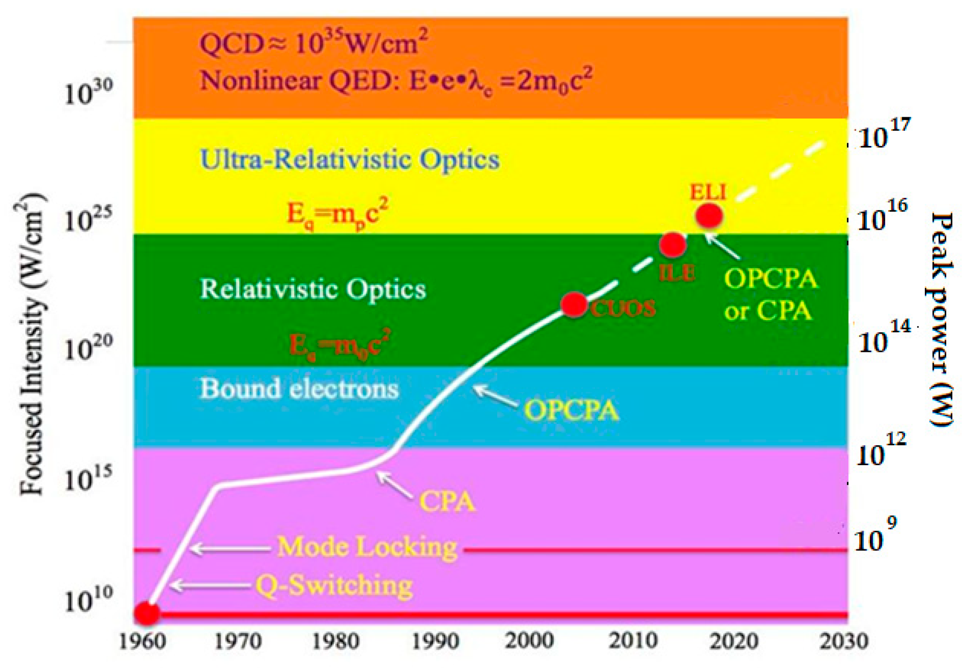
Figure 1
demonstrated the chart of historical development of the laser systems with high
pulse power (intensity).
Since Richard Maiman's groundbreaking invention of
the laser in 1960 [
13], the power of laser
technology has undergone rapid growth, fueled primarily by the discovery of two
pivotal operational regimes: Q-Switching and Mode Locking (a detailed
explanation follows) [
14,
15]. These
breakthroughs, illustrated on the accompanying chart, marked a turning point in
laser development. By implementing these regimes in laser oscillators,
scientists and engineers achieved a remarkable feat: the gradual reduction of
pulse durations from microseconds to nanoseconds, and later, to femtoseconds,
all without significant energy loss. The peak power is determined by dividing
the energy by the pulse duration, thus there are two primary pathways to
increase peak power. The first is extensive, involving increasing the energy
output of the laser by developing Master Oscillator+ Power Amplifiers (MOPA)
scheme. The second is intensive, focusing on reducing the pulse duration.
Intensive improvements, such as pulse duration reduction, are often favored due
to their cost-effectiveness. By enhancing the efficiency and precision of laser
systems, researchers can achieve higher peak powers without significantly
increasing energy consumption or production costs. This approach underscores
the importance of refining pulse duration technologies, which not only boosts
parameters but also promotes accessibility in laser applications across various
new fields.
Following the period of gradual intensity growth
post-1970, a significant technological breakthrough emerged in 1985: Chirped
Pulse Amplification (CPA) [
16,
17]. This
innovation provided a substantial boost to laser capabilities, propelling the
power growth trajectory forward, a trend that continues to evolve to this day
and beyond. The development of Chirped Pulse Amplification (CPA) involved the
collective efforts of numerous scientists over the years. While it's true that
two individuals were awarded the Nobel Prize in 2018 for their contributions to
CPA, namely Jerard Mourou and Dona Strickland, it's essential to recognize the
collaborative nature of scientific progress. Countless researchers worldwide
have dedicated their knowledge, expertise, and resources to advancing CPA
technology, each playing a vital role in its development and refinement. In
this paper, we will delve into a comprehensive explanation of the
aforementioned technologies, elucidating their principles, applications, and
contributions to the evolution of laser science and industry.
2. Ideas and Methods of Laser Power Increasing
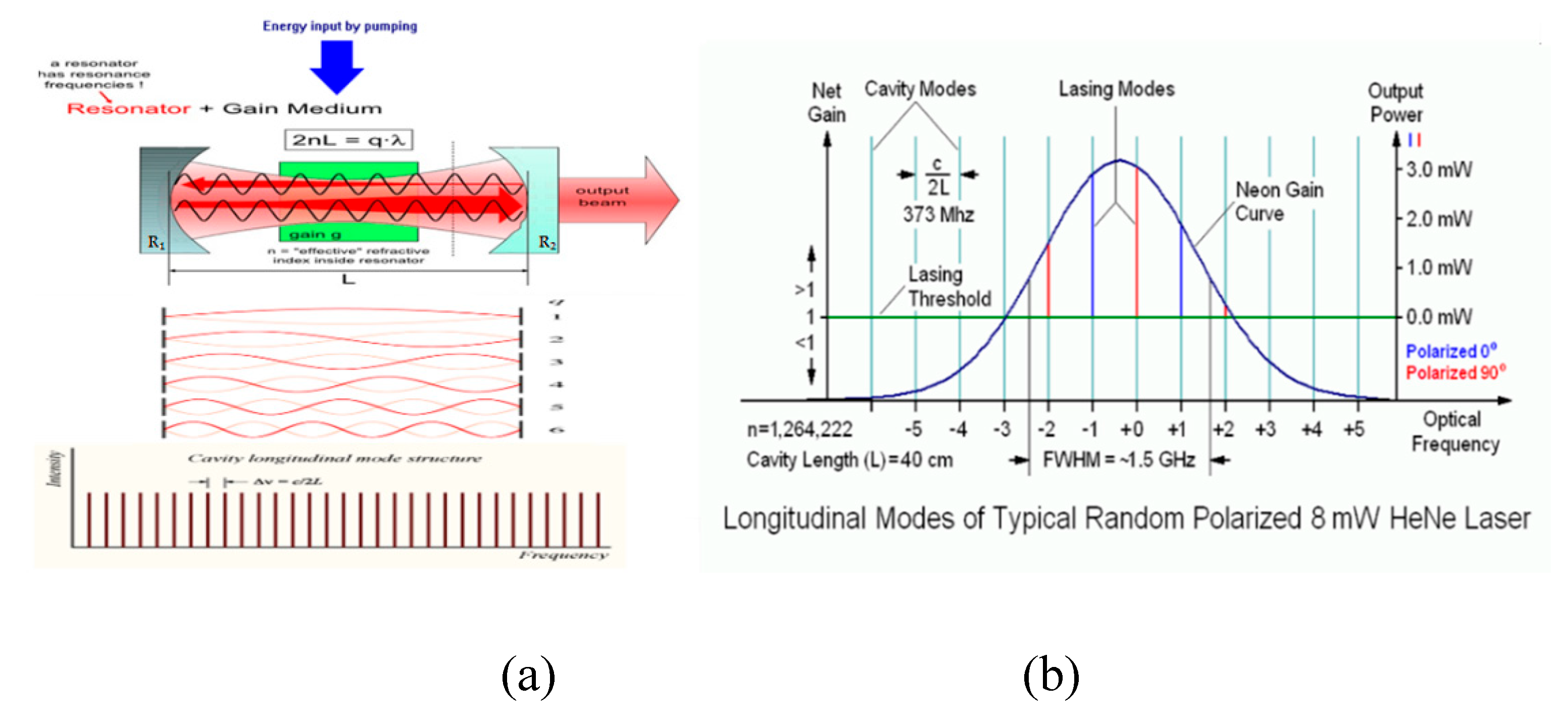
Let's begin with a brief overview of how a laser
oscillator operates. For a deeper understanding, readers can refer to [
18]. In essence, a laser oscillator comprises three
primary components: a resonator or cavity, typically consisting of two mirrors
(one of which is usually partially transparent, serving as the output coupler),
a Gain Medium (GM) that facilitates amplification of light within a specific
spectral range, and a pump system responsible for energizing the gain medium to
enable light amplification (refer to
Figure 2a
top for illustration).
Some of the spontaneous photons generated by GM and
reflected by mirrors of the cavity can produce standing waves or resonance
frequencies (longitude modes) which are able respectively long time exist in
resonator, for example, as standing waves on the guitar string. The condition
for that is the equivalence of number (q) of half-waves (λ/2) to resonator
length (L) multiplied by the index of refraction (n) of the media nL= qλ/2,
similar, the resonance frequencies can also be expressed as ν = qc/2L, where (c)
represents the speed of light.
Initially, the frequency amplitudes are uniform
within the empty cavity, depicted in
Figure 2a
at the bottom, with equidistant spacing calculated by the formula Δ
ν = c/2L, resulting in
an infinite array of frequencies. However, the resonator is not truly empty; it
contains a GM capable of amplifying the frequencies suitable with its
luminescence spectra. In reality, the laser medium (GM) exhibits specific
spectral bandwidths for light amplification, determined by its structure and
condition, as illustrated in
Figure 2b
(blue curve). Only a handful of frequencies align with this curve, as other
frequencies experience limited or no amplification. Additionally, losses occur
within the cavity due to imperfections in optical surfaces, finite apertures,
and output energy (R
1, R
2). Consequently, only a select
few modes persist within the resonator under steady-state conditions, matching
the amplification spectra and surpassing the losses. This condition means
lasing threshold and can be found by formula
R1R2
exp(-aL) exp(bL) =1, where
a is the coefficient of losses in the
cavity material,
b-the coefficient of amplification.
The lasing threshold is shown by the green line on
Figure 2b and only five mod amplitudes were
bigger than it, that means the laser is able generate only these mods. So, a
broader amplification spectrum of a gain medium allows generate the light with
the larger spectral bandwidths (more modes). The spectral bandwidth is directly
linked to the pulse duration produced by the laser, as dictated by the
uncertainty principle. In this context, it can be expressed as
Δν × Δτ = Const,
where
Δν
and
Δτ represent the spectral bandwidth and pulse duration typically
measured at the Full Width Half Maximum (FWHM) of their intensities.
Consequently, the product constant implies that a larger spectral bandwidth
results in a shorter pulse duration.
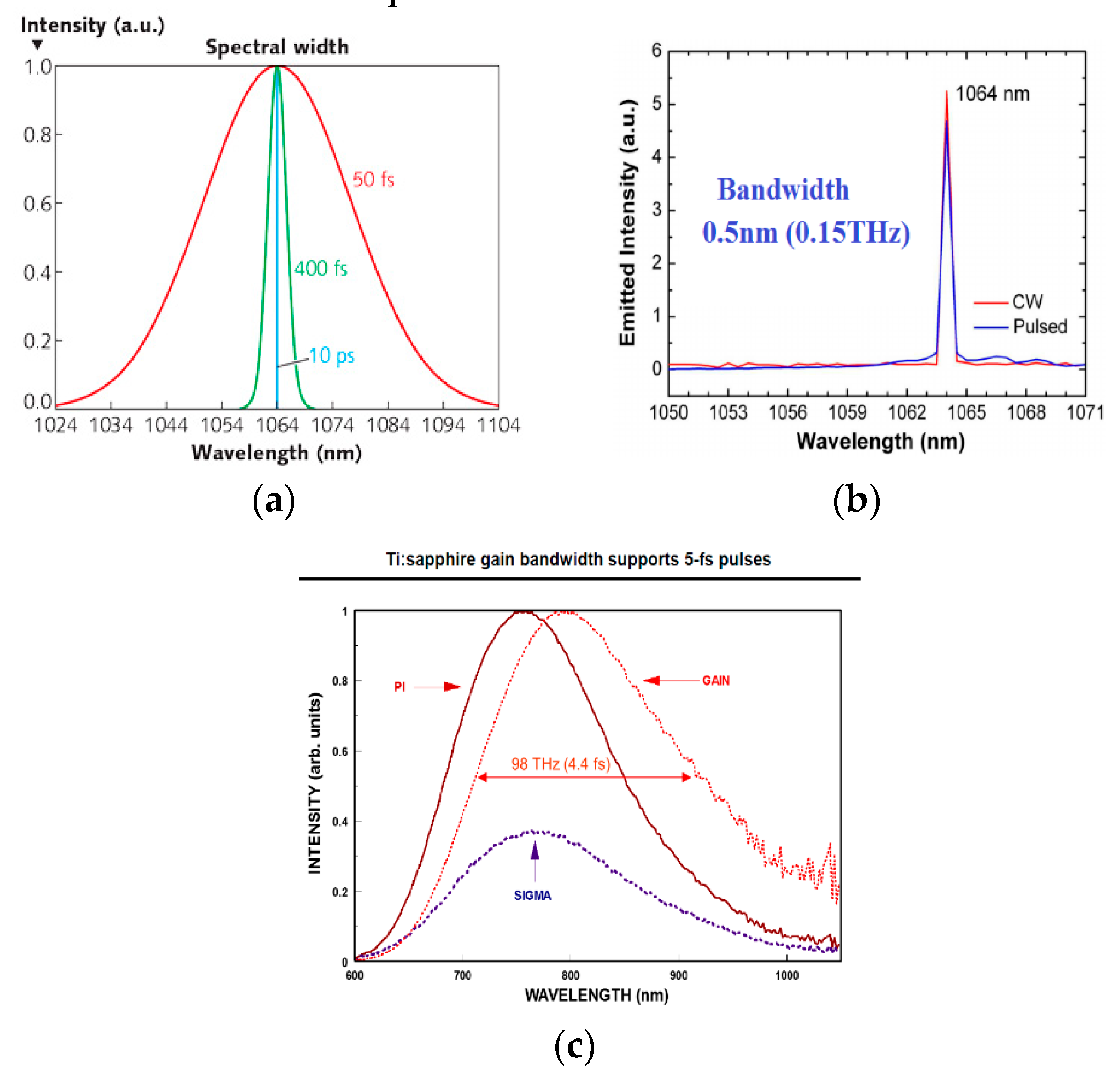
In
Figure 3a,
three spectral widths are depicted alongside pulse durations corresponding to
them. Notably, the pulse duration of 50 fs requires a much larger spectral
width compared to 10 ps (10
-12 seconds). Furthermore,
Figure 3b,c
illustrate the luminescence spectra of two laser crystals, Nd:YAG and Ti:Sa.
Oscillators utilizing these crystals typically generate 4 × 10
3 and
3 × 10
5 longitudinal modes respectively, resulting in spectral
bandwidths of 0.5 nm and 30 nm measured at FWHM.
Now, let's explore the practical methods of
receiving laser pulses. The simplest, albeit not the most effective, method
involves positioning an electromagnetic or mechanical interrupter within the CW
laser output beam. In this scenario, the continuous wave power will match the
pulsed power, despite losing energy. However, as evidenced by the chart in
Figure 1, following the invention of the laser
in 1960, its peak power experienced rapid growth over the subsequent decade, up
to 1970. This advancement can be attributed to the development of two key
technologies: "Q-switching" [
14] and
"Mode-locking" [
15].
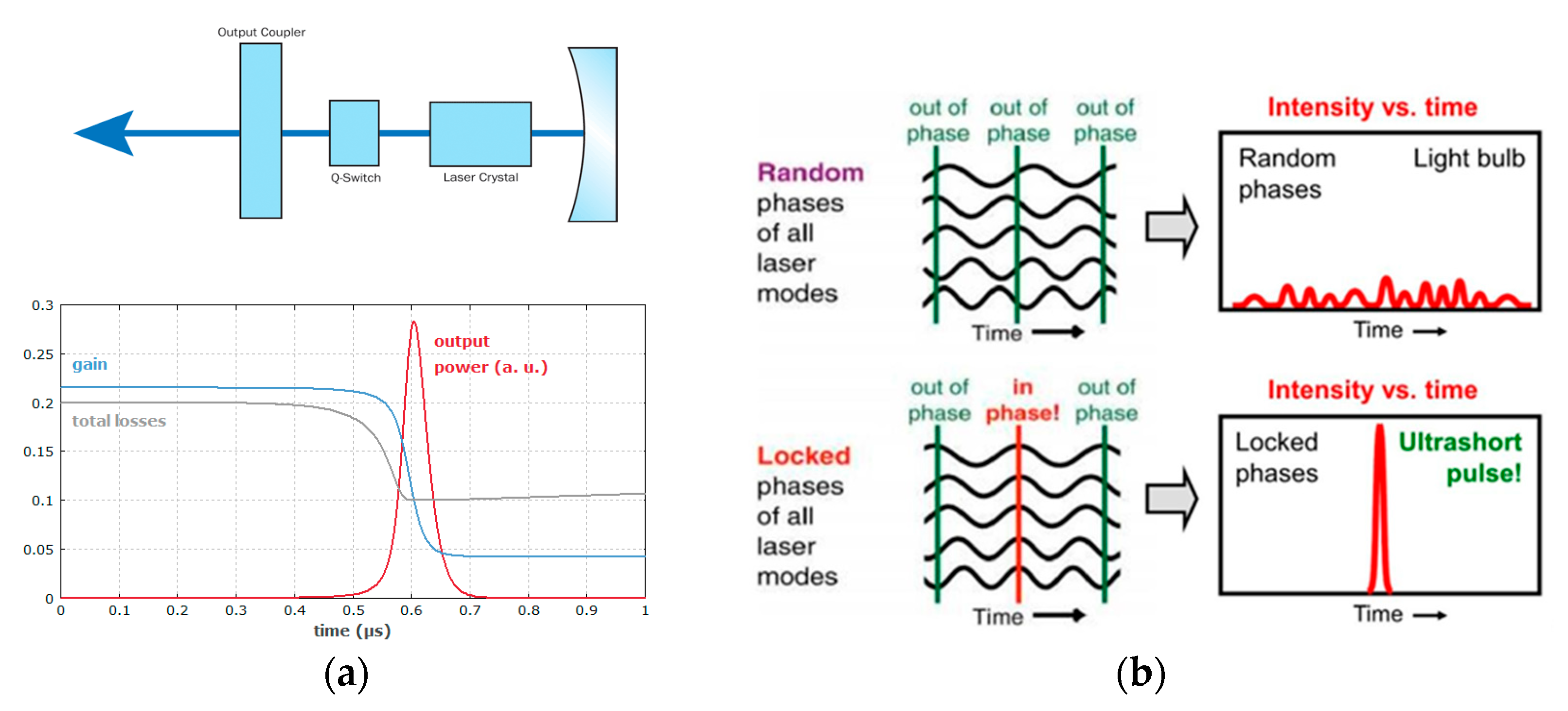
In the first method, unlike the previously
discussed approach, the switcher was positioned inside the laser resonator to
alter its Q-factor (quality factor), as depicted in
Figure 4a (top). The Q-factor in this
context can be defined as the ratio of stored energy to energy dissipated per
oscillation cycle. Essentially, a high Q- factor corresponds to low energy
losses in the cavity, and vice versa. When the Q-switch is closed (low Q-factor),
it prevents light propagation within the cavity during the pumping of the GM,
as illustrated in
Figure 4a (bottom).
Once sufficient energy is accumulated, the Q-switch is opened, allowing the
light photons spontaneously born in GM pass between the resonator mirrors and
undergo amplification in the gain medium by stimulating identical photons
emission, thereby increasing pulse energy.
The duration of the generated pulses is influenced
by several factors, including the resonator round-trip time, the initial gain,
and the resonator losses. A higher initial gain results in a quicker buildup of
pulses, leading to higher energy extraction and typically a faster decay of
power after reaching the pulse maximum. Generally, the duration of pulses is at
least on the order of the resonator round-trip time and often longer than 1
nanosecond (10-9 seconds - ns). Q-switch oscillators typically
produce pulses with a repetition rate in the range below megahertz, boasting
pulse powers up to megawatts (106 Watts - MW).
In the resonator, longitudinal modes exhibit
random phases, as depicted in
Figure 4b
(top). However, laser pulses can be significantly shortened by synchronizing
the cavity modes, as illustrated in
Figure 4b
(bottom). This synchronization, known as Mod-lock operation regime in laser
oscillators, ensures that the maximum amplitudes of all longitudinal modes
coincide at the same point and same time within the cavity. This constructive
summation results in a substantial increase in intensity at this point,
manifesting as a pulse with a duration of a few optical cycles (a few fs).
Furthermore, as more modes concentrate the energy in a smaller area, the pulse
duration becomes even shorter (see
Figure 3).
As the soliton traverses between cavity mirrors, its energy escalates to the
nano - microjoule level upon passing through the GM. A significant number of
modes or a broad spectral bandwidth necessitates a gain medium with a large
fluorescence spectrum, along with devices to compensate for dispersion in
optical elements, such as pairs of prisms [
19].
In practice, like Q-switching, achieving the Mode-locking regime can be
realized through external driving modulators within the laser resonator (active
mode locking) [
20] or by exploiting nonlinear
effects in the cavity elements, such as the Kerr effect or absorption
saturation (passive mode locking) [
21].
Advancements in these techniques, coupled with the integration of laser
oscillators with amplifiers, led to a remarkable increase in output laser pulse
power within a decade following the invention of lasers, achieving peak powers
of up to terawatts (TW) [
22]. However, further
increases in power necessitated significant enlargement of the aperture of
optical elements and gain media. This was due to the approaching of these
elements to their damage threshold and/or the onset of undesired nonlinear
effects, which can distort the laser beam and degrade pulse quality.
An effective method for increasing pulse power
involves reducing its duration rather than simply increasing energy, as
expressed by the equation
P=
E/
τ , where
P is power,
E is energy, and
τ is pulse duration.
However, it's essential to consider the damage threshold, which is proportional
to the square root of pulse duration. For instance, when pulse durations
approach tens of femtoseconds, the damage threshold can be as low as 100
millijoules per square centimeter (mJ/cm
2) of energy fluence.
Moreover, severe nonlinear effects such as self-focusing [
23] can occur even earlier, typically when energy
fluence approaches 1 mJ/cm
2, with critical power levels reaching
gigawatts (10
9 Watts - GW) in most cases. A direct method to
mitigate these undesirable phenomena is by increasing the aperture size, as it
was pointed out above. However, starting from the TW energy level, this
approach becomes exceedingly expensive and even impractical. For instance, to
achieve PW energy levels, a Ti:Sa crystal with a diameter of 3 meters would be
necessary for the final amplifier in the laser system.
A more creative approach was proposed back in 1985.
Initially, a short pulse with low energy is temporally stretched, resulting in
a longer duration suitable for further amplification. This allows for a
significantly reduced beam aperture. After accumulating a certain energy level
in a chain of amplifiers, the long pulse is then compressed back to its
original short pulse duration, yielding very high power. This groundbreaking
method is known as Chirped Pulse Amplification (CPA) technique [
16,
17]. CPA has proven immensely fruitful in the
development of ultra-high-power lasers, leading to a gradual increase in power
over the years (see
Figure 1). Recently,
it has even enabled the achievement of power levels up to 10 petawatts. The
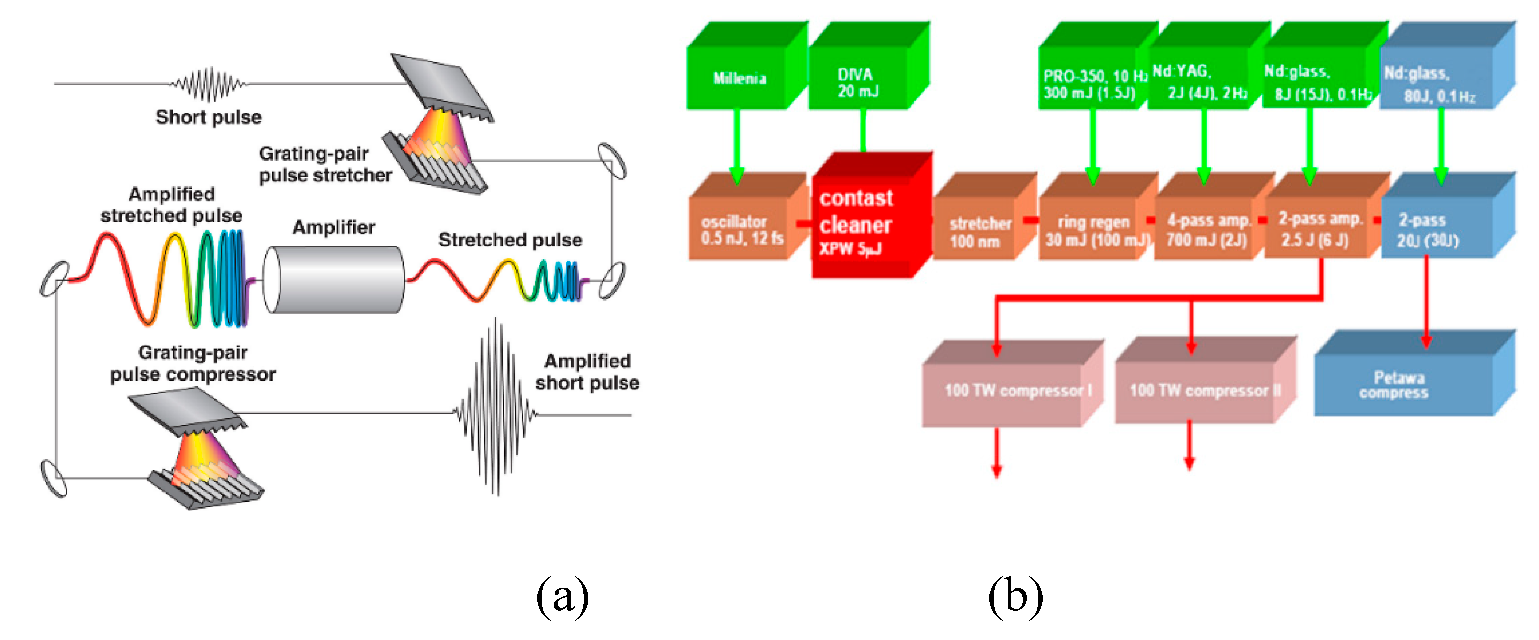
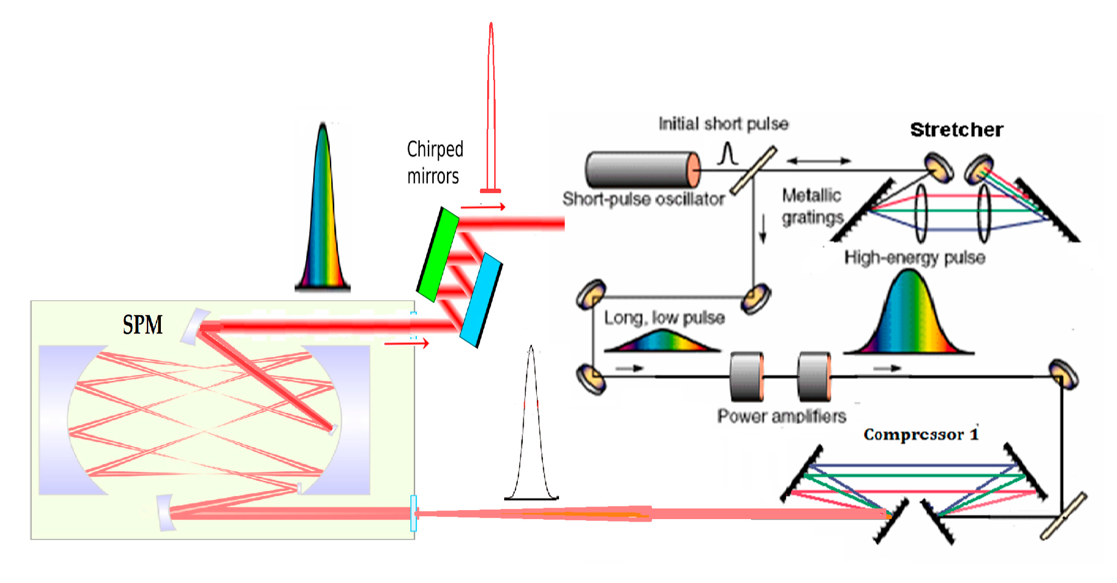
general scheme of the CPA laser system is presented on
Figure 5 a.
Initiating from the Mod-lock oscillator, which
produces pulses ranging from 10s nJ to 1μJ with durations spanning from a few
ps to few fs, the beam is directed towards a stretcher. This device elongates
the pulse duration by several orders of magnitude, extending it up to the
nanosecond level. The stretcher comprises two diffraction gratings with an
optical telescope positioned between them (messed for simplicity at
Figure 5 (a)). This specific configuration of
the stretcher, proposed by Oscar Martinez in 1985 [
24],
has proven highly effective in facilitating the implementation of the CPA
method. This optical setup disperses the broad spectrum of the short pulse into
multiple narrow harmonics and routes them along different optical paths.
Specifically, it arranges the longer wavelength harmonics (red) to travel
shorter paths compared to the shorter wavelength ones (blue). Upon undergoing
double passes through the stretcher, these harmonics reassemble into a single,
elongated pulse with what is termed a positive chirp, where the red wavelengths
precede the blue ones. In reality, the discretization of the continuous
spectrum into separate harmonics was carried out for the sake of simplicity.
For a more thorough understanding of the stretcher's operation, refer to [
25]. As demonstrated earlier, the longer pulses
possess a higher damage threshold for optics, enabling a significant reduction
in the aperture of the optical elements to a reasonable level, even for high
energy applications. These elongated pulses are then directed, following
stretching, to a chain of multipass amplifiers where they accumulate the
required energy. Subsequently, from the final amplifier, the large energy long
pulses are directed to the compressor, comprised of either two or four
diffraction gratings as depicted in
Figure 5a.
The compressor, as described in [
26], executes
the reverse procedure of the stretcher. It guides the red harmonics with longer
wavelengths along longer paths and the blue ones with shorter wavelengths along
shorter paths, culminating at the compressor output into a short pulse.
Ideally, this pulse equals the initial one but now possesses significantly
higher energy, leading to an exceptionally high pulse power.
Each element of this scheme has undergone
modifications and improvements since 1985. Here, we'll outline the main trends
of this technology. The general modifications applied to two key components of
the CPA system, namely the stretcher and compressor, primarily involved
enhancing pulse stretching [
27], improving the
quality and size of the gratings [
28], and
achieving better alignment and conjugation between the stretcher and compressor
[
29,
30,
31].
Concerning the oscillator and amplifiers, their
initial designs were centered around Nd:glass and Nd:YAG crystals [
32,
33], which typically exhibited a luminescent
spectral bandwidth of 0.5 - 15nm FWHM. These oscillators could generate pulses
with durations of several hundreds of femtoseconds. However, to achieve the
desired output power of 1PW from these laser systems, amplification to the
kilojoule energy level was necessary.
The adoption of Ti: Sapphire crystals [
34] as the gain medium for CPA brought about a
significant reduction in pulse duration, thanks to their much broader
luminescent spectra spanning up to 200 nm, capable of supporting pulse
durations as short as 5fs. Additionally, these crystals possess several unique
properties such as high thermal conductivity for effective heat extraction, low
thermal expansion, and impressive hardness, rendering them suitable for use in
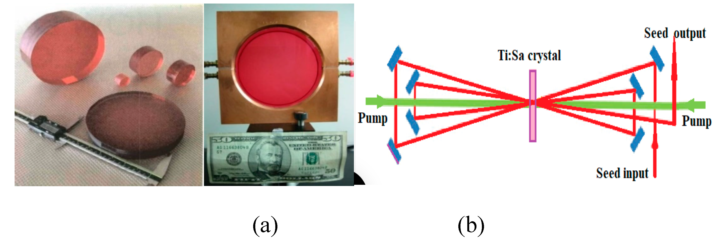
laser oscillators and amplifiers. With the capacity to produce large-aperture
crystals above 20cm [
35] in diameter (
Figure 6 a), they have become the workhorse for
amplifiers in CPA laser systems, ultimately facilitating the achievement of the
current record output power of 10PW [
10].
However, achieving this extraordinary result
demanded numerous technological improvements in laser amplifiers. For instance,
generating the energy required for a 10PW pulse power approaches several
hundreds of joules, necessitating crystal apertures of tens of centimeters in
diameter. Consequently, the gain in the transverse direction far exceeds that
in the longitudinal direction, considering the typical crystal thickness of a
few centimeters. Thus, extracting stored energy by the amplified pulse (seed)
requires a multipass optical scheme and takes considerably longer time compared
to the pulse duration (approximately 100ns for a 1ns pulse). A typical scheme
of a multipass Ti:Sa amplifier is illustrated in
Figure 6b.
The initial method of amplification involved the
full energy crystal pumping before the arrival of the seed pulse, resulting in
substantial energy losses due to amplified spontaneous emission (ASE) and/or
transverse parasitic generation.
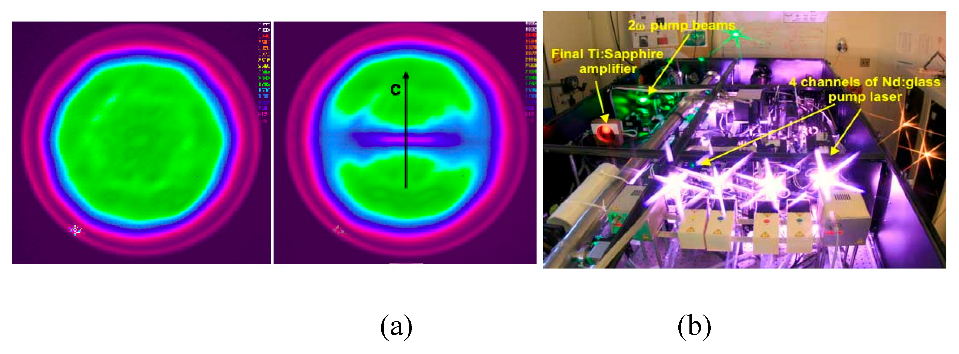
Figure 7a
illustrates the luminescence of the pumped Ti:Sa crystal before and after the
onset of parasitic generation.
One of the methods employed to mitigate these
substantial losses was the cladding of the side surface of the crystal with a
material having a refractive index equal to that of the crystal, thereby
preventing light reflection back into the crystal material and minimizing
further losses [
36]. However, this approach
proved insufficient for truly large crystal apertures due to the significant
transverse gain. In 2003, a new method was proposed to address this challenge,
namely the optimization of timing between crystal pumping and pulse extraction [
37,
38,
39,]. This method, known as Extraction During
Pumping (EDP), enabled the optimization of the energy required for pumping
before and after each seed pulse pass, thereby reducing losses. First time this
method was tested with the Hercules laser system in the Centr for Ultrafast
Optical Science (CUOS) of University of Michigan.
Figure 7b shows the final amplifier of The
Hercules during shot. The laser system reached the record intensity of 2*10
22
W/cm
2 in 2008 [
40]. With EDP, it
became possible to extract up to 0.6 kJ from large-aperture Ti:Sa crystals with
diameters of up to 25cm [
39].
Another type of amplifier utilized in high-power CPA systems is the Optical Parametric Amplifier (OPA) or Optical Parametric Chirped Pulse Amplifier (OPCPA) [
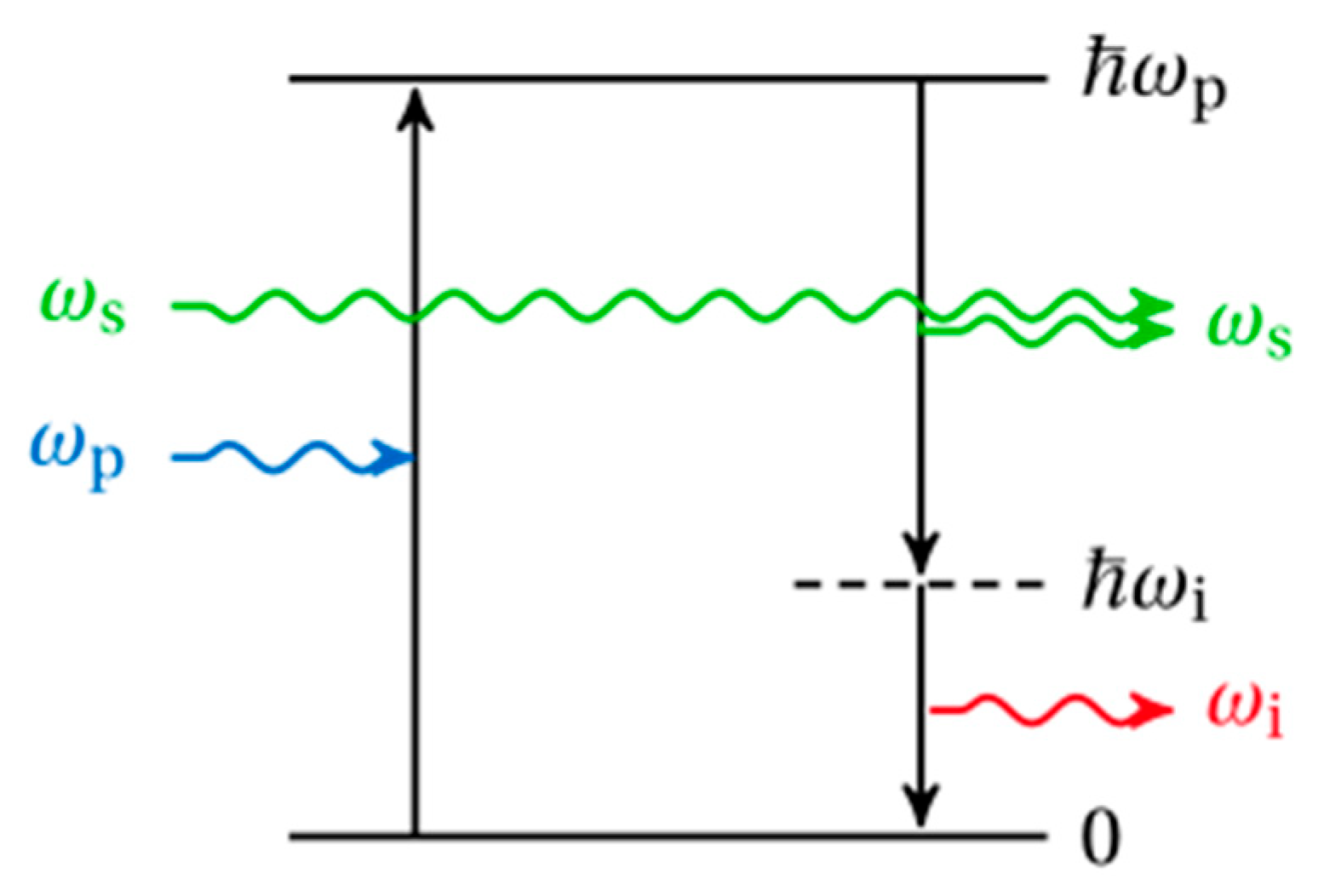
41]. Unlike traditional laser amplifiers, OPAs leverage nonlinear interactions between pump and seed pulses within crystals. In the parametric amplification process, the high-energy quantum state of the crystal, excited by pump photons, undergoes decay stimulated by a seed photon (see
Figure 8). This decay leads to the emission of another seed photon and an idler photon, facilitated by the virtual energy level between the excited and lower states. All three photons adhere to the laws of energy and momentum conservation, necessitating their efficient amplification within a certain distance of the crystal [
42]. To amplify pulses with broad spectral bandwidths, the initially collinear incidence of pump and seed beams on the crystal surface has been replaced with a noncollinear approach (NOPA), enabling the maintenance of synchronization conditions for these broad spectra [
43]. NOPAs offer several advantages over traditional laser amplifiers for their applications in CPA systems, such as improved temporal contrast and energetic efficiency. However, OPCPA systems face challenges, including the necessity for high-quality pump pulses and precise synchronization with the seed pulse, which can be considered disadvantages. It's worth noting that the output power of OPCPA systems now approaches that of laser CPAs [
44]. Used for OPA the KDP and DKDP crystals can be grown with large size clear aperture up to 500 mm diameter, allowing amplification of nanosecond stretched broad-bandwidth laser pulses at kJ-energy-level. Looking ahead, there are ambitious plans to further increase power output, with projects aiming for up to 50 – 100 PW, as demonstrated by initiatives like the OPCPA system development project referenced in [
45,
46].
Industrial, medical, and numerous scientific applications of CPA lasers necessitate a substantial increase in the pulse Repetition Rate (RR), or in other words, the average power. However, the RR of existing high peak power laser systems is typically low, often limited to a few Hz or less [
47]. The primary obstacle to significant RR raising is the escalating heat generation in amplifiers, attributed to the quantum defect, which creates an energy difference between pump and seed photons.
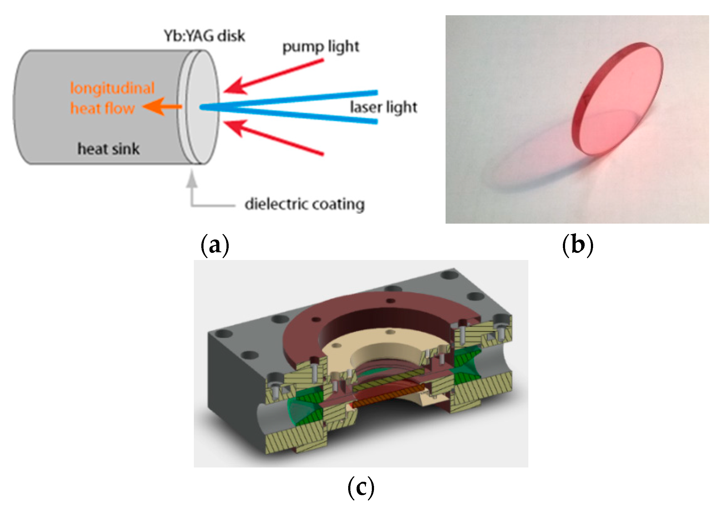
The Thin Disc (TD) geometry of laser amplifier active media, such as Yb:YAG, has proven highly effective for heat dissipation, enabling remarkable achievements in laser power. Continuous Wave (CW) regimes have achieved output powers of up to 10s kW [
48], while in master oscillator - power amplifier (MOPA) systems, several Joules of energy per pulse and high average power have been attained [
49].
The typical scheme of TD amplifier is shown on
Figure 9 a, the heat is extracted through the largest face of the crystal for efficient and uniform cooling, in opposite to the conventional side-surface heat extraction. The very high thermal conductivity Ti:Sa crystal with combination of TD technology allows to increase this effect, preventing the overheating of the laser crystals and, thus eliminating the beam thermal distortions and possible crystal damage even for an extremely high average power operation regime [
50,
51,
52,
53,
54].
Figure 9b,c demonstrate consequently TD 35*3 mm Ti:Sa crystal and holder with both large surfaces direct contact water chilling.
However, the TD crystal shape represents just one possible geometry for the final amplifier in laser systems, and it may undergo changes depending on the desired output parameters. In paper [
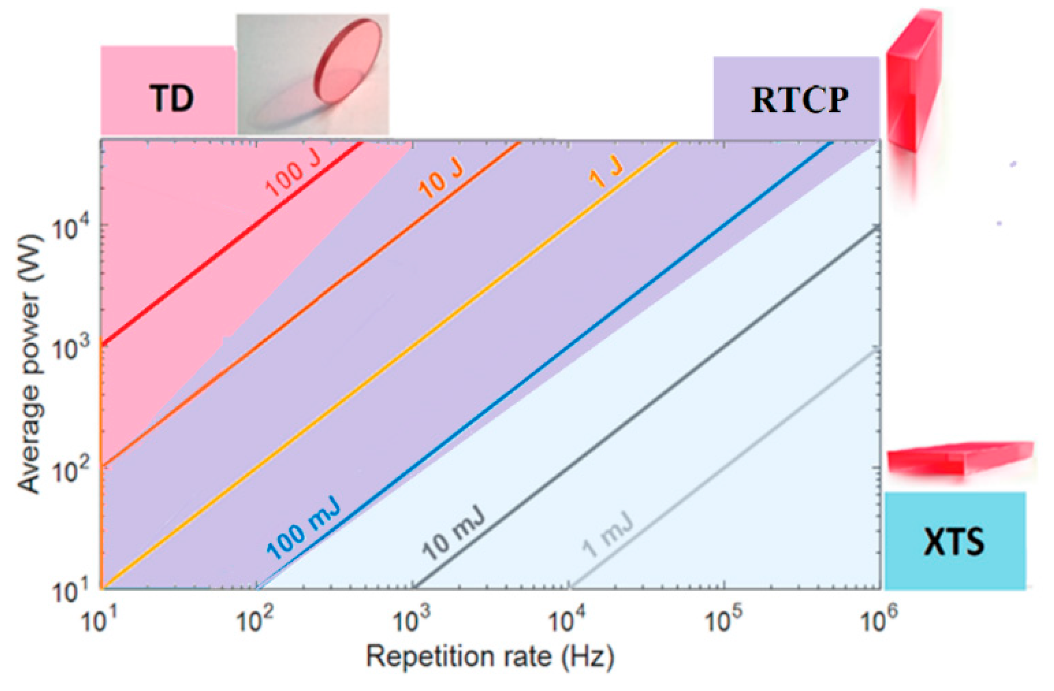
54], simulations were conducted to determine the maximal achievable pump fluence of the amplifier crystal, which was found to depend on the repetition rate (RR). These simulations also highlighted the effect of pump fluences on the selection of crystal shape.
Figure 10 illustrates the relationship between the required output average power and the repetition rate (RR), delineating preferred areas of usage for different Ti:Sa crystal configurations such as Thin Disc (TD), Rectangular Thin Crystal Plate (RTCP), and Cross Thin Slab (XTS). As depicted, the TD crystal configuration is well-suited for systems with an RR below a few hundred Hz, especially if an output pulse energy above 10 Joules is required (red area) [
50,
51]. Conversely, the RTCP geometry demonstrates superiority for Ti:Sa amplifiers operating at an RR above 1 kHz, covering an energy range of 0.1–10 J (violet area). Lastly, the XTS crystal shape emerges as the preferred choice for amplifiers operating at high RR levels above 1 kHz but with a low energy per pulse below 100 mJ (blue area) [
52,
53].
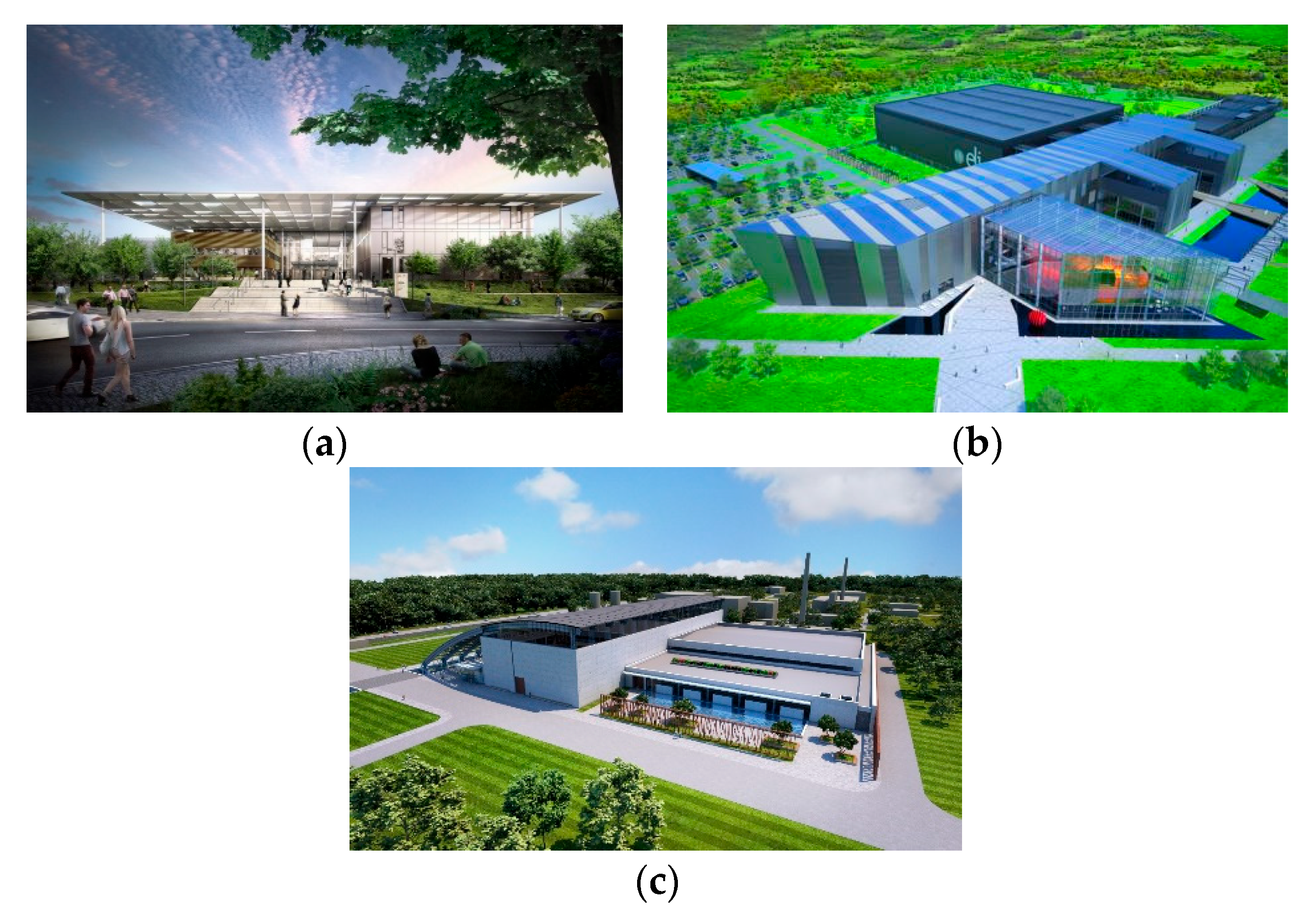
The laser systems utilizing the CPA technique have recently achieved remarkable results and continue to show significant potential for further development. Several facilities have been constructed or are currently under construction. One of the pioneering and notable projects in this field is the Extreme Light Infrastructure (ELI).
Under this project, three laser centers were developed in Eastern Europe (see
Figure 11): ELI-Beamlines in the Czech Republic [
55], ELI-ALPS in Hungary [
56], and ELI-NP in Romania [
57]. These three pillars of ELI include several petawatt-class lasers: ELI-ALPS (HF) Ti:Sa system with a peak power of 2 PW and a pulse duration of 17 fs; ELI-BEAMLINES (L3) Ti:Sa laser with a 30 J pulse energy, 1 PW peak power and a pulse duration ~ 30 fs; ELI-BEAMLINES (L4) Nd: Glass lasers of 2kJ / 10 PW/ 130fs; and ELI-NP with two channels Ti:Sa lasers of 300 J / 10 PW each.
Two other notable high-power laser systems are the Chinese system with an output power of 10 PW [
58] and the South Korean system with an output power of 5 PW. The latter recently achieved the highest intensity of 2×10
23 W/cm
2 [
59].
