1. Introduction
1.1. V-Model
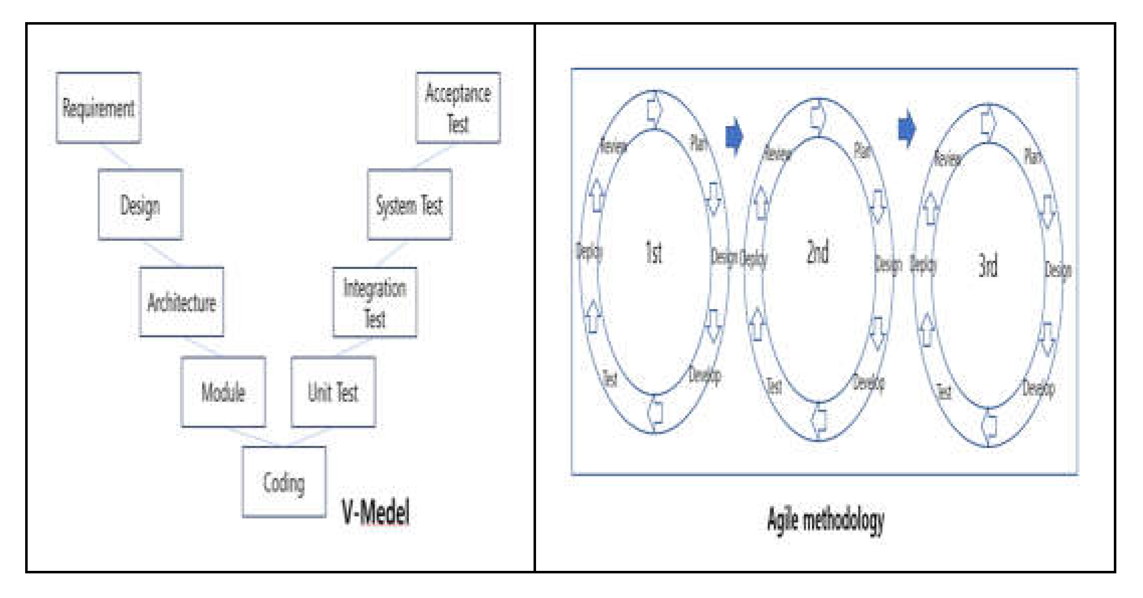
It addresses background of software development lifecycle and methodology. Software development lifecycle models include the waterfall model, V-model, and Spiral-Model etc. The V-model is an extension of the waterfall model and is commonly used the development the software in safety-related systems. It emphasizes the importance of early planning and verification activities for each software development life cycle. Unlike the waterfall model, the V-model processes in a linear downward direction at the form an alphabetical V, as shown in
Figure 1. The V-model maps the relationship between each phase of the development lifecycle and the corresponding phase of software testing on both sides of the V-shape. The V-model is a well-organized model to work through each phase of software development with detailed documentation. It is also a good model to start testing activities, such as test design, in the beginning of a project rather than after coding, which can be cost-effective approach overall project by saving of cost and time.
1.2. Agile Methodology
Agile methodologies, such as Scrum, are used by many developers in software development due to their flexibility and iterative characteristics. In the beginning of project, Agile methodologies can be applied to safety-related software systems to solve problems and errors by demonstrating and iterating on issues related to traceability, documentation, and formal verification in advance. Agile methodology is a flexible approach for developing software quickly and modifying it to meet user needs and changing circumstances. (
Figure 1)
The proposed JY(JangYeol) methodology in this paper modifies and transforms the structural analysis and structured design methodology of Yourdon/Demacro [
1] to a little combine the development and verification processes by interaction them, and defines detailed activities for each role in the development and verification of safety-related software referenced by NUREG-0800/BTP-14. By defining detailed activities for each role in the development and validation of safety-related software as required by NUREG-0800/BTP-14, it will be easy for preliminary conformance assessment for license applications to regulatory body.
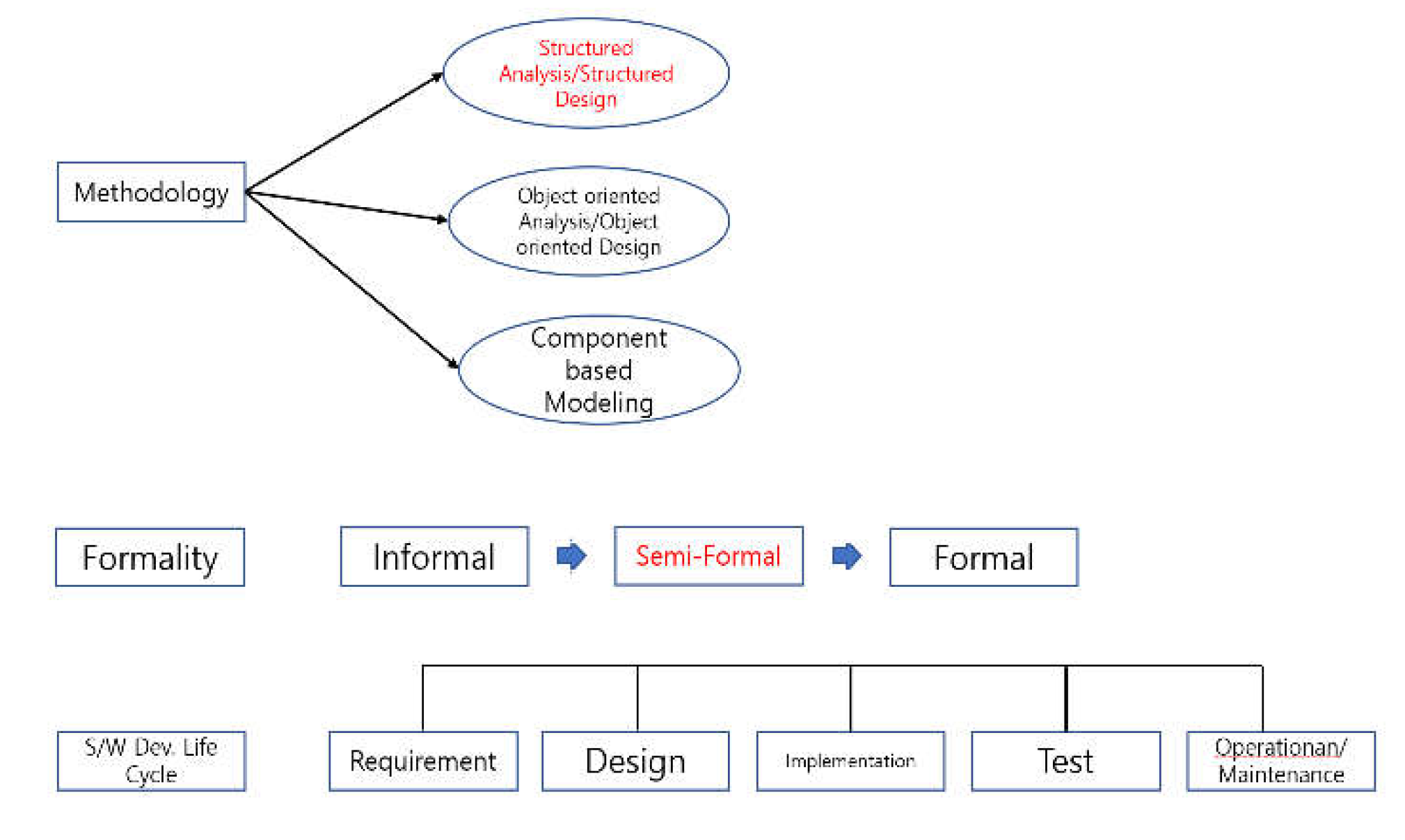
Figure 2 illustrates the classification of the JY development and verification methodology proposed in this paper. It belongs to structural analysis and structured design and, it corresponds to semi-formal in terms of methodology classification. In terms of simplification and standardization principles, we set up the analysis phase (requirements), design phase, implementation phase, test phase, and operation and maintenance phase.
1.3. Proposed JY- Development Methodology and Its V&V Activities
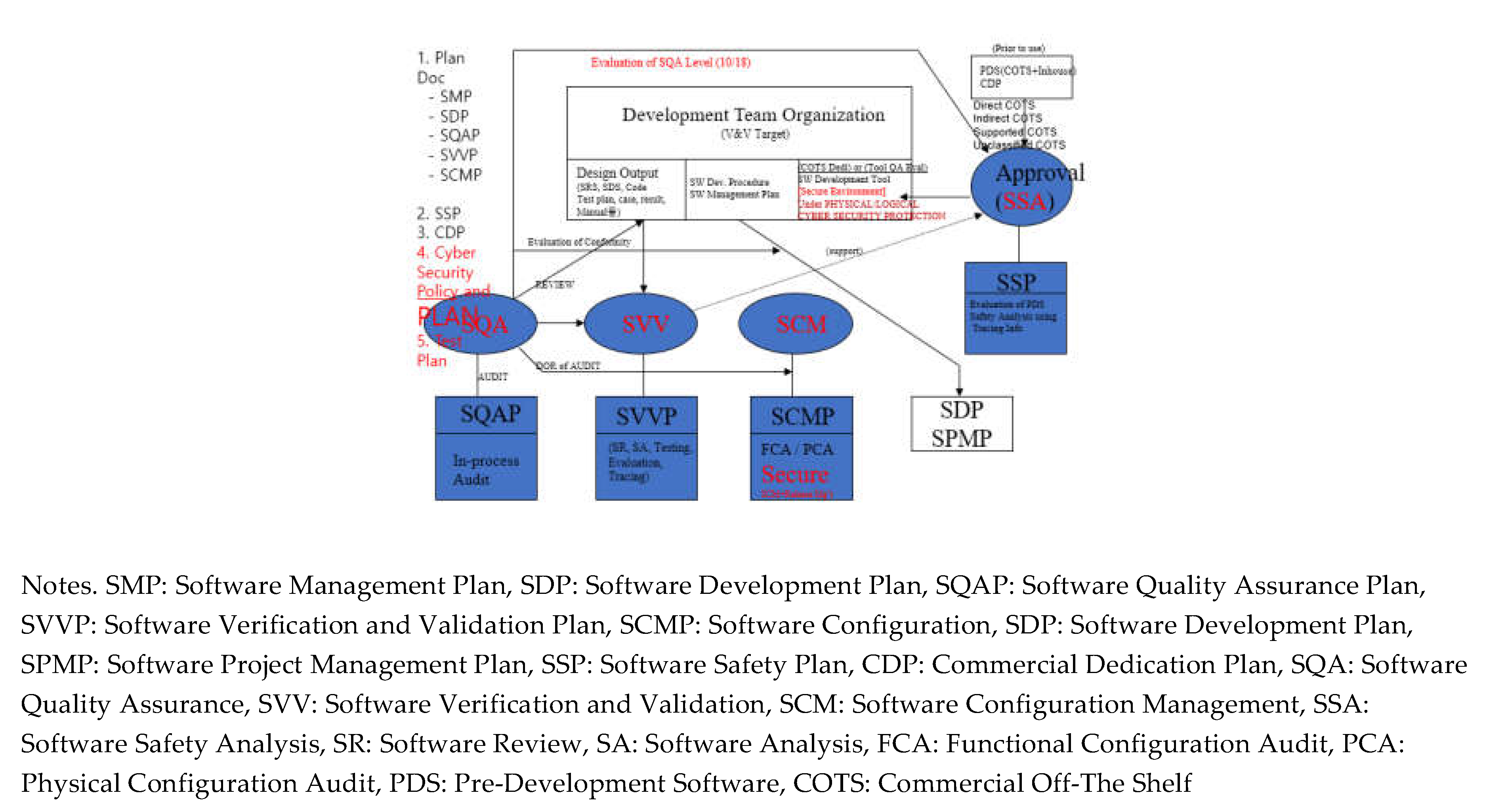
A safety-related system is a system whose failure or malfunction may result in one or more outcomes, which are death or serious injury to people loss or severe damage to equipment/property environmental harm. Examples of such systems include elevator systems, medical device systems that use irradiation, process control systems in chemical plants, aircraft control systems, and nuclear reactor protection systems. Especially, this paper proposes a development methodology and its verification methodology that can be used to develop software for small digital devices used in safety-related systems, such as digital indicators, graphic recorders, M/A (Manual/Auto) stations, optical modems, and loop controllers. Activities in the development of safety-related software produce design outputs (plan, requirement specification, design specification, implementation specification, test plan, test procedure, test result report, and operations manual) along the software life cycle as shown in
Figure 3. Activities on the verification and validation side include review, audit, testing & evaluation, software safety analysis, configuration management, and Commercial Off-The Shelf (COTS) dedication. This paper describes the JY-methodology and its V&V activities for application to Safety-related Systems. It is mainly described from the perspective of software development and verification methodology process, excluding equipment qualification (i.e., environmental, seismic, and EMI/RFI), which is the field of hardware qualification. V&V tasks for the development of safety-related software and the corresponding verification methods should be considerate information engineering process from the beginning of initial development to final completion. The development and verification and validation methodology shall be consistent with NUREG-0800/BTP-14, IEEE 7-4.3.2, and IEEE 1012, which are the digital software licensing criteria for nuclear power plants, and have been considered to satisfy their topical issues. Their contents are summarized as follows, and the detailed activities are shown in
Figure 3.[
2]
Setting the scope of development and V&V
Acceptable framework criteria based on international standards
Relevance between development and the V&V organization and other organizations involved.
Independence requirements
V&V Task entrance and exit criteria
V&V Material, Configuration Management (CM), Packing policy
2. Setup Development and Verification Activities for Safety-Related Software of Small Digital Devices
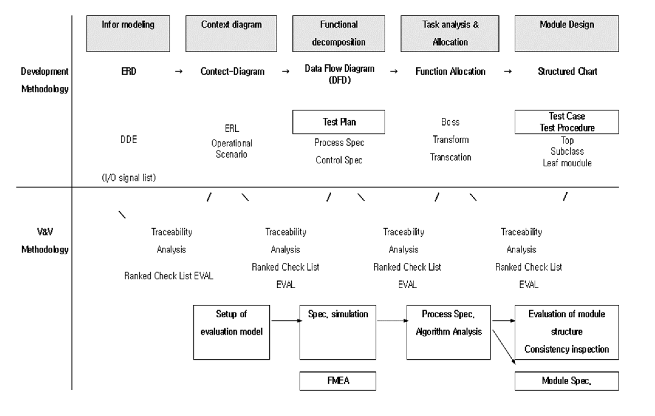
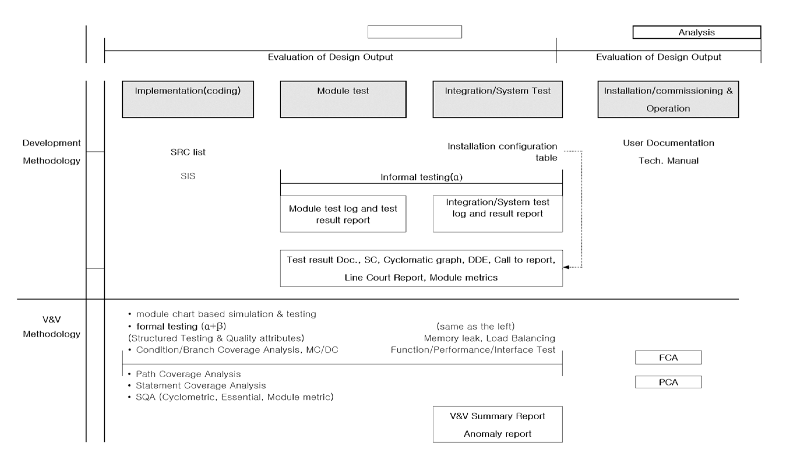
Safety-related software systems should be designed to ensure the reliability, safety, and quality of the system based on simplification, standardization, and specialization. These systems must be supported by software engineering processes such as development methodologies and verification methodologies that adhere to strict requirements and criteria to minimize the probability of failure. In this paper, a strict development and V&V methodology is defined according to the software life cycle, and the JY-methodology is proposed to satisfy traceability by separating the developer’s activities from the verifier’s activities to generate verifiable outputs at each software development life cycle as shown in
Figure 4. The developer’s process defined in this paper are the ERD-Context Diagram-functional decomposition process and operational scenario in the requirement phase. In the design phase, task analysis and task allocation and module design activities are defined. In the implementation phase, it was recommended to utilize essential coding guidelines for safety. Verification and Validation activities defined the developer’s activities to include the left-hand side of the V-shape to include the test phase, installation and commissioning phase, and operation/maintenance phases. The developer’s testing was characterized as informal testing, while formal testing ac-cording to standards, plans, and procedures was categorized as a verifier activity. The detailed process of their development and verification activities is shown in
Figure 4 and
Figure 5. The development methodology is based on structured analysis and structured design, which have been proven in the software engineering field for a long time. The development methodology is as follows: Information modeling -> Context diagram -> Functional decomposition -> Task analysis & Allocation -> Module design -> Implementation -> Module test -> Integration/System test -> Installation/commission & operation. (
Figure 4 and
Figure 5) The verification method according to the development methodology is verified by Traceability Analysis and Ranked Check List method from Information modeling to Module design. At this time, FMEA related to safety is performed at the design phase. In the test phase, independent testing is performed according to the verification guidelines from the informal testing performed by the developer separately. The developer performs informal testing and the verifier performs formal testing. The main difference between them is that informal testing is performed without formal test criteria and formal test procedures. Formal testing means to perform test according to formal test criteria and test procedures. During formal testing, the verifier tests the module to satisfy statement coverage, condition/decision coverage, and Modified Condition/Decision Coverage (MC/DC). In the integration test phase, memory leak test and load balancing test are performed. System tests include interface tests, functional tests, and performance tests. The main difference between the tests performed by the developer and the verifier is that the verifier’s tests are performed independently of the developer, according to the verification criteria and procedures, and are formally tested with additional test cases created by the verifier. Detailed processes are shown in
Figure 4 and
Figure 5 respectively.
Select the candidate Entity and Attribute:
NPP, sensor_detector, mechanic, registration etc
o Define the Data Dictionary (DDE)
- NPP = @plant_no + model_type + construction_date + life_span
- sensor_detector = @sensor_id + location + timing_tag etc
o Define the Relationship
- 1 “exactly one”
- N “one or more”
- 0<=N “zero or more”
- 0<=N<=1 “at most one” |
3. JY Development Methodology Process
The most important part of the development process is information modeling (data modeling). In information modeling, an E-R Diagram (Entity-Relationship Diagram) is created and data dictionary is created. The data dictionary is commonly used to maintain consistency throughout the all of the lifecycle. Some kinds of tools can be used to create databases based on E-R diagrams, and the creation of the database can be automated. The data modeling is the basis of any design. Here’s a simple example.
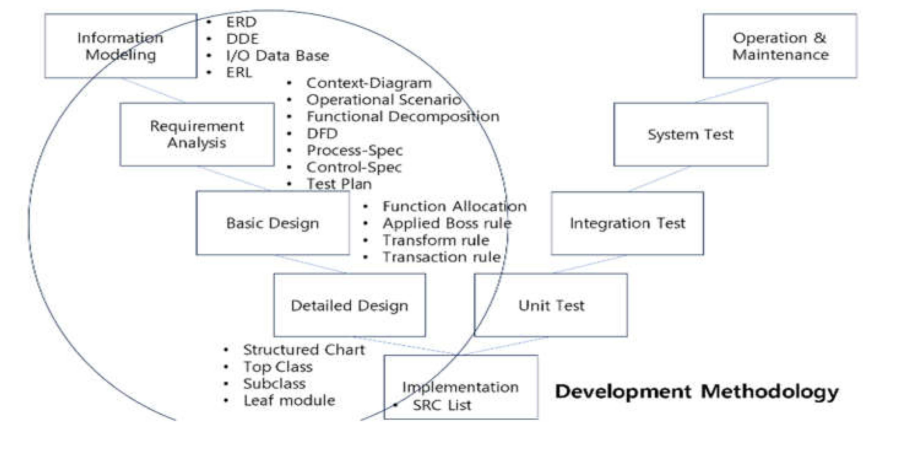
The following process creates an Event-Response List (ERL) table. For every event in the target system you want to develop, create Event[condition]/Response in the form of input, output, and storage (memory) in the form of Trigger/Action. Using the ERL create a Context Diagram so that you can grasp the means and goals you want to overall development status at a glance. Context Diagram defines the marginal environment such as input, output, etc. and creates an operation scenario. The Context Diagram is the beginning of the requirements phase, which includes functional analysis. Through functional analysis, control specification and process specification are defined, and later, a test plan is created for system testing. The hierarchical functional decomposition is done in a top-down format with three to five layers (not more than seven layers). Each function reuses design data from the previous information modeling (E-R Diagram). The design phase assigns the features defined in the previous requirements phase to tasks. This can be a 1:1 assignment or a M:1 assignment. Task allocation is done through task analysis such as transform rules and transaction rules. When designing, we define the top class, sub-class, and the lowest leaf-module, and design the leaf-module to be the smallest unit. Leaf-modules are represented by pseudo code or algorithms. In the implementation phase, a programming language is selected to generate the source code. It is recommended to use a programming language that is already proven in safety-related system. Examples include Ada, C, and Pascal etc. It is important to note that scripted languages should never be used in safety applications because of vulnerabilities. The left part of
Figure 6 is the JY-development methodology, which is a reference of the Yourdon/Demacro [
1] structured analysis and structured design methodology proposed in this paper. Here, the unit test, integration test, and system test are performed by the developer, but as an informal procedure, and all formal test/verification procedures are performed by the verification and validation team according to the test plan and test procedure.
4. JY Verification and Validation Methodology Processes
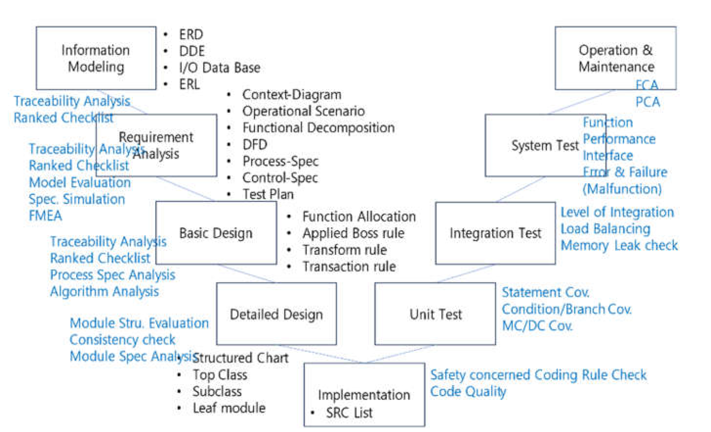
The verification process corresponds to each development methodology process. The blue color part in
Figure 7 is the verification methodology that corresponds to the development methodology. It should be performed in all software development life cycle activities. At the top level, it is reviewed with a ranked checklist and traceability analysis is performed. In the requirements phase, HAZOP-based safety analysis is performed, and FMEA is performed after the design phase. In the implementation phase, code inspections are performed based on safety-related source code rules. Test and verification after the implementation phase consist of module/unit test, integration test, and system test.
The pass/fail criteria for V&V in the test phase is that the module/unit test must satisfy statement coverage, condition/decision coverage, and MC/DC coverage. The pass/fail criteria for the integration test is to verify interface errors between the modules/units being integrated, and it is important to maintain load balancing so that the degree of integration is not skewed to one side. During the integration process, it is essential to verify that there are no memory leaks. During the system testing phase, error-based malfunction tests are performed to verify functionality, performance, and interfaces and to ensure that there are no potential errors. At the end of the malfunction test, the results of the FMEA are finally synthesized and an incremental safety case demonstration is performed. After the safety case demonstration, the Functional Configuration Audit (FCA) and Physical Configuration Audit (PCA) are performed and the verification is done finally (
Figure 7).
Detailed Process with V&V Tasks
The definition of V&V activities from a technical point of view based on the developer’s deliverables along the software lifecycle is shown in
Table 1. V&V consists of review & audit, analysis, testing and evaluation. The most important thing in software verification activities is to perform COTS dedication for development tools and verification tools in advance. In addition, safety analysis and configuration management should be performed at all software development life cycle. In
Table 1 [
2], lowercase r and lowercase a stand for review and audit, respectively, with technical support from the SVV team. A capitalized R indicates a formal review process according to the quality assurance procedure, which can be divided into the responsibilities and roles of higher-level system quality assurance and lower-level software quality assurance. Depending on its importance, configuration management can be performed under quality assurance or it can perform independently of quality assurance. Configuration management activities include performing a configuration control board and release managements. Changing management is also performed as determined by configuration control board, and configuration control and configuration baselines are managed. Safety analysis is performed throughout the entire software development life cycle, and safety analysis uses traceability information as input for the SVV team to verify the software. The main activities are traceability analysis, testing/validation, and evaluation. There are three types of audits: functional configuration audits, physical configuration audits, and in-process audits. Among them, in-process audits can be performed by the auditor on a random sample of software development life cycles. Functional configuration audits differ from physical audits in that they are performed during development activities and physical audits are performed at the end from a delivery perspective.
Software quality attributes have many different primary and secondary characteristics, such as functionality, reliability, usability, efficiency, validity, and portability. Especially, secondary characteristics belongs to Correctness, Completeness, Consistency and Traceability etc. One of the most important of these characteristics is 3C+T. In 3C+T, 3C stands for Correctness, Completeness and Consistency and T stands for Traceability. The verifier should check the 3C+T through a checklist of quality attributes from the beginning to the end of the development process. (
Table 2). Summary information in this paper is as shown in
Table 2.
5. Challenges and Recommendations
5.1. Complexity and Scale
Safety-related software systems often face challenges arising from complexity and scale. In this paper, strategies to address the challenges of modular design, code reuse, and model-driven development and verification have been described.
5.2. Certification and Compliance
Safety-related systems must comply with strict qualification/certification requirements. This paper emphasized the importance of qualification criteria and recommended strategies for their systematic development to streamline the V&V process.
6. Results
This paper concludes that the development and V&V of safety-related software systems requires a multifaceted approach that includes an appropriate development methodology and a comprehensive set of verification and validation techniques. Therefore, the use of JY-development methodology and its verification methodology facilitates the assessment of licensee conformance in safety-related systems. It is an alternative approach to addressing emerging issues and challenges in safety-related software development and verification, and requires continuous improvement and adaptation. In the future, I will study safety-critical software development methodology and its verification and validation in details.
Acknowledgments
This work, described herein, is being performed for “Development of Regulatory Methodology for Reliability Evaluation of Digital I&C Software in Nuclear Power Plants(2106027-0121-SB110)” as part of the Korea Atomic Energy Research Institute (KAERI) projects and funded by the Nuclear Safety and Security Commission
References
- http://online.visual-paradigm.com, DFD Using Yourdon and Demarco Notation.
- Jang-Yeol Kim, Qualification Process for Nuclear-oriented Computer Code, JDCS, 2021, vol.22, no.1, pp. 191-197(7 pages). [CrossRef]
- Jang-Yeol Kim, J. R. Keum, I. S. Oh, S. R. Koo, G. K. Choi, J. K. Lee, Tailoring Approach of Verification and Validation Activities by Safety Class based on IEC/IEEE Harmonization, Korea Society of Industrial Information Systems, Spring Conference in 2022.
- Jang-Yeol Kim, Jong-Gyun Choi, Trend Analysis of Harmonization of IEEE/IEC Standards, 2022 Korea Society of Industrial Information Systems, Autumn Conference, in 2022.
- Jang-Yeol Kim, Jong-Gyun Choi, Application of Software Safety Mechanism in Small Digital Devices, Korea Society of Industrial Information Systems, Spring Conference in 2023.
- Jang-Yeol Kim, The Method of Software Safety Mechanism based on IEC 61508 and IEC 60880, 52th Korea-Japan International Conference in 2023.
- Progress in Nuclear Energy, Volume 99, August 2017, Pages 86-95, “Harmonization of IEEE 1012 and IEC 60880 standards regarding verification and validation of nuclear power plant safety systems software using model-based methodology”.
- G. Johnson. (2001). Comparison of IEC and IEEE Standards for Computer-Based Control Systems Important to Safety, U.S. Department of Energy, Lawrence Livermore National Laboratory.
- IEEE 7-4.3.2-2003, IEEE Standard Criteria for Digital Computers in Safety Systems of Nuclear Power Generating Stations.
- IEC 61513, Edition 2.0, 2011-08, Nuclear power plants – Instrumentation and control important to safety – General requirements for systems.
- NUREG-0800, Standard Review Plan for the Review of Safety Analysis Reports for Nuclear Power Plants: LWR Edition (NUREG-0800, Formerly issued as NUREG-75/087), Chapter 7, Instrumentation and Controls, October 02, 2023.
- Nuclear Safety and Security Commission, NSTAR-21NS42-216, Analysis of Code & Standard (IEEE/IEC) Schemes for the Software Reliability of Digital I&C Systems.
- Nuclear Safety and Security Commission, NSTAR-21NS42-217, Analysis of Overseas Cases for Software Reliability Regulation based on IEC Standards.
|
Disclaimer/Publisher’s Note: The statements, opinions and data contained in all publications are solely those of the individual author(s) and contributor(s) and not of MDPI and/or the editor(s). MDPI and/or the editor(s) disclaim responsibility for any injury to people or property resulting from any ideas, methods, instructions or products referred to in the content. |
© 2024 by the authors. Licensee MDPI, Basel, Switzerland. This article is an open access article distributed under the terms and conditions of the Creative Commons Attribution (CC BY) license (http://creativecommons.org/licenses/by/4.0/).
