1. Introduction
Simultaneous localization and mapping (SLAM) is a technique for mobile robots equipped with sensors to estimate their motion state and simultaneously model their surroundings in an unknown environment [
1]. Nowadays SLAM has become a hot research issue in mobile robotics. Visual SLAM uses cameras as sensors. Compared to other sensors, cameras are less expensive, lighter in weight, easy to install on hardware, and capable of acquiring rich environmental information. Therefore, visual SLAM has been rapidly developed in the field of SLAM.
There are several landmark research results within the field of visual SLAM. Andrew J. Davison et al. [
2] proposed the MonoSLAM, which allows for real-time construction of sparse environment maps as well as localization of the robot's position and orientation and was the first to use the Extended Kalman Filter (EKF) method for the implementation of a monocular SLAM. Georg Klein et al. [
3] proposed the Parallel Tracking and Mapping (PTAM) algorithm in 2007, which means that the two tasks of tracking and mapping are divided into independent tasks and processed in two separate threads, and became the first algorithm for multi-threaded processing of SLAM. Newcombe et al. [
4] proposed the DTAM, a monocular SLAM algorithm based on the direct method. the method utilizes frame rate alignment of the entire image to estimate the camera's 6 degrees of freedom bit position relative to a dense map and can achieve real-time results on GPUs. Forster et al. [
5] proposed a visual odometry based on a sparse semi-direct method in 2014 –Semi-Direct Visual Odometry (SVO). The system runs fast, reaching more than 100 frames per second even on low-end computing platforms, satisfying real-time requirements. The Large-Scale Direct Monocular SLAM (LSD-SLAM) [
6] proposed in the same year uses the direct method to extract feature points without computing feature point descriptors, and can also construct semi-dense maps. Direct Sparse Odometry (DSO) [
7] is a monocular camera visualization navigation system proposed by Engel et al. in 2017, which is built using direct and sparse methods without detecting and describing feature points. The Stereo Parallel Tracking and Mapping (S-PTAM) [
8] is a binocular visual SLAM system based on the PTAM method, which utilizes a binocular camera for initialization, avoiding the difficulty of monocular initialization.
The ORB-SLAM [
9] is a family of monocular SLAM algorithms based on ORB feature points, first proposed in 2015. The algorithm adopts a keyframe-based approach and divides the system into three threads: tracking, mapping, and loop closing. The ORB feature points are used for feature extraction and matching, sparse map creation, and location identification. Due to its high localization accuracy and real-time operation, the ORB-SLAM family has attracted much attention in the SLAM field. The ORB-SLAM2 [
10] proposed in 2017 supports SLAM systems for monocular, stereo, and RGB-D cameras, and it can work in real-time on CPUs. The ORB-SLAM3 [
11] proposed in 2021 supports the use of various data sources such as vision, vision plus inertial, and hybrid maps. It can perform calculations on monocular, binocular, and RGB-D cameras on the pinhole or fisheye models for real-time computation. In addition, the ORB-SLAM3 supports deep learning and GPU acceleration to speed up the system's processing speed and operational efficiency.
In addition to sparse and semi-dense maps, some systems can build dense maps, e.g., ElasticFusion [
12] is a technique for 3D dense reconstruction that uses a surface element model called surfel. For RGB images, ElasticFusion computes the position by using color consistency constraints, while for point cloud data, an iterative nearest-point approach is used to compute the position. This approach enables efficient position estimation and 3D reconstruction, while also maintaining accuracy and robustness in complex environments. The Kinect Fusion [
13] is the first Kinect-based SLAM algorithm that builds dense 3D maps on the GPU in real time. The algorithm utilizes only the depth information acquired by the Kinect camera to compute the positional pose and build an accurate map model of the environment. The Real-Time Appearance-Based Mapping (RTAB-Map) [
14] is one of the classic programs for RGB-D SLAM. It could build point cloud maps and triangular grid maps and its program is available from the ROS system.
Although the application of visual SLAM technology for localization and navigation has had many research achievements in recent years, there are still many problems and challenges. It has real-time performance in simple environments such as static, rigid, insignificant lighting changes or no interference from high-speed moving objects and can generate maps in a short time. However, in complex scenes, robots are often disturbed by various noises when observing the external environment, such as indoor dynamic environments, changes in the camera observation angle, and changes in lighting, etc. These disturbances may lead to errors in the visual localization of the robots or incorrectly constructed environmental structures, which has a detrimental effect on visual navigation. With the significant progress made in image processing by deep learning in artificial intelligence, there has been related research to apply deep learning techniques into visual SLAM to utilize high-level features learned in deep neural networks for image inter-frame estimation, loop closing, and mapping.
Inter-frame estimation is a front-end process in visual SLAM, also known as visual odometry. In contrast to traditional inter-frame estimation methods, which generally require the extraction of sparse or dense features, deep learning-based methods are more intuitive and concise as they no longer require the extraction of feature points, matching of feature points, and computation of geometric relationships. Currently, DeepVO [
15] is one of the most effective and widely used visual odometry methods based on deep learning. DeepVO can infer the camera's position directly from image sequences, it uses a convolutional neural network to learn the image features, and it uses a deep recurrent neural network to learn the dynamic relationships between images.
Loop closing is a key step in visual SLAM, which determines whether a trajectory forms a loop by using sensor information to detect whether the robot has returned to a previously passed location. Loop closing is essentially a recognition problem, and traditional recognition methods use pre-designed features for matching recognition, while recognition methods using deep learning can improve recognition accuracy and efficiency by learning deep features in the image and comparing the image at the pixel level. Among them, NetVLAD [
16] is one of the excellent networks in current scene recognition, which fuses image features learned from convolutional neural networks with Vector of Locally Aggregated Descriptors (VLAD) to construct a neural network. The NetVLAD network can convert the input image into a feature vector, which is highly distinguishable and expressive and can recognize different viewpoints, lighting, and deformations in the same scene, thus improving the accuracy of loop closing.
Semantic SLAM is one of the research directions in which visual SLAM has more advanced information, which can not only establish the spatial structure of the environment but also obtain the semantic information such as position, label, etc. of any object in the environment. It can realize the construction of richer map information. Zhong et al. [
17] combined ORB-SLAM2 and SSD [
18] into a new coupling framework Detect-SLAM and proposed real-time propagation of motion probabilities of key points to solve the problem of delayed target detection threads. Semantic information is used to eliminate the negative effects caused by moving objects in SLAM. The framework aims to improve the efficiency of target detection and sensitivity to the viewpoint transformation problem, but the real-time performance of the system needs to be further optimized. Yu et al [
19] proposed a DS-SLAM scheme that improves on the ORB-SLAM2 system by combining a visual SLAM algorithm with a semantic segmentation network, utilizing SegNet [
20] to obtain semantic information in a dynamic scene, and filtering the dynamic part using motion consistency detection based on the optical flow pyramid algorithm. This method improves the accuracy of the position estimation, but the limited types of objects that can be recognized by the semantic segmentation network in this scheme restrict its application. Bescos et al. [
21] proposed the DynaSLAM scheme, also based on the ORB-SLAM2 framework, which uses the Mask R-CNN [
22] network combined with a multi-view geometric model to realize the detection and rejection of dynamic targets. The test results demonstrate that DynaSLAM has good stability and high localization accuracy under monocular, binocular, and RGB-D camera operating conditions. However, the system is difficult to run in real-time. Zhang et al. [
23] used Mask R-CNN as an instance segmentation network and PWC-Net [
24] dense optical flow network for extracting and tracking moving targets in images, which is computationally intensive and very dependent on hardware device conditions.
By comparing and analyzing the above visual SLAM algorithms combined with deep learning, the application of deep learning in visual SLAM is usually in the following modules: feature extraction, feature matching, loop closing, mapping, or adding more advanced semantic information; the neural network is used to learn more robust feature representations, to improve the validity and accuracy of the feature point extraction, to improve the ability to correlate the images as well as the accuracy of the feature matching, and to help construct a higher-quality map and give richer information, to improve the performance of the whole system.
To further improve the localization accuracy of visual SLAM algorithms for AGVs in dynamic environments and the problem of constructing semantic maps, Moreover, to balance localization accuracy and real-time performance, a semantic visual SLAM algorithm is proposed that integrates the semantic segmentation network DeepLabV3+, LK optical flow, and background restoration. this study’s primary contributions can be summarized as follows:
To reduce the interference of dynamic targets on system localization and mapping, the ORB-SLAM2 system is used as the basic framework and improved on this basis, the semantic segmentation network and optical flow method are combined to achieve the detection and rejection of dynamic targets. The feature extraction part of the semantic segmentation network is lightweight to ensure the real-time operation of the system. In addition, the time-weighted multi-frame integrated background restoration technique is used to restore the static environment occluded by dynamic objects to provide the prerequisite for system re-localization and mapping;
After eliminating dynamic targets, the static feature points are used for feature matching and camera position estimation, and combined with the semantic information output from semantic segmentation to construct semantic dense point cloud maps and semantic octree maps;
To verify the effectiveness of the algorithm in this study, it is tested in the TUM RGB-D widely used dataset and the experimental platform data, and the experimental design contains dynamic target rejection, background restoration, ablation experiments, dense map building, and semantic map building, and the experimental results are analyzed with quantitative and qualitative evaluation.
2. Relevant Theories
2.1. ORB-SLAM2 System Framework
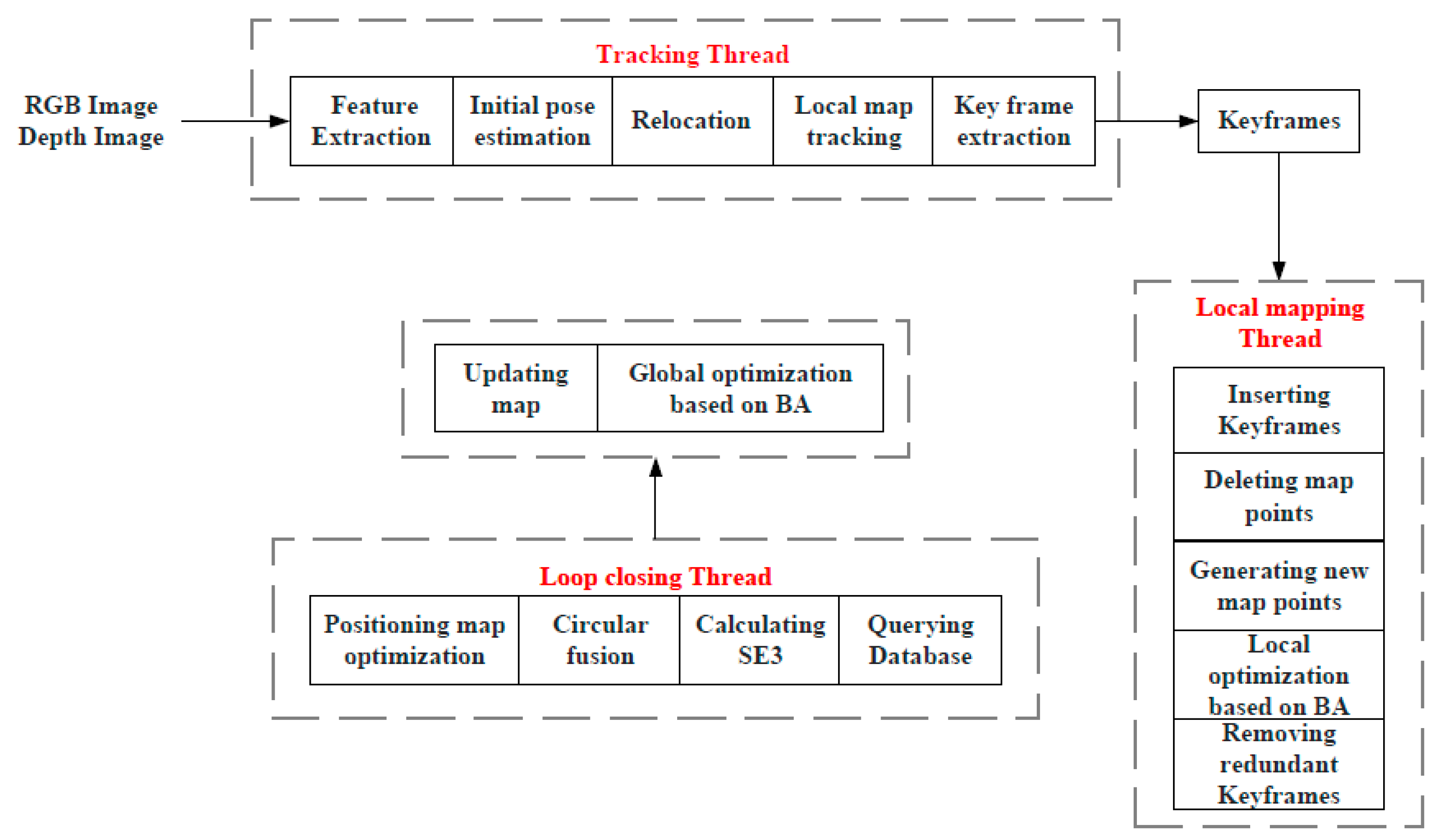
The ORB-SLAM2 system is a real-time visual SLAM system based on monocular, binocular, and RGB-D cameras capable of simultaneously estimating camera trajectories and reconstructing sparse 3D scenes. The main framework of ORB-SLAM2 is shown in
Figure 1, which mainly consists of a tracking thread, a local mapping thread, and a loop closing thread.
The Tracking thread, also known as visual odometry, works on feature extraction, feature matching, motion estimation, pose optimization, state update, and keyframe selection.
Firstly, ORB feature points are extracted from the current frame, the corresponding feature points are searched in the previous frame, and the descriptor matching algorithm is used to match the feature points in the current frame. Next, the optical flow between adjacent frames is used to estimate the camera motion, and the camera position is optimized using the BA algorithm to minimize the reprojection error. The estimated camera poses are then used to update the system state.ORB-SLAM2 manages the system state through a state machine, including initialization, tracking, loss, and relocation. Finally, the frames that contribute more to the subsequent scene reconstruction are selected as keyframes to reduce the computation and improve the system's efficiency.
The Local Mapping thread is used to build local maps containing feature points and map points observed by the camera. This thread runs in a separate thread that constantly receives new camera frames and updated camera poses from the tracking thread, and uses this data to build and update the local map. The main tasks include triangulation, map point filtering, map updating, and keyframe selection.
When new camera frames are received by the tracking thread, the local mapping thread will triangulate these feature points into 3D map points using the camera poses. To increase the accuracy of the map, ORB-SLAM2 uses a multi-view geometry algorithm to triangulate the map points and the BA algorithm to optimize their positions. A map point screening algorithm based on a greedy strategy is then used to select the most representative map points to improve the quality and efficiency of the local maps. An incremental map update algorithm is then used to update the local map based on the camera position and triangulation results each time a new camera frame is received. The update process includes operations such as adding new map points to the map, matching new map points with existing map points, and updating the positions and descriptors of existing map points. Also, the local mapping thread is responsible for selecting keyframes for global map optimization and loop closing by ORB-SLAM2.
The Loop Closing detection thread is used to detect the presence of loopbacks in the camera path and process the loopbacks. When there is a Loopback in the camera path, this thread tries to match the keyframes detected by the Loopback with the previous keyframes to correct the errors in the camera path and improve the accuracy of the map. The main tasks are loopback detection and loopback matching, and include a call to the relocation function of the tracking thread.
The ORB-SLAM2 system detects loopbacks using the Bag of Words (BoW) model. The model represents each keyframe as a bag of words, and each bag of words consists of several words. When two keyframes have similar bags of words, it is assumed that they may be different views of the same location. Loopbacks are detected by comparing the bag of words of the current frame with the ones of the history frames. When the loop closing thread detects a loopback, it optimizes the matching between the current frame and the history frame to correct the error in the camera path. Specifically, it will use the RANSAC algorithm to estimate the transformation matrix between two keyframes and then use the BA algorithm to optimize the whole loopback. The loopback detection thread can also be used for relocation when ORB-SLAM2 is unable to track the camera, such as when the camera moves to a new unexplored region. It will use the feature points of the current frame to search for historical keyframes and try to find the best matching keyframe to reposition the camera.
ORB-SLAM2 as a relatively mature visual SLAM algorithm, is currently characterized by strong real-time performance, higher accuracy, and better robustness. However, there are many problems in practical applications, especially in the presence of dynamic objects, which can lead to changes in the feature points in the scene, thus affecting the accuracy and correctness of feature matching, which can lead to an increase in localization error. In addition, the sparse mapping method of ORB-SLAM2 does not consider the semantic information represented by these pixel points. This flaw leads to the inability of ORB-SLAM2 to provide a deeper understanding of the scene and thus provide more contextual information to the robot, which affects the performance of the robot.
2.2. Semantic Segmentation Network
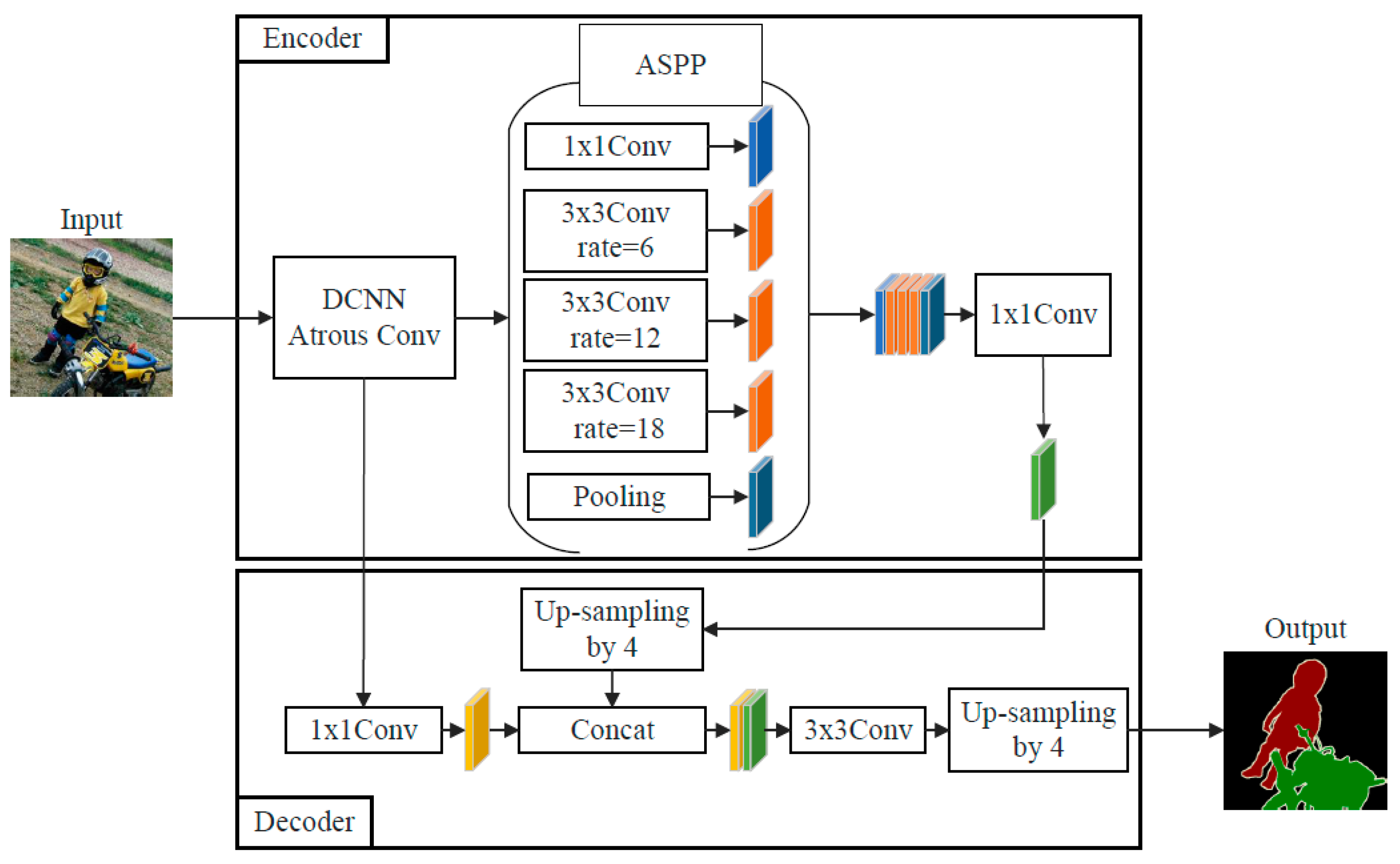
The overall architecture of the semantic segmentation network DeepLabv3+ model is shown in
Figure 2, and the main body of its Encoder is Deep Convolutional Neural Networks (DCNN) with cavity convolution, which is generally adopted from commonly used classification networks such as ResNet [
26] or Xception [
27], DCNN processed into Atrous Spatial Pyramid Pooling (ASPP) [
28] with cavity convolution, which introduces multi-scale information and reduces information loss, and DeepLabv3+ Decoder module, which further integrates the shallow features with the deeper features to improve the segmentation accuracy at the target boundary.
2.3. Detection of Dynamic Feature Points by LK Optical Flow Method
The optical flow method is a method that describes the movement of pixels between images over time. Considering the real-time nature of the system, the ORB feature points extracted by the SLAM system are calculated based on the Lucas-Kanade (LK) optical flow method. In the LK optical flow method, the image can be regarded as a function of time, and the gray level of a feature point located at at the moment t can be written as .
By the grayscale invariance assumption:
Where
is the motion velocity of the feature point in the
direction, denoted as
, respectively;
is the gradient of the feature point in the
direction, denoted as
, respectively; the change of the gray value of the feature point against time is denoted as
, and equation (1) is rewritten as:
To calculate the motion velocity
of the feature point, other constraints are added. Suppose the pixels in the same region have the same motion, i.e., take an 8 × 8 square region centered on the feature point and all 64 pixels in the region have the same motion, then the equation is:
Solve by the least squares method:
Suppose the total number of feature points within an image frame is
n, and the average motion velocity of all feature points is calculated according to equation (5) as:
Where
is the average velocity of the feature point along the
direction, respectively.
is the velocity of the
kth feature point along the
direction, respectively.
All feature points within a frame can be filtered by comparing the average motion velocity, as shown in equation (7):
where
is the judgment threshold.
2.4. Time-Weighted Multi-Frame Integrated Background Restoration Algorithm
To remove the static keyframes with dynamic disturbance, the background region occluded by the dynamic target is repaired. The current frame to be repaired is matched with all the candidate keyframes for feature matching. Then the repaired keyframes are richer in information, which is more helpful for the position estimation as well as the subsequent loop closing thread and mapping thread of the SLAM system. The proposed time-weighted multi-frame integrated background repair algorithm selects the
n keyframe images before the current frame is repaired, and sets the associated weights so that the keyframes occupy different weights at different moments. The closer to the current frame, the greater the weight, and the color information and depth information of the image is projected onto the current frame according to the feature point matching relationship, calculated as:
where
is the current keyframe after repair,
is the current keyframe without repair, and
is the keyframe at the moment
.
2.5. Construction of Dense Point Cloud Maps
Based on the rotation vectors and translation vectors obtained by estimating the camera position, the RGB-D data are converted into point cloud data, and then multiple point cloud data are stitched together to generate a point cloud map.
The stitching of the point cloud is essentially a process of transforming the point cloud. This transformation process can be described by the transformation matrix as shown in equation (9):
where
is the
dimensional rotation matrix,
is the
dimensional displacement vector;
is the
dimensional scaling vector, which is usually taken as 0 in SLAM because scaling does not exist in real environments. These matrices can be chi-square transformed into other matrices as in equation (10):
The point cloud used for SLAM mapping includes the coordinates, color, and depth information of spatial points, which are synthesized from the image frames captured by the camera. To obtain the color and depth images of the environment, an RGB-D camera can be used for acquisition, and then the point cloud is stitched together according to the camera's position information, and finally, the whole point cloud is obtained.
2.6. Octree Map Construction
Although point cloud maps can realize 3D reconstruction of the environment, there are still some limitations: firstly, point cloud maps cannot reconstruct the occluded area, as well as cannot judge the occupancy of the map in the environment, which cannot provide more information for the robot navigation and path planning; secondly, the amount of data in point cloud maps are very large, and at the same time, the map scale is also large, so that the point cloud information occupies a large amount of memory space, thereby it is not possible to build point cloud maps for a long time or large-scale scenes. However, octree maps can represent objects or maps in 3D space with the advantage of fast find, insert, and delete operations on large-scale data. Therefore, the point cloud map exported from the SLAM system in this study is converted into an octree map.
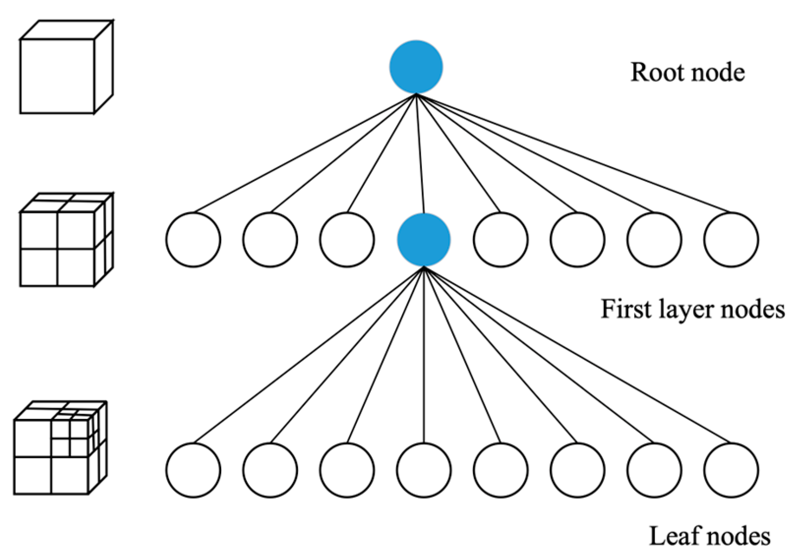
Octree is a commonly used data structure for space partitioning, the basic idea of octree is to divide the space into a series of cubes, and then recursively divide each cube again into eight smaller cubes until some termination condition is satisfied, as shown in
Figure 3. In a map application, the map can be divided into a series of cubes, each of which is called a “node”. Nodes can have three states: empty, leaf, and intermediate nodes. Empty nodes indicate that there is no map data in the region, leaf nodes indicate that there is map data in the region, and intermediate nodes indicate that the region is further divided into eight sub-nodes. By recursive division, the regions of the map can be represented as an octree. When querying the map data, each child node can be searched recursively starting from the root node until a leaf node containing the query point is found. In the octree, the node stores the chance of the square being occupied, using “0” and “1” to indicate the state, where a “0” means that the node is free, which means it can be passed, and a “1” means that the node is occupied, which means it cannot be passed.
The initial map obtained will be noisy, making some nodes affected by noise and unable to observe the state. The state of the nodes can be described by probability logarithmic (log-odds) methods. Suppose
represents the probability that a voxel block is occupied in the map, the probability logarithmic value of
is
, the value
can be computed by using Eq. (11):
The inverse transformation results in Eq. (12):
On an octree map, when a node is observed to be occupied, its corresponding
value increases, and vice versa, decreases. Thus
can be used to represent the magnitude of the probability that the node is occupied. Suppose a node be
n,
is the observation data of node
n at time
t, then the probability logarithmic value at time t+1 is shown in equation (13):
3. Semantic Visual SLAM System: Incorporating DeepLabV3+ Models, LK Optical Flow and Background Repair Techniques
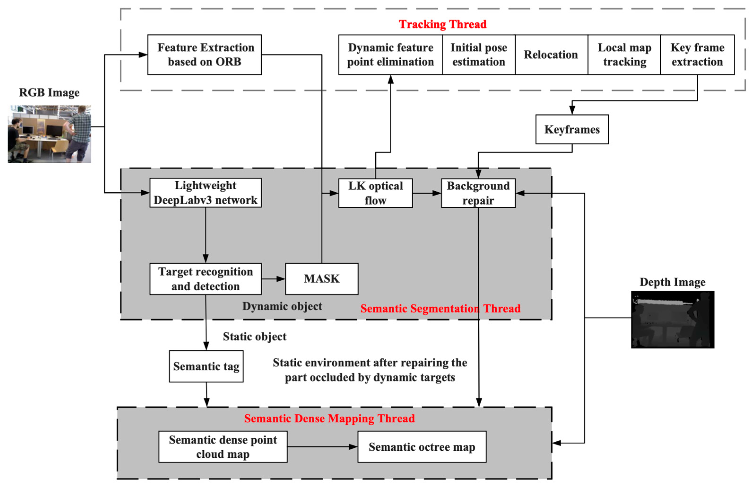
The semantic segmentation thread is added using ORB-SLAM2 as the base framework, which contains a semantic segmentation module, optical flow module, and background restoration module. The semantic segmentation module is used to obtain the prior semantic information in the environment and eliminate the prior dynamic feature points, the optical flow module is used to detect the non-prior dynamic feature points whose motion speed exceeds a certain threshold and after the processing of the two modules, the dynamic targets can be eliminated; the background restoration module is used to provide more accurate information in the case of re-localization. A semantic dense map-building thread is added. The semantic dense mapping thread is used to 3D reconstruct the map in the dynamic environment. The semantic segmentation results are used to construct the point cloud and octree map with semantic information, and the overall structural framework is shown in
Figure 4.
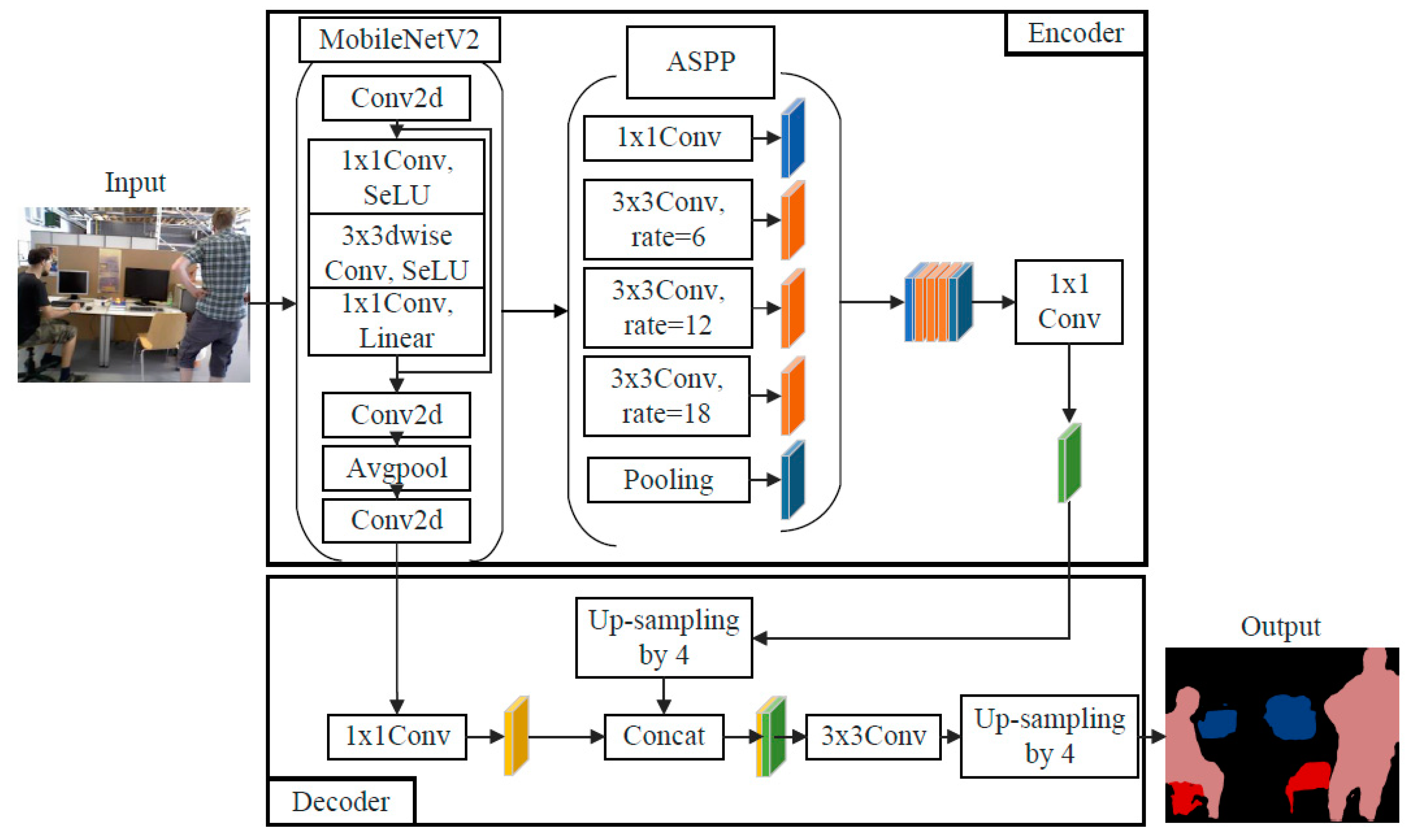
The RGB image is simultaneously passed into the tracking thread and semantic segmentation thread, in the tracking thread, the system extracts ORB feature points from the image and tracks them; in the semantic segmentation thread, firstly, the lightweight network MobileNetV2 [
29] is used as the backbone feature extraction network for the semantic segmentation network DeepLabv3+ [
30], and A lightweight semantic segmentation model is utilized to segment the mask of dynamic targets by segmenting all prior dynamic targets on a pixel-by-pixel basis, and the network structure is shown in
Figure 5. Next, the images after fusion of feature point extraction and semantic segmentation are fused to detect the ORB feature points covering the prior dynamic targets and remove them. Then, the dynamic target edge feature points and non-prior dynamic target points are further detected and rejected using the LK optical flow method. Finally, the static background occluded by the dynamic target is repaired using a time-weighted multi-frame fusion technique on the keyframes. Only the filtered relatively stable static feature points are used for feature matching and position calculation, thus ensuring the accuracy and robustness of this visual SLAM system in indoor dynamic environments.
The MobileNetV2 also adopts the depth separable convolution to reduce the number of model parameters, while using the inverse residual structure to increase the dimensionality of the convolution to improve the ability of the model to extract features, and then adopts the linear bottleneck structure to avoid the destruction of the low-dimensional spatial information by the nonlinear activation function to improve the performance of the network. As shown in
Table 1, MobileNetV2, as the backbone feature extraction network is compared with Xception, which is also trained using the widely used dataset PASCAL VOC2012, and the input image size is 512×512, the number of parameters is reduced by 89% and the number of operations is reduced by 68%. In comparison, the accuracy decreases by no more than 5%, and the time to process an image is 158ms, the inference speed is improved by 42.3%. The use of the lightweight network MobileNetV2 to replace the backbone network solves the problem of many network parameters and excessive dependence on hardware resources. It has a smaller network model and a faster processing speed to meet the real-time demand while ensuring accuracy.
To semantically segment the indoor environment, this study chooses the PASCAL VOC2012 dataset to pre-train the model, the dataset contains 20 different classes of objects as the training targets, possessing the dynamic targets: human, cat, and dog, and the static targets: cups, tables, chairs, and monitors. Considering the configuration of the experimental platform, the model training adopts the model-based migration learning method, loads the pre-training weights, and freezes the batch normalization layer of the backbone network MobileNetV2, with batch_size=2 when freezing the training, and batch_size=4 when unfreezing the training, which greatly saves the model training time, and effectively relieves the small amount of local data, small batch size, and insufficient computing power.
The LK optical flow is utilized to further detect and reject non-prior dynamic target points, and the threshold d in Eq. (7) takes the value of 5. If it is larger than this threshold, the feature point is determined to be a dynamic feature point, which will be deleted in the computation of the position, and will not participate in the feature matching and reprojection to compute the position.
The time-weighted multi-frame fusion technique is used to repair the static background occluded by the dynamic target, and the number of keyframes in Eq. (8) is taken to be 20. If the corresponding static images are not found in the previous keyframes, the image restoration algorithm will not be able to repair the static images efficiently, and these occluded portions will be retained.
The static object segmentation results and semantic labels from the semantic segmentation thread will enter the semantic dense map building thread, where the label mask with semantic information will be fused with the repaired static environment information to realize the point cloud map construction and the output will be a semantic map that does not contain dynamic targets and has semantic information, which will be converted into an octree map afterwards.
The specific running steps are as follows:
(1) Perform pixel point extraction using the feature points extracted from the keyframes after dynamic feature point exclusion.
(2) The extracted pixel coordinates are projected into the spatial coordinate system in combination with the depth information after background restoration, and the point clouds are stitched and fused.
(3) Remove isolated point clouds and depth-invalid point clouds, and perform map construction on the remaining point clouds.
(4) Combine semantic information with point cloud maps to generate semantic point cloud maps.
(5) Convert the semantic point cloud map into an octree map.
4. Experimental Results
4.1. Data Set Description
4.1.1. TUM RGB-D Dataset
Five sequences under the dynamic target category in the TUM RGB-D dataset were used, as shown in
Table 2. The TUM RGB-D dataset contains RGB and Depth data and true trajectory data provided by the Technical University of Munich. The dataset contains color images and depth images of the true motion trajectories along the Microsoft Kinect sensor. The data were recorded at a full frame rate of 30 Hz and a resolution of 640 × 480. A high-precision motion capture system obtained the true trajectories with eight 100 Hz high-speed tracking cameras. In the dataset, the dynamic target category is categorized into high-motion state (walking) and low-motion state (sitting), with the high-motion state indicating that the person is continuously walking in the scene; and the low-motion state indicating that the person is sitting still on a chair in the scene.
Meanwhile, the evaluation criteria of this dataset are used to verify the effectiveness of the proposed SLAM system, and they are Absolute Trajectory Error (ATE) and Relative Pose Error (RPE), respectively. The ATE directly calculates the difference between the estimated trajectory points and the real trajectory points and uses timestamps to correlate the estimated pose with the real pose, which can very intuitively reflect the algorithmic accuracy and the global consistency of the trajectory, and this criterion is suitable for evaluating the accuracy of the system. The RTE calculates the difference between the estimated trajectory points and the real trajectory points in the amount of trajectory changes in each same time interval, the relative position error contains relative translation error and relative rotation error, this criterion is suitable for estimating the drift of the system.
4.1.2. Self-Built Mobile Robotics Experimental Platform Data
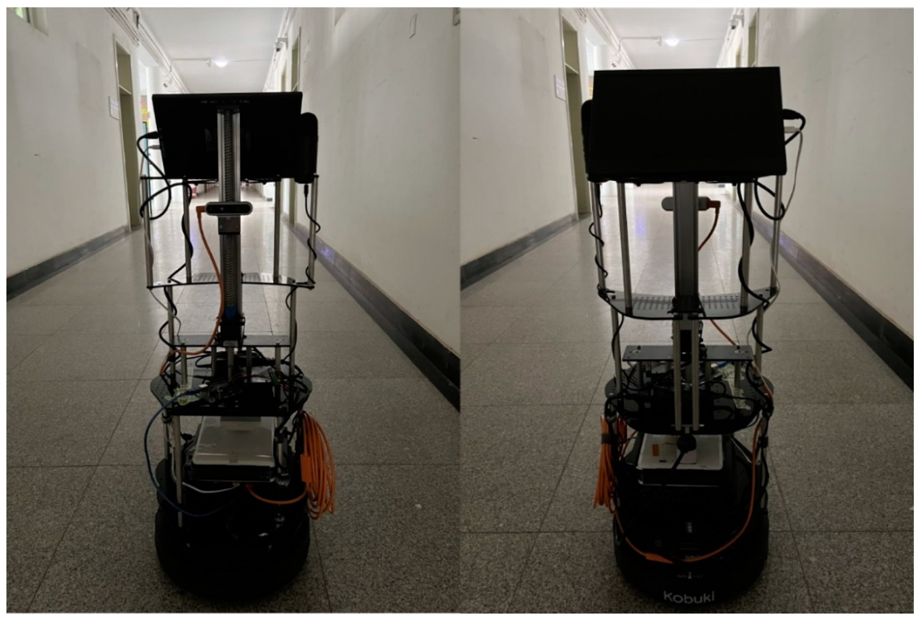
The Turtlebot2 robot is used to build the mobile robot experiment platform. The robot can better support the ROS system, using the Kobuki mobile chassis, with a maximum movement speed of 0.65 m/s and a maximum rotation speed of 180°/s, equipped with a mobile power supply, supporting 12V/1.5A and 12V/5A power supply modes. The experimental platform is also equipped with an Intel i5 industrial computer, an HP monitor, and a RealSense D435i depth camera; and a screw is installed to adjust the camera height, as shown in
Figure 6.
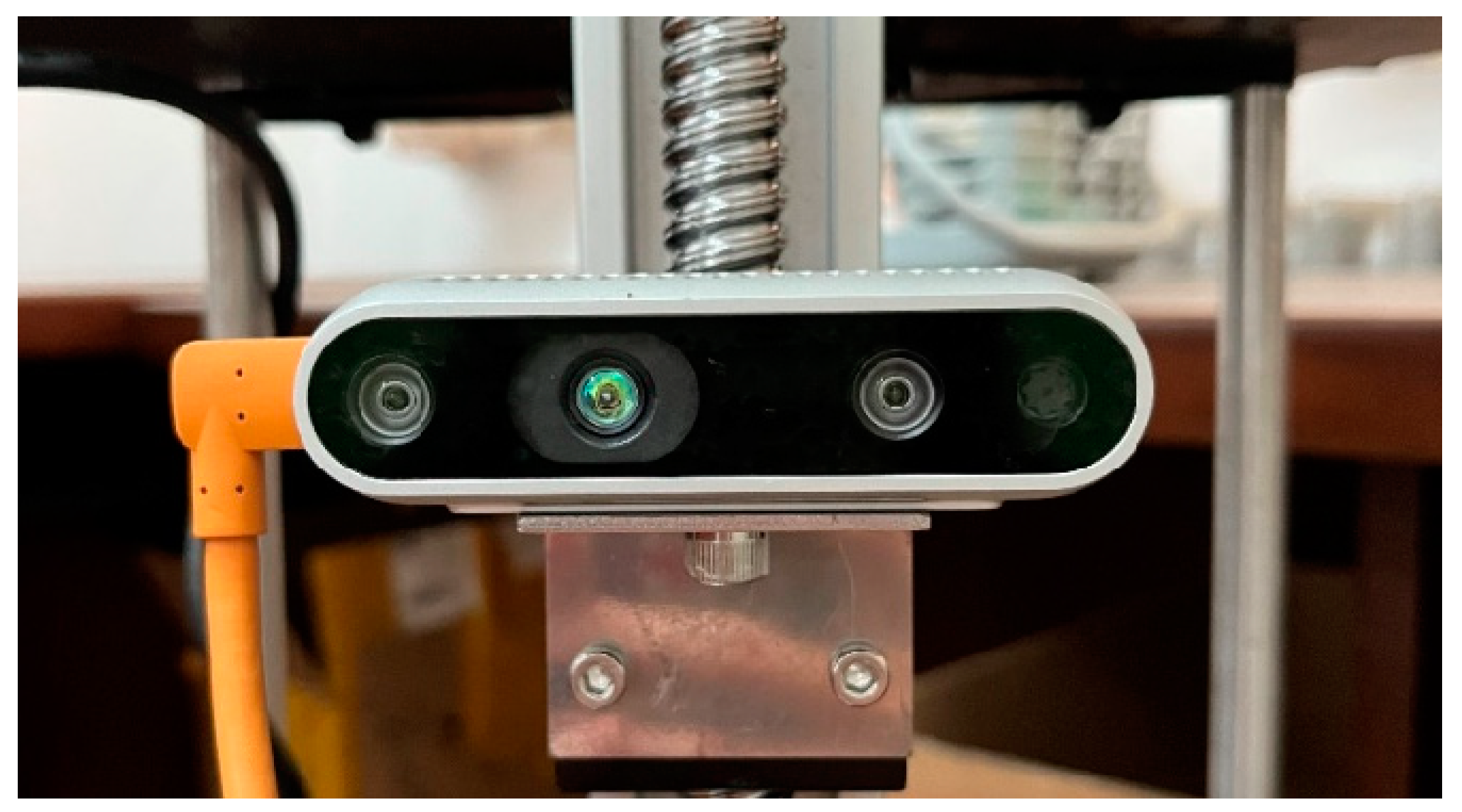
The Intel RealSense D435i depth camera is shown in
Figure 7 and the camera parameters are shown in
Table 3.
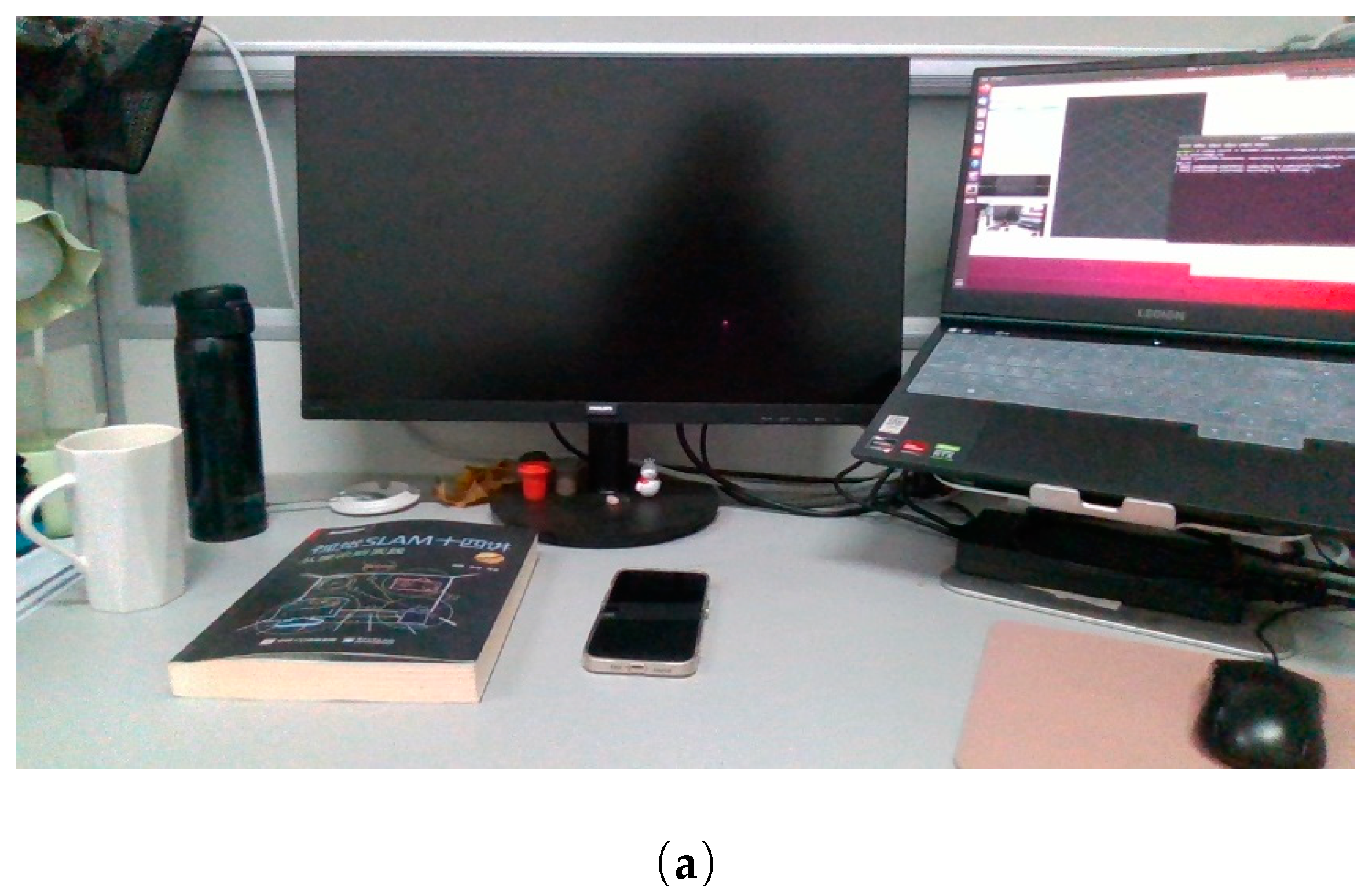
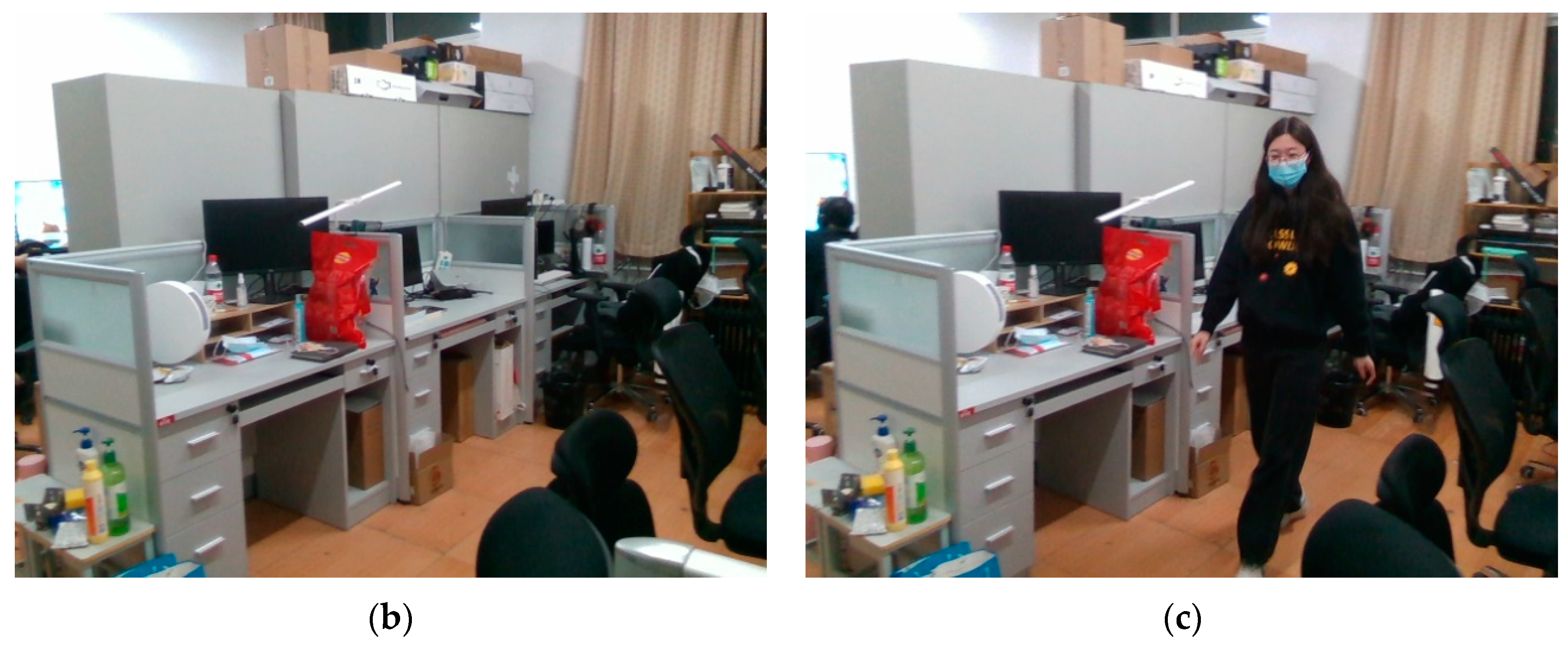
Based on the above mobile robot experimental platform, video data acquisition based on real scenes is carried out, and the office scene is selected for testing. In the office scene, two states are set, static and dynamic. In the dynamic state, there is a dynamic target “human”, which moves continuously; in the static scene, there are only static objects, including the desktop and the office environment. Part of the frame images are shown in
Figure 8.
4.2. Environment Configuration
The experimental platform is a PC with AMD Ryzen 7 5800H CPU, 16 GB of RAM, GeForce RTX 3060 GPU, and 6 GB of video memory, the system environment is Ubuntu 18.04, the programming language for the SLAM system is C++, and the programming language for the deep learning neural network is python, and the library function configuration and functions are shown in
Table 4.
4.3. Analysis of Experimental Results
4.3.1. Dynamic Target Elimination Experiments
(1) The TUM RGB-D data
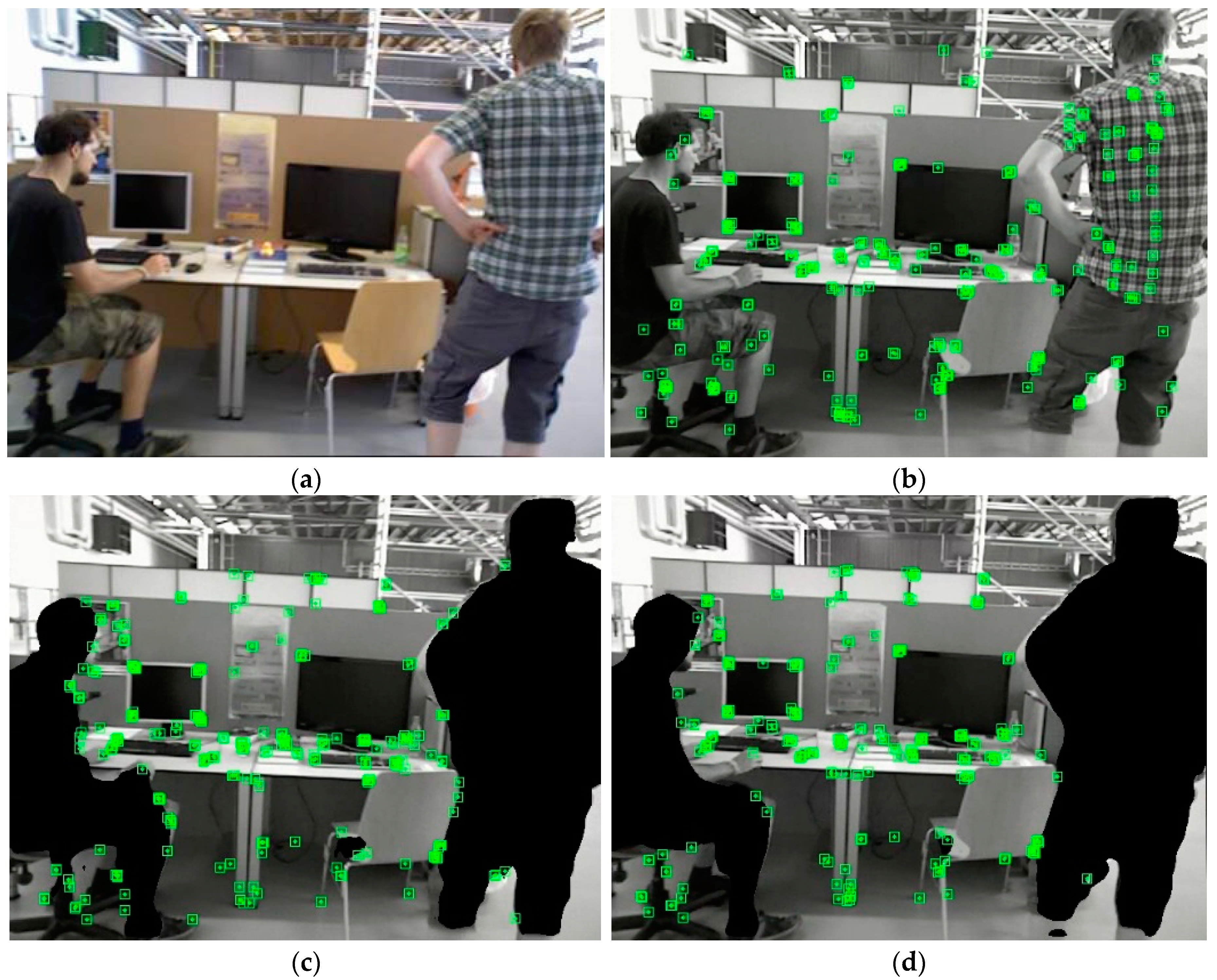
A single image in the TUM RGB-D dataset “walking_xyz” sequence was randomly selected for feature extraction in the ORB-SLAM2 system and the proposed system, and the results of processing this image are visualized as shown in
Figure 9.
As can be seen from the experimental results in
Figure 9(b), the ORB-SLAM2 system extracts the feature points within the dynamic target “human”, and as can be seen in
Figure 9(c), after adding the semantic segmentation network, the ORB-SLAM2 system covers the mask on the dynamic target “human”, and then no longer extracts the feature points within the target “human”, but still extracts the feature points at the edges of the human contour. As can be seen in
Figure 9(d), after adding the LK optical flow method to filter the feature points, the feature extraction result of this algorithm is significantly reduced compared with that of
Figure 9(c) in the dynamic target edge contour, which proves that the feature points whose motion speed exceeds the set threshold are deleted, and only the static feature points are left.
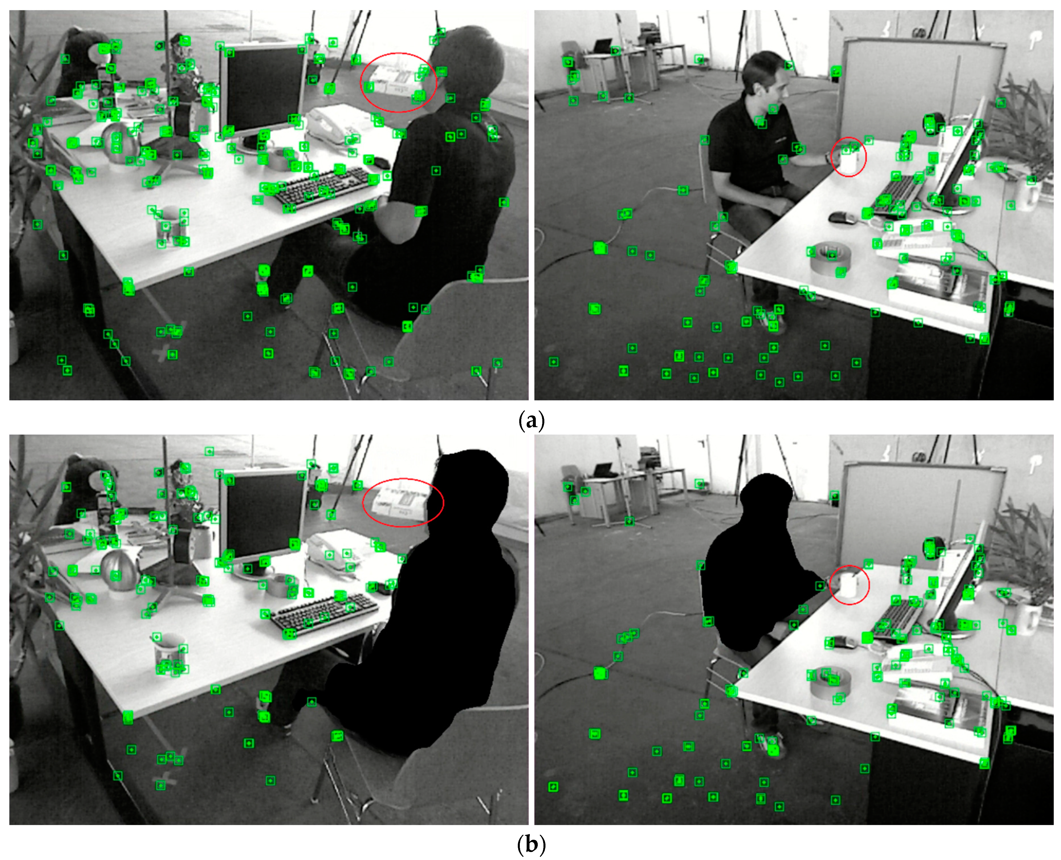
In real scenarios, in addition to the prior dynamic target “person”, there are also non-prior dynamic objects, such as books and cups moved by people in the “desk with person” sequence of the TUM RGB-D dataset, as shown in
Figure 10.
Figure 10(a) shows the result of extracting feature points by the ORB-SLAM2 system, and it can be learned that the ORB-SLAM2 system also extracts the features of the moving objects but does not do any processing. After filtering by LK optical flow method calculation in the improved algorithm, the feature points exceeding the threshold value are identified as dynamic feature points and are deleted, and the extraction results are shown in
Figure 10(b). The above experiments prove that the proposed improved SLAM system can effectively eliminate dynamic feature points, including the prior dynamic target “human” and the feature points on the non-prior dynamic target that moves with the human, to achieve the purpose of effectively eliminating dynamic targets.
(2) The experimental platform data
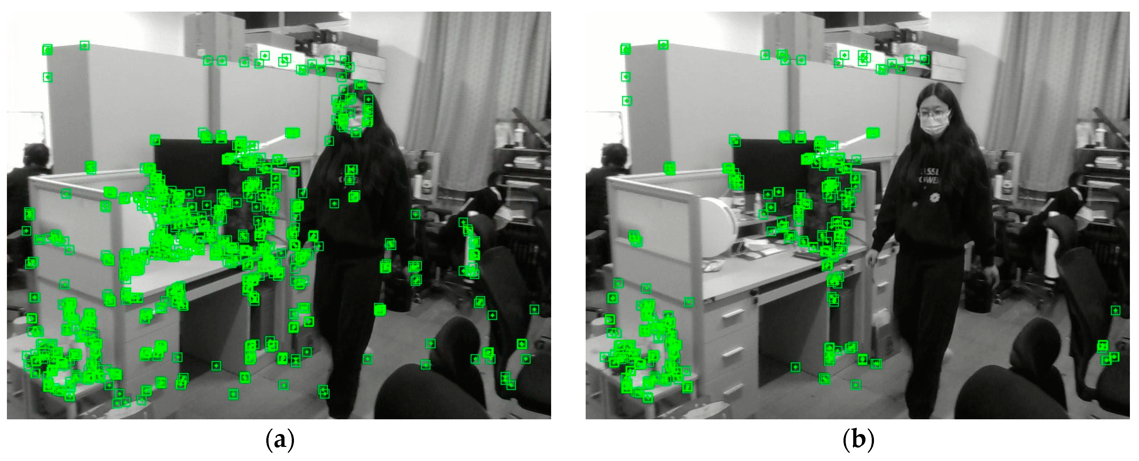
The dynamic office scene video captured by the mobile robot experiment platform was used to further verify the dynamic target feature point rejection effect. A frame is randomly selected for feature extraction using the ORB-SLAM2 algorithm and the proposed improved algorithm, respectively, and the extraction results are shown in
Figure 11.
Comparing
Figure 11 (a) and (b), the proposed improved algorithm can effectively filter out the moving parts of the dynamic targets in moving, such as the dynamic feature points on the limbs, and there is no similar phenomenon of clustering on dynamic targets as the ORB-SLAM2 algorithm. It can reflect the information of static images well. It proves that the proposed dynamic feature point rejection algorithm can be effectively applied to real-world scenarios.
4.3.2. Background Restoration Experiments
(1) The TUM RGB-D data
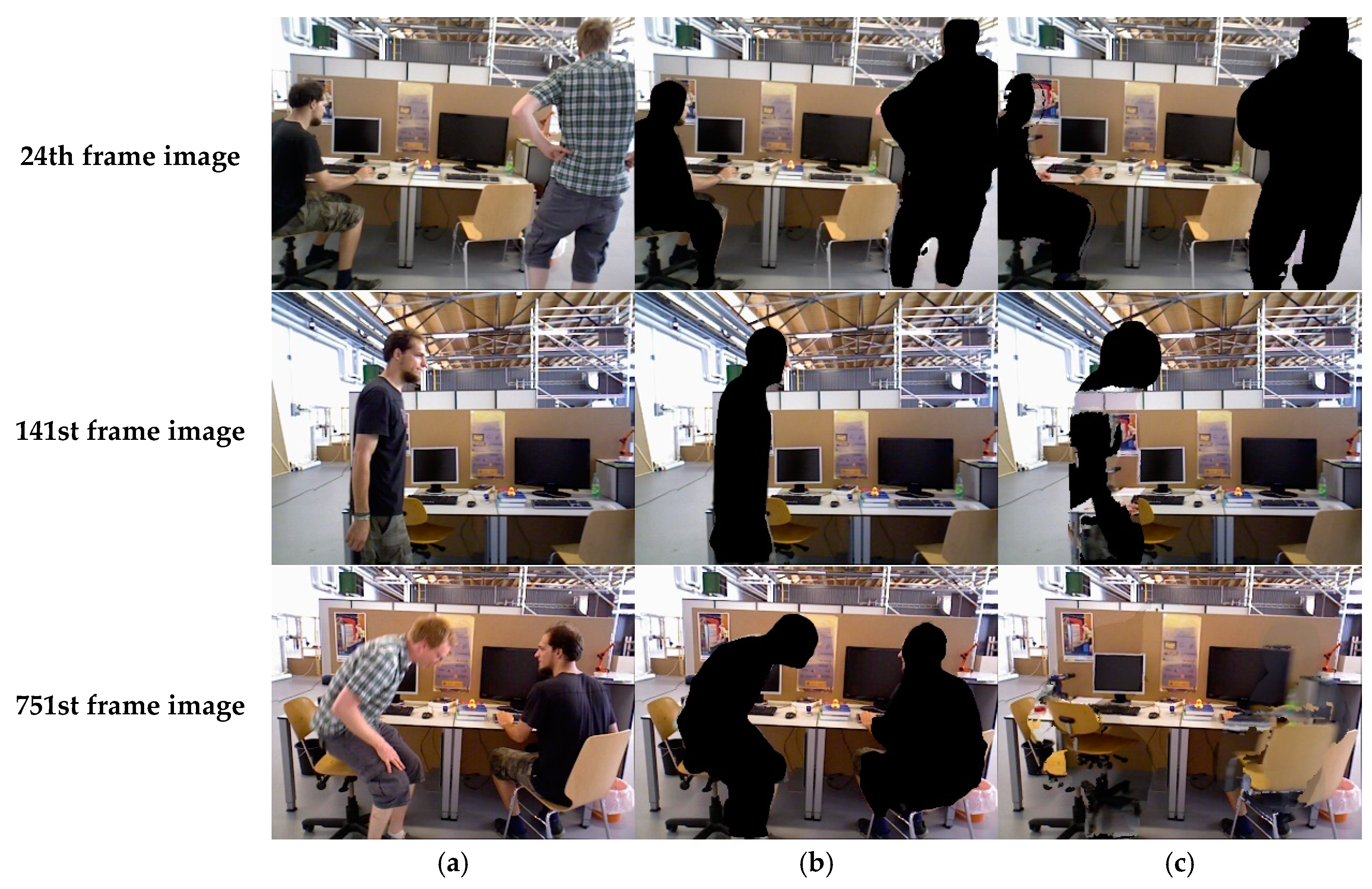
Three frames of images were randomly selected in the dataset “walking_xyz” sequence, and a comparison of the background restoration results is shown in
Figure 12.
In
Figure 12, (a) is the original image frame, (b) is the covering mask image after semantic segmentation, and (c) is the background repair image. As can be seen from frame 24, most of the background that was obscured by the character did not appear in the initial stage due to the limited background captured, so only a small portion of the background exposed by character movement could be repaired, such as the right silhouette of the left character. At the 141st frame, some effective backgrounds have been accumulated, and they can be partially repaired, but because some parts have been occluded before, e.g., the left portion of the computer desk is occluded for most of the time during the preliminary stage, these parts cannot be repaired for the time being. At frame 751, by looking at the entire dataset, it is found that all the scenes currently displayed on the set have been captured and can be repaired in their entirety, e.g., both monitors in the figure are displayed in their entirety. To summarize, initially, some areas cannot be completely repaired because the occluded parts up to this frame have not yet appeared completely in the field of view and do not have valid depth information. When the depth information is fully collected, most of the occluded background can be repaired.
(2) The experimental platform data
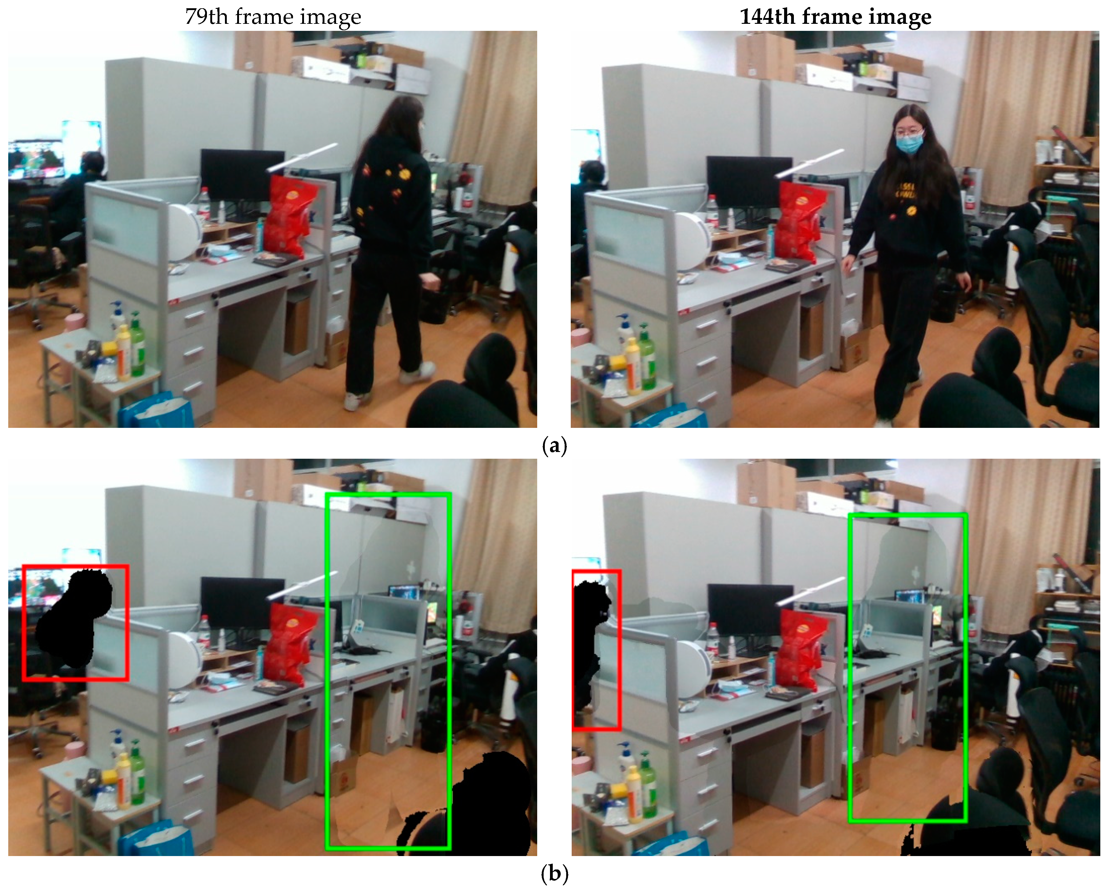
Further validation was performed using a video of a dynamic office scene captured by the mobile robot experiment platform. Two images were randomly selected, which contained the dynamic target person in a moving state continuously walking, and the dynamic target person in a relatively stationary state sitting on a chair. A comparison of the background restoration results is shown in
Figure 13.
In
Figure 13, (a) is the original image frame, and (b) is the background restoration. From the restoration results, most of the parts (in the green box) that have been occluded by the dynamic target character can be completely restored, which is due to the movement of the character, making the depth information acquisition complete. However, because some parts have been occluded before, such as the left part of the image (in the red box), where the dynamic target character is sitting on a chair, and the static background is occluded most of the time due to the presence of the mask, these parts cannot be repaired temporarily. To summarize, the background occluded by the dynamic target can be repaired efficiently.
4.3.3. Positioning Accuracy Experiments in an Indoor Dynamic Environment
(1) Positioning accuracy experiments
The ORB-SLAM2 system, the proposed improved algorithm, and other advanced SLAM algorithms applied to dynamic scenes were run on the above dataset respectively, and the camera position estimated by the improved algorithm was compared with the real position provided by the dataset. The test metrics include absolute trajectory error and relative position error. The statistics include Root Mean Square Error (RMSE), Mean of Error (Mean), Median of Error (Median), and Standard Deviation (STD). To calculate the difference, the timestamps were aligned in three scales: translation, rotation, and scale scaling, and the lift rate is calculated by Equation (14).
Where
is the lift rate,
is the operation result of the comparison algorithm,
is the operation result of the proposed improved algorithm.
Table 5,
Table 6 and
Table 7 show the comparisons of absolute trajectory error, relative position translation error, and relative position rotation error between the improved algorithm and ORB-SLAM2, respectively, and all the values are averaged over 5 samples.
As can be seen from
Table 5 to
Table 7, the proposed improved algorithm significantly performs better than the ORB-SLAM2 algorithm in high dynamic scenarios (walking). For example, the RMSE value of absolute trajectory error in the “walking_xyz” high-dynamic sequence is reduced by 97.81% and STD value by 97.74%, the RMSE value of relative position translation is reduced by 97.85% and the STD value by 98.14%, and the RMSE value of relative position rotation is reduced by 96.87% and STD value by 96.48%. The RMSE and the STD values of the absolute trajectory error are reduced by only 16.46% and 21.05%, the RMSE and the STD values of the relative position translation error are reduced by 16.52% and 22.22%, and the RMSE value of the relative position rotation is reduced by 10.41% and the STD value is reduced by 9.61% for the “siting_static” low-dynamics sequence. The RMSE value indicates the size of the error between the estimated value and the real value of the system, and the less the value indicates that the estimated trajectory is closer to the real value; the standard deviation reflects the degree of dispersion of the estimated value from the mean, and with a smaller value, it means that the system is more stable. Therefore, the comparison experiments show that the proposed improved algorithm has a higher localization accuracy and a smaller fluctuation in high dynamic environments, but since most of the targets in the low dynamic sequences are static and the dynamic targets are moving slowly, which has a smaller impact on the localization accuracy, the ORB-SLAM2 algorithm can have a good performance, and therefore, the enhancement of the proposed improved algorithm is not significant in the low dynamic sequences.
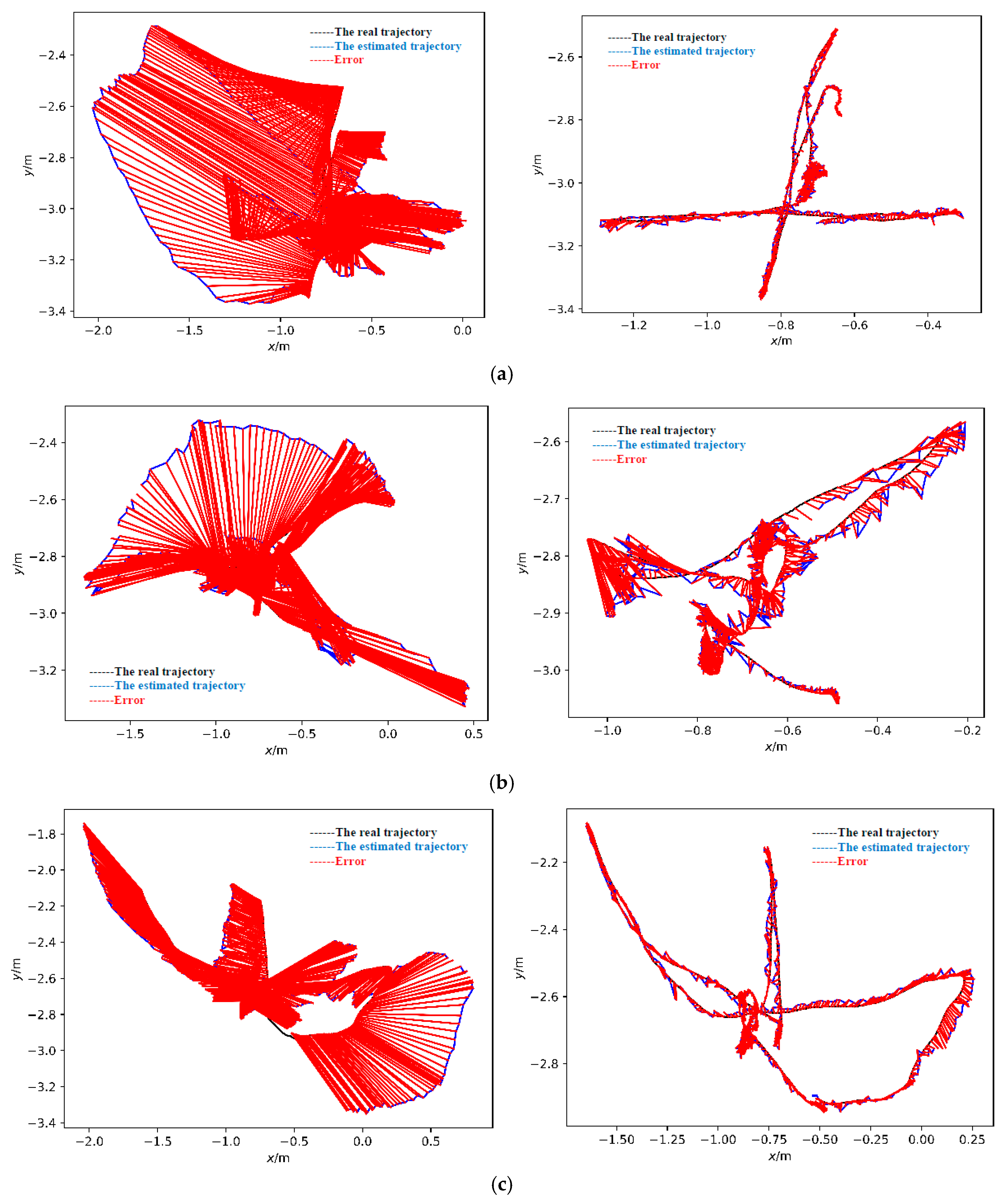
The left and right columns in
Figure 14 show the absolute trajectory errors of the ORB-SLAM2 algorithm and the proposed improved algorithm in the “walking_xyz”, “walking_rpy” and “walking_halfsphere” sequences, respectively. In the figure, the blue solid line is the estimated trajectory of the system, the black solid line is the real trajectory, the red solid line indicates the error, the horizontal coordinate is the horizontal position of the camera in space, the vertical coordinate is the vertical position of the camera in space. Compared with the real trajectory, the trajectory estimated by the ORB-SLAM2 algorithm has a large amount of drift, while the improved system is closer to the real trajectory.
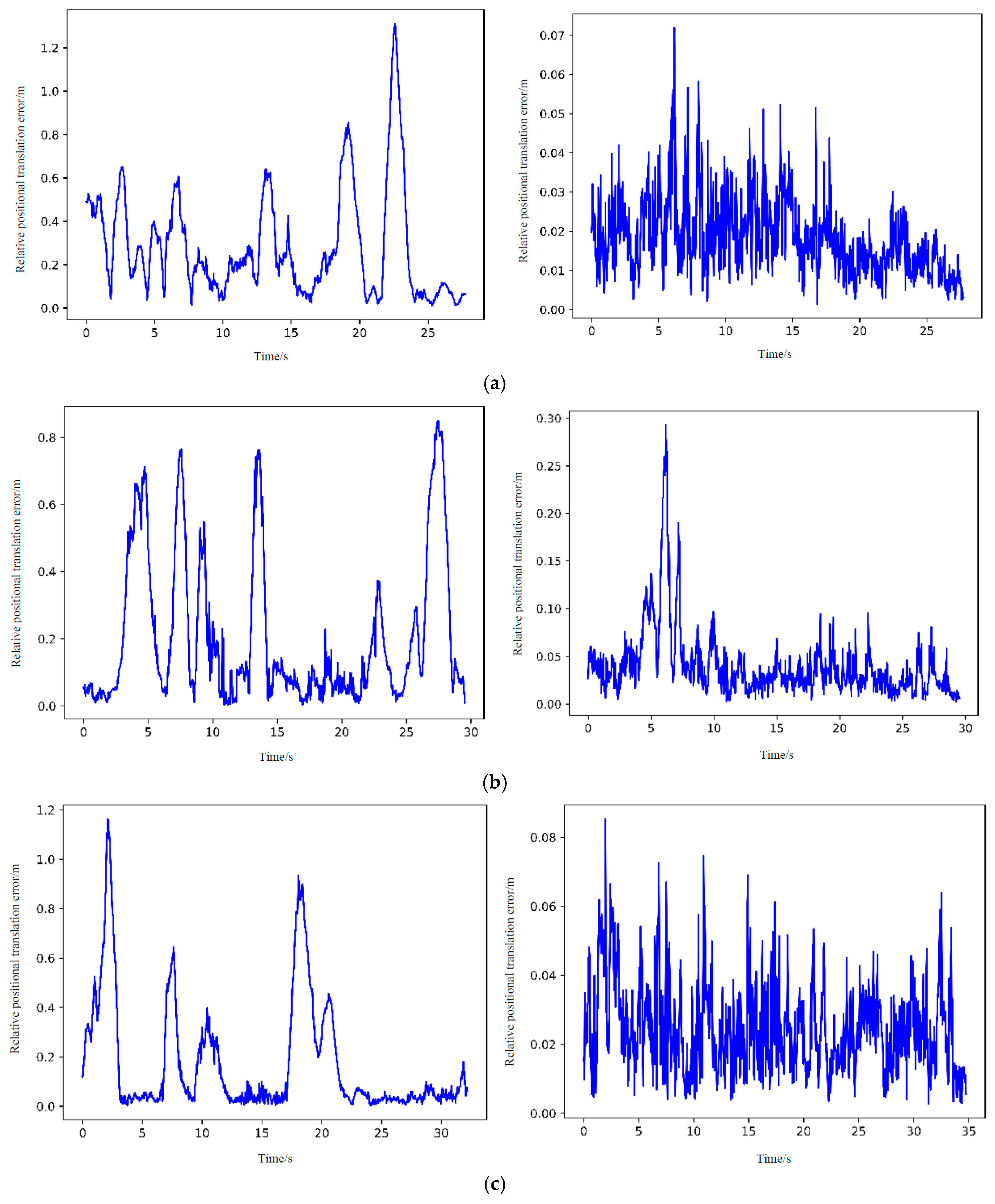
The left and right columns in
Figure 15 show the relative positional errors in the corresponding sequences for the ORB-SLAM2 algorithm and the proposed improved algorithm, respectively. The horizontal coordinate is the time, and the vertical coordinate is the relative positional translation error. It can be visualized that the error amplitude of the ORB-SLAM2 algorithm is very high and fluctuates greatly, compared with the proposed improved algorithm, which has smaller and more stable errors.
To further verify the effectiveness of the proposed improved algorithm, the proposed improved algorithm was compared with other advanced algorithms for dynamic environments. From
Table 8, it can be seen that the absolute trajectory RMSE values of all sequences of the proposed improved algorithm are smaller than those of DS-SLAM in the high-motion state scene (walking), and the error is far less than the original data provided by the Detect-SLAM paper; Compared with DynaSLAM, the positioning accuracy in “walking_halfsphere” and “walking_static” sequences is improved to some extent; Compared with the current excellent dynamic SLAM algorithm, the improved algorithm has the highest accuracy in “walking_halfsphere” sequence and “walking_static” scene. The improved SLAM system can achieve a high positioning accuracy in highly dynamic indoor environments and still has a relatively good performance in low-motion scenes, which proves that the system has good robustness.
(2) Ablation experiments
Ablation experiments were used to compare the errors of the proposed improved algorithm employing background restoration or not, and the results are shown in
Table 9. Where RPE (T) represents the relative positional translation error. This table shows that the overall cases using background repair are all smaller than the errors without background repair.
The ATE accuracy is only improved by 1.49% in the “sitting_static” sequence, while the ATE accuracy is improved by 98.52% in the “walking_halfsphere” sequence. By observing the output images of the improved DeepLabv3+ semantic segmentation, as well as the feature extraction and background restoration effects of the images during the system operation, it is found that in the “sitting_static” sequence, most of the image frames are occupied by the dynamic target “human”, so the algorithm is unable to extract enough static feature points for feature matching, and the background obscured by the person cannot be repaired because the person has been sitting on the chair for a long time without moving. In the “walking_halfsphere” sequence, the camera's trajectory is a hemispherical arc with a diameter of 1 m, and the character is constantly moving, which allows the camera to maximize the acquisition of static scenes from various angles and repair the background effectively. After the algorithm fails to track the feature points, the repaired background can provide more accurate feature matching during relocation. The use of background repair makes loop closing and mapping more realistic, resulting in the best accuracy improvement in the “walking_halfsphere” sequence.
(3) Analysis of system runtime
In addition to localization accuracy, the real-time performance of the system operation is also an important metric for evaluating SLAM systems. The system was tested for runtime on four high dynamic sequences and one low dynamic sequence. As shown in
Table 10, compared with the systems with the same level of positioning accuracy, the average tracking time per frame of the proposed improved algorithm is much smaller than that of DynaSLAM, and the detection speed is relatively faster due to the algorithm's lightweight processing of semantic segmentation network; although the processing speed is slightly slower than that of the ORB-SLAM2 on each frame of the image, the localization accuracy is greatly improved. While guaranteeing positioning accuracy, it meets the real-time demand and realizes the balance between accuracy and time consumption.
4.3.4. Mapping Experiments in an Indoor Dynamic Environment
4.3.4.1. Experiments of Dense Point Cloud Map Construction
(1) The TUM RGB-D data
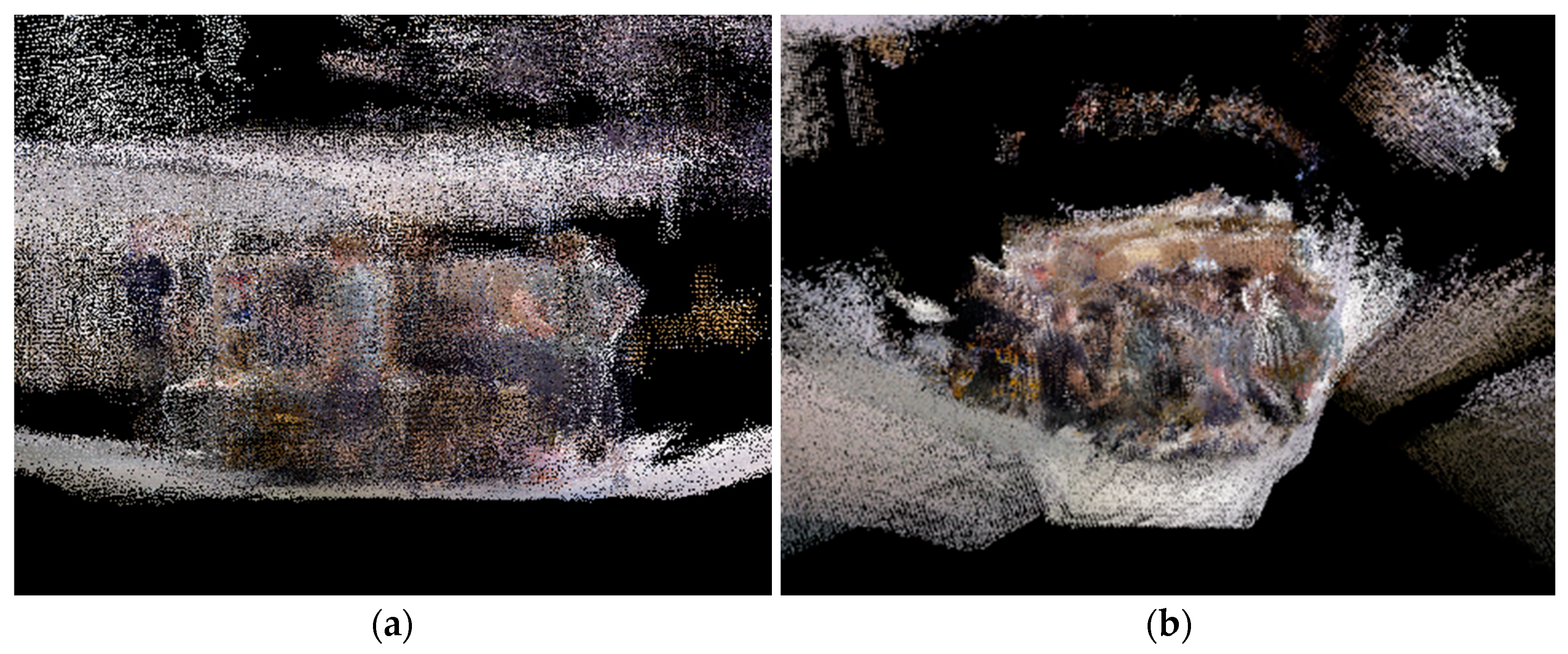
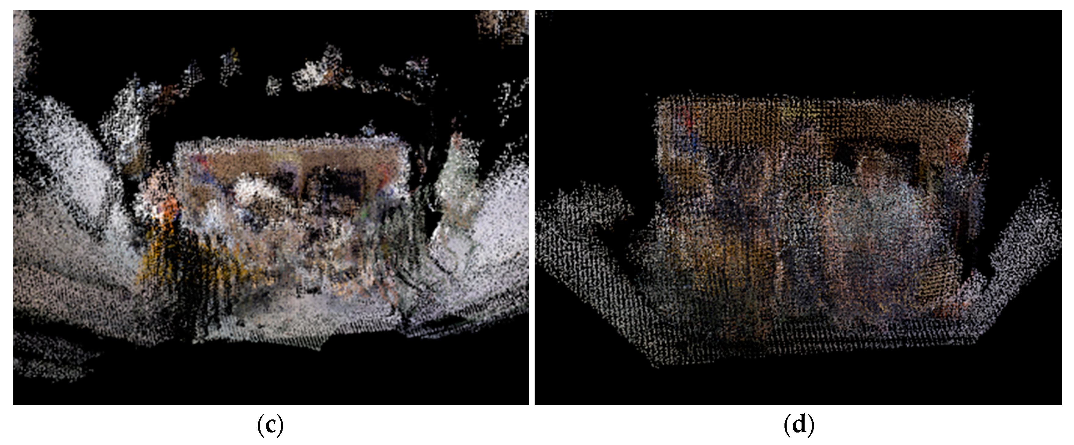
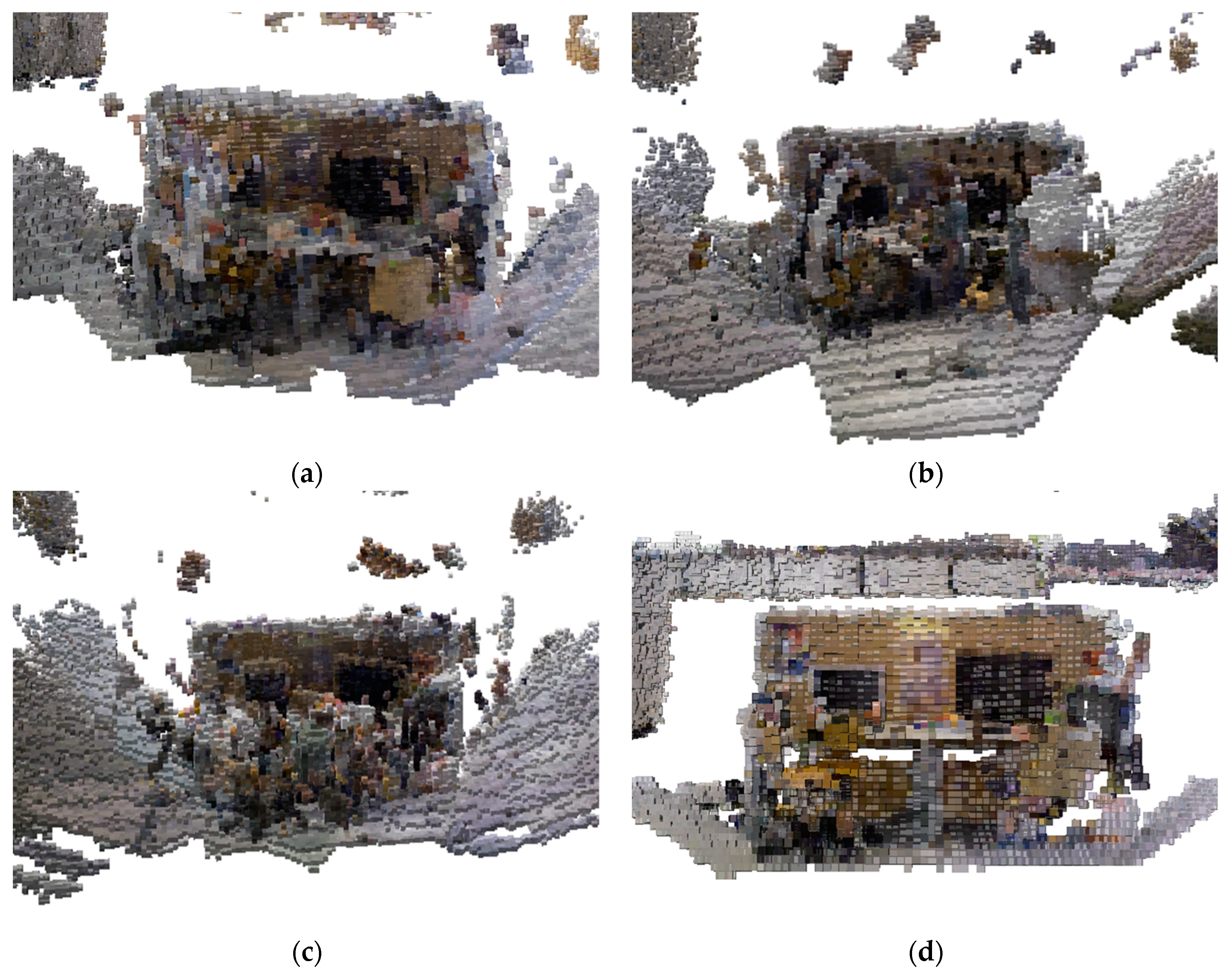
The dense point cloud map construction experiments were conducted using highly dynamic sequences in the TUM RGB-D dataset, namely “walking_xyz”, “walking_rpy”, “walking_halfspere” and “walking_static” sequences, which contain dynamic characters and the camera carries out the corresponding positional motion. For these 4 sequences, the ORB-SLAM2 algorithm and the proposed algorithm were used to build the maps respectively, and the results are shown in
Figure 16 and
Figure 17.
As can be seen in
Figure 16, the ORB-SLAM2 algorithm does not perform any processing for the dynamic target, which leads to many overlapping shadows as a result of image building. The main reason for this phenomenon is that the ORB-SLAM2 system records the point cloud of each frame, while in the above four sequences, the characters are always moving, and due to the change of the camera's position, the system detects and records the point cloud data at different positions, thus forming a series of overlapping shadows. In addition, in the high-dynamic sequence, the existence and movement of the dynamic target will affect the camera position estimation, leading to errors in the position estimation, so that the constructed maps cannot be well overlapped; at the same time, the point cloud splicing process will also generate errors, and the errors will be accumulated with the growth of time, resulting in the final constructed maps cannot be completely overlapped.
In addition to the map overlap being affected, these overlapping shadows will obscure the point cloud information of the static background, resulting in incomplete and erroneous map information, which will lead to inaccurate robot localization and path planning, or even choosing the wrong path, thus reducing the robot's navigation accuracy and efficiency.
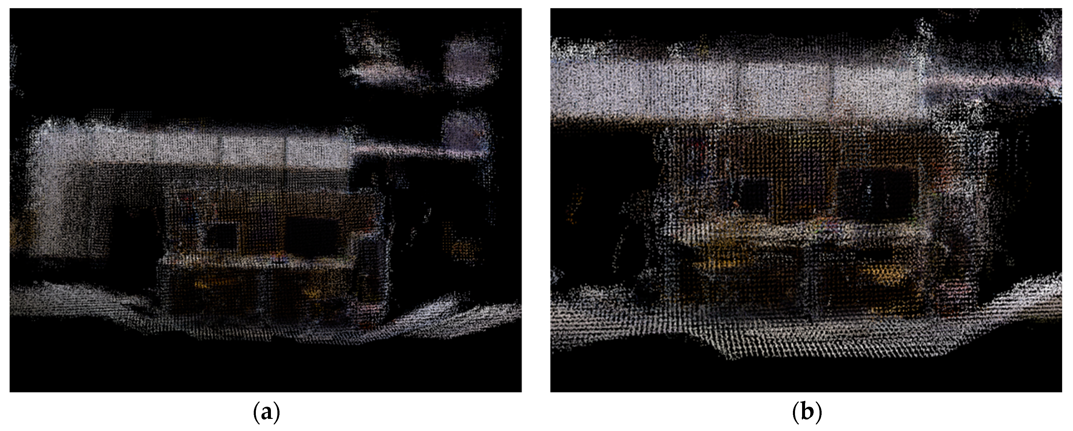
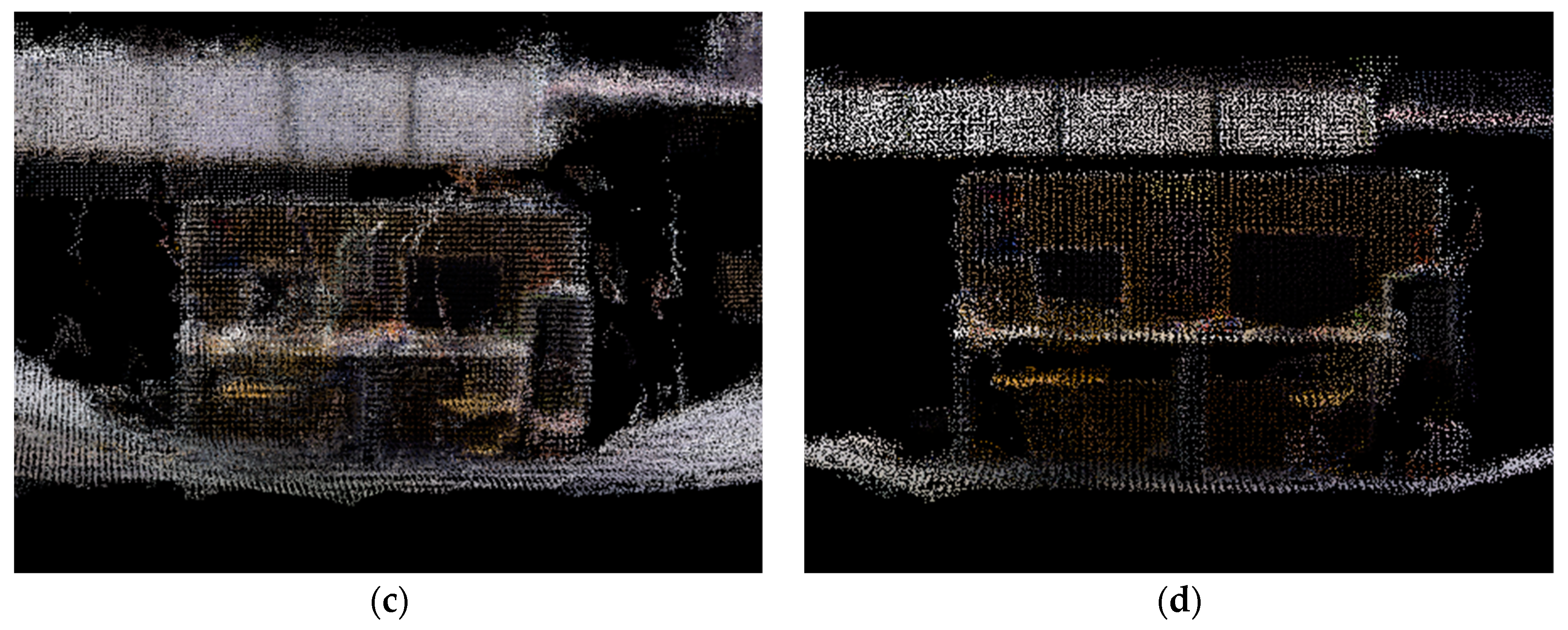
The proposed algorithm incorporates semantic segmentation threads into the ORB-SLAM2 system and utilized the semantic segmentation module and the optical flow module to eliminate moving and potential dynamic targets, to build dense static scene point cloud maps. As shown in
Figure 17, dynamic targets are culled and no longer obscure the static background, most of the static background point clouds are captured, and the ghosting problem is effectively improved. However, some noise can still be seen in the edge portion of the culled dynamic targets, this is because after semantic segmentation and optical flow detection, a small portion of the dynamic target feature points will be missed due to the accuracy of the segmentation and the setting of the threshold, and the missed portion will appear on the static background in the form of noise. Overall, the proposed algorithm that eliminates dynamic targets effectively improves the recognition of dense point cloud maps after reconstruction, the edge contours of objects in the scene are clearer, and the overlap between objects is lower. It eliminates the delamination due to the overlapping phenomenon, and the constructed maps overlap more, which enhances the readable performance of the maps.
(2) The experimental platform data
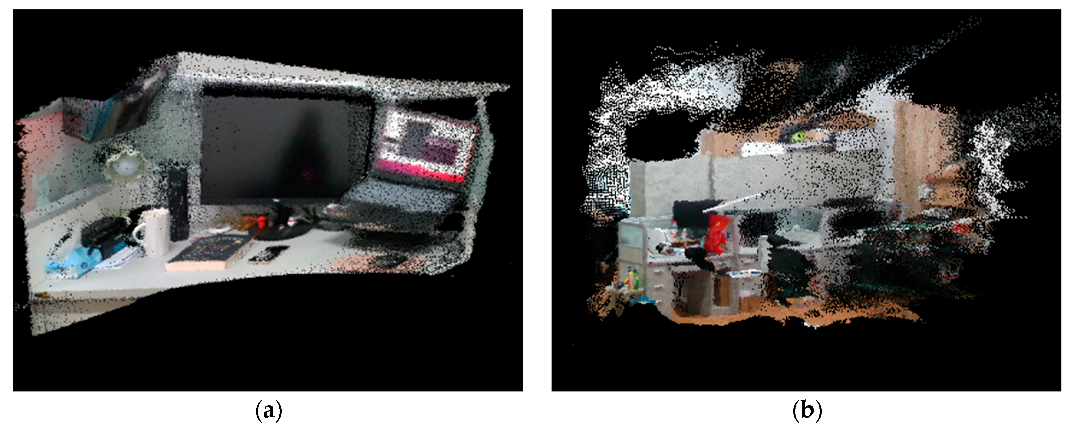
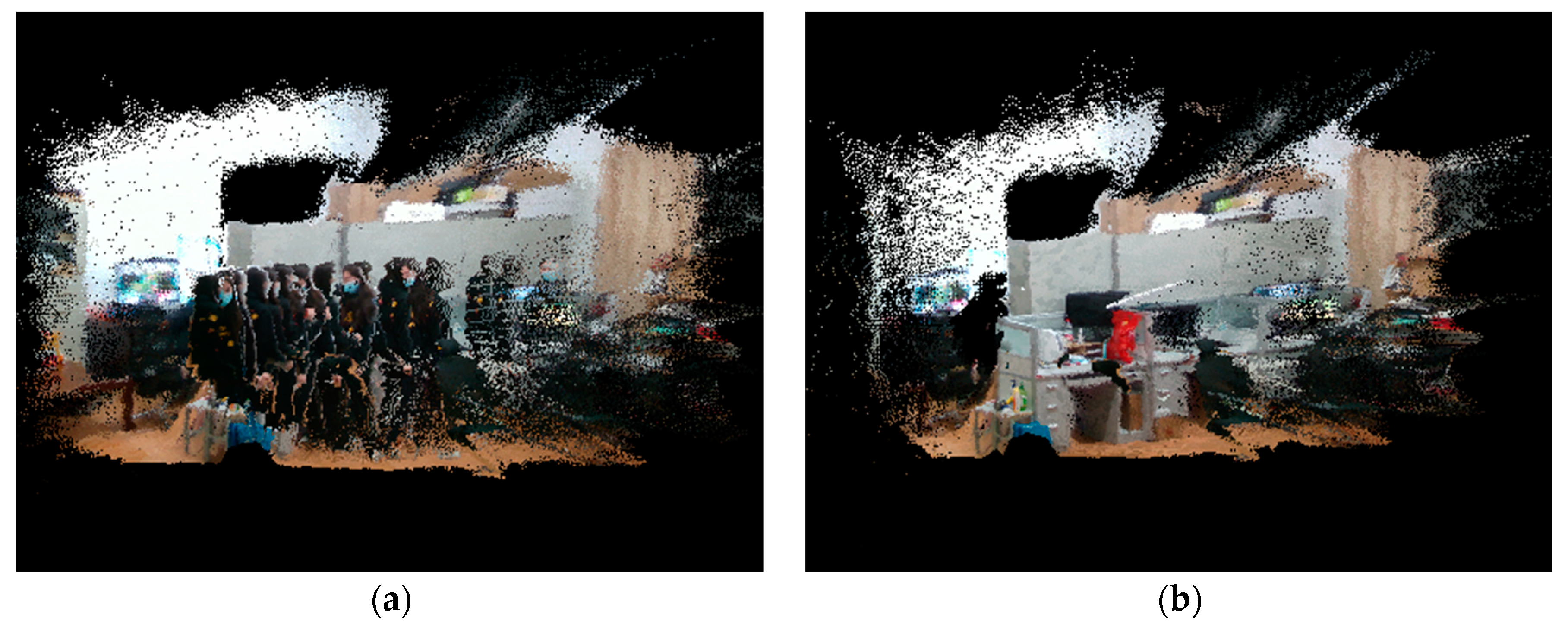
To verify the effectiveness of the proposed dense map construction algorithm in real environments, it was tested using office desktop and office dynamic and static environments. Comparison of map building using the proposed algorithm and ORB-SLAM2 algorithm, the results of point cloud map building are shown in
Figure 18 and
Figure 19.
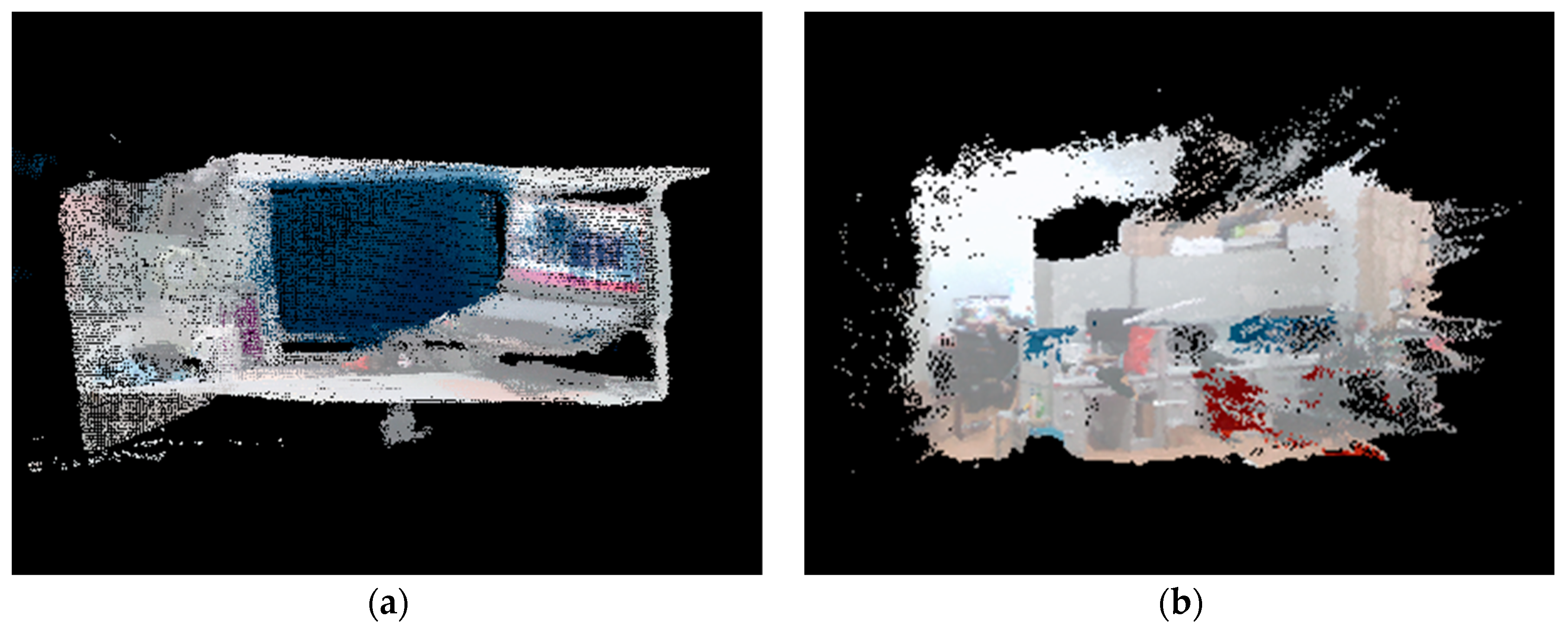
Figure 18 shows the static environment point cloud map constructed by the proposed algorithm, and the scene does not produce heavy shadows, layering, distortion, stacking, and misalignment, and the outlines of monitors, books, cups, cabinets, tables, etc. in the scene are clear, and the map is well readable.
Figure 19(a) shows the point cloud map of the dynamic environment constructed by the ORB-SLAM2 algorithm. The point cloud information in the scene is stacked and misaligned with each other, and there is a large amount of noise. Due to the existence of dynamic targets, the scene is full of heavy shadows left by dynamic targets, the effective information of the static scene is blocked tightly, and the readability of the map is extremely poor. In contrast, the proposed algorithm can better eliminate the dynamic targets and the ghosting phenomenon when constructing the point cloud map, thus generating clear static scene information and significantly improving the readability of the map, as shown in
Figure 19(b).
4.3.4.2. Experiments of Octree Map Construction
(1) The TUM RGB-D data
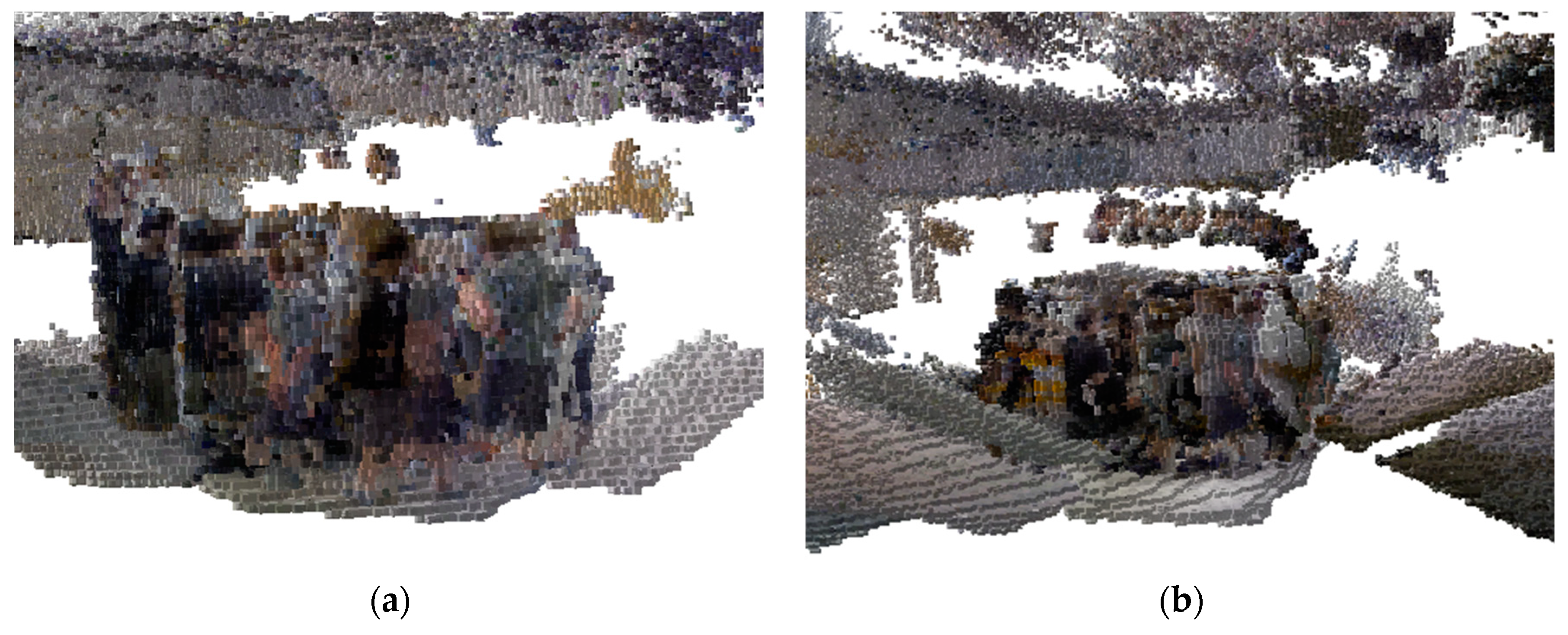
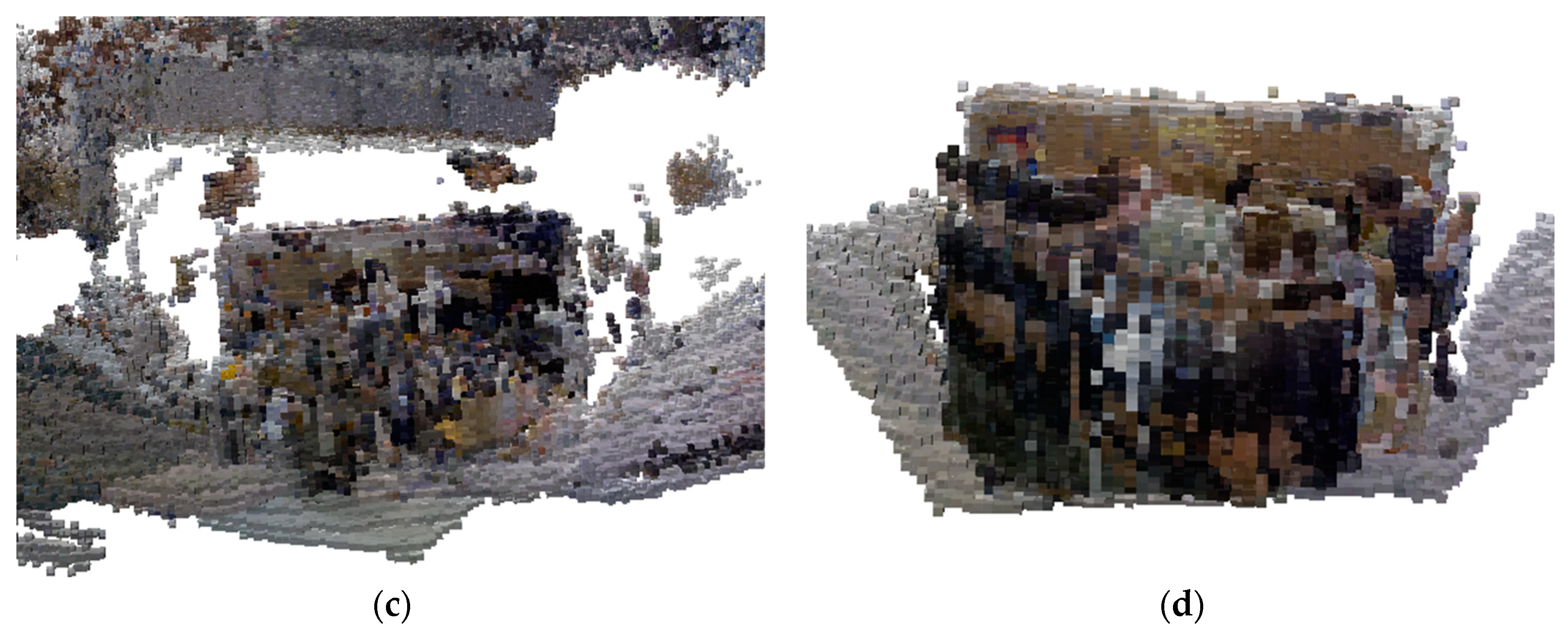
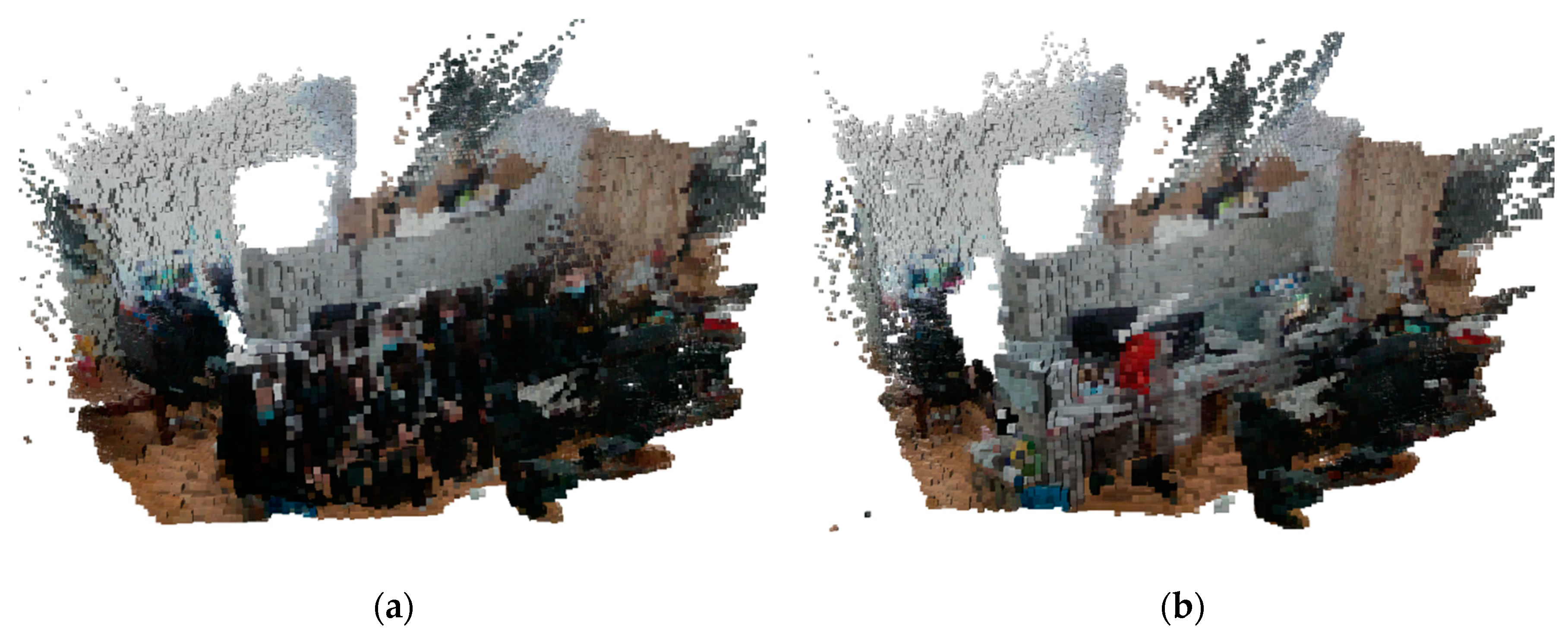
Since point cloud maps cannot provide specific location information and occupy a large amount of memory, octree maps were used to save maps for visual SLAM construction. The octree map construction experiments were conducted using highly dynamic sequences in the TUM RGB-D dataset, namely “walking_xyz”, “walking_rpy”, “walking_halfspere”, and “walking_static” sequences, which all contain dynamic characters. For these 4 sequences, the map construction effect was compared using the ORB-SLAM2 algorithm and the proposed algorithm, respectively, and the results are shown in
Figure 20 and
Figure 21.
Figure 20 shows the result of the octree map construction of the ORB-SLAM2 algorithm, in which there are many noise points and dynamic target “human” information, resulting in many overlapping shadows. Due to the presence of overlapping shadows of dynamic targets, the map of the whole scene appears to be very confusing, and due to the continuous changes in the position and movement state of dynamic targets, the overlapping shadows produced by them will also change, which makes the stability and reliability of the map greatly reduced. Moreover, the overlapping shadows occupy the whole scene, which means the information of the whole scene cannot be displayed completely, and even the outline of any object in the scene cannot be displayed clearly, which greatly reduces the readability of the map. In addition, these heavy shadows will also be recognized as obstacles, affecting the navigation accuracy of the subsequent mobile robot when it carries out navigation.
Figure 21 shows the result of octree map construction by the proposed algorithm, which utilizes the combination of semantic segmentation and optical flow method to eliminate dynamic feature points during feature extraction, thus effectively filtering out the dynamic targets in the scene. Compared with the ORB-SLAM2 algorithm, the octree map constructed by the proposed algorithm can better filter out the information of dynamic targets. In addition, the proposed algorithm also carries out background repair for the parts obscured by dynamic targets, so that the information in the scene can be clearly expressed in the map without the heavy shadows produced by moving people. The basic outline in the scene is very clear and the readability of the map is very high, which is very favorable for both robot navigation and map reuse.
(2) The experimental platform data
In
Figure 22, (a) shows the octree map constructed by the ORB-SLAM2 algorithm, and (b) shows the octree map constructed by the proposed algorithm. By comparing the axonometric view, the octree map constructed by the ORB-SLAM2 algorithm contains dynamic target information, which will appear as a series of heavy shadows, and the environmental information of the map itself cannot be seen at all, and does not have any effective information, which greatly reduces the map's readability and practicality. The octree map constructed by the proposed algorithm completely constructs the static background information in the scene, directly and effectively eliminates the dynamic target information, and displays the occupancy of the nodes, which can be used in the actual environment.
4.3.4.3. Experiments of Semantic Map Construction
(1) The TUM RGB-D data
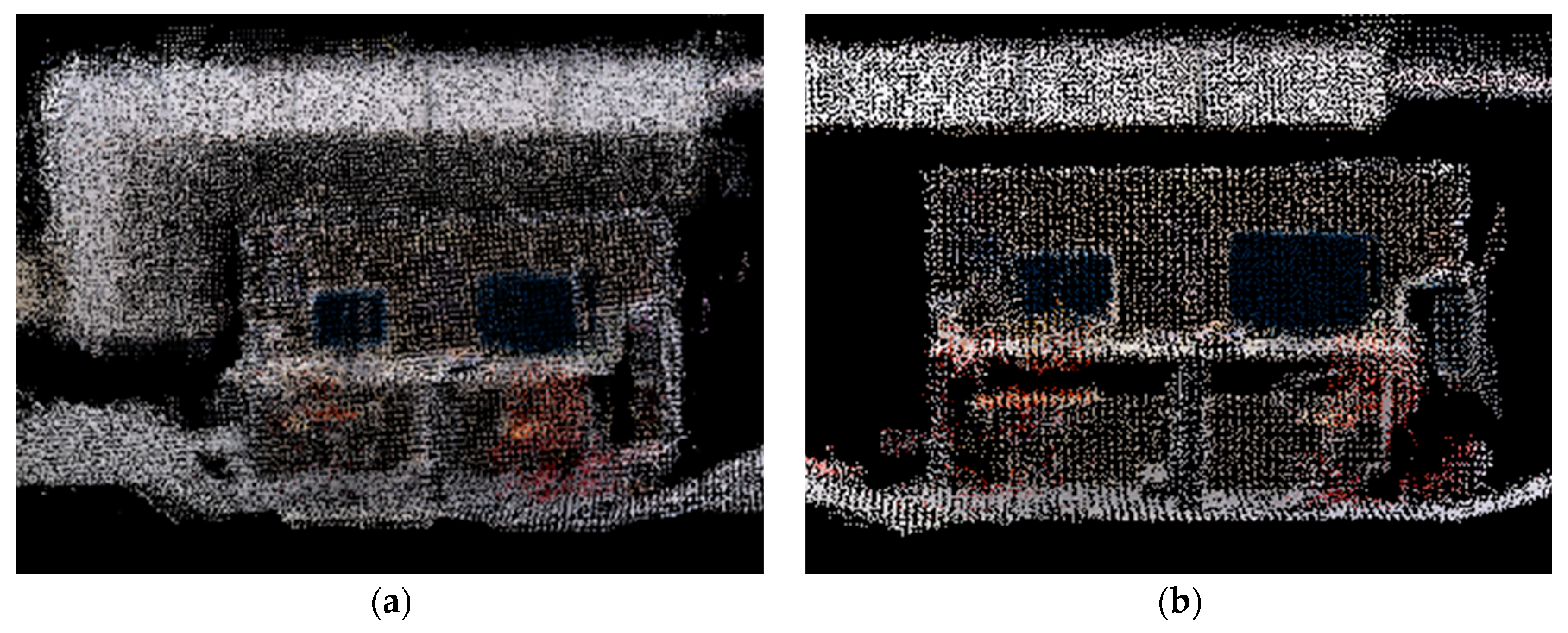
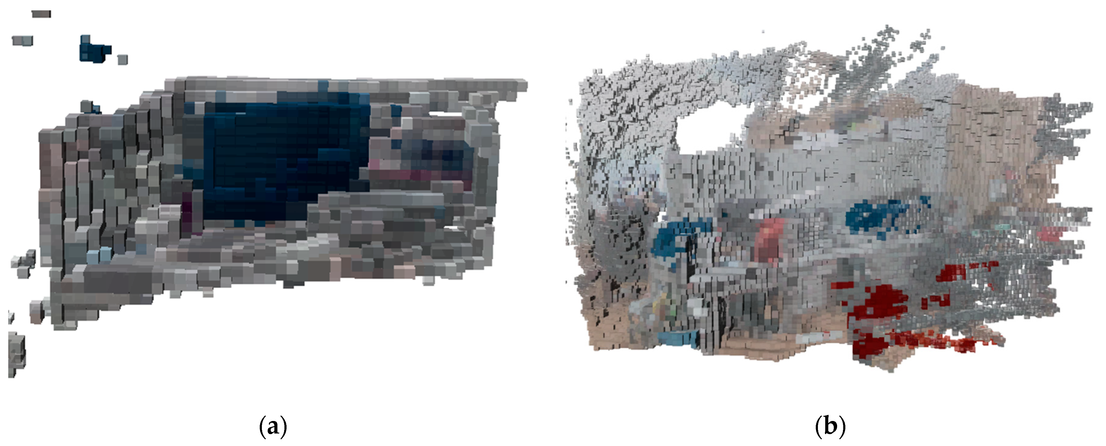
Semantic map construction experiments were conducted based on the successful establishment of dense point cloud maps and octree maps. Experiments were conducted using highly dynamic sequences in the TUM RGB-D dataset, namely “walking_xyz” and “walking_static” sequences, which both contain dynamic characters, and the camera carried out corresponding positional movements. For these two sequences, semantic mapping was performed using the proposed algorithm, and the results of the semantic point cloud map and semantic octree map are shown in
Figure 23 and
Figure 24.
In the semantic map construction experiments, the background recognition color was set to white to highlight the semantic information. The semantic information in
Figure 23 contains the monitor (recognition color is blue) and the chair (recognition color is red). From the figure, the proposed algorithm successfully removes dynamic targets and displays the semantic information of objects in static environments. The data points in the point cloud map are unambiguous, without obvious noise and interference, and without overlapping. It contains semantic information, which makes the data more useful and richer, and can provide more basis and decision support for various application scenarios.
As can be seen from
Figure 24, the proposed algorithm has filtered the dynamic targets. In the octree map environment, the static scene and semantic information can still be clearly represented without obvious flaws or artifacts, and it can provide detailed information about the occupancy of object targets for each location in the surrounding environment, which illustrates the validity and reliability of the proposed semantic map construction algorithm.
(2) The experimental platform data
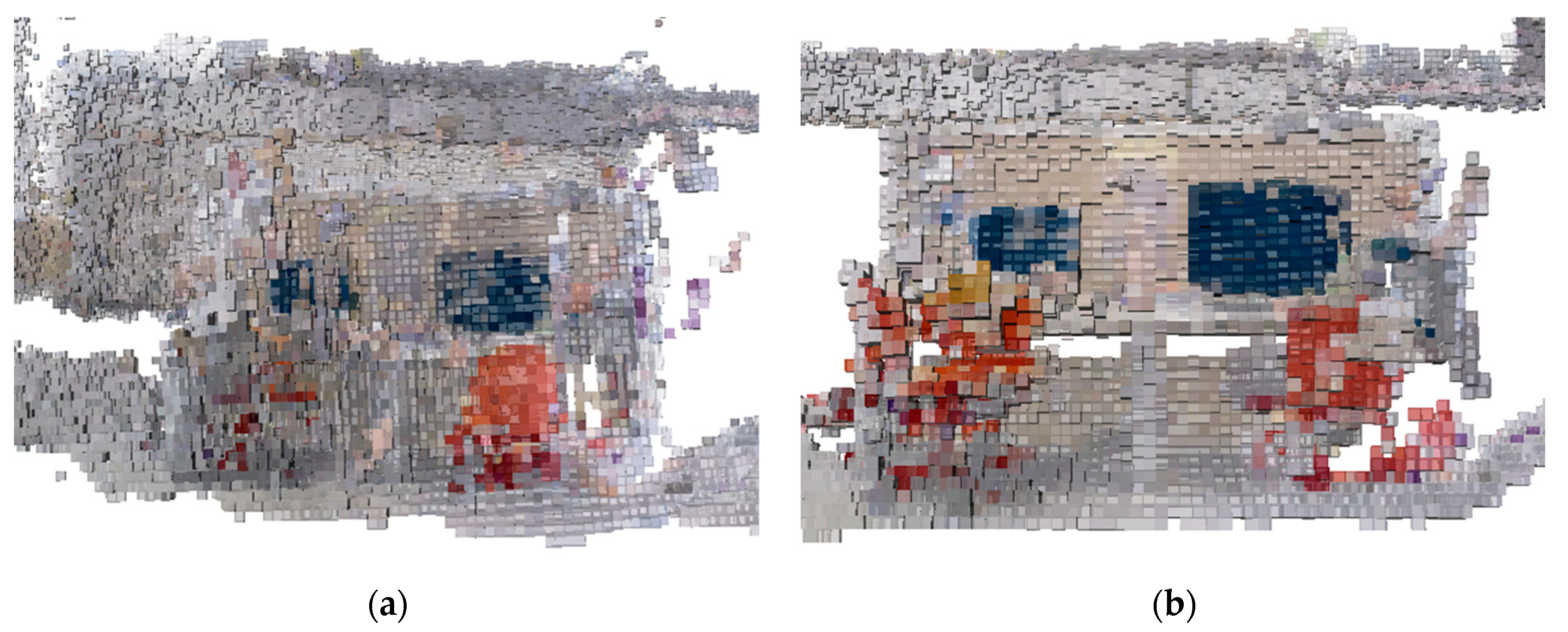
To verify the effectiveness of the semantic map construction algorithm, semantic maps were constructed in the dynamic and static scenes of the office environment mentioned above, and the results are shown in
Figure 25 and
Figure 26.
The overall construction of the desktop can be seen in
Figure 25(a) and is labeled with accurate semantic information. The main discriminators are the monitor (blue) and the chair (red).
Figure 25(b) shows the map construction results of the proposed algorithm after it has removed the interference of dynamic targets in the position estimation and improved the accuracy of position estimation. The result of Figure (b) indicates that the proposed algorithm is more effective in removing dynamic targets in constructing point cloud maps. The established point cloud map has high accuracy and can not only accurately express the spatial location information of the points in the environment, but also provide semantic information.
As shown in
Figure 26, octree maps containing semantic information are constructed using the proposed algorithm for real scenes. The constructed maps are relatively complete for both static and dynamic environments, containing all the important information in the environment, such as monitors and chairs, with accurate details and reasonable structure. In both maps, there are only a small number of missing or incorrect data points, and there are no invalid or duplicated areas. It can display various objects and structures in the environment, with better visualization effect, and can accurately represent the obstacles in the environment as well as the robot's movement path, which can meet the application requirements of robot localization, navigation, map building, or interaction.
4.3.4.4. Experiments of Map Memory Usage
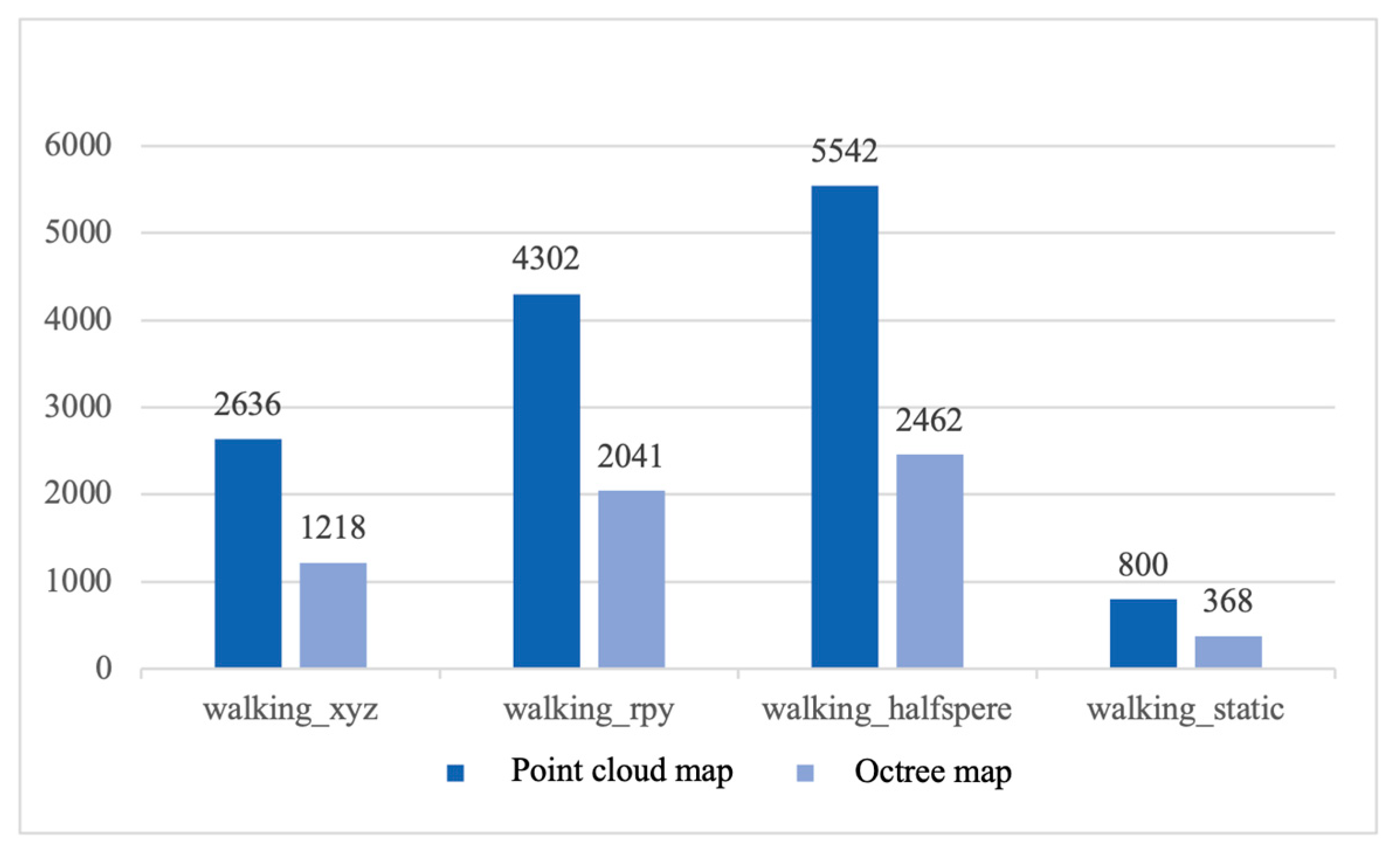
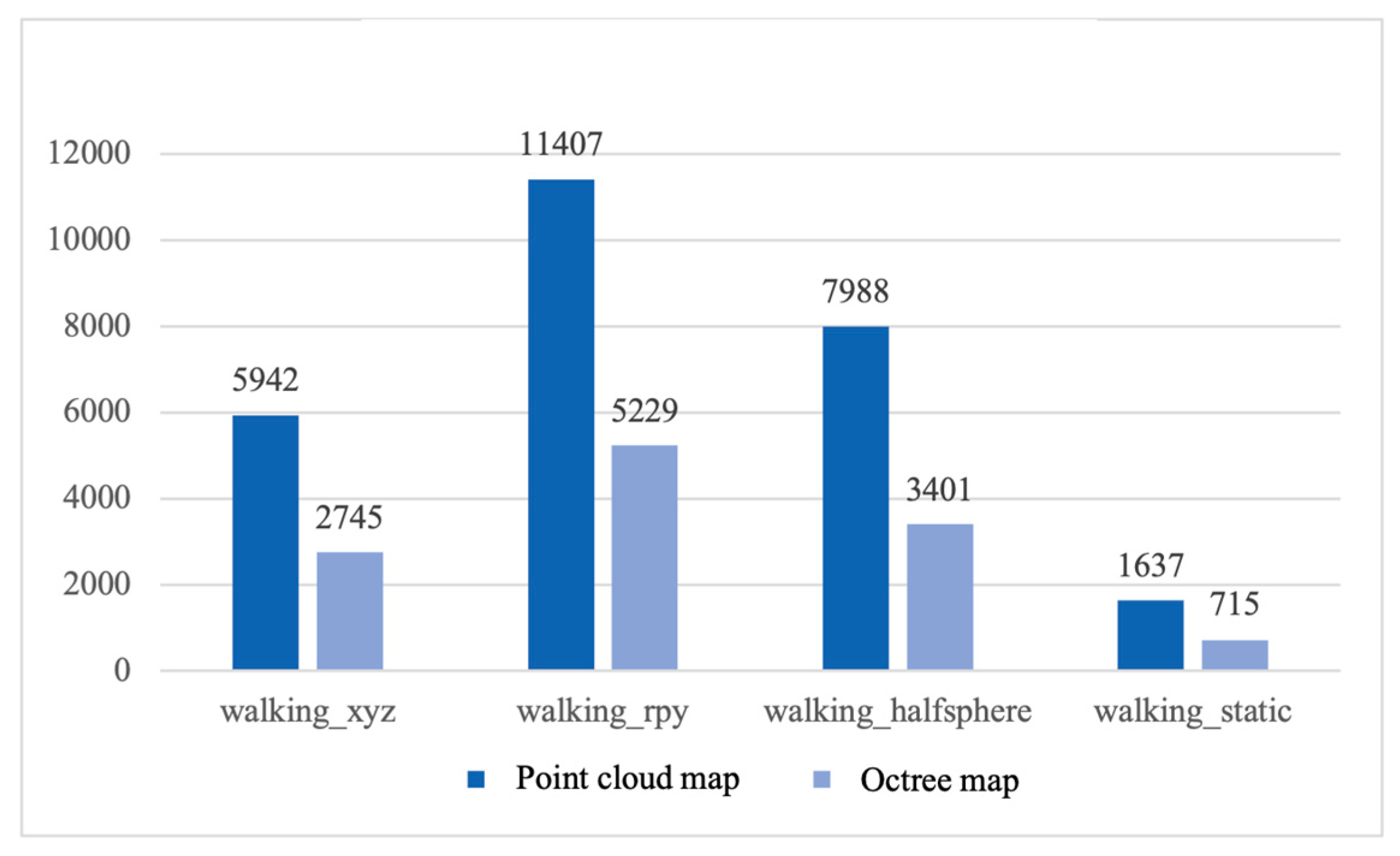
Comparing the storage memory usage of point cloud maps and octree maps, point cloud maps and octree maps were constructed using the proposed algorithms and the ORB-SLAM2 algorithm respectively for testing.
Figure 27 shows the memory occupation of the maps constructed by the proposed algorithm, and
Figure 28 shows the memory occupation of the maps constructed by the ORB-SLAM2 algorithm. From the bar chart, it can be intuitively seen that both the octree maps constructed by the proposed algorithm and the ORB-SLAM2 algorithm have a significant advantage in memory consumption compared to the point cloud maps. This is because octree maps can realize the fine representation of map information by constantly dividing the space, which indicates that octree maps can effectively save storage resources, and thus are very suitable for applications in robot navigation and path planning.
5. Conclusions and Future Work
The experimental results show that the proposed semantic visual SLAM algorithm for indoor dynamic environments, which incorporates the improved DeepLabV3+ model and LK optical flow, can solve the problem of visual SLAM being affected by dynamic objects during position estimation, improve the localization accuracy and position estimation accuracy, as well as can build semantic maps with semantic information, and solve the problem of the overlapping phenomenon caused by dynamic objects in the mapping construction. The specific conclusions are as follows:
(1) An algorithm for visual SLAM that combines semantic segmentation, optical flow, and background repair is proposed. First, a lightweight network MobileNetV2 is used to replace the backbone feature extraction network Xception for semantic segmentation, resulting in an 89% reduction in the amount of network parameters, a 68% reduction in the number of operations, and a 42.3% improvement in inference speed. Second, the improved DeepLabV3+ semantic segmentation network is combined with LK optical flow. The Semantic segmentation can segment the specific contour of prior dynamic targets and eliminate the prior dynamic feature points, and the optical flow can detect the non-prior dynamic feature points whose moving speed exceeds a certain threshold, and the combination of the two can effectively eliminate the dynamic feature points and reduce the impact of dynamic targets on the system localization accuracy and the position estimation accuracy. Finally, after the dynamic targets are eliminated, the static environment information is repaired by time-weighted multi-frame fusion technology, which provides relatively complete scene information for system repositioning and map construction. The algorithm can effectively reject the prior and non-prior dynamic targets and effectively repair and restore the static background obscured by the dynamic targets in the highly dynamic scene.
(2) An algorithm for constructing indoor maps based on semantic information for dynamic environments is proposed. First, the improved semantic segmentation network is used to obtain semantic labels of static objects; then, the static background information after removing the dynamic targets and restoring the background is fused to build a semantic dense point cloud map; finally, the octree spatial segmentation data structure is used to convert the semantic dense point cloud map into a semantic octree map, which saves the storage space and provides a map basis for robot navigation and path planning.
(3) In the positioning accuracy experiments, compared with the ORB-SLAM2 algorithm, this proposed algorithm has a more accurate position estimation, a higher positioning accuracy, and a better robustness in high dynamic environments; in the system running time experiments, by comparing the real-time performance of other advanced algorithms. The above experiments prove that the proposed algorithm ensures the system's running speed while effectively improving positioning accuracy.
(4) In the map construction experiments, the proposed algorithm compared to the ORB-SLAM2 algorithm constructs maps with higher accuracy and clarity. It not only reduces the effect of dynamic targets and eliminates the overlapping shadow phenomenon, but also contains object semantic information. Meanwhile, the constructed dense point cloud map can be converted into an octree map. This experiment proves that the proposed algorithm can build high-quality and information-rich maps. In the map memory occupancy experiments, comparing the size of memory occupied by two kinds of maps proves that the use of the octree map format effectively reduces the memory occupied space.
Based on the above conclusions, the authors believe that the proposed algorithmic model can be applied to the localization of AGV mobile robots and the construction of semantic maps in the surrounding dynamic environment, which can provide a basis for the navigation and path planning of AGV mobile robots. Given that the current work does not consider depth information, our next work will explore depth map semantic segmentation by combining depth maps with color images for semantic segmentation. Using depth information to more accurately judge the position, size, and shape of objects in the scene, helps to improve the accuracy of semantic segmentation of color images and further improves the accuracy of AGV positioning and map construction. Meanwhile, the process of point cloud generation is improved by optimizing the process of point cloud data acquisition, filtering, and alignment to reduce the generation of noise points as much as possible, improve the accuracy and robustness of the maps, and solve the problem that there are still an individual or a slight number of noise points in the semantic maps.
Author Contributions
The manuscript was heavily influenced by all the contributors. Y.L. made important contributions to the study design, algorithm implementation, data management, chart production, and manuscript writing. Y.G. and Y.W. provided project support for the study and made important contributions to the idea of the study, as well as the writing and review of the manuscript. L.L. and Q.A. made important contributions to the literature search, data acquisition, and data analysis. All authors have read and agreed to the published version of the manuscript.
Funding
This research was funded by “Open project of Key Laboratory of modern measurement and control technology of Ministry of Education, Grant No. KF20221123205”, “the Young Backbone Teachers Support Plan of Beijing Information Science & Technology University, Grant No. YBT 202405”, and “General Science and Technology Program of Beijing Municipal Education Commission Grant No. KM202011232011”.
Data Availability Statement
Conflicts of Interest
The authors declare no conflicts of interest.
References
- GU Zhaopeng, LIU Hong. A survey of monocular simultaneous localization and mapping[J]. CAAI Transactions on Intelligent Systems,2015,10(4):499-507. [CrossRef]
- Davison A J , Reid I D , Molton N D ,et al.MonoSLAM: real-time single camera SLAM[J].IEEE Transactions on Pattern Analysis and Machine Intelligence, 2007, 29(6):1052-1067. [CrossRef]
- Klein G , Murray D .Parallel Tracking and Mapping for Small AR Workspaces[C]. 2007 6th IEEE and ACM International Symposium on Mixed and Augmented Reality, 2007:225-234. [CrossRef]
- Newcombe R A, Lovegrove S J, Davison A J. DTAM: Dense tracking and mapping in real-time[C]. 2011 International Conference on Computer Vision, 2011:2320-2327. [CrossRef]
- Forster C, Pizzoli M, Scaramuzza D. SVO: Fast semi-direct monocular visual odometry[C]. 2014 IEEE International Conference on Robotics and Automation (ICRA), 2014:15-22. [CrossRef]
- Engel J, Schöps T, Cremers D. Large-Scale Direct Monocular SLAM[C]. Computer Vision - ECCV 2014, 2014:834-849.
- Engel J, Koltun V, Cremers D. Direct sparse odometry[J]. IEEE Transactions on Pattern Analysis and Machine Intelligence, 2017(40):611-625. [CrossRef]
- Pire T, Fischer T, Castro G, et al. S-PTAM: Stereo Parallel Tracking and Mapping[J]. Robotics and Autonomous Systems, 2017(93):27-42. [CrossRef]
- Mur-Artal R, Montiel J M M, Tardós J D. ORB-SLAM: A Versatile and Accurate Monocular SLAM System[J]. IEEE Transactions on Robotics, 2015(31):1147-1163. [CrossRef]
- Mur-Artal R, Tardós J D. ORB-SLAM2: An Open-Source SLAM System for Monocular, Stereo, and RGB-D Cameras[J]. IEEE Transactions on Robotics, 2017(33):1255-1262. [CrossRef]
- Campos C, Elvira R, Rodríguez J J G, et al. ORB-SLAM3: An Accurate Open-Source Library for Visual, Visual–Inertial, and Multimap SLAM[J]. IEEE Transactions on Robotics, 2021(37):1874-1890. [CrossRef]
- Newcombe R A, Lzadi S, Hilliges O, et al. KinectFusion: Real-time dense surface mapping and tracking[C]. 2011 10th IEEE International Symposium on Mixed and Augmented Reality, 2011:127-136. [CrossRef]
- Whelan T, Leutenegger S, Moreno R, et al. ElasticFusion: Dense SLAM Without A Pose Graph[C]. Robotics: Science and Systems, 2015:1-9. [CrossRef]
- Labbé M, Michaud F. RTAB-Map as an Open-Source Lidar and Visual SLAM Library for Large-Scale and Long-Term Online Operation[J]. Computer Science, 2019(36):416-446. [CrossRef]
- Wang S, Clark R, Wen H, et al. DeepVO: Towards end-to-end visual odometry with deep Recurrent Convolutional Neural Networks[C]. 2017 IEEE International Conference on Robotics and Automation (ICRA), 2017:2043-2050. [CrossRef]
- Arandjelović R, Gronat P, Torii A, et al. NetVLAD: CNN Architecture for Weakly Supervised Place Recognition[J]. IEEE Transactions on Pattern Analysis and Machine Intelligence, 2018(40):1437-1451. [CrossRef]
- Zhong F, Wang S, Zhang Z, et al. Detect-SLAM: Making Object Detection and SLAM Mutually Beneficial[C]. 2018 IEEE Winter Conference on Applications of Computer Vision (WACV), 2018:1001-1010. [CrossRef]
- Liu, Wei, et al. SSD: Single Shot MultiBox Detector[C]. Computer Vision and Pattern Recognition, 2016:21-37. [CrossRef]
- Yu C, Liu Z, et al. DS-SLAM: A Semantic Visual SLAM towards Dynamic Environments[C]. 2018 IEEE/RSJ International Conference on Intelligent Robots and Systems (IROS), 2018:1168-1174. [CrossRef]
- Vijay B, Alex K, Roberto C. SegNet: A Deep Convolutional Encoder-Decoder Architecture for Image Segmentation[J]. IEEE Transactions on Pattern Analysis and Machine Intelligence, 2017:2481-2495. [CrossRef]
- Bescos B, Fácil J, Civera J, et al. DynaSLAM: Tracking, Mapping, and Inpainting in Dynamic Scenes[J]. IEEE Robotics and Automation Letters, 2018:4076-4083. [CrossRef]
- He K, Gkioxari G, Dollár P, et al. Mask R-CNN[C]. Computer Vision and Pattern Recognition (CVPR), 2017:2961–2969. [CrossRef]
- Zhang J, Henein M, Mahony R, et al. VDO-SLAM: A visual dynamic object-aware SLAM system[J]. Robotics, 2020:1-15. [CrossRef]
- Sun D, Yang X, Liu M, et al. PWC-Net: CNNs for Optical Flow Using Pyramid, Warping, and Cost Volume[C]. 2018 IEEE/CVF Conference on Computer Vision and Pattern Recognition, 2018:8934-8943. [CrossRef]
- Calonder M, Lepetit V, Strecha C, et al. BRIEF: Binary Robust Independent Elementary Features [C]. Computer Vision - ECCV 2010, 11th European Conference on Computer Vision, Heraklion, Crete, Greece, September 5-11, 2010, Proceedings, Part IV, 2010. [CrossRef]
- He K, Zhang X, Ren S, and Sun J. Deep residual learning for image recognition[C]. Computer Vision and Pattern Recognition (CVPR), 2016:770–778. [CrossRef]
- Francois Chollet. Xception: Deep learning with depthwise separable convolutions[C]. Computer Vision and Pattern Recognition (CVPR), 2017:1251-1258. [CrossRef]
- Chen L C , Papandreou G , Kokkinos I ,et al. DeepLab: Semantic Image Segmentation with Deep Convolutional Nets, Atrous Convolution, and Fully Connected CRFs[J].IEEE Transactions on Pattern Analysis and Machine Intelligence, 2018, 40(4):834-848. [CrossRef]
- Mark S, Andrew H, et al. MobileNetV2: Inverted residuals and linear bottlenecks[C]. Computer Vision and Pattern Recognition (CVPR), 2018:4510-4520. [CrossRef]
- Chen L, Zhu Y, Papandreou G, et al. Encoder-decoder with atrous separable convolution for semantic image segmentation[C]. Computer Vision - ECCV, 2018:833-851. [CrossRef]
Figure 1.
ORB-SLAM2 system framework.
Figure 1.
ORB-SLAM2 system framework.
Figure 2.
The overall architecture of DeepLabv3+ models.
Figure 2.
The overall architecture of DeepLabv3+ models.
Figure 3.
Sketch of an octree structure.
Figure 3.
Sketch of an octree structure.
Figure 4.
The overall framework of the semantic visual SLAM system.
Figure 4.
The overall framework of the semantic visual SLAM system.
Figure 5.
Lightweight semantic segmentation network model.
Figure 5.
Lightweight semantic segmentation network model.
Figure 6.
Mobile robotics experiment platform based on Turtlebot2 robot and RealSense D435i depth camera.
Figure 6.
Mobile robotics experiment platform based on Turtlebot2 robot and RealSense D435i depth camera.
Figure 7.
Realsense D435i depth camera.
Figure 7.
Realsense D435i depth camera.
Figure 8.
Real experimental environment data. (a) Static desktop environment; (b) Static office environment; (c) Dynamic office environment.
Figure 8.
Real experimental environment data. (a) Static desktop environment; (b) Static office environment; (c) Dynamic office environment.
Figure 9.
Comparison of feature extraction between ORB-SLAM2 and the proposed algorithm. (a) Original picture; (b) Feature extraction effect of ORB-SLAM2 system; (c) Feature extraction effect of ORB-SLAM2 system adding semantic segmentation; (d) Feature extraction effect of the proposed algorithm.
Figure 9.
Comparison of feature extraction between ORB-SLAM2 and the proposed algorithm. (a) Original picture; (b) Feature extraction effect of ORB-SLAM2 system; (c) Feature extraction effect of ORB-SLAM2 system adding semantic segmentation; (d) Feature extraction effect of the proposed algorithm.
Figure 10.
Comparison of non-prior dynamic target feature extraction results. (a) The ORB-SLAM2 system; (b) The proposed improved algorithm.
Figure 10.
Comparison of non-prior dynamic target feature extraction results. (a) The ORB-SLAM2 system; (b) The proposed improved algorithm.
Figure 11.
Comparison of dynamic feature point rejection results. (a) The ORB-SLAM2 system; (b) The proposed improved algorithm.
Figure 11.
Comparison of dynamic feature point rejection results. (a) The ORB-SLAM2 system; (b) The proposed improved algorithm.
Figure 12.
Comparison of background restoration results for TUM RGB-D data. (a) Original picture; (b) Covering masks after semantic segmentation; (c) Background restoration results.
Figure 12.
Comparison of background restoration results for TUM RGB-D data. (a) Original picture; (b) Covering masks after semantic segmentation; (c) Background restoration results.
Figure 13.
Comparison of background restoration results for real scenes. (a) Original frame; (b) Background restoration.
Figure 13.
Comparison of background restoration results for real scenes. (a) Original frame; (b) Background restoration.
Figure 14.
Comparison of absolute trajectory error. (a) The “walking_xyz” sequence; (b) The “walking_rpy” sequence; (c) The “walking_halfsphere” sequence.
Figure 14.
Comparison of absolute trajectory error. (a) The “walking_xyz” sequence; (b) The “walking_rpy” sequence; (c) The “walking_halfsphere” sequence.
Figure 15.
Comparison of relative position error. (a) The “walking_xyz” sequence; (b) The “walking_rpy” sequence; (c) The “walking_halfsphere” sequence.
Figure 15.
Comparison of relative position error. (a) The “walking_xyz” sequence; (b) The “walking_rpy” sequence; (c) The “walking_halfsphere” sequence.
Figure 16.
Dense point cloud map construction using the ORB-SLAM2 algorithm. (a) The “walking_xyz” sequence; (b) The “walking_rpy” sequence; (c) The “walking_halfsphere” sequence; (d) The “walking_static” sequence.
Figure 16.
Dense point cloud map construction using the ORB-SLAM2 algorithm. (a) The “walking_xyz” sequence; (b) The “walking_rpy” sequence; (c) The “walking_halfsphere” sequence; (d) The “walking_static” sequence.
Figure 17.
Dense point cloud map construction using the proposed algorithm. (a) The “walking_xyz” sequence; (b) The “walking_rpy” sequence; (c) The “walking_halfsphere” sequence; (d) The “walking_static” sequence.
Figure 17.
Dense point cloud map construction using the proposed algorithm. (a) The “walking_xyz” sequence; (b) The “walking_rpy” sequence; (c) The “walking_halfsphere” sequence; (d) The “walking_static” sequence.
Figure 18.
Dense point cloud maps of static environments using the proposed algorithm. (a) Static desktop environments; (b) Static office environments.
Figure 18.
Dense point cloud maps of static environments using the proposed algorithm. (a) Static desktop environments; (b) Static office environments.
Figure 19.
Dynamic office environment dense point cloud map. (a) The ORB-SLAM2 algorithm; (b) The proposed algorithm.
Figure 19.
Dynamic office environment dense point cloud map. (a) The ORB-SLAM2 algorithm; (b) The proposed algorithm.
Figure 20.
Octree map construction using the ORB-SLAM2 algorithm. (a) The “walking_xyz” sequence; (b) The “walking_rpy” sequence; (c) The “walking_halfsphere” sequence; (d) The “walking_static” sequence.
Figure 20.
Octree map construction using the ORB-SLAM2 algorithm. (a) The “walking_xyz” sequence; (b) The “walking_rpy” sequence; (c) The “walking_halfsphere” sequence; (d) The “walking_static” sequence.
Figure 21.
Octree map construction using the proposed algorithm. (a) The “walking_xyz” sequence; (b) The “walking_rpy” sequence; (c) The “walking_halfsphere” sequence; (d) The “walking_static” sequence.
Figure 21.
Octree map construction using the proposed algorithm. (a) The “walking_xyz” sequence; (b) The “walking_rpy” sequence; (c) The “walking_halfsphere” sequence; (d) The “walking_static” sequence.
Figure 22.
Dynamic office environment octree map. (a) The ORB-SLAM2 algorithm; (b) The proposed algorithm.
Figure 22.
Dynamic office environment octree map. (a) The ORB-SLAM2 algorithm; (b) The proposed algorithm.
Figure 23.
Semantical dense point cloud map construction using the proposed algorithm. (a) The “walking_xyz” sequence; (b) The “walking_static” sequence.
Figure 23.
Semantical dense point cloud map construction using the proposed algorithm. (a) The “walking_xyz” sequence; (b) The “walking_static” sequence.
Figure 24.
Semantical octree map construction using the proposed algorithm. (a) The “walking_xyz” sequence; (b) The “walking_static” sequence.
Figure 24.
Semantical octree map construction using the proposed algorithm. (a) The “walking_xyz” sequence; (b) The “walking_static” sequence.
Figure 25.
Semantic dense point cloud map of the office environment. (a) Static desktop environment; (b) Dynamic office environment.
Figure 25.
Semantic dense point cloud map of the office environment. (a) Static desktop environment; (b) Dynamic office environment.
Figure 26.
Semantic octree map of the office environment. (a) Static desktop environment; (b) Dynamic office environment.
Figure 26.
Semantic octree map of the office environment. (a) Static desktop environment; (b) Dynamic office environment.
Figure 27.
The memory occupation of the map using the proposed algorithm (unit: KB).
Figure 27.
The memory occupation of the map using the proposed algorithm (unit: KB).
Figure 28.
The memory occupation of the map using the ORB-SLAM2 algorithm (unit: KB).
Figure 28.
The memory occupation of the map using the ORB-SLAM2 algorithm (unit: KB).
Table 1.
Comparison of the parameters of the two backbone network models.
Table 1.
Comparison of the parameters of the two backbone network models.
| Model |
Accuracy/% |
Number of parameters |
Calculation/1010
|
Time/ms |
| DeepLabv3+_Xception |
76.95 |
54 723 837 |
8.350 |
274 |
| DeepLabv3+_MobileNetV2 |
72.59 |
5 828 429 |
2.649 |
158 |
Table 2.
TUM RGB-D dataset.
Table 2.
TUM RGB-D dataset.
| Motion state |
Sequence |
Camera position |
| walking |
walking_xyz |
Moves along the X, Y, and Z axis |
| walking_rpy |
Rotates in roll, pitch, and yaw axis |
| walking_halfsphere |
Moves on a hemispherical surface with a diameter of 1 m |
| walking_static |
Static |
| sitting |
sitting_static |
Static |
Table 3.
Parameters of RealSense D435i Camera.
Table 3.
Parameters of RealSense D435i Camera.
| Indicators |
Parameters |
| Minimum depth distance |
0.28 m |
| Maximum depth distance |
3 m |
| Depth field of view |
87°×58° |
| Depth output resolution |
1280×720 |
| Depth frame rate |
90 FPS |
| RGB sensor field of view |
69°×42° |
| RGB frame resolution |
1920×1080 |
| RGB frame rate |
30 FPS |
| Image Sensing Technology |
Global Shutter |
| Connector |
USB-C* 3.1 Gen 1* |
Table 4.
Parameters of RealSense D435i Camera.
Table 4.
Parameters of RealSense D435i Camera.
| Library functions/Software configuration |
Functions |
| ROS |
Robotics Operating System |
| Eigen3 |
linear algebra operations |
| Pangolin |
Visualization programs for rotation matrices, translations, etc. |
| OpenCV |
image algorithm processing |
| G2O |
graph optimization |
| DBoW |
Dictionary Library |
| PCL |
processing points cloud data |
| Octomap |
Generating octree maps |
| VScode |
Code Compiler and Debugger |
| Anaconda3 |
Virtual Environment Manager |
Table 5.
Comparison of absolute trajectory error (unit: m).
Table 5.
Comparison of absolute trajectory error (unit: m).
| Sequence |
ORB-SLAM2 |
The proposed algorithm |
| RMSE |
Mean |
Median |
STD |
RMSE |
Mean |
Median |
STD |
| walking_xyz |
0.7670 |
0.6578 |
0.5515 |
0.3945 |
0.0168 |
0.0142 |
0.0124 |
0.0089 |
| walking_rpy |
0.6942 |
0.5912 |
0.4471 |
0.3639 |
0.0380 |
0.0309 |
0.0245 |
0.0222 |
| walking_halfsphere |
0.2736 |
0.2447 |
0.2287 |
0.1224 |
0.0077 |
0.0069 |
0.0062 |
0.0034 |
| walking_static |
0.3974 |
0.3619 |
0.3002 |
0.1641 |
0.0062 |
0.0055 |
0.0051 |
0.0028 |
| sitting_static |
0.0079 |
0.0070 |
0.0062 |
0.0038 |
0.0066 |
0.0058 |
0.0053 |
0.0030 |
Table 6.
Comparison of relative positional translation error (unit: m)
Table 6.
Comparison of relative positional translation error (unit: m)
| Sequence |
ORB-SLAM2 |
The proposed algorithm |
| RMSE |
Mean |
Median |
STD |
RMSE |
Mean |
Median |
STD |
| walking_xyz |
1.1259 |
0.9219 |
0.8314 |
0.6464 |
0.0242 |
0.0210 |
0.0188 |
0.0120 |
| walking_rpy |
1.0650 |
0.8958 |
0.8578 |
0.5761 |
0.0550 |
0.0444 |
0.0348 |
0.0326 |
| walking_halfsphere |
0.4112 |
0.3222 |
0.3893 |
0.2556 |
0.0112 |
0.0101 |
0.0094 |
0.0049 |
| walking_static |
0.5698 |
0.3933 |
0.0781 |
0.4123 |
0.0092 |
0.0089 |
0.0079 |
0.0039 |
| sitting_static |
0.0115 |
0.0102 |
0.0093 |
0.0054 |
0.0096 |
0.0086 |
0.0080 |
0.0042 |
Table 7.
Comparison of relative positional rotation error (unit: degree).
Table 7.
Comparison of relative positional rotation error (unit: degree).
| Sequence |
ORB-SLAM2 |
The proposed algorithm |
| RMSE |
Mean |
Median |
STD |
RMSE |
Mean |
Median |
STD |
| walking_xyz |
21.4560 |
17.6484 |
16.1745 |
12.2021 |
0.6719 |
0.5168 |
0.4311 |
0.4293 |
| walking_rpy |
18.9632 |
15.0722 |
12.5163 |
11.5080 |
1.2563 |
1.0028 |
0.7651 |
0.7567 |
| walking_halfsphere |
8.0912 |
6.5589 |
8.3318 |
4.7380 |
0.2757 |
0.2507 |
0.2390 |
0.1147 |
| walking_static |
10.2478 |
7.0801 |
1.2399 |
7.4087 |
0.3177 |
0.2845 |
0.2650 |
0.1413 |
| sitting_static |
0.3565 |
0.3210 |
0.2990 |
0.1550 |
0.3194 |
0.2870 |
0.2709 |
0.1401 |
Table 8.
Comparison of absolute trajectory RMSE (unit: m).
Table 8.
Comparison of absolute trajectory RMSE (unit: m).
| Sequence |
ORB-SLAM2[10] |
DynaSLAM[21] |
Detect-SLAM[17] |
DS-SLAM[19] |
The proposed algorithm |
| walking_xyz |
0.7670 |
0.0152 |
0.0241 |
0.0247 |
0.0168 |
| walking_rpy |
0.6942 |
0.0345 |
0.2959 |
0.4442 |
0.0380 |
| walking_halfsphere |
0.2736 |
0.0249 |
0.0514 |
0.0303 |
0.0077 |
| walking_static |
0.3974 |
0.0079 |
- |
0.0081 |
0.0062 |
| sitting_static |
0.0079 |
0.0058 |
- |
0.0065 |
0.0066 |
Table 9.
Comparison of errors.
Table 9.
Comparison of errors.
| Sequence |
Without background repair |
With background repair |
Lift rate / % |
| ATE |
RPE(T) |
ATE |
RPE(T) |
ATE |
RPE(T) |
| walking_xyz |
0.0196 |
0.0283 |
0.0168 |
0.0242 |
14.2900 |
14.4900 |
| walking_rpy |
0.1209 |
0.1711 |
0.0380 |
0.0550 |
68.5700 |
67.8600 |
| walking_halfsphere |
0.5199 |
0.7562 |
0.0077 |
0.0112 |
98.5200 |
98.5200 |
| walking_static |
0.0087 |
0.0125 |
0.0062 |
0.0092 |
28.7400 |
26.4000 |
| sitting_static |
0.0067 |
0.0097 |
0.0066 |
0.0096 |
1.4900 |
1.0300 |
Table 10.
Comparison of average tracking time.
Table 10.
Comparison of average tracking time.
| Sequence |
Average tracking time per frame /s |
| ORB-SLAM2 |
DynaSLAM |
The proposed algorithm |
| walking_xyz |
0.0283 |
1.1148 |
0.1256 |
| walking_rpy |
0.0188 |
1.1152 |
0.1152 |
| walking_halfsphere |
0.0193 |
1.1193 |
0.1154 |
| walking_static |
0.0218 |
1.1501 |
0.1142 |
| sitting_static |
0.0175 |
1.1415 |
0.1120 |
|
Disclaimer/Publisher’s Note: The statements, opinions and data contained in all publications are solely those of the individual author(s) and contributor(s) and not of MDPI and/or the editor(s). MDPI and/or the editor(s) disclaim responsibility for any injury to people or property resulting from any ideas, methods, instructions or products referred to in the content. |
© 2024 by the authors. Licensee MDPI, Basel, Switzerland. This article is an open access article distributed under the terms and conditions of the Creative Commons Attribution (CC BY) license (http://creativecommons.org/licenses/by/4.0/).
