
You are currently viewing a beta version of our website. If you spot anything unusual, kindly let us know.
Preprint
Article
Selection of Relay Function Nodes for UAV Routing in Wireless Multi-Hop Network
Altmetrics
Downloads
91
Views
40
Comments
0


This version is not peer-reviewed
Abstract
Unmanned delivery technology using unmanned aerial vehicles (UAVs) has the potential to solve issues such as traffic congestion and labor shortages. We investigated a method to construct a route between the source and destination nodes in a wireless multi-hop network by installing a radio terminal in each house. If the relay functions of all nodes in the network are in operation, the number of control messages for route construction increases, and the message relay forwarding load of each node increases. Keeping all node pairs multi-hop connectivity, we establish a method to operate the relay function with as few nodes as possible. End nodes that have not activated the relay function connect to the relay node with the closest physical distance. In this paper, we propose methods for selecting nodes to operate the relay function. Specifically, one method is based on random selection, another method is based on the number of adjacent nodes, and a third method is based on the Multipoint Relay (MPR) of the Optimized Link State Routing Protocol (OLSR). For each method, we evaluate whether the route construction is available, the number of relay nodes, the total distance of constructed routes, and the distance in population-dense regions. We clarify the characteristics of each method, and the method based on MPR is the best for constructing a network suitable for UAV navigation routes. In addition, the smaller the number of relay nodes, the more unexpected collisions on the links due to route conflicts. We clarify the minimum node density required to apply the MPR method which reduces the number of relay nodes suppressing route conflicts.
Keywords:
Subject: Computer Science and Mathematics - Computer Networks and Communications
1. Introduction
As the number of parcel deliveries increasing every year, the logistics industry faces problems such as traffic congestion and labor shortages due to aging and decreasing truck drivers. Unmanned delivery technology using unmanned aerial vehicles (UAVs) can solve these problems.
Currently, any UAV can fly freely in approved airspace. Aircraft navigate on normal routes that connect air navigation radio facilities allowing many aircraft to fly safely without collision. In the future, when a large number of UAVs fly over the ground for home delivery, “Route in the Air” will be necessary, just like aircraft normal routes.
In Japan, smart meter networks are becoming popular, in which radio terminals are installed in each house to collect electricity consumption via wireless multi-hop. This indicates that wireless multi-hop routing between all the houses is possible if a radio terminal is installed in each house.
Therefore, we have investigated a method to create a route between the source and destination nodes of delivery on a wireless multi-hop network. The nodes are radio terminals installed in each house and used instead of aircraft navigation radio facilities. The UAVs fly following the nodes on the route as if they were transmitting data packets [1].
Section 2 shows the safe and efficient route construction method for UAV navigation in a wireless multi-hop network. Section 3 presents the issue of this route construction method, to which this paper contributes. Section 4 presents related work on this issue. Section 5 presents proposed methods to solve this issue. Section 6 presents the evaluation results of these proposed methods and discussion, showing their effectiveness and characteristics. Section concludes the paper with a summary and future work.
2. Safe and Efficient UAV Route Construction Method over Wireless Multi-Hop Network
We investigate a method to construct safe and efficient navigation paths for UAVs over a multi-hop network with radio terminal nodes as shown in Figure 1.
2.1. UAV Navigation Network Topology
Mobile Ad-hoc Networks (MANET) are typical examples of network topology construction techniques for relaying multiple radio terminals. MANET routing protocols such as Optimized Link State Routing Protocol (OLSR) [2], which is a typical example of the proactive type, and Ad hoc On-Demand Distance Vector (AODV) Routing [3], which is a typical example of the reactive type, construct the shortest path between source and destination nodes, as shown on the left side of Figure 2.
The optimal route for UAV delivery should be safe and efficient. Route construction for UAVs requires to bypass nodes in population-dense regions as much as possible to ensure safety [1]. We have two levels of network configuration. Higher level is a transmission network of nodes in sparsely populated regions. This is used as the preferred route because it is safe. Lower level is an access network with nodes in population-dense regions that connect to the transmission network via the shortest path. The right side of Figure 2 shows an image of the network configuration suitable for UAV routing.
We have studied two protocols for UAV navigation. One is the method based on OLSR, which constructs routes using the Dijkstra method. The link cost is a danger-weighted distance [4]. The other is the method based on AODV, in which each relay node evaluates the received Route Request (RREQ) messages in terms of route safety and flight time. The relay node selects and forwards the better RREQ message to construct an optimal route [5]. In this paper, we use the OLSR-based method among the above two methods for the route construction experiments, so we describe its details in the next section.
2.2. Method for Constructing Optimal Routes in Terms of Distance and Safety Based on OLSR
We have proposed the OLSR-based method, in which each node constructs an optimal route that is both safe and shorter travel distance and periodically updates the optimal route [4].
2.2.1. Optimized Link State Routing Protocol (OLSR)
Because OLSR [2] creates the routing table in advance, the source node can send packets immediately after the communication request. Therefore, each node periodically sends HELLO and TC messages to update the routing table.
The HELLO message performs the task of link discovery, neighbor discovery and Multipoint Relay (MPR) set discovery. The HELLO message contains the address and other information of the node, and each node sends it to its adjacent nodes. Each node periodically sends and receives HELLO messages to obtain and update information called Local Link Information of its adjacent nodes.
The Local Link Information manages the relationship with the sender node of the HELLO message, that are the link set and the set of adjacent nodes. If the HELLO message contains information about the node two hops away, the receiving node updates the set of nodes two hops away and determines the MPR set.
TC messages perform the task of topology declaration (advertising link states). Each node sends a TC message after a certain period of time after sending a HELLO message. TC messages advertise topology information to the entire network by flooding. Each node sends TC messages periodically in the same manner as HELLO messages. Each node sends TC messages based on its Local Link Information. When each node receives a TC message, it updates the received topology set and updates its routing table.
MPR is one of the features of OLSR, which provides an efficient method of flooding TC messages to the entire network by specifying the nodes that forward TC messages as an MPR set.
2.2.2. Dijkstra Method
The Dijkstra method [6] is a popular shortest path algorithm. Each node can determine the minimum cost path between any nodes by inputting the cost of all links into the Dijkstra method.
Because OLSR evaluates routes by the number of hops, it cannot see the actual distance which is important for UAV delivery. The optimal route construction method for UAV delivery uses the Dijkstra method to construct a route that takes into account the UAV’s travel distance. In addition, by weighting the danger level with the distance of each link, this method can construct safe and short-distance routes.
2.2.3. Method for Constructing Optimal Routes Based on OLSR
All nodes are given information about whether they are located in sparsely populated regions or population-dense regions.
The OLSR-based method added parameters to the HELLO message header. One is the region information of the HELLO message sending node, the other are region information and inter-node distances corresponding to each adjacent node “Neighbor Interface Address”.
In order to search for the optimal route considering distance and safety, the distance and region information obtained from the HELLO message must be advertised to the entire network. Therefore, the region information of the sending node and the distance between nodes and the region information corresponding to the “Advertised Neighbor Main Address” are added to the TC message header.
When a node receives a HELLO and TC message, it updates the routing table for each node using the Dijkstra method, which uses the link cost as the danger-weighted distance for each link. Figure 3 shows the method based on OLSR for constructing optimal route. The link where the UAV moves toward the population-dense region is weighted by multiplying the distance by 3.0 to increase the cost because it is dangerous, and the link where the UAV moves toward the sparsely populated region is weighted by multiplying the distance by 0.6 to decrease the cost because it is safe.
We observed the distance from the source node to the destination node “Total distance” and the distance over population-dense regions “Population-dense regions distance” to see if we could construct a safe and short path. We created simulation software by adding the OLSR-based method to NS-3 [7] so that simulation experiments could be performed close to the actual environment. We conducted simulation experiments using a model in which each node was located in an actual area in Fukushima Prefecture. A cluster consists of about 100 houses, and one node per cluster has a relay function. Figure 4 shows the models of each node location.
3. Issue
In the previous study, we assumed about 100 houses as a cluster and assumed that the relay function was operated in one node per cluster, as shown in Figure 4. The evaluation method randomly selected the relay node. The reason for assuming one relay node per 100 houses was unclear.
If the relay functions of all nodes in the network are operational and the UAV route can be constructed through them, the optimal route is close to a smooth curve. However, as the number of relay nodes increases, the number of control messages to construct the route increases, and the message relay forwarding load of each node increases. In the OLSR-based method, the processing load of each node increases with the relay forwarding of TC messages flooding the entire network and the calculation of the weighted Dijkstra method. In the AODV-based method, the processing load of each node increases in the RREQ message evaluation process and the relay forwarding process due to the increase in the number of received RREQ messages.
Therefore, it is necessary to construct safe and efficient UAV routes after simplifying the network by selecting nodes that operate relay functions. End nodes that have not activated the relay function connect to the relay node with the closest physical distance. Figure 5 shows an image of the simplified network.
We establish a method to operate the relay function as few nodes as possible while keeping all node pairs in the network multi-hop connectable. In the network resulting from the above method, the routes constructed by the optimal route construction method must be safe and efficient, with shorter “Population-dense regions distance” and “Total distance”.
On the other hand, the smaller the number of relay nodes and the simpler the network, the fewer links are available for routes. As UAV home delivery becomes more widespread, the number of overlapping routes (hereafter “Route conflicts”) will increase as more UAVs fly over the same region at the same time and build routes, which may cause UAVs to collide with each other. We evaluate the incidence of “Route conflicts” corresponding to the node density and the number of concurrent UAVs flight.
From the perspective of sufficient number of relay nodes to avoid too many “Route conflicts”, we clarify the minimum node density in the network required to apply the method that reduces the number of relay nodes for control message suppression.
4. Related Works
Cluster Based Routing Protocol (CBRP) [8] is one of the protocols of MANET in a two-tier network configuration with multi-node clusters and inter-cluster connections. Within a cluster, routing is divided into a network layer and an upper layer, and inter-cluster routing is established at the network layer [9]. The Cluster Head acts as the GW of the cluster, has a relay function, and performs routing. This is a method in which clustering cope with the nodes movement, and suppresses long-distance communication load by cascading messages over short paths. The algorithm selects the node with the “lowest ID” among its adjacent nodes as the Cluster Head. In other words, CBPR randomly selects nodes to operate the relay function. Therefore, it is not clear whether CBPR is an optimal method for selecting relay nodes.
W.R. Heinzelman et al. proposed Low-Energy Adaptive Clustering Hierarchy (LEACH), a clustering-based protocol in sensor networks [10]. This protocol randomly rotates local cluster base stations (Cluster Heads) to distribute the energy load evenly among the sensors in the network.
S. Mody, et al. proposed an algorithm for energy-efficient selection of Cluster Heads in sensor network using the k-means method [11]. It applies machine learning to select nodes to build clusters, and to select the Cluster Heads from the clusters.
As the above two papers, there have been several studies on sensor networks that create clusters of nodes and provide relay function at the Cluster Head. These select relay nodes to increase the load distribution among nodes and to be efficient in terms of energy consumption, rather than to optimize the end-to-end route. As a result, these node selection algorithms are almost random.
5. Proposed Method
Four methods are proposed for selecting the node that operates the relay function, which serves as the UAV’s route, from among all the nodes in the network. By comparing these methods, we clarify a method to select a smaller number of relay nodes that can suppress the number of control messages forwarded in the network without splitting the network.
5.1. Method of Randomly Selecting Relay Nodes
Similar to the low-energy adaptive clustering method used in sensor networks [10,11], the idea was to avoid biasing the nodes that activate the relay function toward some regions or some types of nodes. We propose a method to randomly select nodes to activate the relay function (hereafter “Randomly selecting”). This method controls the number of relay nodes by setting a “Relay function activation cut-off value” as the percentage of relay nodes among all nodes in the network.
- (1)
- When each node is activated, a value from 1 to 100 is randomly selected.
- (2)
- The relay function is operated for the node whose value is less than the preset “Relay function activation cut-off value”.
5.2. Method of Selecting Nodes that Connect to More Adjacent Nodes
If relay nodes are connected to more nodes, many node pairs may be connected with one hop. This may result in an efficient network where each node can be multi-hop connected with fewer hops. Therefore, we propose a method of selecting nodes connected to more adjacent nodes to operate the relay function (hereafter “More adjacent nodes”).
- (1)
- The number of adjacent nodes can be obtained from the source address of the received HELLO message.
- (2)
- Each node sends the number of adjacent nodes to the adjacent nodes by HELLO messages.
- (3)
- As shown in Figure 6, each node selects the nodes among its adjacent nodes that have more adjacent nodes and notifies the selected nodes that they should activate the relay function. Each node is set “The number of nodes to activate relay function” in advance.
- (4)
- The selected nodes activate the relay function.
5.3. Method of Selecting Nodes that Connect to Fewer Adjacent Nodes
Considering the safety of the UAV route, it is desirable to select nodes in regions with low node density and activate the relay function preferentially. Therefore, we propose a method to activate the relay function of nodes with fewer adjacent nodes (hereafter “Fewer adjacent nodes”).
The procedure for “Fewer adjacent nodes” is almost the same as that for “More adjacent nodes”. The only difference is that in (3) “Fewer adjacent nodes” selects the nodes with fewer adjacent nodes, while “More adjacent nodes” selects the nodes with more adjacent nodes. Figure 7 shows the “Fewer adjacent nodes”.
5.4. Method Using MPR
The MPR of OLSR can connect all 2-hop adjacent nodes, and by eliminating redundant relay nodes, it can suppress flooding and wasteful messages. We considered MPR as a reference for constructing an efficient and reliable relay network for UAVs. Therefore, we propose a method for selecting nodes to activate the relay function using the MPR concept (hereafter “Using MPR”).
- (1),(2)
- are the same as “More adjacent nodes”.
- (3)
- The node receiving a HELLO message knows which node is two hops away (2-hop adjacent node).
- (4)
- The node selects the minimum number of adjacent nodes (MPR set), they can connect to all 2-hop adjacent nodes as shown in Figure 8.
- (5)
- Starting from the node with the fewest adjacent nodes, the relay node (MPR set) is selected, and further relay nodes are selected from the MPR set, which propagate sequentially to select relay nodes for the whole network.
6. Evaluation
6.1. Evaluation Perspectives
We evaluate whether the proposed method can simplify the network and construct efficient routes while maintaining safety and network connectivity from the following evaluation perspectives.
6.1.1. Parameter Values that Meet Requirements
(Eval. 1) We clarify the parameter values for each proposed method that meets the requirement that there are no isolated nodes and that clusters are not split (i.e., relay nodes are connected to each other). We observe “Cluster split ratio” and “The number of isolated nodes” for each method. The “Cluster split ratio” is calculated by (the number of times the cluster split occurred) / (100 times, the total number of simulations run under the same conditions).
6.1.2. Ratio to Activate Relay Function
(Eval. 2) We evaluate how much the “Ratio to activate relay function” decreases with each method. It is calculated by (the number of relay nodes) / (the number of all nodes).
6.1.3. Optimality of the Route
(Eval. 3)
We evaluate optimality of the route constructed after the selection of relay nodes by each method, in terms of “Total distance” and “Population-dense regions distance” of UAV route’ from the source node to the destination node.
6.1.4. Route Conflicts Ratio at Relay Nodes Density
(Eval. 4) We clarify the “Route conflicts ratio” decreases as the relay node density increases depending on the number of UAVs, and clarify a sufficient node density to avoid too many “Route conflicts”.
6.2. Evaluation Method
For Eval. 1 and Eval. 2, we created a simulator in C++ to experiment about relay node selection by each method. In addition to the four proposed methods, we also experimented with a method in which all nodes have the relay function enabled (hereafter “All nodes”).
Simulation experiments were carried out using the node placement model in Figure 9. A population-dense region is located in the center, surrounded by sparsely populated regions. 30 nodes were placed in densely populated areas and 20 nodes in each of 8 blocks in sparsely populated areas.
Depending on Eval.1 to 4, the simulation randomly places nodes in each block with the node densities shown in Table 1. For Eval. 4, it is necessary to measure the characteristics of low node density in detail. We have assumed node placement models in which a node is placed out of every 100 houses in various local towns.
Eval. 3 and Eval. 4 use the OLSR-based method for route construction. Using the NS-3 network simulator, we modified the OLSR simulation software to add the signal processing and information repository of the OLSR-based method, and conducted simulation experiments.
Eval. 3 randomly selects source and destination nodes from sparsely populated regions. Eval. 4 randomly selects source and destination nodes from both population-dense regions and sparsely populated regions.
The radio propagation range of each node is 1.5 km, and nodes are not added, deleted, or moved. We repeat the relay node selection and route construction 100 times for each method and obtain the mean and standard deviation for each evaluation perspective.
6.3. Evaluation Results
6.3.1. Parameter Values That Meet Requirements, Ratio to Activate Relay Function
Method of Randomly Selecting Relay Nodes
(Eval. 1) For “Randomly Selecting”, Figure 10 shows “Cluster split ratio” and Figure 11 shows “The number of isolated nodes” for “Relay function activation cut-off value” at each node density. The “Cluster split ratio” in Figure 10 is the percentage of experiments in which cluster splitting occurred out of 100 experiments. The red box indicates the regions that meet the requirements. When the “Relay function activation cut-off value” was about 50, “The number of isolated nodes” was almost zero. However, setting the “Relay function activation cut-off value” to 50 was not sufficient to meet all requirements, as cluster splitting is likely to occur in models with low node density. Since node density has a significant impact on the “Cluster splitting ratio”, the “Relay function activation cut-off value” should be set to a value corresponding to the node density. If the node density is 1.90, the “Relay function activation cut-off value” must be greater than 90 to prevent cluster splitting.
(Eval. 2) Figure 12 shows the “Ratio to activate relay function” at each “Relay function activation cut-off value”. The “Ratio to activate relay function” becomes close to 90% when the “Relay function activation cut-off value” is greater than 90 to meet the requirement of no cluster splitting regardless of node density.
Method of Selecting Nodes that Connect to More Adjacent Nodes
(Eval. 1) In the “More adjacent nodes” and “Fewer adjacent nodes”, there are no isolated nodes because each node selects a relay node from its connected neighbors. As shown in Figure 13, the “Cluster split ratio” improves by about 50% as “The number of nodes to activate relay function” increases. Regardless of node density, it is expected that the requirements can be satisfied by selecting more than 4 nodes. Since node density has a significant impact on meeting the requirements, the “The number of nodes to activate relay function” should also be set to a value corresponding to node density.
(Eval. 2) The red box in Figure 14 indicates the “Ratio to activate relay function” to satisfy the requirement in all node densities. The “Ratio to activate relay function” to satisfy the requirement is lower than that of “Randomly Selecting”, which indicates that “More adjacent nodes” is more suitable for selecting relay nodes.
Method of Selecting Nodes that Connect to Fewer Adjacent Nodes
(Eval. 1) As shown in Figure 15, “Fewer adjacent nodes” has a higher “Cluster split ratio” than “Randomly Selecting” and “More adjacent nodes”. Compared to other methods, “Fewer adjacent nodes” is more difficult to meet the requirements.
(Eval. 2) As shown in Figure 16, “Fewer adjacent nodes” causes higher “Cluster split ratio” than the other methods, and also had a higher “Ratio to activate relay function” than “More adjacent nodes”. “Fewer adjacent node” proved to be a poor method.
Method Using MPR
(Eval. 1) With “Using MPR”, nodes are never isolated or clusters split, and requirements are always met.
(Eval. 2) Figure 17 shows the evaluation results of “Ratio to activate relay function”. Regardless of the node density, the “Ratio to activate relay function” is about 70%. Compared to other methods, “Using MPR” can suppress the “Ratio to activate relay function” in models with low node density. However, in models with high node density, the “Ratio to activate relay function” cannot be suppressed as much as the other methods.
6.3.2. Optimality of the Route
We selected relay nodes and constructed routes in the high node density 5.27 model, which could easily meet the requirements. To meet the requirements with this node density, we set the “Relay function activation cut-off value” to 50 for “Randomly Selecting”, set “The number of nodes to activate relay function” to 1 for “More adjacent nodes”, and set it to 4 for “Fewer adjacent nodes”.
Ratio to Activate Relay Function
(Eval. 2) As shown in Figure 18, for each method, the “Ratio of activate relay function” is significantly reduced compared to “All nodes”, which indicates that an efficient network can be constructed.
Total Distance
(Eval. 3) Figure 19 shows the “Total distance” of the routes constructed after selecting relay nodes by each method. In the “More adjacent nodes” and “Fewer adjacent nodes”, the “Total distance” increased by almost 1 km compared to the “All nodes”, since the “Ratio to activate relay function” decreased significantly. For all methods, the “Total distance” increased when the number of relay nodes was reduced. In particular, “More adjacent nodes” and “Fewer adjacent nodes” confirmed that the distance increased too much when the number of relay nodes was reduced too much. “Using MPR” resulted in a small reduction in the “Ratio to activate relay function”, but did not increase the “Total distance” and did not result in worse routing.
Population-Dense Regions Distance
(Eval. 3) Figure 20 shows the “Population-dense regions distance” of the constructed routes. The “All nodes“ did not construct any routes through the population-dense regions. However, the “More adjacent nodes” and “Fewer adjacent nodes” routes go through population-dense regions. Since “More adjacent nodes” gives priority to nodes with more adjacent nodes as relay nodes, nodes in population-dense regions are easily selected as relay nodes. Nodes in sparsely populated regions are less likely to be relay nodes. As a result, only large circuitous routes or short routes through population-dense regions can be constructed. The reason why the routes in “Fewer adjacent nodes” pass through the population-dense regions node is that nodes connected to the relay node in the population-dense regions have been likely selected as source and destination nodes.
Overall, the evaluation found that “Using MPR” was the most appropriate method.
6.3.3. Route Conflicts Ratio at Relay Nodes Density
(Eval. 4) Figure 21 shows the “Route conflicts ratio” at each node density. The source and destination nodes are located in sparsely populated regions. The experimental results confirm that the “Route conflicts ratio” increases as the node density decreases. When node density is low, nodes are sparsely and the number of adjacent nodes per node is small. Fewer adjacent nodes means fewer route candidates. This makes it easier to construct routes that relay certain nodes. As a result, “Route conflicts ratio” are likely to increase.
Figure 21 shows the “Route conflicts ratio” at each node density when the source and destination nodes are located in population-dense regions. The “Route conflicts ratio” was lower than that for route construction between nodes in sparsely populated regions. Although there were routes that bypassed nodes in population-dense regions, many routes were constructed in small population-dense regions. Therefore, the number of relay links in almost routes was low. There were few cases where multiple routes overlapped at relay links. As a result, the “Route conflicts ratio” was low. This suggests that “Route conflicts ratio” can be suppressed by constructing short-distance routes in addition to increasing node density.
Figure 22.
“Route conflicts ratio” at node density (between population-dense regions nodes).
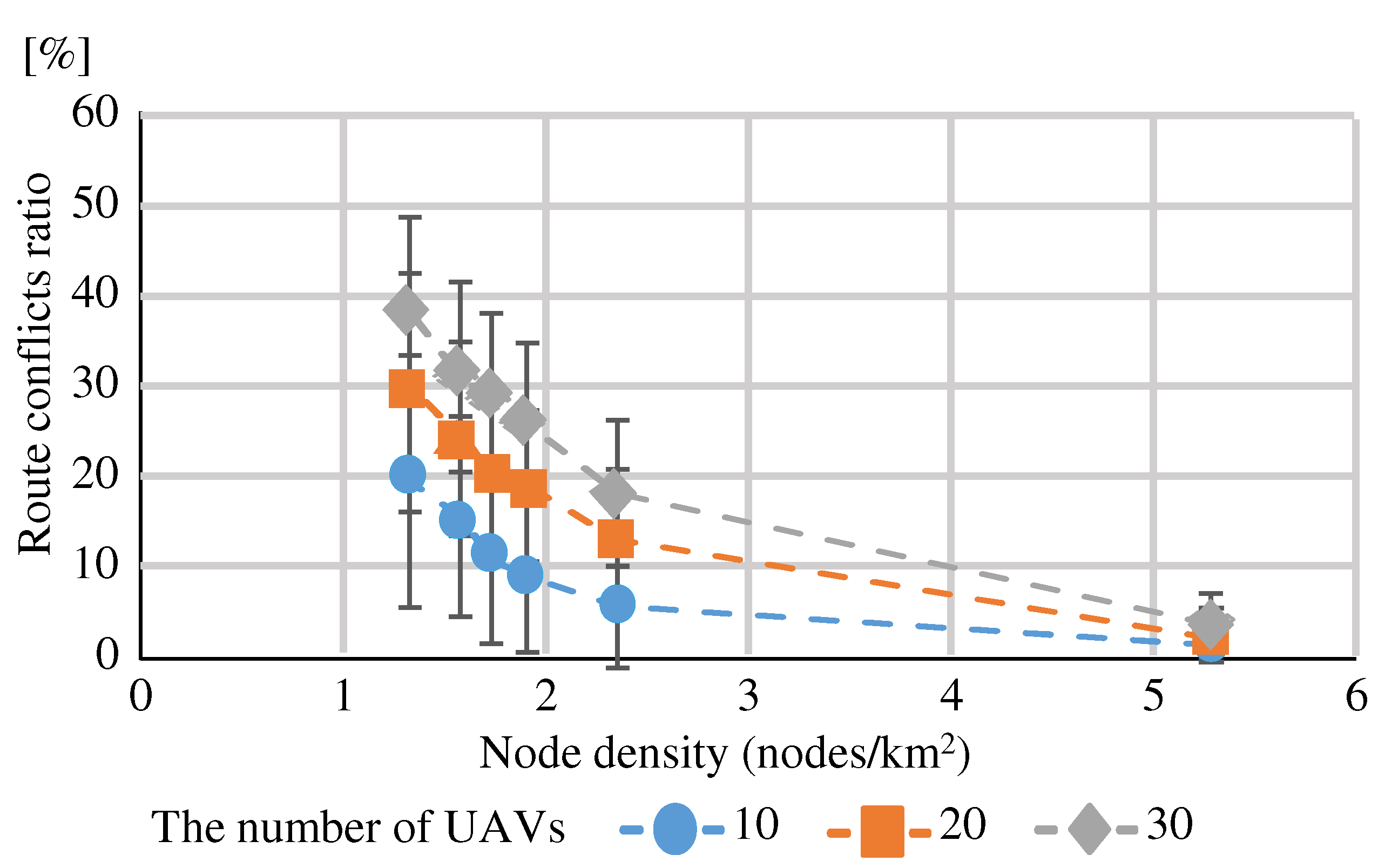
To suppress the “Route conflicts ratio”, a node density greater than is desirable, considering both routes between sparsely populated regions nodes and routes between population-dense regions nodes. “Using MPR” can reduce the number of relay nodes to nearly 70%, but since the node density must be greater than , it was found that the node density to which “Using MPR” should be applied is or greater.
7. Conclusions
In order to construct an efficient network suitable for UAV route construction, we proposed the following methods for selecting nodes to operate the relay function: “Randomly Selecting”, “More adjacent nodes”, “Fewer adjacent nodes”, and “Using MPR”. Evaluation experiments confirmed that “Using MPR” is the best way to construct a safer route with less total distance, while always meeting the requirements. We confirmed that “Using MPR” should be applied when the node density is greater than to suppress “Route conflicts”.
We evaluated the “Relay function activation cut-off value”, but did not evaluate the number of control messages and link crossings, so further evaluation and analysis will be conducted. Although there were limitations due to “Route conflicts”, it is desirable to establish a method to suppress “Route conflicts” by overlaying multiple routes at high altitudes in the airspace for further study.
Author Contributions
Conceptualization, S.O. and K.U.; methodology, S.O and K.U..; software, S.O.; validation, S.O., T.Y. and R.Y.; formal analysis, S.O., T.Y. and R.Y.; investigation, T.S, T.Y and R.Y.; resources, K.U.; data curation, S.O.; writing—original draft preparation, S.O.; writing—review and editing, K.U, T.M, T.Y and R.Y.; visualization, S.O.; supervision, K.U and T.M.; project administration, K.U.; funding acquisition, K.U. All authors have read and agreed to the published version of the manuscript.
Funding
This work was supported by JSPS Grant-in-Aid for Scientific Research JP24K14922.
Data Availability Statement
Data are contained within the article.
Acknowledgments
We would like to thank Mr. Haruki Gunji, a former member of our laboratory, for his great efforts.
Conflicts of Interest
All authors declare that the research was cunducted in the absence of any commercial or financial relationship that could be costructed sa a potencial conflict of interest.
References
- Ueda, K.; Miyoshi, T. Autonomous Navigation Control of UAV Using Radio Smart Meter Devices. J. of Telecommun. & Inform. Technol., The Nat. Institute of Telecommun., Republic of Poland, July 2019, 2, 64–72. [Google Scholar]
- Clausen T., H.; Jacquet, P. Optimized Link State Routing Protocol (OLSR). IETF, RFC3626, Oct. 2003.
- Perkins C. E.; B.-Royer E. M.; Das S. R. Ad hoc On-Demand Distance Vector (AODV) Routing. IETF, RFC3561, July 2003.
- Gunji H.; Yamazaki T.; Yamamoto R.; Miyoshi T.; Ueda K. Proactive Route Construction for UAV Delivery considering Distance and Safety using Wireless Multi-hop Network. <italic>IEICE Commun. Exp.</italic>, April 2022, 11. 7, 411–416.
- Kokubun, Y.; Yamazaki, T.; Yamamoto, R.; Miyoshi, T.; Ueda, K. Reactive Route Construction for UAV Delivery considering Travel Time and Safety using Wireless Multi-hop Network. IEICE Commun. Exp., April 2022, 11(7), 405–410. [Google Scholar] [CrossRef]
- Dijkstra E., W. ; A note on two problems in connexion with graphs. Numerische Mathematik, Dec. 1959, 1, 1, 269–271. [Google Scholar] [CrossRef]
- ns-3 Network Simulator, https://www.nsnam.org/, (accessed on 10th June 2024).
- Jiang, M.; Li, J.; , Tay Y. C. Cluster Based Routing Protocol (CBRP). IETF, INTERNET-DRAFT, Aug. 1999.
- Narumi, H.; Shiraishi, Y.; Takahashi, O. A Reliable Cluster-based Routing Algorithm for MANET. in Proc. of the Int. Worksh. on Informat., 2009, 44–51.
- Heinzelman W., R.; Chandrakasan, A.; Balakrishnan, H. Energy-Efficient Communication Protocol for Wireless Microsensor Networks. Proc. of the 33rd Hawaii Int. Conf. on System Sciences, Jan. 2000 1–10. [CrossRef]
- Mody, S.; Mirkar, S.; Ghag, R.; Kotecha, P. Cluster Head Selection Algorithm For Wireless Sensor Networks Using Machine Learning. Int. Conf. on Comp. Perform. Eval. (ComPE), Dec. 2021. [CrossRef]
Figure 1.
UAV navigation path construction by wireless multi-hop network.
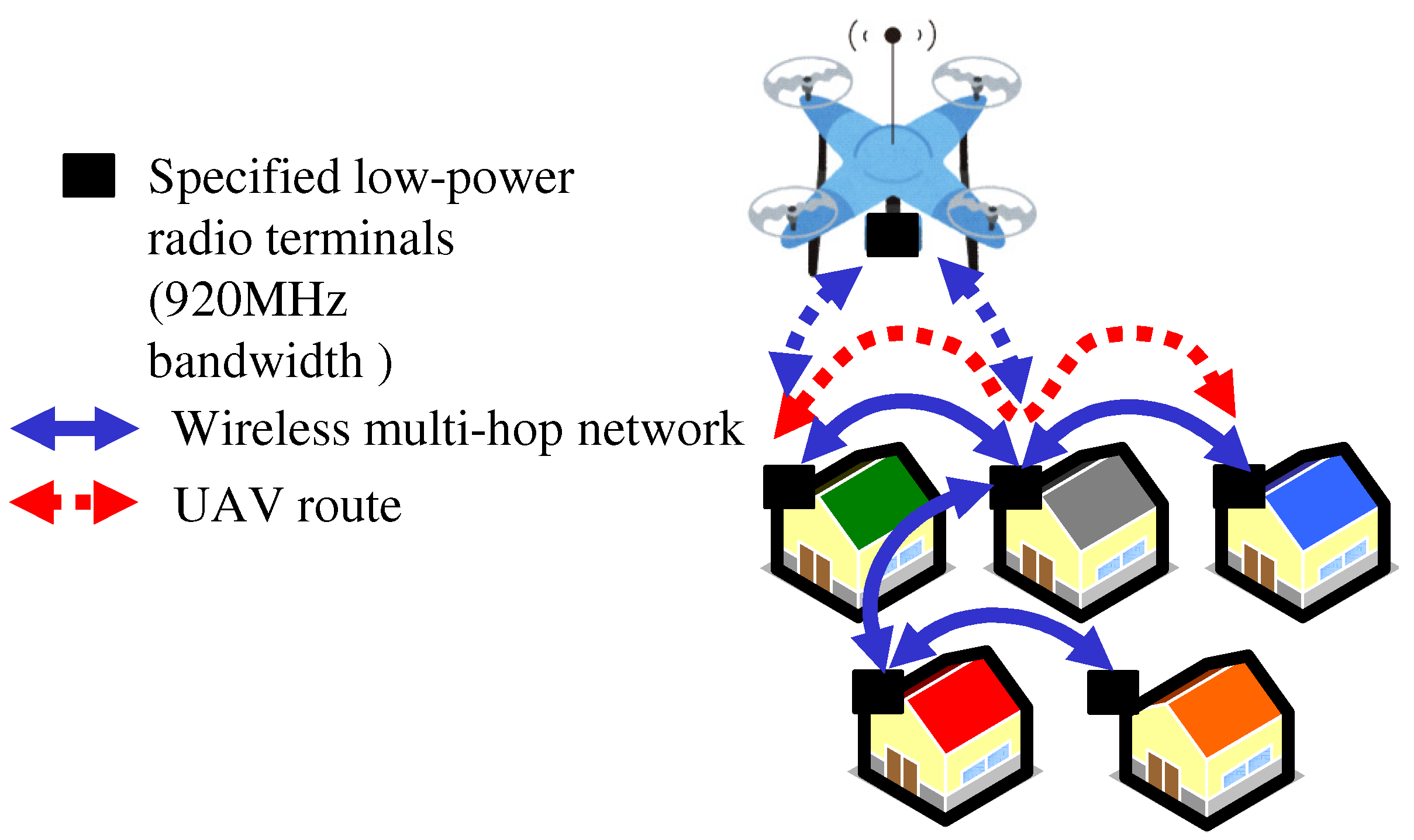
Figure 2.
Network configuration suitable for UAV routing.
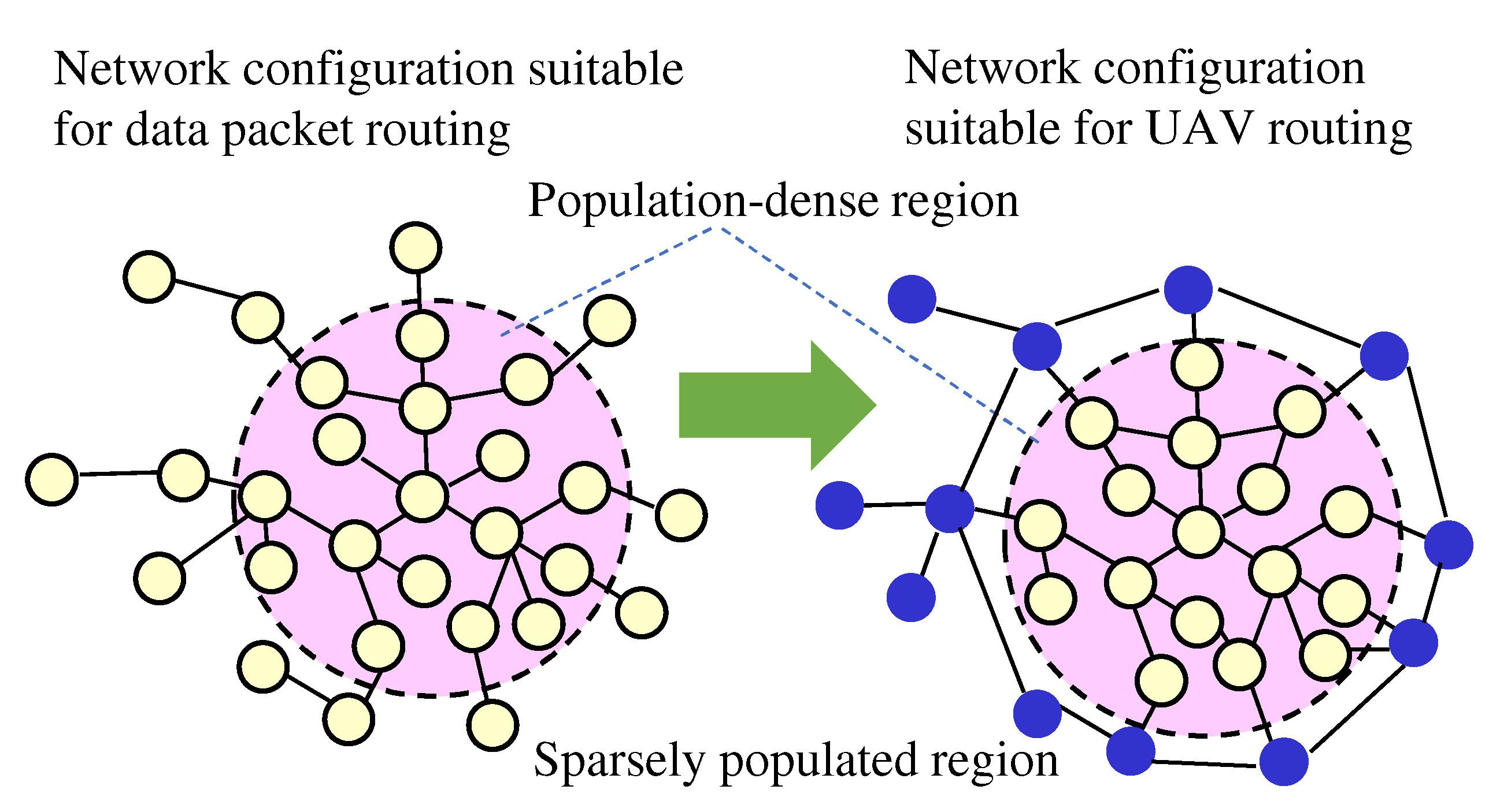
Figure 3.
Method for constructing optimal routes based on OLSR.
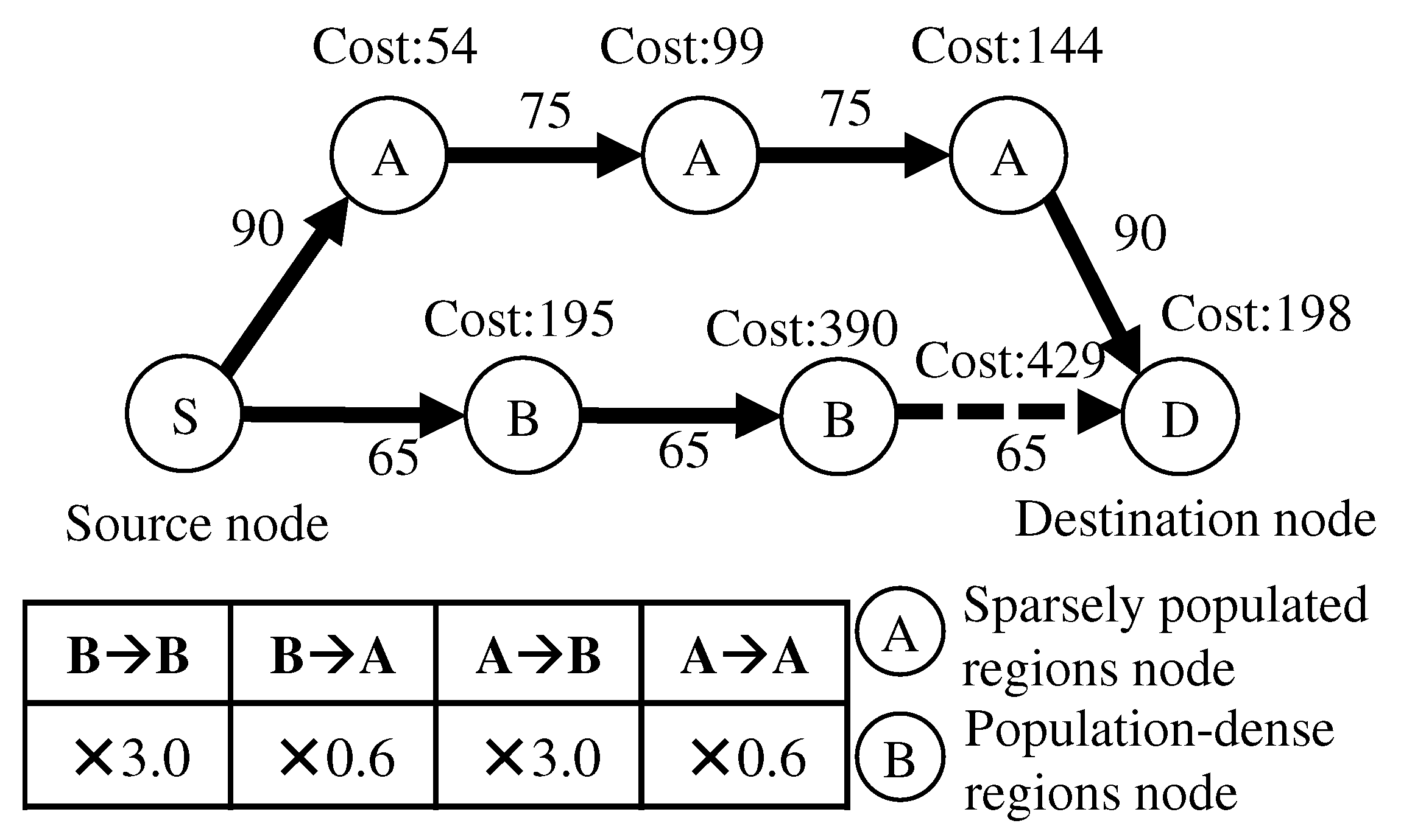
Figure 4.
Models of each node location.
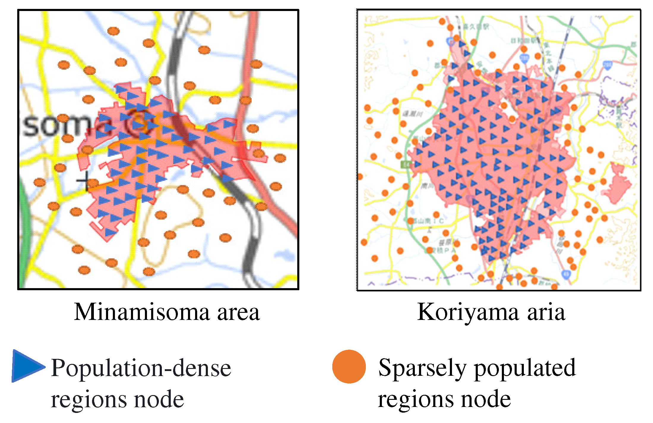
Figure 5.
Image of simplified network.
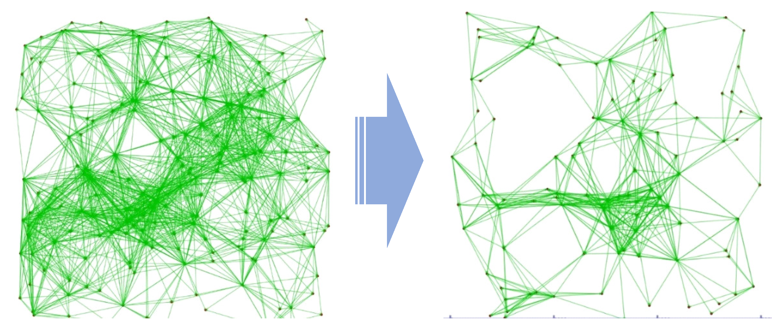
Figure 6.
Method of selecting nodes that connect to more adjacent nodes.
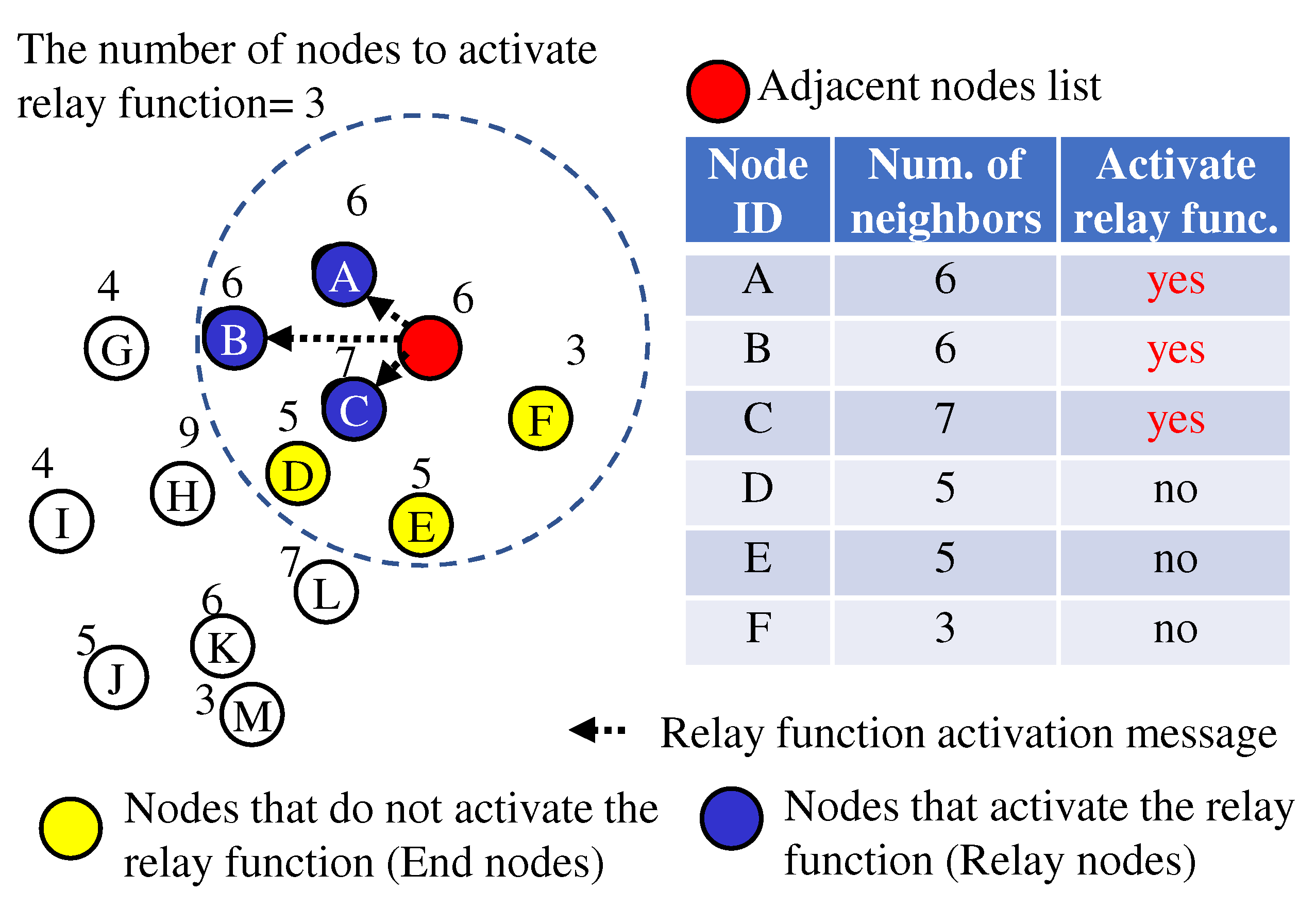
Figure 7.
Method of selecting nodes that connect to fewer adjacent nodes.
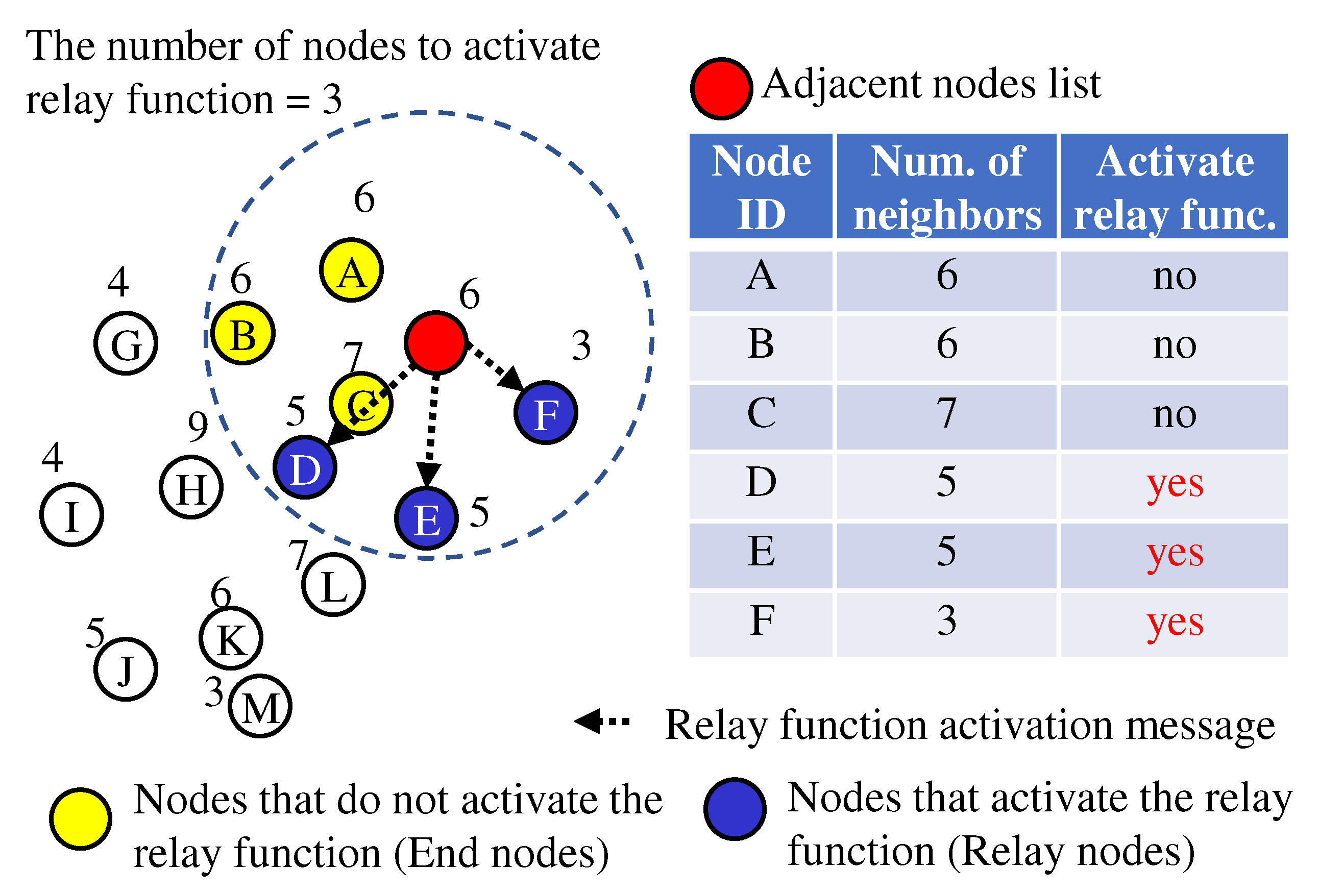
Figure 8.
Method using MPR.
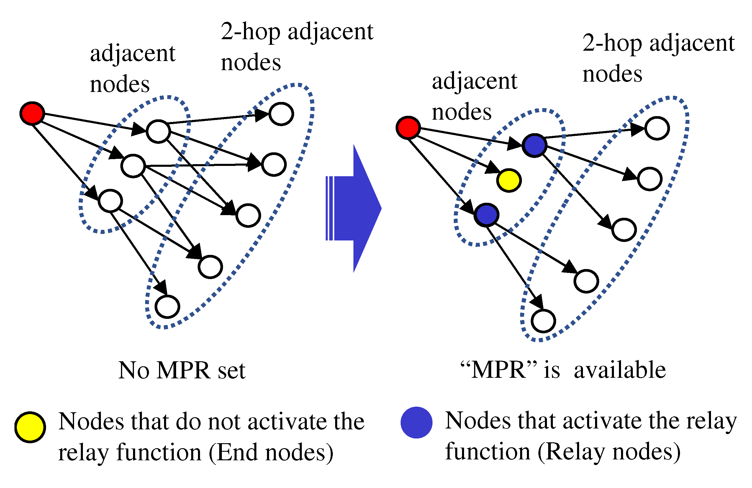
Figure 9.
Random node placement model.
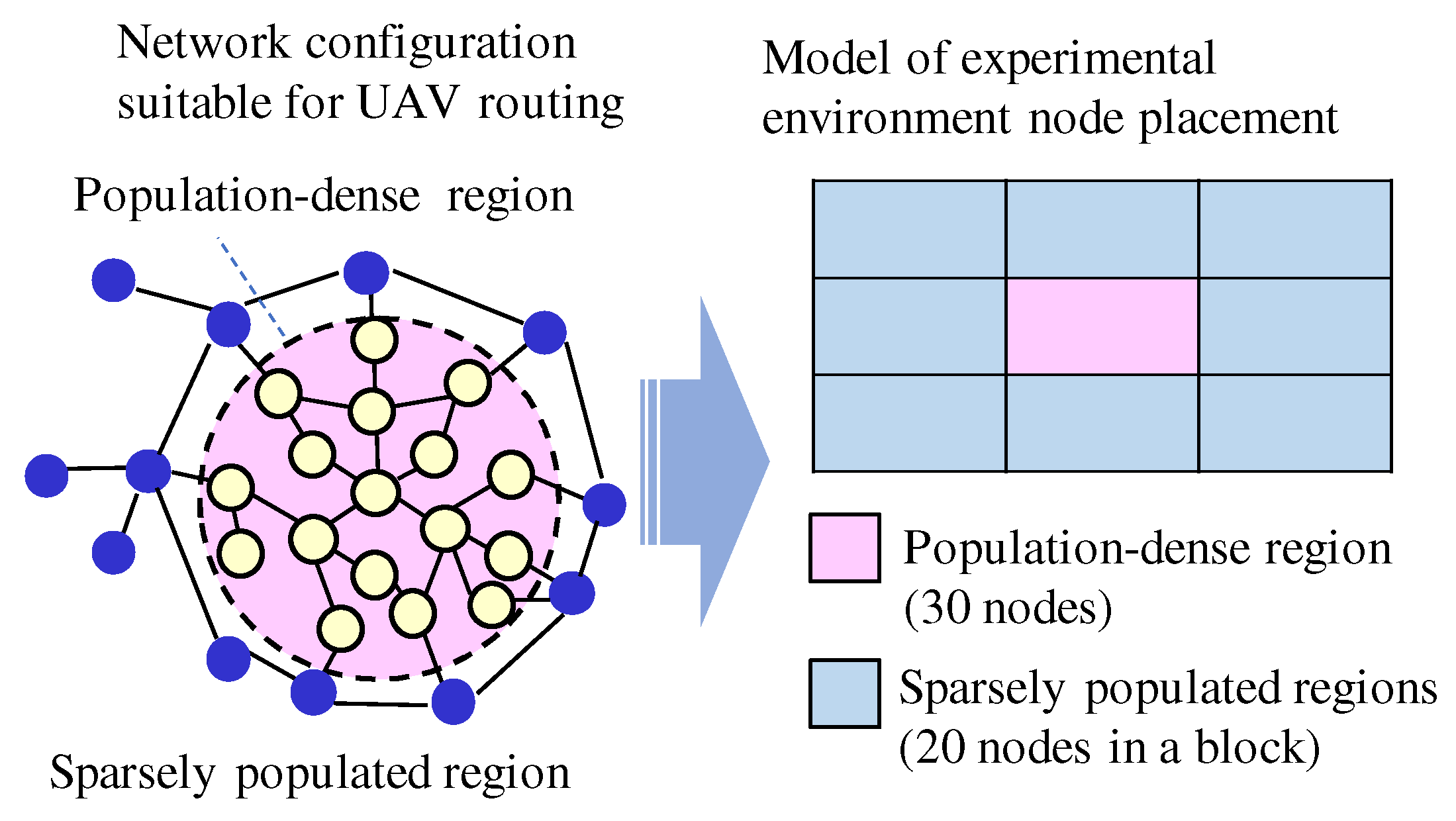
Figure 10.
“Randomly Selecting”’ - “Cluster split ratio” at “Relay function activation cut-off value”.
Figure 10.
“Randomly Selecting”’ - “Cluster split ratio” at “Relay function activation cut-off value”.
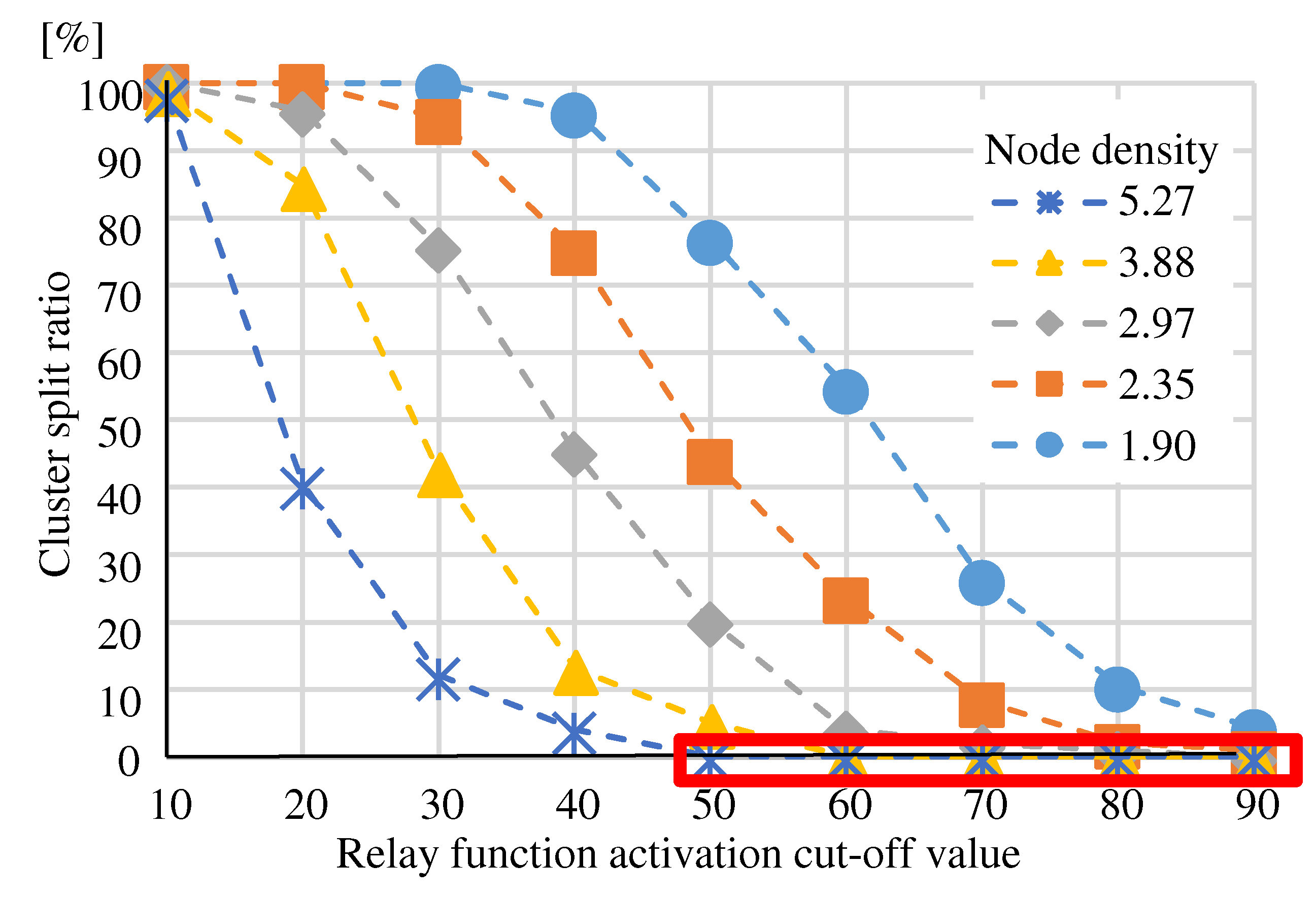
Figure 11.
“Randomly Selecting” - “The number of isolated nodes” at “Relay function activation cut-off value”.
Figure 11.
“Randomly Selecting” - “The number of isolated nodes” at “Relay function activation cut-off value”.
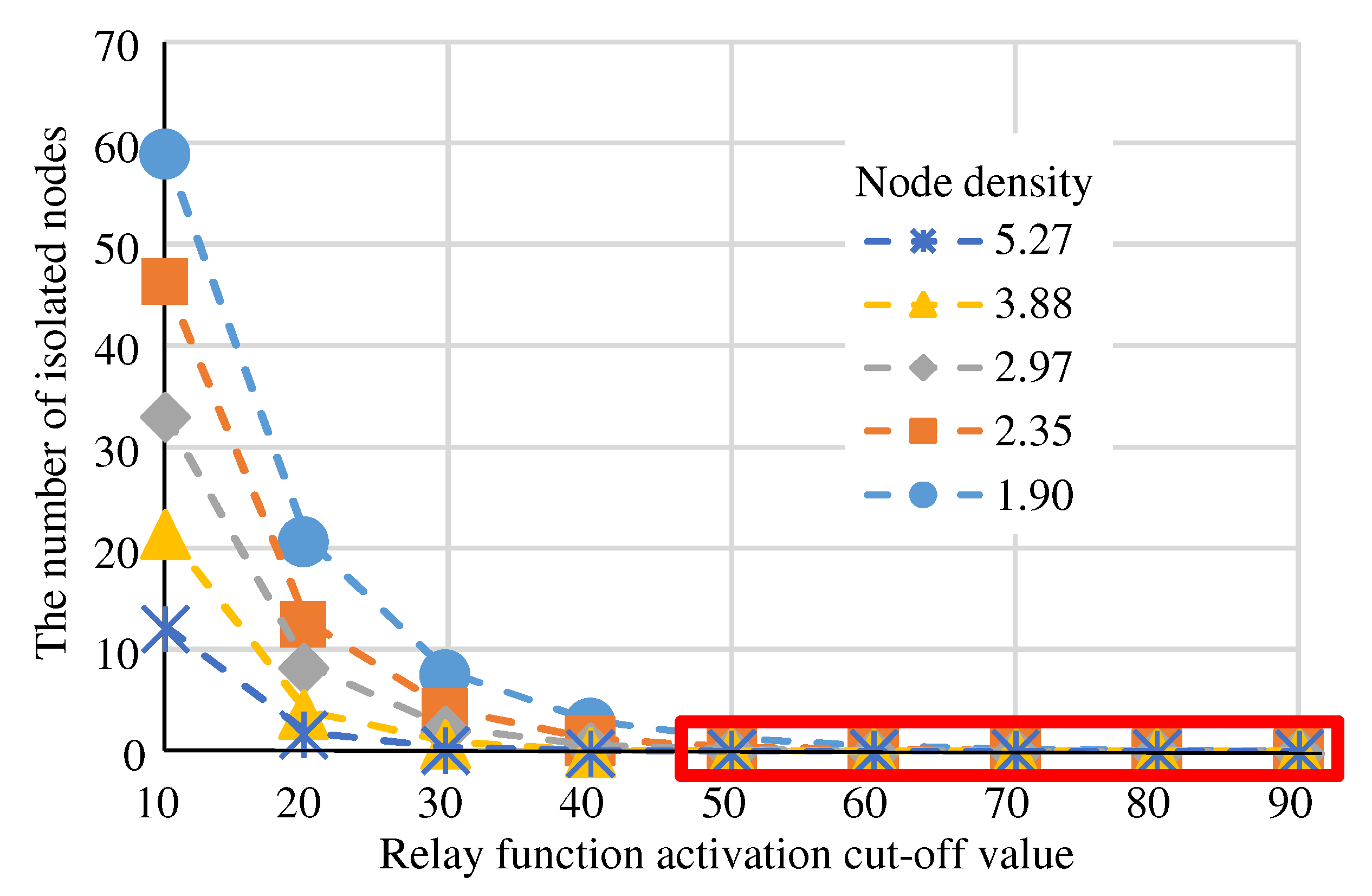
Figure 12.
“Randomly Selecting” - “Ratio to activate relay function” at “Relay function activation cut-off value”.
Figure 12.
“Randomly Selecting” - “Ratio to activate relay function” at “Relay function activation cut-off value”.
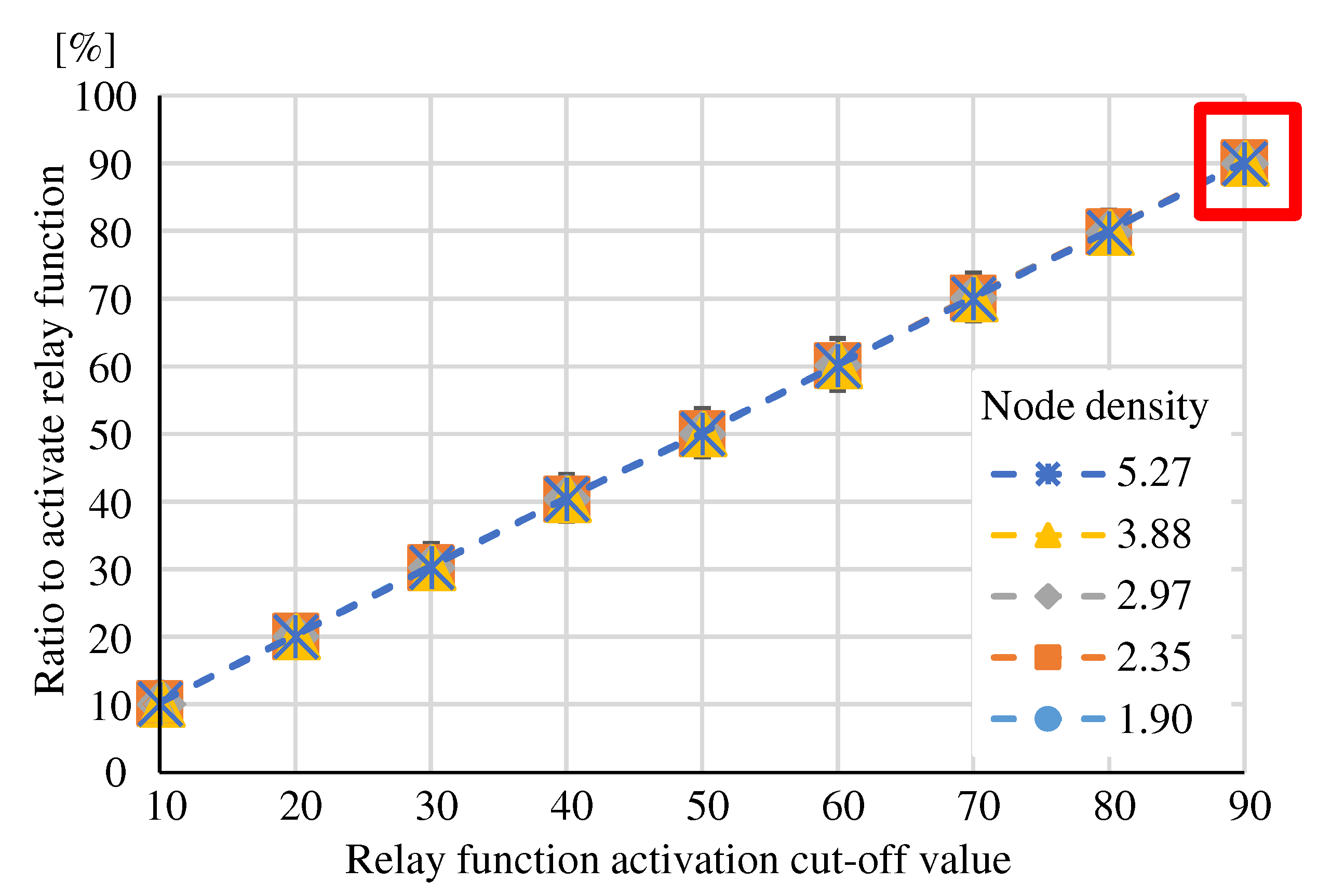
Figure 13.
“More adjacent nodes” - “Cluster split ratio” in “The number of nodes to activate relay function”.
Figure 13.
“More adjacent nodes” - “Cluster split ratio” in “The number of nodes to activate relay function”.
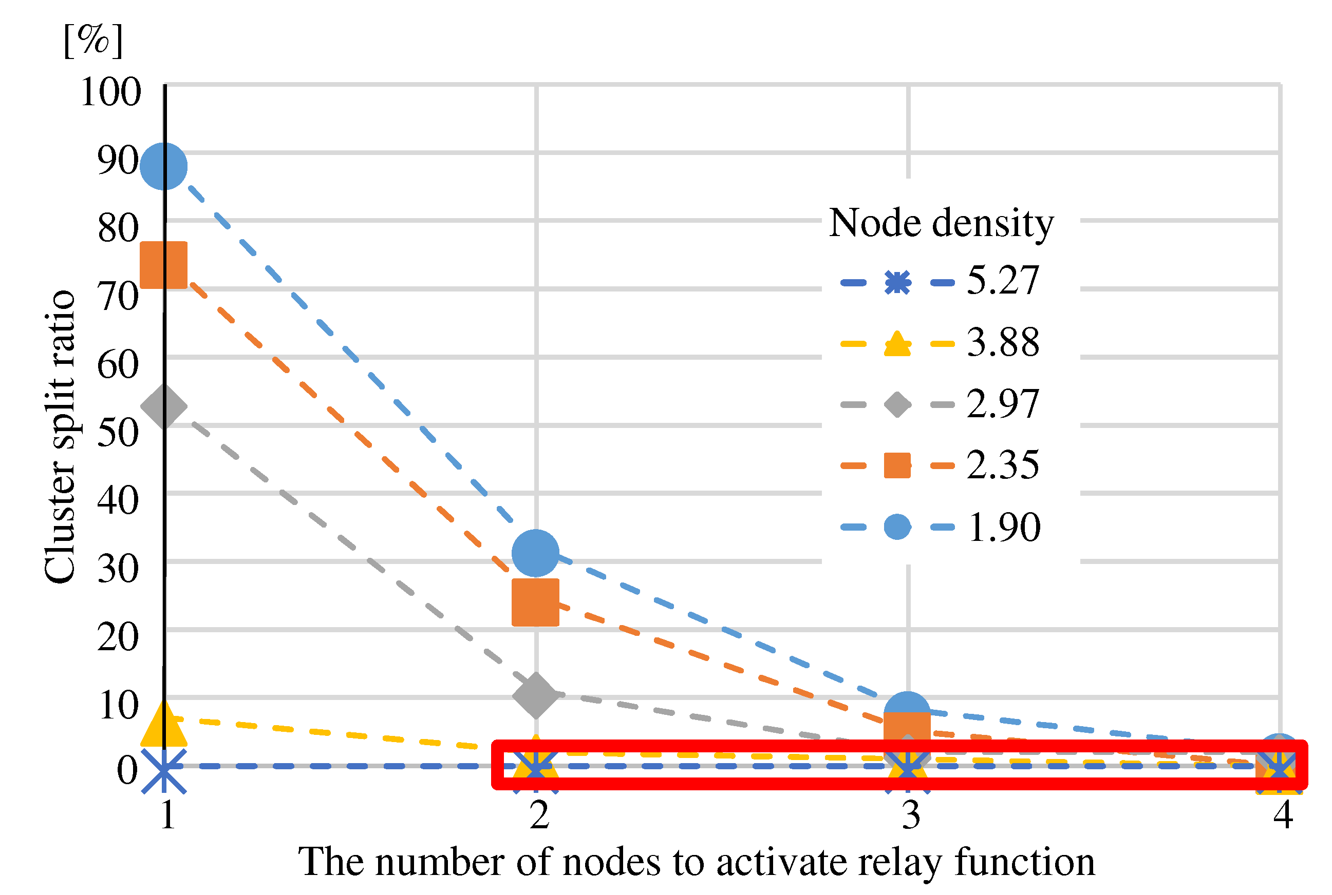
Figure 14.
“More adjacent nodes” - “Ratio to activate relay function” in “The number of nodes to activate relay function”.
Figure 14.
“More adjacent nodes” - “Ratio to activate relay function” in “The number of nodes to activate relay function”.
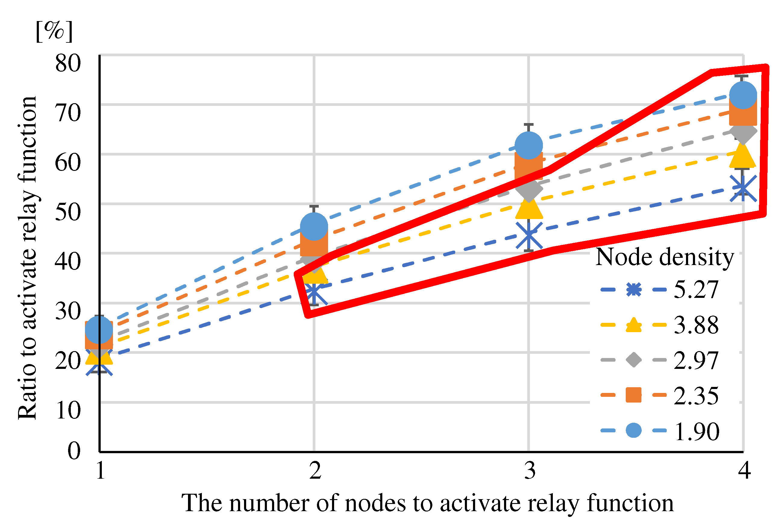
Figure 15.
“Fewer adjacent nodes” - “Cluster split ratio” in “The number of nodes to activate relay function”.
Figure 15.
“Fewer adjacent nodes” - “Cluster split ratio” in “The number of nodes to activate relay function”.
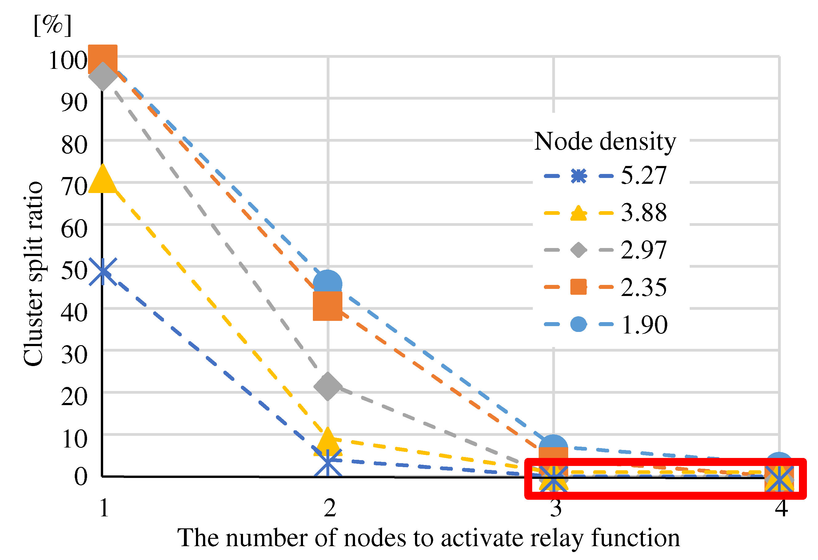
Figure 16.
“Fewer adjacent nodes” - “Ratio to activate relay function” in “The number of nodes to activate relay function”.
Figure 16.
“Fewer adjacent nodes” - “Ratio to activate relay function” in “The number of nodes to activate relay function”.
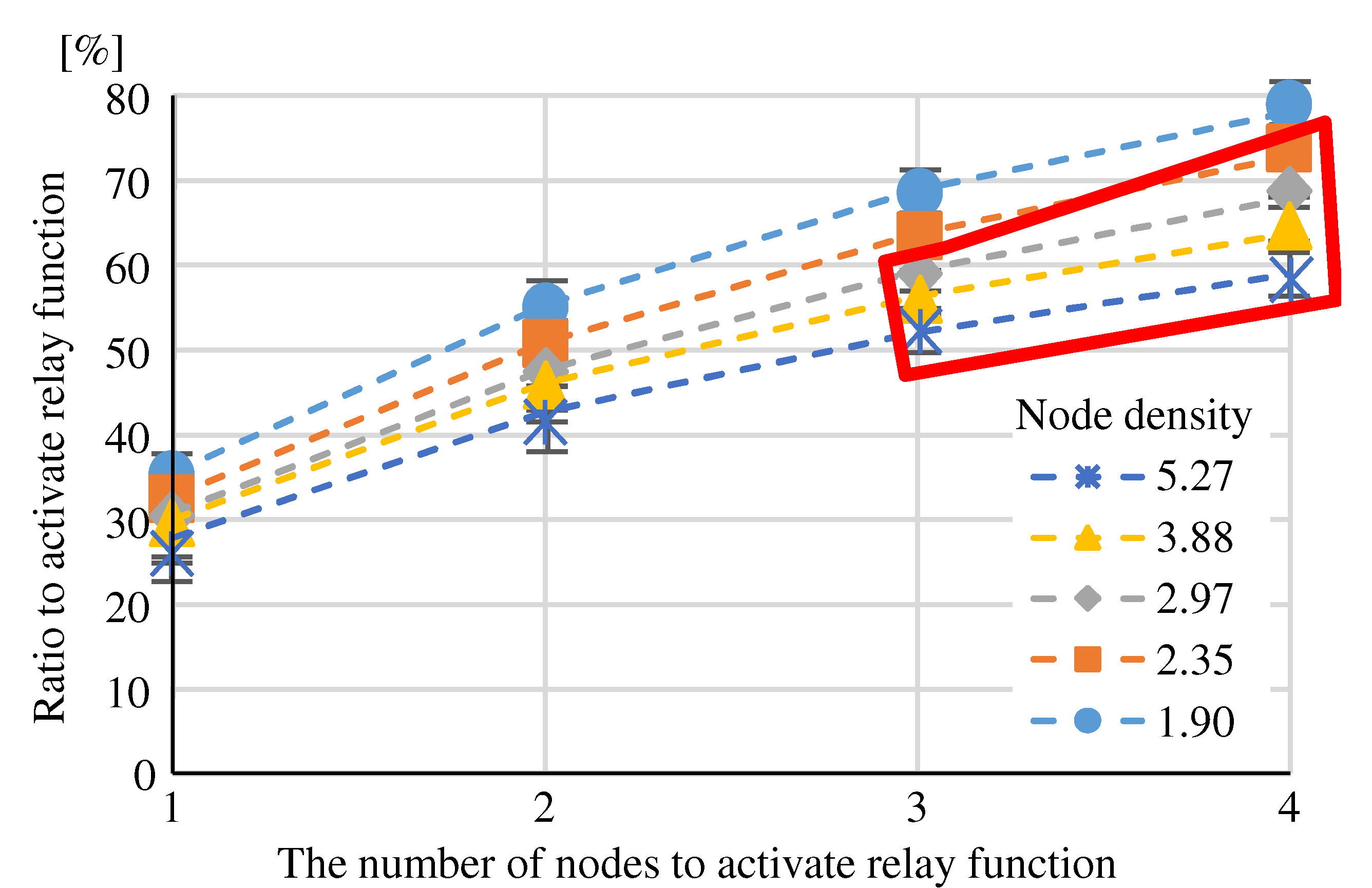
Figure 17.
“Using MPR” - “Ratio to activate relay function” at node density.
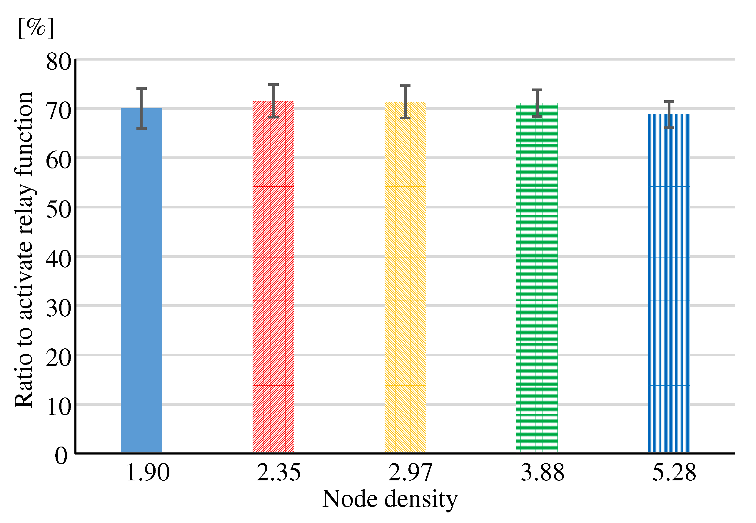
Figure 18.
“Ratio to activate relay function” in each method.
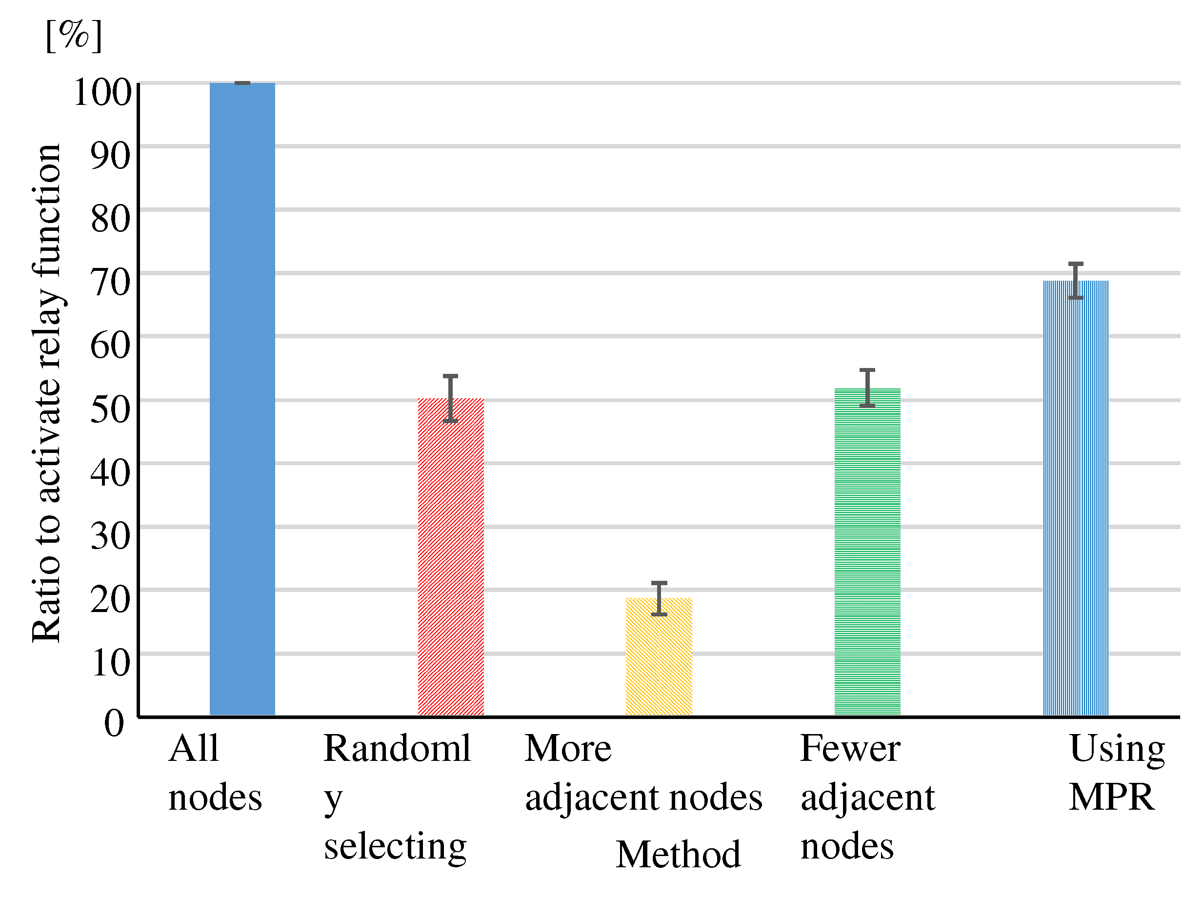
Figure 19.
“Total distance” in each method.
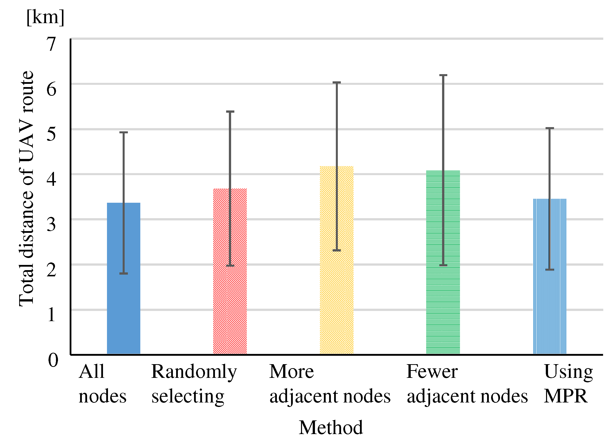
Figure 20.
“Population-dense regions distance” in each method.
Figure 21.
“Route conflicts ratio” at node density (between sparsely populated regions nodes).

Table 1.
Node arrangement models in Eval.1 to 4.
| Node density | Model size | Applicable experiments |
|---|---|---|
| [/km2] | [km2] | Eval.1 to 4 |
| 12km km | Eval.4 | |
| 11km km | Eval.4 | |
| km km | Eval.4 | |
| 10km km | Eval.1-4 | |
| 9km km | Eval.1-4 | |
| 8km km | Eval.1-3 | |
| 7km km | Eval.1-3 | |
| 6km km | Eval.1-4 |
Disclaimer/Publisher’s Note: The statements, opinions and data contained in all publications are solely those of the individual author(s) and contributor(s) and not of MDPI and/or the editor(s). MDPI and/or the editor(s) disclaim responsibility for any injury to people or property resulting from any ideas, methods, instructions or products referred to in the content. |
© 2024 by the authors. Licensee MDPI, Basel, Switzerland. This article is an open access article distributed under the terms and conditions of the Creative Commons Attribution (CC BY) license (http://creativecommons.org/licenses/by/4.0/).
Copyright: This open access article is published under a Creative Commons CC BY 4.0 license, which permit the free download, distribution, and reuse, provided that the author and preprint are cited in any reuse.
Submitted:
19 June 2024
Posted:
20 June 2024
You are already at the latest version
Alerts
This version is not peer-reviewed
Submitted:
19 June 2024
Posted:
20 June 2024
You are already at the latest version
Alerts
Abstract
Unmanned delivery technology using unmanned aerial vehicles (UAVs) has the potential to solve issues such as traffic congestion and labor shortages. We investigated a method to construct a route between the source and destination nodes in a wireless multi-hop network by installing a radio terminal in each house. If the relay functions of all nodes in the network are in operation, the number of control messages for route construction increases, and the message relay forwarding load of each node increases. Keeping all node pairs multi-hop connectivity, we establish a method to operate the relay function with as few nodes as possible. End nodes that have not activated the relay function connect to the relay node with the closest physical distance. In this paper, we propose methods for selecting nodes to operate the relay function. Specifically, one method is based on random selection, another method is based on the number of adjacent nodes, and a third method is based on the Multipoint Relay (MPR) of the Optimized Link State Routing Protocol (OLSR). For each method, we evaluate whether the route construction is available, the number of relay nodes, the total distance of constructed routes, and the distance in population-dense regions. We clarify the characteristics of each method, and the method based on MPR is the best for constructing a network suitable for UAV navigation routes. In addition, the smaller the number of relay nodes, the more unexpected collisions on the links due to route conflicts. We clarify the minimum node density required to apply the MPR method which reduces the number of relay nodes suppressing route conflicts.
Keywords:
Subject: Computer Science and Mathematics - Computer Networks and Communications
1. Introduction
As the number of parcel deliveries increasing every year, the logistics industry faces problems such as traffic congestion and labor shortages due to aging and decreasing truck drivers. Unmanned delivery technology using unmanned aerial vehicles (UAVs) can solve these problems.
Currently, any UAV can fly freely in approved airspace. Aircraft navigate on normal routes that connect air navigation radio facilities allowing many aircraft to fly safely without collision. In the future, when a large number of UAVs fly over the ground for home delivery, “Route in the Air” will be necessary, just like aircraft normal routes.
In Japan, smart meter networks are becoming popular, in which radio terminals are installed in each house to collect electricity consumption via wireless multi-hop. This indicates that wireless multi-hop routing between all the houses is possible if a radio terminal is installed in each house.
Therefore, we have investigated a method to create a route between the source and destination nodes of delivery on a wireless multi-hop network. The nodes are radio terminals installed in each house and used instead of aircraft navigation radio facilities. The UAVs fly following the nodes on the route as if they were transmitting data packets [1].
Section 2 shows the safe and efficient route construction method for UAV navigation in a wireless multi-hop network. Section 3 presents the issue of this route construction method, to which this paper contributes. Section 4 presents related work on this issue. Section 5 presents proposed methods to solve this issue. Section 6 presents the evaluation results of these proposed methods and discussion, showing their effectiveness and characteristics. Section concludes the paper with a summary and future work.
2. Safe and Efficient UAV Route Construction Method over Wireless Multi-Hop Network
We investigate a method to construct safe and efficient navigation paths for UAVs over a multi-hop network with radio terminal nodes as shown in Figure 1.
2.1. UAV Navigation Network Topology
Mobile Ad-hoc Networks (MANET) are typical examples of network topology construction techniques for relaying multiple radio terminals. MANET routing protocols such as Optimized Link State Routing Protocol (OLSR) [2], which is a typical example of the proactive type, and Ad hoc On-Demand Distance Vector (AODV) Routing [3], which is a typical example of the reactive type, construct the shortest path between source and destination nodes, as shown on the left side of Figure 2.
The optimal route for UAV delivery should be safe and efficient. Route construction for UAVs requires to bypass nodes in population-dense regions as much as possible to ensure safety [1]. We have two levels of network configuration. Higher level is a transmission network of nodes in sparsely populated regions. This is used as the preferred route because it is safe. Lower level is an access network with nodes in population-dense regions that connect to the transmission network via the shortest path. The right side of Figure 2 shows an image of the network configuration suitable for UAV routing.
We have studied two protocols for UAV navigation. One is the method based on OLSR, which constructs routes using the Dijkstra method. The link cost is a danger-weighted distance [4]. The other is the method based on AODV, in which each relay node evaluates the received Route Request (RREQ) messages in terms of route safety and flight time. The relay node selects and forwards the better RREQ message to construct an optimal route [5]. In this paper, we use the OLSR-based method among the above two methods for the route construction experiments, so we describe its details in the next section.
2.2. Method for Constructing Optimal Routes in Terms of Distance and Safety Based on OLSR
We have proposed the OLSR-based method, in which each node constructs an optimal route that is both safe and shorter travel distance and periodically updates the optimal route [4].
2.2.1. Optimized Link State Routing Protocol (OLSR)
Because OLSR [2] creates the routing table in advance, the source node can send packets immediately after the communication request. Therefore, each node periodically sends HELLO and TC messages to update the routing table.
The HELLO message performs the task of link discovery, neighbor discovery and Multipoint Relay (MPR) set discovery. The HELLO message contains the address and other information of the node, and each node sends it to its adjacent nodes. Each node periodically sends and receives HELLO messages to obtain and update information called Local Link Information of its adjacent nodes.
The Local Link Information manages the relationship with the sender node of the HELLO message, that are the link set and the set of adjacent nodes. If the HELLO message contains information about the node two hops away, the receiving node updates the set of nodes two hops away and determines the MPR set.
TC messages perform the task of topology declaration (advertising link states). Each node sends a TC message after a certain period of time after sending a HELLO message. TC messages advertise topology information to the entire network by flooding. Each node sends TC messages periodically in the same manner as HELLO messages. Each node sends TC messages based on its Local Link Information. When each node receives a TC message, it updates the received topology set and updates its routing table.
MPR is one of the features of OLSR, which provides an efficient method of flooding TC messages to the entire network by specifying the nodes that forward TC messages as an MPR set.
2.2.2. Dijkstra Method
The Dijkstra method [6] is a popular shortest path algorithm. Each node can determine the minimum cost path between any nodes by inputting the cost of all links into the Dijkstra method.
Because OLSR evaluates routes by the number of hops, it cannot see the actual distance which is important for UAV delivery. The optimal route construction method for UAV delivery uses the Dijkstra method to construct a route that takes into account the UAV’s travel distance. In addition, by weighting the danger level with the distance of each link, this method can construct safe and short-distance routes.
2.2.3. Method for Constructing Optimal Routes Based on OLSR
All nodes are given information about whether they are located in sparsely populated regions or population-dense regions.
The OLSR-based method added parameters to the HELLO message header. One is the region information of the HELLO message sending node, the other are region information and inter-node distances corresponding to each adjacent node “Neighbor Interface Address”.
In order to search for the optimal route considering distance and safety, the distance and region information obtained from the HELLO message must be advertised to the entire network. Therefore, the region information of the sending node and the distance between nodes and the region information corresponding to the “Advertised Neighbor Main Address” are added to the TC message header.
When a node receives a HELLO and TC message, it updates the routing table for each node using the Dijkstra method, which uses the link cost as the danger-weighted distance for each link. Figure 3 shows the method based on OLSR for constructing optimal route. The link where the UAV moves toward the population-dense region is weighted by multiplying the distance by 3.0 to increase the cost because it is dangerous, and the link where the UAV moves toward the sparsely populated region is weighted by multiplying the distance by 0.6 to decrease the cost because it is safe.
We observed the distance from the source node to the destination node “Total distance” and the distance over population-dense regions “Population-dense regions distance” to see if we could construct a safe and short path. We created simulation software by adding the OLSR-based method to NS-3 [7] so that simulation experiments could be performed close to the actual environment. We conducted simulation experiments using a model in which each node was located in an actual area in Fukushima Prefecture. A cluster consists of about 100 houses, and one node per cluster has a relay function. Figure 4 shows the models of each node location.
3. Issue
In the previous study, we assumed about 100 houses as a cluster and assumed that the relay function was operated in one node per cluster, as shown in Figure 4. The evaluation method randomly selected the relay node. The reason for assuming one relay node per 100 houses was unclear.
If the relay functions of all nodes in the network are operational and the UAV route can be constructed through them, the optimal route is close to a smooth curve. However, as the number of relay nodes increases, the number of control messages to construct the route increases, and the message relay forwarding load of each node increases. In the OLSR-based method, the processing load of each node increases with the relay forwarding of TC messages flooding the entire network and the calculation of the weighted Dijkstra method. In the AODV-based method, the processing load of each node increases in the RREQ message evaluation process and the relay forwarding process due to the increase in the number of received RREQ messages.
Therefore, it is necessary to construct safe and efficient UAV routes after simplifying the network by selecting nodes that operate relay functions. End nodes that have not activated the relay function connect to the relay node with the closest physical distance. Figure 5 shows an image of the simplified network.
We establish a method to operate the relay function as few nodes as possible while keeping all node pairs in the network multi-hop connectable. In the network resulting from the above method, the routes constructed by the optimal route construction method must be safe and efficient, with shorter “Population-dense regions distance” and “Total distance”.
On the other hand, the smaller the number of relay nodes and the simpler the network, the fewer links are available for routes. As UAV home delivery becomes more widespread, the number of overlapping routes (hereafter “Route conflicts”) will increase as more UAVs fly over the same region at the same time and build routes, which may cause UAVs to collide with each other. We evaluate the incidence of “Route conflicts” corresponding to the node density and the number of concurrent UAVs flight.
From the perspective of sufficient number of relay nodes to avoid too many “Route conflicts”, we clarify the minimum node density in the network required to apply the method that reduces the number of relay nodes for control message suppression.
4. Related Works
Cluster Based Routing Protocol (CBRP) [8] is one of the protocols of MANET in a two-tier network configuration with multi-node clusters and inter-cluster connections. Within a cluster, routing is divided into a network layer and an upper layer, and inter-cluster routing is established at the network layer [9]. The Cluster Head acts as the GW of the cluster, has a relay function, and performs routing. This is a method in which clustering cope with the nodes movement, and suppresses long-distance communication load by cascading messages over short paths. The algorithm selects the node with the “lowest ID” among its adjacent nodes as the Cluster Head. In other words, CBPR randomly selects nodes to operate the relay function. Therefore, it is not clear whether CBPR is an optimal method for selecting relay nodes.
W.R. Heinzelman et al. proposed Low-Energy Adaptive Clustering Hierarchy (LEACH), a clustering-based protocol in sensor networks [10]. This protocol randomly rotates local cluster base stations (Cluster Heads) to distribute the energy load evenly among the sensors in the network.
S. Mody, et al. proposed an algorithm for energy-efficient selection of Cluster Heads in sensor network using the k-means method [11]. It applies machine learning to select nodes to build clusters, and to select the Cluster Heads from the clusters.
As the above two papers, there have been several studies on sensor networks that create clusters of nodes and provide relay function at the Cluster Head. These select relay nodes to increase the load distribution among nodes and to be efficient in terms of energy consumption, rather than to optimize the end-to-end route. As a result, these node selection algorithms are almost random.
5. Proposed Method
Four methods are proposed for selecting the node that operates the relay function, which serves as the UAV’s route, from among all the nodes in the network. By comparing these methods, we clarify a method to select a smaller number of relay nodes that can suppress the number of control messages forwarded in the network without splitting the network.
5.1. Method of Randomly Selecting Relay Nodes
Similar to the low-energy adaptive clustering method used in sensor networks [10,11], the idea was to avoid biasing the nodes that activate the relay function toward some regions or some types of nodes. We propose a method to randomly select nodes to activate the relay function (hereafter “Randomly selecting”). This method controls the number of relay nodes by setting a “Relay function activation cut-off value” as the percentage of relay nodes among all nodes in the network.
- (1)
- When each node is activated, a value from 1 to 100 is randomly selected.
- (2)
- The relay function is operated for the node whose value is less than the preset “Relay function activation cut-off value”.
5.2. Method of Selecting Nodes that Connect to More Adjacent Nodes
If relay nodes are connected to more nodes, many node pairs may be connected with one hop. This may result in an efficient network where each node can be multi-hop connected with fewer hops. Therefore, we propose a method of selecting nodes connected to more adjacent nodes to operate the relay function (hereafter “More adjacent nodes”).
- (1)
- The number of adjacent nodes can be obtained from the source address of the received HELLO message.
- (2)
- Each node sends the number of adjacent nodes to the adjacent nodes by HELLO messages.
- (3)
- As shown in Figure 6, each node selects the nodes among its adjacent nodes that have more adjacent nodes and notifies the selected nodes that they should activate the relay function. Each node is set “The number of nodes to activate relay function” in advance.
- (4)
- The selected nodes activate the relay function.
5.3. Method of Selecting Nodes that Connect to Fewer Adjacent Nodes
Considering the safety of the UAV route, it is desirable to select nodes in regions with low node density and activate the relay function preferentially. Therefore, we propose a method to activate the relay function of nodes with fewer adjacent nodes (hereafter “Fewer adjacent nodes”).
The procedure for “Fewer adjacent nodes” is almost the same as that for “More adjacent nodes”. The only difference is that in (3) “Fewer adjacent nodes” selects the nodes with fewer adjacent nodes, while “More adjacent nodes” selects the nodes with more adjacent nodes. Figure 7 shows the “Fewer adjacent nodes”.
5.4. Method Using MPR
The MPR of OLSR can connect all 2-hop adjacent nodes, and by eliminating redundant relay nodes, it can suppress flooding and wasteful messages. We considered MPR as a reference for constructing an efficient and reliable relay network for UAVs. Therefore, we propose a method for selecting nodes to activate the relay function using the MPR concept (hereafter “Using MPR”).
- (1),(2)
- are the same as “More adjacent nodes”.
- (3)
- The node receiving a HELLO message knows which node is two hops away (2-hop adjacent node).
- (4)
- The node selects the minimum number of adjacent nodes (MPR set), they can connect to all 2-hop adjacent nodes as shown in Figure 8.
- (5)
- Starting from the node with the fewest adjacent nodes, the relay node (MPR set) is selected, and further relay nodes are selected from the MPR set, which propagate sequentially to select relay nodes for the whole network.
6. Evaluation
6.1. Evaluation Perspectives
We evaluate whether the proposed method can simplify the network and construct efficient routes while maintaining safety and network connectivity from the following evaluation perspectives.
6.1.1. Parameter Values that Meet Requirements
(Eval. 1) We clarify the parameter values for each proposed method that meets the requirement that there are no isolated nodes and that clusters are not split (i.e., relay nodes are connected to each other). We observe “Cluster split ratio” and “The number of isolated nodes” for each method. The “Cluster split ratio” is calculated by (the number of times the cluster split occurred) / (100 times, the total number of simulations run under the same conditions).
6.1.2. Ratio to Activate Relay Function
(Eval. 2) We evaluate how much the “Ratio to activate relay function” decreases with each method. It is calculated by (the number of relay nodes) / (the number of all nodes).
6.1.3. Optimality of the Route
(Eval. 3)
We evaluate optimality of the route constructed after the selection of relay nodes by each method, in terms of “Total distance” and “Population-dense regions distance” of UAV route’ from the source node to the destination node.
6.1.4. Route Conflicts Ratio at Relay Nodes Density
(Eval. 4) We clarify the “Route conflicts ratio” decreases as the relay node density increases depending on the number of UAVs, and clarify a sufficient node density to avoid too many “Route conflicts”.
6.2. Evaluation Method
For Eval. 1 and Eval. 2, we created a simulator in C++ to experiment about relay node selection by each method. In addition to the four proposed methods, we also experimented with a method in which all nodes have the relay function enabled (hereafter “All nodes”).
Simulation experiments were carried out using the node placement model in Figure 9. A population-dense region is located in the center, surrounded by sparsely populated regions. 30 nodes were placed in densely populated areas and 20 nodes in each of 8 blocks in sparsely populated areas.
Depending on Eval.1 to 4, the simulation randomly places nodes in each block with the node densities shown in Table 1. For Eval. 4, it is necessary to measure the characteristics of low node density in detail. We have assumed node placement models in which a node is placed out of every 100 houses in various local towns.
Eval. 3 and Eval. 4 use the OLSR-based method for route construction. Using the NS-3 network simulator, we modified the OLSR simulation software to add the signal processing and information repository of the OLSR-based method, and conducted simulation experiments.
Eval. 3 randomly selects source and destination nodes from sparsely populated regions. Eval. 4 randomly selects source and destination nodes from both population-dense regions and sparsely populated regions.
The radio propagation range of each node is 1.5 km, and nodes are not added, deleted, or moved. We repeat the relay node selection and route construction 100 times for each method and obtain the mean and standard deviation for each evaluation perspective.
6.3. Evaluation Results
6.3.1. Parameter Values That Meet Requirements, Ratio to Activate Relay Function
Method of Randomly Selecting Relay Nodes
(Eval. 1) For “Randomly Selecting”, Figure 10 shows “Cluster split ratio” and Figure 11 shows “The number of isolated nodes” for “Relay function activation cut-off value” at each node density. The “Cluster split ratio” in Figure 10 is the percentage of experiments in which cluster splitting occurred out of 100 experiments. The red box indicates the regions that meet the requirements. When the “Relay function activation cut-off value” was about 50, “The number of isolated nodes” was almost zero. However, setting the “Relay function activation cut-off value” to 50 was not sufficient to meet all requirements, as cluster splitting is likely to occur in models with low node density. Since node density has a significant impact on the “Cluster splitting ratio”, the “Relay function activation cut-off value” should be set to a value corresponding to the node density. If the node density is 1.90, the “Relay function activation cut-off value” must be greater than 90 to prevent cluster splitting.
(Eval. 2) Figure 12 shows the “Ratio to activate relay function” at each “Relay function activation cut-off value”. The “Ratio to activate relay function” becomes close to 90% when the “Relay function activation cut-off value” is greater than 90 to meet the requirement of no cluster splitting regardless of node density.
Method of Selecting Nodes that Connect to More Adjacent Nodes
(Eval. 1) In the “More adjacent nodes” and “Fewer adjacent nodes”, there are no isolated nodes because each node selects a relay node from its connected neighbors. As shown in Figure 13, the “Cluster split ratio” improves by about 50% as “The number of nodes to activate relay function” increases. Regardless of node density, it is expected that the requirements can be satisfied by selecting more than 4 nodes. Since node density has a significant impact on meeting the requirements, the “The number of nodes to activate relay function” should also be set to a value corresponding to node density.
(Eval. 2) The red box in Figure 14 indicates the “Ratio to activate relay function” to satisfy the requirement in all node densities. The “Ratio to activate relay function” to satisfy the requirement is lower than that of “Randomly Selecting”, which indicates that “More adjacent nodes” is more suitable for selecting relay nodes.
Method of Selecting Nodes that Connect to Fewer Adjacent Nodes
(Eval. 1) As shown in Figure 15, “Fewer adjacent nodes” has a higher “Cluster split ratio” than “Randomly Selecting” and “More adjacent nodes”. Compared to other methods, “Fewer adjacent nodes” is more difficult to meet the requirements.
(Eval. 2) As shown in Figure 16, “Fewer adjacent nodes” causes higher “Cluster split ratio” than the other methods, and also had a higher “Ratio to activate relay function” than “More adjacent nodes”. “Fewer adjacent node” proved to be a poor method.
Method Using MPR
(Eval. 1) With “Using MPR”, nodes are never isolated or clusters split, and requirements are always met.
(Eval. 2) Figure 17 shows the evaluation results of “Ratio to activate relay function”. Regardless of the node density, the “Ratio to activate relay function” is about 70%. Compared to other methods, “Using MPR” can suppress the “Ratio to activate relay function” in models with low node density. However, in models with high node density, the “Ratio to activate relay function” cannot be suppressed as much as the other methods.
6.3.2. Optimality of the Route
We selected relay nodes and constructed routes in the high node density 5.27 model, which could easily meet the requirements. To meet the requirements with this node density, we set the “Relay function activation cut-off value” to 50 for “Randomly Selecting”, set “The number of nodes to activate relay function” to 1 for “More adjacent nodes”, and set it to 4 for “Fewer adjacent nodes”.
Ratio to Activate Relay Function
(Eval. 2) As shown in Figure 18, for each method, the “Ratio of activate relay function” is significantly reduced compared to “All nodes”, which indicates that an efficient network can be constructed.
Total Distance
(Eval. 3) Figure 19 shows the “Total distance” of the routes constructed after selecting relay nodes by each method. In the “More adjacent nodes” and “Fewer adjacent nodes”, the “Total distance” increased by almost 1 km compared to the “All nodes”, since the “Ratio to activate relay function” decreased significantly. For all methods, the “Total distance” increased when the number of relay nodes was reduced. In particular, “More adjacent nodes” and “Fewer adjacent nodes” confirmed that the distance increased too much when the number of relay nodes was reduced too much. “Using MPR” resulted in a small reduction in the “Ratio to activate relay function”, but did not increase the “Total distance” and did not result in worse routing.
Population-Dense Regions Distance
(Eval. 3) Figure 20 shows the “Population-dense regions distance” of the constructed routes. The “All nodes“ did not construct any routes through the population-dense regions. However, the “More adjacent nodes” and “Fewer adjacent nodes” routes go through population-dense regions. Since “More adjacent nodes” gives priority to nodes with more adjacent nodes as relay nodes, nodes in population-dense regions are easily selected as relay nodes. Nodes in sparsely populated regions are less likely to be relay nodes. As a result, only large circuitous routes or short routes through population-dense regions can be constructed. The reason why the routes in “Fewer adjacent nodes” pass through the population-dense regions node is that nodes connected to the relay node in the population-dense regions have been likely selected as source and destination nodes.
Overall, the evaluation found that “Using MPR” was the most appropriate method.
6.3.3. Route Conflicts Ratio at Relay Nodes Density
(Eval. 4) Figure 21 shows the “Route conflicts ratio” at each node density. The source and destination nodes are located in sparsely populated regions. The experimental results confirm that the “Route conflicts ratio” increases as the node density decreases. When node density is low, nodes are sparsely and the number of adjacent nodes per node is small. Fewer adjacent nodes means fewer route candidates. This makes it easier to construct routes that relay certain nodes. As a result, “Route conflicts ratio” are likely to increase.
Figure 21 shows the “Route conflicts ratio” at each node density when the source and destination nodes are located in population-dense regions. The “Route conflicts ratio” was lower than that for route construction between nodes in sparsely populated regions. Although there were routes that bypassed nodes in population-dense regions, many routes were constructed in small population-dense regions. Therefore, the number of relay links in almost routes was low. There were few cases where multiple routes overlapped at relay links. As a result, the “Route conflicts ratio” was low. This suggests that “Route conflicts ratio” can be suppressed by constructing short-distance routes in addition to increasing node density.
Figure 22.
“Route conflicts ratio” at node density (between population-dense regions nodes).
To suppress the “Route conflicts ratio”, a node density greater than is desirable, considering both routes between sparsely populated regions nodes and routes between population-dense regions nodes. “Using MPR” can reduce the number of relay nodes to nearly 70%, but since the node density must be greater than , it was found that the node density to which “Using MPR” should be applied is or greater.
7. Conclusions
In order to construct an efficient network suitable for UAV route construction, we proposed the following methods for selecting nodes to operate the relay function: “Randomly Selecting”, “More adjacent nodes”, “Fewer adjacent nodes”, and “Using MPR”. Evaluation experiments confirmed that “Using MPR” is the best way to construct a safer route with less total distance, while always meeting the requirements. We confirmed that “Using MPR” should be applied when the node density is greater than to suppress “Route conflicts”.
We evaluated the “Relay function activation cut-off value”, but did not evaluate the number of control messages and link crossings, so further evaluation and analysis will be conducted. Although there were limitations due to “Route conflicts”, it is desirable to establish a method to suppress “Route conflicts” by overlaying multiple routes at high altitudes in the airspace for further study.
Author Contributions
Conceptualization, S.O. and K.U.; methodology, S.O and K.U..; software, S.O.; validation, S.O., T.Y. and R.Y.; formal analysis, S.O., T.Y. and R.Y.; investigation, T.S, T.Y and R.Y.; resources, K.U.; data curation, S.O.; writing—original draft preparation, S.O.; writing—review and editing, K.U, T.M, T.Y and R.Y.; visualization, S.O.; supervision, K.U and T.M.; project administration, K.U.; funding acquisition, K.U. All authors have read and agreed to the published version of the manuscript.
Funding
This work was supported by JSPS Grant-in-Aid for Scientific Research JP24K14922.
Data Availability Statement
Data are contained within the article.
Acknowledgments
We would like to thank Mr. Haruki Gunji, a former member of our laboratory, for his great efforts.
Conflicts of Interest
All authors declare that the research was cunducted in the absence of any commercial or financial relationship that could be costructed sa a potencial conflict of interest.
References
- Ueda, K.; Miyoshi, T. Autonomous Navigation Control of UAV Using Radio Smart Meter Devices. J. of Telecommun. & Inform. Technol., The Nat. Institute of Telecommun., Republic of Poland, July 2019, 2, 64–72. [Google Scholar]
- Clausen T., H.; Jacquet, P. Optimized Link State Routing Protocol (OLSR). IETF, RFC3626, Oct. 2003.
- Perkins C. E.; B.-Royer E. M.; Das S. R. Ad hoc On-Demand Distance Vector (AODV) Routing. IETF, RFC3561, July 2003.
- Gunji H.; Yamazaki T.; Yamamoto R.; Miyoshi T.; Ueda K. Proactive Route Construction for UAV Delivery considering Distance and Safety using Wireless Multi-hop Network. <italic>IEICE Commun. Exp.</italic>, April 2022, 11. 7, 411–416.
- Kokubun, Y.; Yamazaki, T.; Yamamoto, R.; Miyoshi, T.; Ueda, K. Reactive Route Construction for UAV Delivery considering Travel Time and Safety using Wireless Multi-hop Network. IEICE Commun. Exp., April 2022, 11(7), 405–410. [Google Scholar] [CrossRef]
- Dijkstra E., W. ; A note on two problems in connexion with graphs. Numerische Mathematik, Dec. 1959, 1, 1, 269–271. [Google Scholar] [CrossRef]
- ns-3 Network Simulator, https://www.nsnam.org/, (accessed on 10th June 2024).
- Jiang, M.; Li, J.; , Tay Y. C. Cluster Based Routing Protocol (CBRP). IETF, INTERNET-DRAFT, Aug. 1999.
- Narumi, H.; Shiraishi, Y.; Takahashi, O. A Reliable Cluster-based Routing Algorithm for MANET. in Proc. of the Int. Worksh. on Informat., 2009, 44–51.
- Heinzelman W., R.; Chandrakasan, A.; Balakrishnan, H. Energy-Efficient Communication Protocol for Wireless Microsensor Networks. Proc. of the 33rd Hawaii Int. Conf. on System Sciences, Jan. 2000 1–10. [CrossRef]
- Mody, S.; Mirkar, S.; Ghag, R.; Kotecha, P. Cluster Head Selection Algorithm For Wireless Sensor Networks Using Machine Learning. Int. Conf. on Comp. Perform. Eval. (ComPE), Dec. 2021. [CrossRef]
Figure 1.
UAV navigation path construction by wireless multi-hop network.
Figure 2.
Network configuration suitable for UAV routing.
Figure 3.
Method for constructing optimal routes based on OLSR.
Figure 4.
Models of each node location.
Figure 5.
Image of simplified network.
Figure 6.
Method of selecting nodes that connect to more adjacent nodes.
Figure 7.
Method of selecting nodes that connect to fewer adjacent nodes.
Figure 8.
Method using MPR.
Figure 9.
Random node placement model.
Figure 10.
“Randomly Selecting”’ - “Cluster split ratio” at “Relay function activation cut-off value”.
Figure 10.
“Randomly Selecting”’ - “Cluster split ratio” at “Relay function activation cut-off value”.
Figure 11.
“Randomly Selecting” - “The number of isolated nodes” at “Relay function activation cut-off value”.
Figure 11.
“Randomly Selecting” - “The number of isolated nodes” at “Relay function activation cut-off value”.
Figure 12.
“Randomly Selecting” - “Ratio to activate relay function” at “Relay function activation cut-off value”.
Figure 12.
“Randomly Selecting” - “Ratio to activate relay function” at “Relay function activation cut-off value”.
Figure 13.
“More adjacent nodes” - “Cluster split ratio” in “The number of nodes to activate relay function”.
Figure 13.
“More adjacent nodes” - “Cluster split ratio” in “The number of nodes to activate relay function”.
Figure 14.
“More adjacent nodes” - “Ratio to activate relay function” in “The number of nodes to activate relay function”.
Figure 14.
“More adjacent nodes” - “Ratio to activate relay function” in “The number of nodes to activate relay function”.
Figure 15.
“Fewer adjacent nodes” - “Cluster split ratio” in “The number of nodes to activate relay function”.
Figure 15.
“Fewer adjacent nodes” - “Cluster split ratio” in “The number of nodes to activate relay function”.
Figure 16.
“Fewer adjacent nodes” - “Ratio to activate relay function” in “The number of nodes to activate relay function”.
Figure 16.
“Fewer adjacent nodes” - “Ratio to activate relay function” in “The number of nodes to activate relay function”.
Figure 17.
“Using MPR” - “Ratio to activate relay function” at node density.
Figure 18.
“Ratio to activate relay function” in each method.
Figure 19.
“Total distance” in each method.
Figure 20.
“Population-dense regions distance” in each method.
Figure 21.
“Route conflicts ratio” at node density (between sparsely populated regions nodes).
Table 1.
Node arrangement models in Eval.1 to 4.
| Node density | Model size | Applicable experiments |
|---|---|---|
| [/km2] | [km2] | Eval.1 to 4 |
| 12km km | Eval.4 | |
| 11km km | Eval.4 | |
| km km | Eval.4 | |
| 10km km | Eval.1-4 | |
| 9km km | Eval.1-4 | |
| 8km km | Eval.1-3 | |
| 7km km | Eval.1-3 | |
| 6km km | Eval.1-4 |
Disclaimer/Publisher’s Note: The statements, opinions and data contained in all publications are solely those of the individual author(s) and contributor(s) and not of MDPI and/or the editor(s). MDPI and/or the editor(s) disclaim responsibility for any injury to people or property resulting from any ideas, methods, instructions or products referred to in the content. |
© 2024 by the authors. Licensee MDPI, Basel, Switzerland. This article is an open access article distributed under the terms and conditions of the Creative Commons Attribution (CC BY) license (http://creativecommons.org/licenses/by/4.0/).
Copyright: This open access article is published under a Creative Commons CC BY 4.0 license, which permit the free download, distribution, and reuse, provided that the author and preprint are cited in any reuse.
Novel Framework-Based Routing for Task-Adaptive Mobile Networks of Unmanned Aerial Vehicular
Zhe Chu
et al.
Electronics,
2022
LECAR: Location Estimation-Based Congestion-Aware Routing Protocol for Sparsely Deployed Energy-Efficient UAVs
Imtiaz Mahmud
et al.
Sensors,
2021
Position-Monitoring-Based Hybrid Routing Protocol for 3D UAV-Based Networks
Saif Ullah
et al.
Drones,
2022


MDPI Initiatives
Important Links
© 2024 MDPI (Basel, Switzerland) unless otherwise stated