1. Introduction
Liquid sodium is the coolant in sodium-cooled fast reactors. Many components of the reactor vessel, intermediate heat exchangers, cold traps in the fast reactor, and the measurement parts of its instruments, such as ultrasonic flow and hydrogen meters, are in contact with liquid sodium. The required liquid sodium wettability depends on the function of each component. For example, the ultrasonic flowmeter, which measures the flow velocity of liquid sodium, requires good wettability of the ultrasonic transmitting and receiving surfaces for immediate measurements. Hydrogen meters determine the change in the hydrogen concentration in liquid sodium. Pure nickel (Ni) is used as the material of the hydrogen permeable film of the hydrogen concentration meter, and its surface should have good wettability for immediate hydrogen detection. However, the narrow piping, valve, and component sections should have poor wettability to prevent residual sodium when sodium is drained. Thus, the required liquid sodium wettability differs depending on the components and their parts of the fast reactor; however, liquid sodium wettability has not been considered in the component design. If the liquid sodium wettability can be controlled to match the wettability requirements of the components, the safety and operational efficiency of fast reactors can be improved.
We investigated the relationship between the contact angle, which is the wettability of liquid sodium on pure metals and alloys, and the electronic state at the interface to control the wettability between liquid sodium and metals. The results showed that the contact angle relates to the atomic interactions at the interface. [
1,
2,
3,
4] Therefore, we considered that one way to control wettability is to control the electronic state, which is the atomic interaction at the interface. Furthermore, we focused on ion implantation technology to change the electronic state of metal surfaces.
Since ion implantation technology was developed for the development of semiconductor devices, many studies have investigated the changes in the electrical and other properties caused by ion implantation. [
5,
6,
7,
8,
9] Some studies have aimed to improve the corrosion properties of liquid sodium by ion implantation. [
10,
11,
12] However, no studies have investigated the change in the electronic state of the topmost surface of the substrate metal due to ion implantation. Because, it is presumed, it is difficult to model the atomic structure of ion implanted surfaces. It is very important to understand the electronic states of the interface which relate many characteristics.
The change in the wettability of materials by ion implantation has been previously reported. Liquid materials are primarily water, while many solid materials, such as metals, polymers, and nanoparticles, are used. X. Chen et al. reported that F, N, and F+N ions were implanted into a metallic material, stainless steel, to improve its water repellency. [
13] L. Rimondini et al. implanted oxygen ions into the biomaterial titanium (Ti), but the wettability showed little or no change. [
14] Y. Suzuki et al. reported that Na and K ions were implanted into polymer materials to improve wettability. [
15,
16] R. K. Y. Fu et al. found that implanting N
2 or N
2+O
2 into nylon improved the wettability. [
17] J. Jeon et al. reported that Xe ion implantation into Al(OH)
3 nanostructures drastically changed the contact angle. [
18] Although there have been no previous studies where sodium implantation has changed the wettability of liquid sodium and metals, the ion implantation technique is promising to change the wettability.
This study aims to theoretically calculate the electronic structure of the substrate metal interface due to sodium implantation and experimentally investigate the liquid sodium wettability of the substrate metal. Furthermore, the change in wettability due to sodium implantation is discussed from the viewpoint of the atomic interactions of the electronic states at the surface.
2. Theoretical calculation of the interface
2.1. Theoretical calculation method
The discrete variational (DV)-Xα cluster method, a molecular orbital method, was used to calculate the electronic states of the interface theoretically. Adachi and Ellis developed this method in 1973–1974 and later modified it. The modified Xα method proposed by Slater features a straightforward equation where the complex exchange potential term of the Hartree–Fock method is proportional with the electron density to the 1/3 power. The calculation time could be shortened dramatically by fixing this term, and it is possible to calculate a complex system in a realistic period. A more detailed explanation of this calculation method can be found in several references. [
19,
20,
21]
2.2. Cluster models
Transition metals (Ti), iron (Fe), and (Ni) were the substrate metals used in the theoretical calculation of the interface.
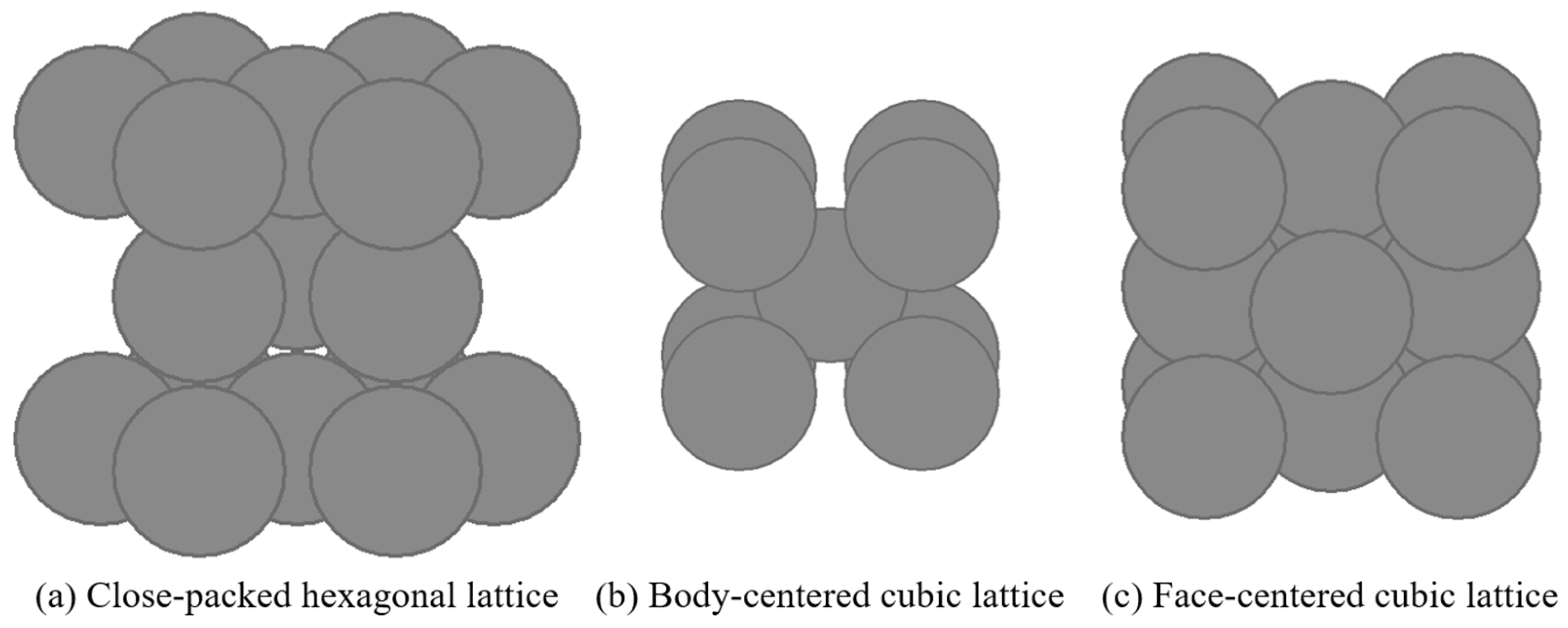
Figure 1 shows the crystal structures of each substrate metal. Ti, Fe, and Ni are close-packed hexagonal (hcp), body-centered cubic (bcc), and face-centered cubic (fcc), respectively.
Table 1 shows the lattice parameters of each crystal structure and the atomic radius of sodium used for calculation. [
22] The interfaces for the theoretical calculations are the close-packed planes of the respective crystal structures: (0001) for Ti, (110) for Fe, and (111) for Ni.
The depth profile of implanted atoms depends largely on the implantation energy, the implantation dose, and the type of implantation atom and substrate material. The depth profile of implanted atoms can be predicted with the linear-solvent-strength theory using these implanted conditions. [
23] However, the exact location of the implanted atoms in the crystal structure is unknown. Therefore, in the calculation model, the implanted atoms were replaced with substrate metal atoms on the topmost surface and the surface below.
Subsequently, two sodium atoms were placed above and below the on-top site of the substrate metal surface to represent the interface with liquid sodium. Theoretical calculations of the interface confirmed no significant change in the atomic interaction at the interface between the on-top and hollow sites of the metal substrate. [
2] Therefore, this study performs the calculations at the on-top site.
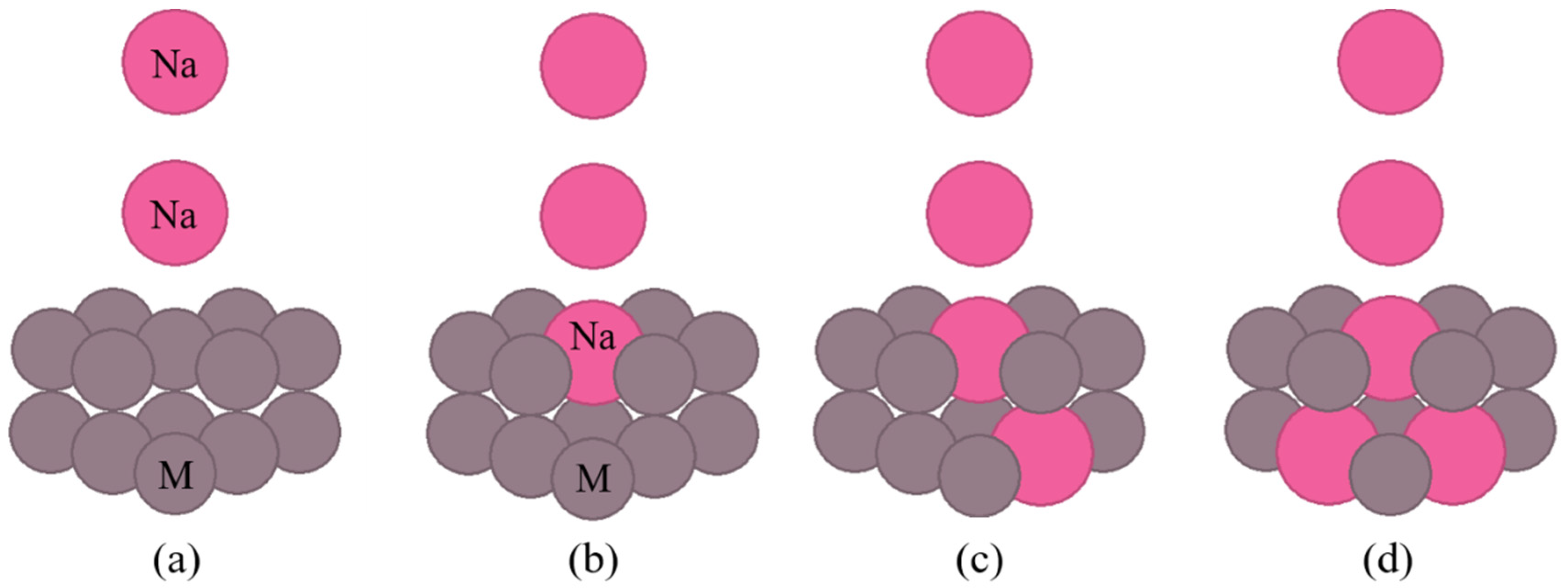
Figure 2 and
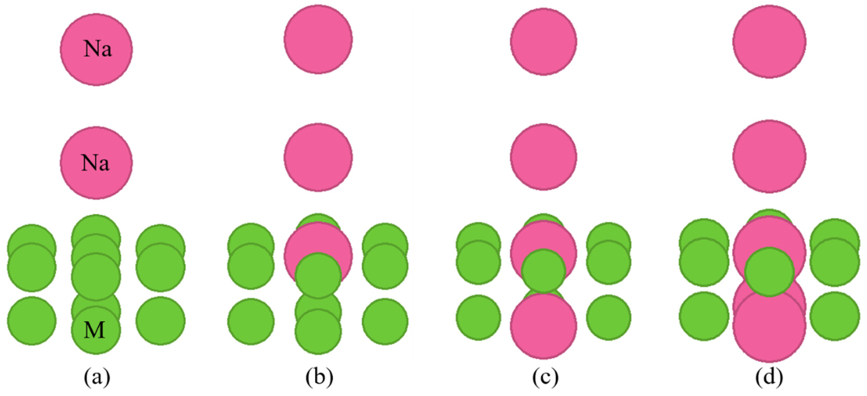
Figure 3 show the cluster models of the interface used in the calculations.
Figure 2 shows the cluster models when the crystal structure of the substrate metal is hcp or fcc lattices, and Fig. 3 shows the cluster models when the crystal structure of the substrate metal is a bcc lattice. In these figures, M means the substrate metal atom. Figure (a) shows the no implantation cluster model. The sodium atom in the on-top of the surface is in contact with the atoms directly below. The sodium atoms are also in contact with each other. Figures (b)–(d) show the cluster model with sodium implantation. They presume the implantation of one, two, and three sodium atoms, respectively.
3. Theoretical calculation results
3.1. Density of states
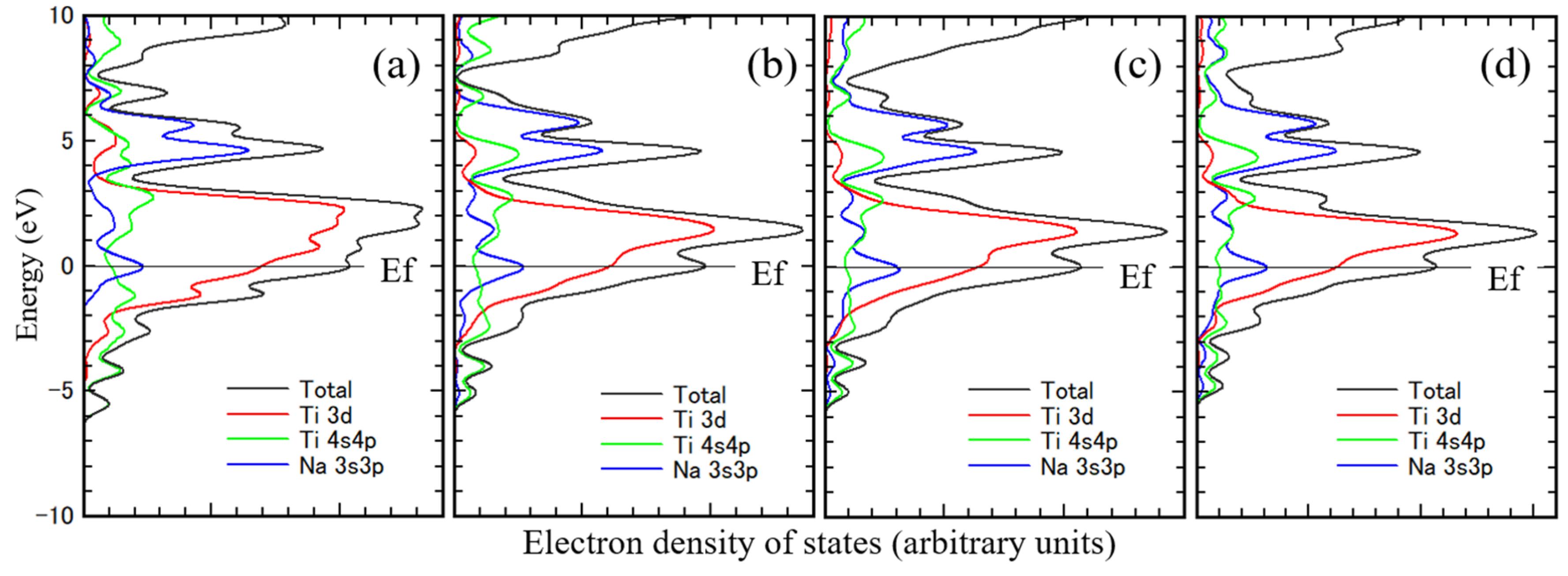
Figure 4 shows the density of states of Ti obtained from the theoretical calculations. Figure (a) is for unimplanted Ti, and
Figures (b)–(d) are for sodium-implanted Ti. The
Ef in the figures indicates the Fermi level. From these figures, the 3d orbital component of Ti is near the Fermi level, and its peak is above the Fermi level, indicating that the 3d orbital is yet to be occupied with electrons. The 4sp orbital component of Ti is above the Fermi level, the typical density of states for Ti, and it correlates well with the band calculation results. [
24,
25,
26] The electronic state of Ti is well represented, even in a small cluster model with 13 Ti atoms. The peak of the 3d orbital component of Ti approaches the Fermi level due to sodium implantation because of the charge transfer from sodium to Ti. The electronegativity of sodium is smaller than that of Ti, and the atomic radius of sodium is larger than that of Ti. Hence, the charge transfer occurred to Ti from sodium. The 3sp orbital sodium component on the Ti substrate is above the Fermi level in the near 5 eV region.
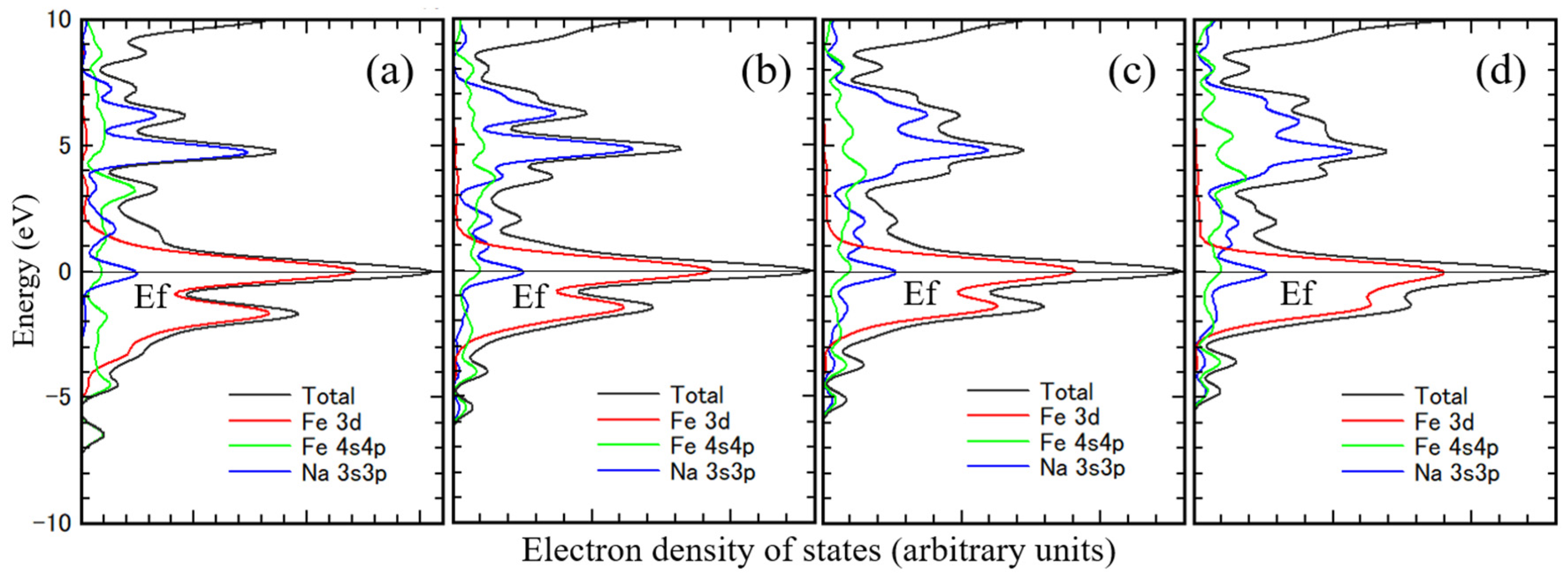
Figure 5 shows the density of states of Fe. The peak of the 3d orbital Fe component is at the Fermi level at all density of states. Only half of the electrons are occupied in the 3d orbital of Fe. The 4sp orbital Fe component is primarily above the Fermi level, the typical density of states for Fe, correlating well with the band calculation results. [
27,
28,
29,
30] Figure (a) is for unimplanted Fe, and
Figures (b)–(d) are for sodium-implanted Fe. The 3d orbital Fe components under the Fermi level increase with increasing the amount of implanted sodium. The charge transfer to Fe from sodium also occurred. The 3sp orbital sodium component is mostly in the 5 eV region above the Fermi level.
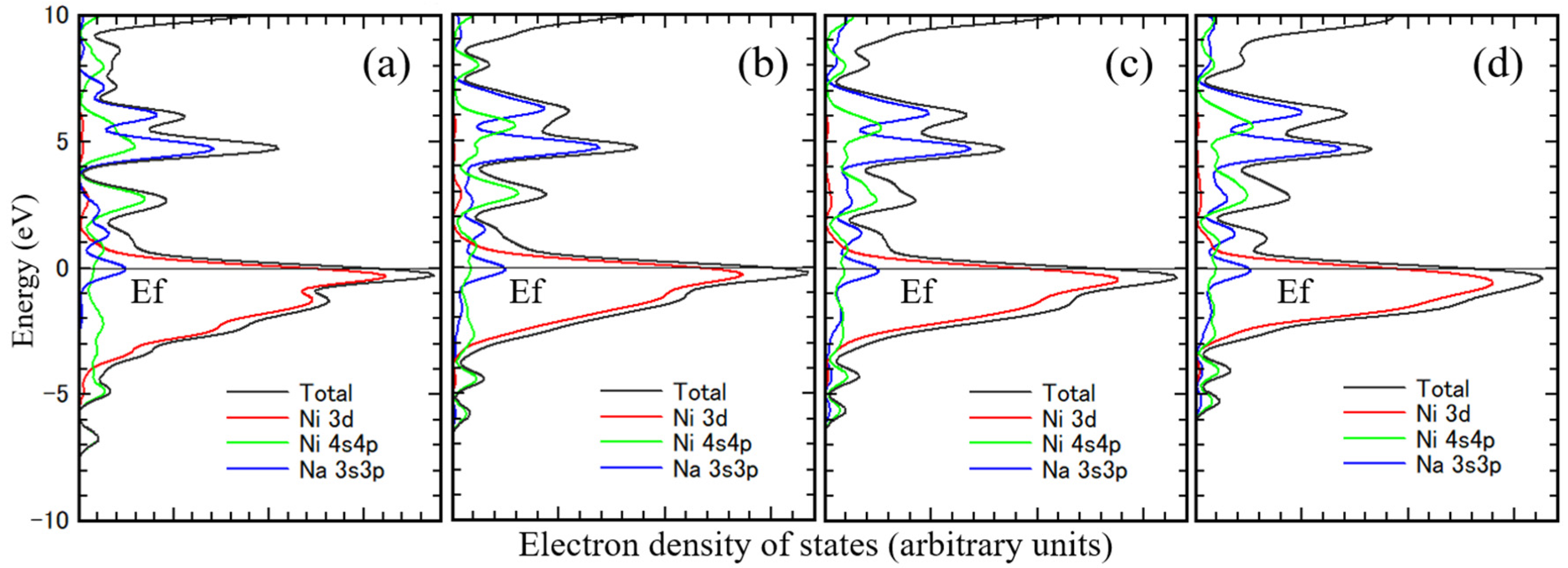
Figure 6 shows the density of states of Ni. The 3d orbital Ni component is almost under the Fermi level in all figures. The 3d orbitals of Ni are mostly occupied electrons. Ni 4sp orbitals are primarily above the Fermi level, the typical density of states for Ni, correlating well with the band calculation results. [
28,
31,
32] Figure (a) is for unimplanted Ni, and Figures (b)–(d) are for sodium-implanted. The 3d orbital Ni components under the Fermi level increase with the amount of implanted sodium because of the charge transfer from sodium to Ni. The 3sp orbital sodium component is mostly in the 5 eV region above the Fermi level.
The density of states is characteristic of the 3d orbital component of the substrate metal and the 3sp orbital component of sodium. And the 3d orbital component of substrate metal shifted to deeper energy level with increasing their atomic number. Even this small cluster model sufficiently represents the electronic state of the interface.
3.2. Electron density maps
Figure 7,
Figure 8 and
Figure 9 show the electron densities maps at the (112 ̅0), (110), and (110) for Ti, Fe, and Ni, respectively. Figure (a) is for the unimplanted metal, and Figures (b)–(d) is for the sodium-implanted metal.
In
Figure 7, the electron density between the Ti atoms (region A) decreases due to sodium implantation, indicating that sodium implantation weakens the atomic bonds within Ti. However, the electron density between the sodium atoms (region B) remains almost unchanged, indicating that sodium implantation hardly changes the bonding with sodium at the interface.
In
Figure 8, the electron density between the Fe atoms (region C) decreases due to sodium implantation, indicating that sodium implantation weakens the atomic bonds within Fe. However, the electron density between the sodium atoms (region D) increases. In other words, sodium implantation strengthens the bonding with sodium at the interface.
In
Figure 9, the electron density between the Ni atoms (region E) decreases due to sodium implantation, indicating that sodium implantation weakens the atomic bonds within Ni. However, the electron density between the sodium atoms (region F) remains almost unchanged. In other words, as with Ni, sodium implantation hardly changes the bonding with sodium at the interface.
The electron density changes within the substrate metal and at the interface due to sodium implantation, depending on the substrate metal. These differences might be related to differences in wettability with liquid sodium. Peter et al. proposed that in water–metal wetting, changes in the electron density at the interface are related to wettability. [33] The same might be true if the liquid is not water but a liquid metal.
3.3. Atomic bonding at interface
The change in atomic bonding within the substrate metal and at the interface, which affects wettability due to sodium implantation, is described.
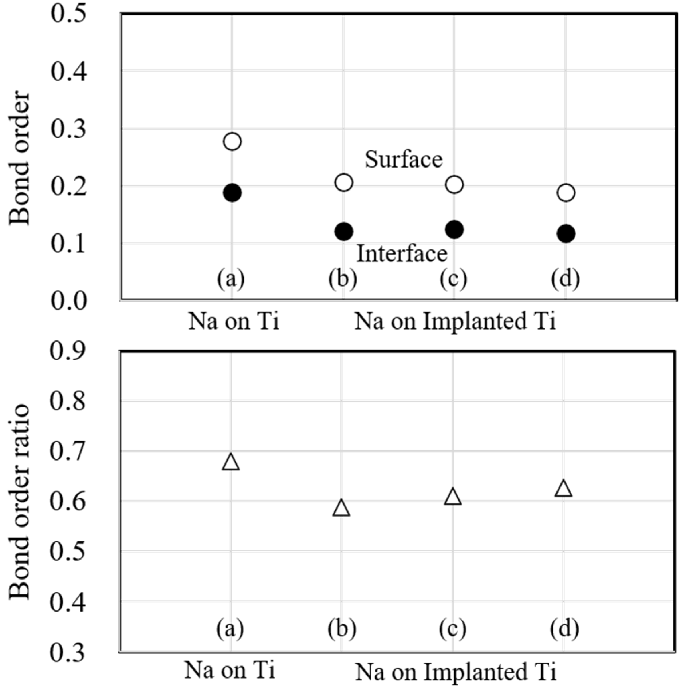
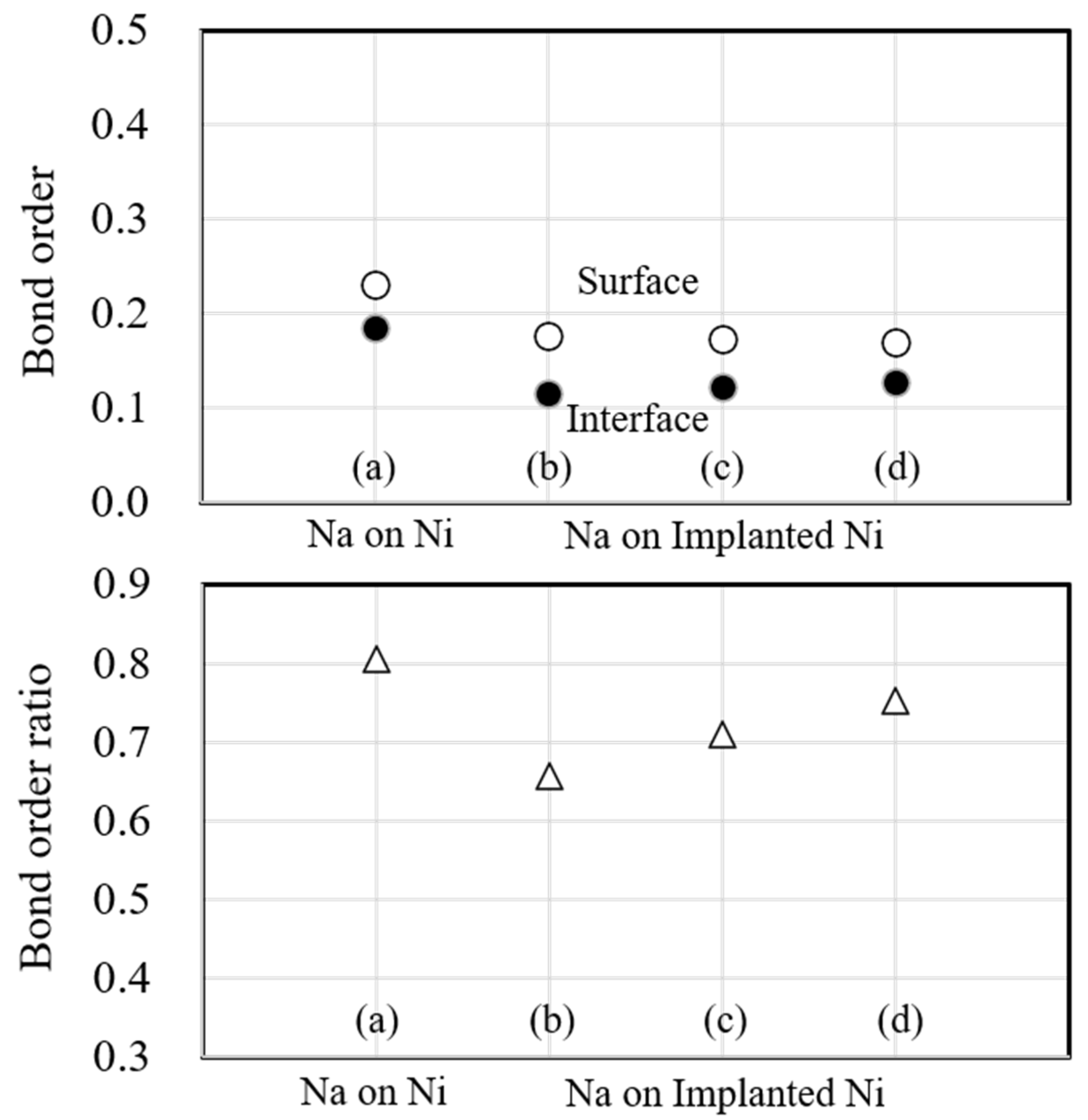
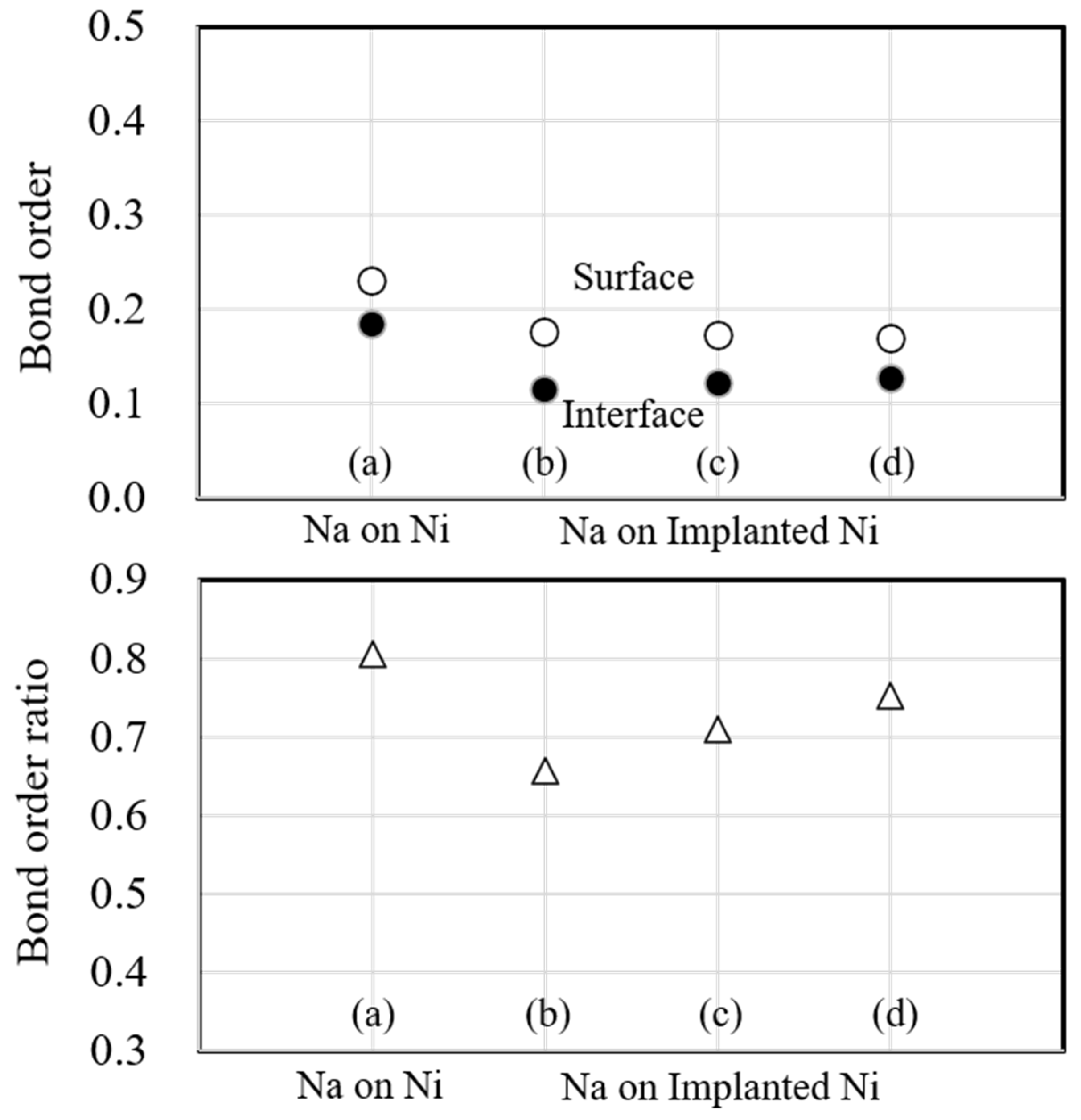
Figure 10 shows the bond order and bond order ratio when the substrate metal is Ti. Surface (○) is the bond order within the substrate metal, and interface (●) is the bond order at the interface between the substrate metal and the sodium atoms on the surface. In this figure, the atomic bonding of the surface decreased due to sodium implantation and further decreased with increasing implantation. However, the atomic bonding of the interface decreased due to sodium implantation but did not change significantly with increasing implantation, consistent with the electron density in Fig. 7. Next, the bond order ratio is that of the bond order between the surface and the interface. It decreases due to sodium implantation compared to the unimplanted one. However, it increases when the implanted sodium atoms increase, indicating that the atomic bonding at the interface is stronger than that within the substrate metal due to the increasing sodium implantation.
Figure 11 shows the bond order and bond order ratio when the substrate metal is Fe. In these figures, the atomic bonding of the surface decreased due to sodium implantation, and it decreased slightly with the increasing implantation. However, the atomic bonding of the interface also decreased due to sodium implantation but noticeably increased with increasing implantation. This change is consistent with the electron density in Fig. 8. Next, the bond order ratio of Fe is significantly smaller than that of Ti. As in Ti, the bond order ratio decreases with sodium implantation but is larger when the implanted sodium atoms are increased compared to the unimplanted one. This result indicates that the atomic bonding at the interface is stronger than within the substrate metal due to the increasing sodium implantation.
Figure 12 shows the bond order and bond order ratio when the substrate metal is Ni. In these figures, the atomic bonding of the surface decreased due to sodium implantation, and it decreased further with the increasing implantation. However, the atomic bonding of the interface decreased due to sodium implantation but noticeably increased when the implanted sodium atoms were increased. The change is consistent with the electron density in Fig. 9. Next, the bond order ratio for Ni is the largest among Ti and Fe. As in Ti, the bond order ratio decreases with sodium implantation but is larger when the implanted sodium atom is increased compared to the unimplanted one. This result indicates that the atomic bonding at the interface is stronger than that within the substrate metal due to the increasing sodium implantation.
4. Discussion
4.1. Wettability with liquid sodium of sodium-implanted substrate metal
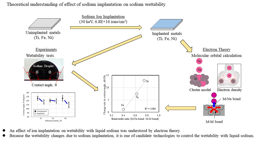
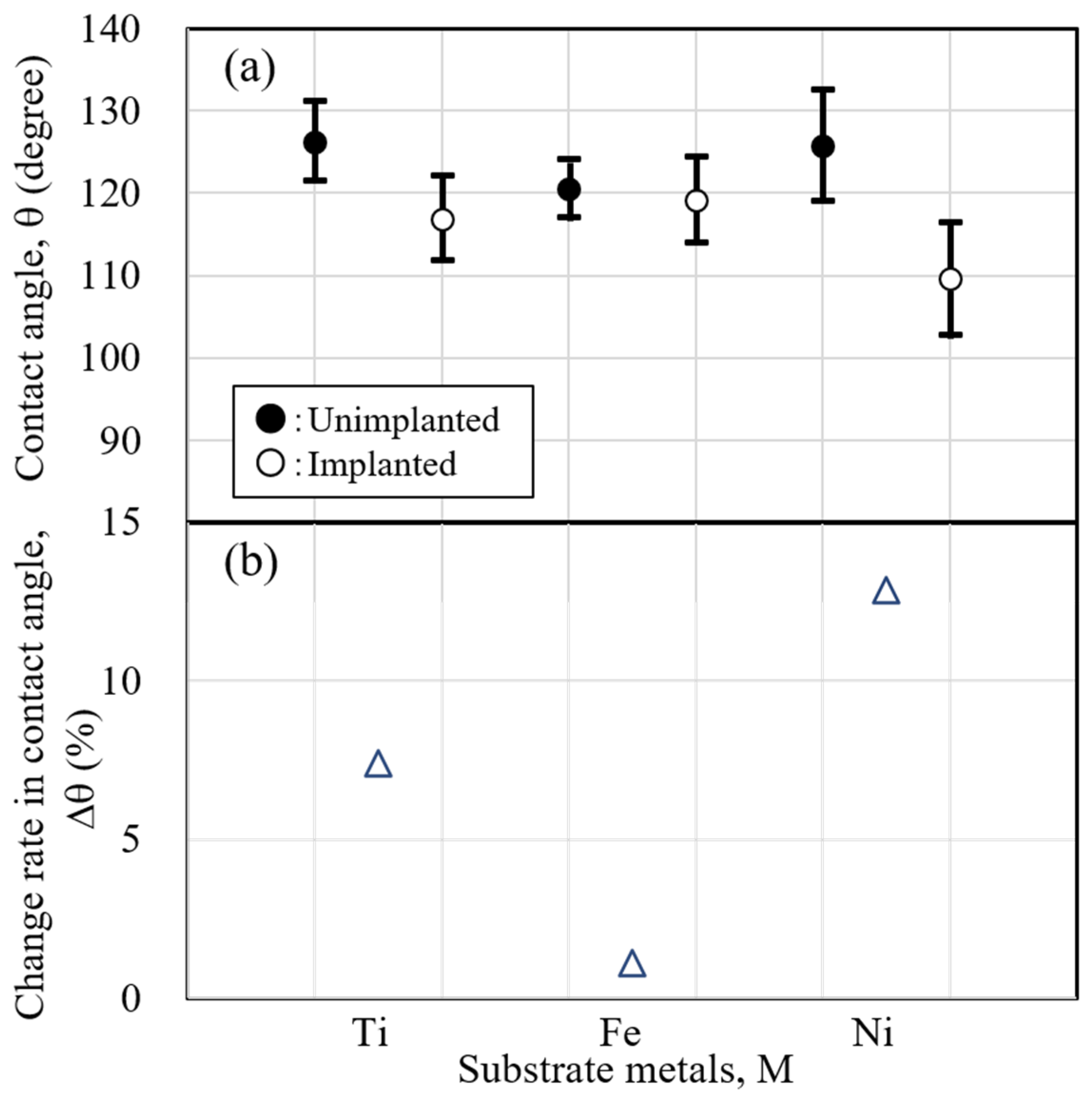
The wettability of the sodium-implanted metal was evaluated to discuss the results of the theoretical calculations of the interface due to sodium implantation. Sodium implantation was performed on Ti, Fe, and Ni substrate metals at an implantation energy of 30 keV and an implantation dose of 6.8 E + 16 ions/cm
2. The conditions of wettability experiment were 389 K of liquid sodium and substrate metal and 0.1 mL of liquid sodium droplet volume. The wettability was evaluated using the contact angle between the substrate metal and liquid sodium droplet.
Figure 13(a) shows the results of the contact angle, , and
Figure 13(b) shows the change rate in the contact angle, . The change rate in the contact angle, Dq, from the unimplanted substrate metal was calculated using the following equation (1).
Dq: Change rate in contact angle (%)
qUnimplanted : Contact angle of unimplanted substrate metal (degree)
qImplanted : Contact angle of implanted substrate metal (degree)
This formula was chosen because the smaller the contact angle, the better the wettability. A positive value in this equation indicates good wettability.
The contact angle results, which indicate wettability, show that for all substrate metals, the contact angle decreases, and the wettability improves due to sodium implantation. However, the amount of change in contact angle varies depending on the kind of substrate metal. The change in wettability was in the order of Ni > Ti > Fe.
4.2. Relationship between the atomic interaction at the interface and contact angle
In our previous studies, we discussed contact angles in terms of bond order ratios. This study focuses on the change in the contact angle due to sodium implantation and discusses it using bond order ratios.
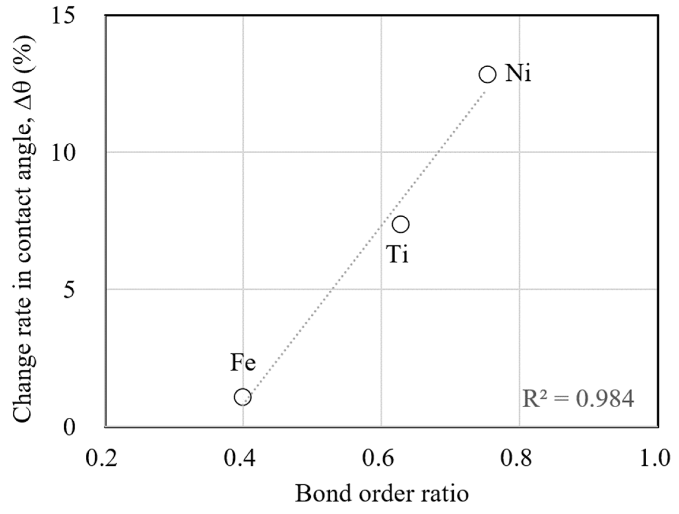
Figure 14 shows the relationship between the bond order ratio and the change rate in contact angles. The values of bond order ratios are used for those for case (d) with a high dose of sodium implantation. This figure shows that the larger the bond order ratio, the larger the change rate in the contact angle due to sodium implantation. Since the bond order ratio is the ratio of the atomic bonding in the substrate metal to that at the interface, a larger value indicates a stronger bonding with liquid sodium at the interface. In other words, this figure shows that the change in the contact angle is larger when the atomic bonding with liquid sodium at the interface becomes stronger due to sodium implantation. The change in wettability due to sodium implantation can be explained consistently through theoretical atomic interactions.
5. Conclusions
This study focused on the ion implantation technique to change the electronic state at the interface and aimed to understand the change in the electronic state at the interface of sodium implantation of the substrate metal. Furthermore, the wettability experiments of sodium implantation on the substrate metal are discussed based on the atomic interaction, which results from calculating the electronic state. The following results were obtained.
- (1)
The atomic bonding in substrate metal weakens due to sodium implantation. The atomic bonding also weakens with increasing sodium atom implantation.
- (2)
The atomic bonding between the substrate metal and the sodium at the interface changed. The change was almost negligible for Ti but became stronger for Fe and Ni with increasing sodium atom implantation.
- (3)
The bond order ratio which is the ratio between bond order in the substrate metal and that between sodium and substrate metal increases with increasing sodium atom implantation.
- (4)
The change rate of the contact angle, which indicates wettability, due to sodium implantation in relation to the bond order ratio was larger when the bond order ratio was larger. This result indicates that the change in the contact angle is greater when bonding at the interface becomes stronger, consistent with theory.
This study understood the change in the electronic state of the substrate metal due to sodium implantation. The change in the contact angle, which is an indicator of wettability, can be understood theoretically from the change in the electronic state of the interface. It was clarified that the electronic state of the interface affects the wettability of liquid sodium.
Author Contributions
Jun-ichi Saito: Project administration, Conceptualization, Experiments, Visualization, Writing – original draft. Hideo Shibutani and Yohei Kobayashi: Conceptualization, Discussion, Masanari Namie and Asuka Ikeda: Experiments, Data validation. All authors have read and agreed to the published version of the manuscript.
Funding
This research received no external funding.
Institutional Review Board Statement
Not applicable.
Informed Consent Statement
Not applicable.
Data Availability Statement
The data related to this study are all presented in the article.
Conflicts of Interest
The authors declare no conflicts of interest.
References
- Saito, J.; Shibutani, H.; Kobayashi, Y. ; Fundamental Study on Wettability of Pure Metal by Liquid Sodium, The Minerals, Metals & Materials Society 2020, J. Li et al. (eds.), Characterization of Minerals, Metals, and Materials 2020, The Minerals, Metals & Materials Series 2020, The Minerals, Metals & Materials Series. [CrossRef]
- Saito, J.; Kobayashi, Y.; Shibutani, H. , Wettability of Pure Metals with Liquid Sodium and Liquid Tin, Materials Transactions, Vol. 62, No. 10 (2021) pp. 1524 to 1532. [CrossRef]
- Saito, J.; Kobayashi, Y.; Shibutani, H. , Fundamental Study on Wettability of Pure Metal Using a Low Melting Temperature Alloy: A Theoretical Approach, The Minerals, Metals & Materials Society 2022, M. Zhang et al. (eds.), Characterization of Minerals, Metals, and Materials 2022, The Minerals, Metals & Materials Series. [CrossRef]
- Saito, J.; Monbernier, M. , Relationship between the contact angle of pure Cu and its alloys owing to liquid Na and electronic states at the interface, Surfaces and Interfaces 41 (2023) 103248. [CrossRef]
- Mayer, J.M.; Erikson, L.; Davies, J.A. , Ion Implantation in Semiconductors, Academic Press, New York (1970), NSA-24-049253.
- Wilson, R.G.; Brewer, G.R. ; Ion Beams with Application to Ion Implantation, John Wiley and Sons, New York (1973), ISBN-13: 978-0471950004.
- Dearnaley, G.; Freeman, J.H.; Nelson, R.S.; Stephen, J. ; Ion Implantation, North-Holland Pub. Co., Amsterdam (1973), ISBN-13 978-0720417586.
- Hirvonen, J.K. , Ion Implantation, in Treatise on Material Science and Technology (18), Academic Press, New York (1980), ISBN 0123418186.
- Preece, C.M.; Hirvonen, J.K. , Ion Implantation Metallurgy, The Metallurgical Soc. Of AIME, Warrendale Pa. 1979; ISBN 9780895203649, 0895203642. [Google Scholar]
- Saito, J.; Hayashi, K.; Kano, S.; Kasai, N.; Seguchi, T. , Development of New Surface Modified Materials by Ion Implantation, JAERI TIARA Annual Report 1995 (VOL.5) APRIL 1995 – MARCH 1996, JAERI-Review 96-017:138-140. [CrossRef]
- Hayashi, K.; Saito, J.; Kano, K.; Kasai, N.; Kudo, H. , Seguchi, T., Changes in microstructure and surface properties of metals by ion implantation, TIARA Annual Report 1996, 1997, JAERI-Review 97-015:139-141. [CrossRef]
- Saito, J.; Hayashi, K.; Kano, S.; Kasai, N.; Kudo, H.; Morita, Y. , Surface Modification of Corrosion Resistant Materials by Ion Implantation, TIARA Annual Report 1997, 1998, JAERI-Review 98-016:164-166. [CrossRef]
- Chen, X.; Yin, X.; Jin, J. , A Study on the Wettability of Ion-Implanted Stainless and Bearing Steels, Metals 2019, 9(2), 208. [CrossRef]
- Rimondini, L.; Farè, S.; Chiesa, R.; Pedeferri, M.P.; Carrassi, A. The effect of composition, wettability and roughness of the substrate on in vivo early bacterial colonization of titanium. Journal of Applied Biomaterials & Biomechanics 2003, 1, 131–138. [Google Scholar]
- Suzuki, Y.; Kusakabe, M.; Iwaki, M. , Wettability control of polystyrene by ion implantation, Nuclear Instruments and Methods in Physics Research, 1994, B91(1-4): 584-587. [CrossRef]
- Suzuki, Y.; Kusakabe, M.; Iwaki, M. , Surface modification of polystyrene for improving wettability by ion implantation, Nuclear Instruments and Methods in Physics Research B, 1993 80/81: 1067-1071. [CrossRef]
- Fu, R.K.Y.; Cheung, I.T.L.; Mei, Y.F.; Shek, C.H.; Siu, G.G. ; Chu, Paul K.; Yang, W.M.; Leng, Y.X.; Huang, Y.X.; Tian, X.B.; Yang, S.Q., Surface modification of polymeric materials by plasma immersion ion implantation, Nuclear Instruments and Methods in Physics Research B, 2005, 237: 417-421. [CrossRef]
- Jeon, J.; Choi, D.; Kim, H.; Park, Y.T.; Choi, M.-J.; Chung, K.-B. , Wettability Conversion of an Aluminum-hydroxide Nanostructure by Ion Implantation, Journal of the Korean Physical Society, 2016, 68(8): 1024∼1028. [CrossRef]
- Adachi, H.; Tsukada, M.; Satoko, C. , Discrete Variational X Cluster Calculations. I. Application to Metal Cluster, J. Phys. Soc. Jpn, 45 (1978) 875-883. [CrossRef]
- Satoko, C.; Tsukada, M.; Adachi, H. , Discrete Variational X Cluster Calculations. II. Application to the Surface Electronic Structure of MgO, J. Phys. Soc. Jpn, 45 (1978) 1333-1340. [CrossRef]
- Adachi, H.; Shiokawa, S.; Tsukada, M.; Satoko, C.; Sugano, S. , Discrete Variational X Cluster Calculations. III. Application to Transition Metal Complexes, J. Phys. Soc. Jpn, 47 (1979) 1528-1537. [CrossRef]
- The Japan Institute of Metals: Kinzoku Data Book (2004) pp. 36-40, ISBN 978-4-621-07367-4.
- Lindhard, J.; Scharff, M.; Schiott, H.F. , Range concepts and heavy ion ranges. (Notes on atomic collisions, II.), K. Dan. Vidensk. Selsk. Mat-Fys. Medd., 33, 14 (1963). [CrossRef]
- P. Hądzel, P.; T. Radoń, T.;, Lee, M.J.G.; Chow, J.C.L., Surface density of states on the (0001) face of titanium, Surface Science, Vo. 442, Issue 1 (1999) pp. 36-46. [CrossRef]
- Jafari, M.; Bayati, K.; Jahandoost, A.; Zarifi, N.; Nobakhti, M.; Jamnezhad, H. , Role of s and d-electrons in Density of State of Titanium in high pressure, J. Physics: Conference Series 215 (2010) 012108. [CrossRef]
- Cornwell, J.F. , Hum, D.M.; Wong K.G., Density of states in iron, Physics Letters A, Volume 26, Issue 8, Pages 365-366. [CrossRef]
- Spicer,W.E, Cu, Ni, Ag, and Fe Densities of States, J. Appl. Phys. 37, 947–952 (1966). [CrossRef]
- Weiss, R. J.; Mazzone, G. , The electronic structure of the 3d transition metals, J. Appl. Crystallography, Vol. 14, Issue6, (1981), pp. 401-416. [CrossRef]
- Callaway, J.; Wang, C. S. , Energy bands in ferromagnetic iron, Phys. Rev. B 16, 2095 (1977). [CrossRef]
- Blodgett Jr., A. J.; Spicer W. E., Density of States in Nickel, Phys. Rev. Lett. 15, 29 – Published. [CrossRef]
- Fletcher, G. C. , Density of States Curve for the 3d Electrons in Nickel, Proceedings of the Physical Society. Section A, Volume 65, Number 3 1952 Proc. Phys. Soc. A 65 192. [CrossRef]
- Somlyai-Sipos, L.; Baumli, P. , Wettability of metals by Water, Metals 12 1274 (2022). [CrossRef]
|
Disclaimer/Publisher’s Note: The statements, opinions and data contained in all publications are solely those of the individual author(s) and contributor(s) and not of MDPI and/or the editor(s). MDPI and/or the editor(s) disclaim responsibility for any injury to people or property resulting from any ideas, methods, instructions or products referred to in the content. |
© 2024 by the authors. Licensee MDPI, Basel, Switzerland. This article is an open access article distributed under the terms and conditions of the Creative Commons Attribution (CC BY) license (http://creativecommons.org/licenses/by/4.0/).
