1. Introduction
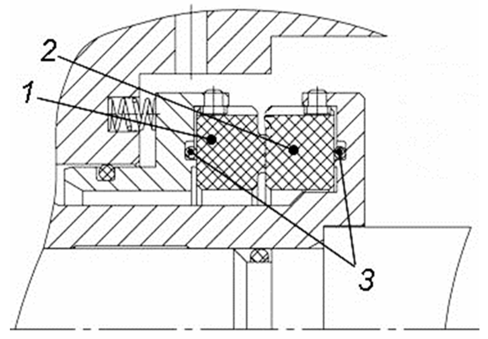
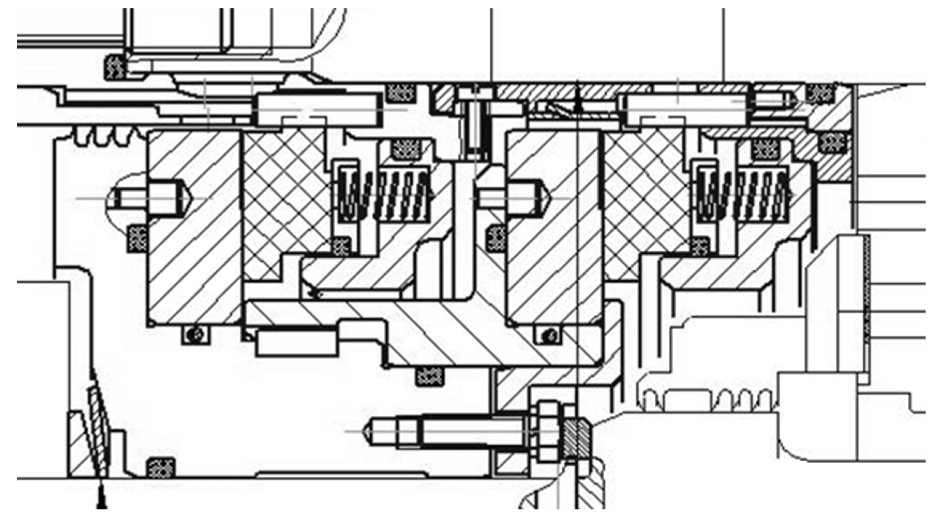
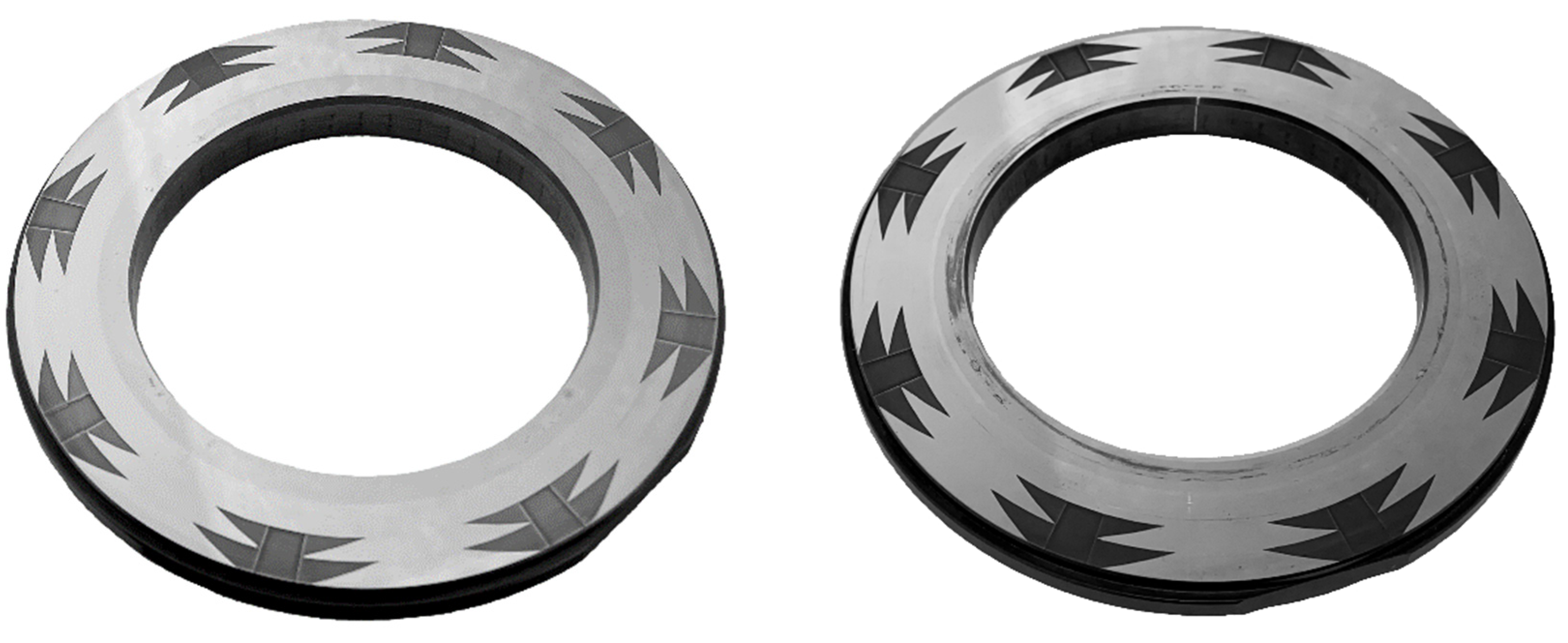
In the design of various mechanical seals (
Figure 1), it is critically important to take into account axial forces balance, bending moments balance, and thermal balance of the sealing rings. Axial force balance determines the nominal sealing gap, which in turn affects seal leakage and friction power. The roughness parameters of the sealing faces must be taking into account. Bending moments balance is particularly critical for seals operating under high pressure drops and those employing the graphite sealing ring, given graphite’s relatively low Young’s modulus (9-17 GPa). If the bending moment balance is ensured, the sealing ring faces are either be plane-parallel or have a certain angular distortion. Considering thermal balance is necessary for seals operating under the high pressure drops (more than 10 MPa) and high rotational speed (more than 15 000 RPM) in turbomachines, as well as when significant temperature drop (more than 100 K) is present.
The dynamic analysis of seal performance is necessary during the design process of turbomachinery rotor seals, as well as for investigating emergency stoppages in turbomachineries caused by the loss of seal tightness [
1]. One of the most common causes of seal failure is increased rotor vibration [
2]. Bo Ruan demonstrated the importance of dynamic investigation of a dry gas seal to determine whether the stator ring can track the displacement of rotor axial vibrations, using the small perturbation method [
3]. Green and Varney investigated the effect of stator and rotor ring impact on the dynamic performance of a dry gas seal to predict seal failures resulting from rotor axial vibrations [
4]. Traditionally, computational analysis of seal dynamics is conducted, followed by frequency tuning if required. This tuning involves adjusting the mass of the seal rings, the stiffness of elastomer O-rings, or the stiffness of the fluid film (lubricating film) in the sealing gap. If the issue does not have a direct and clear solution, it becomes necessary to provide the required damping of the fluid film in the seal gap. In such cases, two problems - the computational fluid dynamics analysis of the fluid flow in the gap and the motion of the seal rings - are involved in determining the dynamic performance of the seal. These two problems must be considered together.
Most of the research dedicated to sealing technology, especially dry gas seals, focuses on the gas-dynamic calculation of the fluid flow in the seal gap (lubricating film). These analyses aim to determine the pressure distribution in the gap and the leakage mass flow rate, which depend on the geometric parameters of the seal rings and face grooves. Methods based on the solution of the Reynolds equation are used to solve this problem [
5]. In the absence of external perturbations to the fluid flow in the seal gap, laminar flow is established [
6]. A more accurate solution of this problem is achieved by direct solutions of the Navier-Stokes equation or the Reynolds-averaged Navier-Stokes equation using turbulence models [
7,
8]. In addition, consideration of the heat transfer between the fluid in the gap and the seal rings has a significant effect on the pressure distribution and leakage rate [
9,
10].
The problem of seal ring motion, or seal dynamics, comes down to the correct choice of the appropriate seal dynamic model. Typically, a simplified single-mass dynamic model is used to describe the motion of the stator seal ring. The focus is on determining the dynamic performances of a thin fluid film in a non-contact mechanical seal. The fluid film in the seal gap can be simply represented in the form of stiffness and damping, which for liquids are determined by the viscosity and geometric parameters of the seal rings [
11,
12], and for gases also depend on the vibration frequency and amplitude [
13,
14].
Traditionally, the small perturbation method is used to solve dynamic problems. This method can be used to obtain analytical solutions with acceptable simplifications. Thus, the influence of the geometrical parameters of the seal on its performances can be determined relatively easily and in a short time [
15,
16,
17,
18,
19,
20]. In particular, this method has been used to explain the operation of a mechanical dry gas seal with a gap value of 2 µm, even in the presence of axial rotor vibrations with frequencies up to 100 Hz and amplitudes up to 0.3 mm [
13]. To reduce computation time and increase accuracy in solving dynamic problems, Miller and Green proposed the step jump method and the direct numerical frequency response method [
21]. The accuracy of the dynamic performances determination of the fluid film in the seal gap can also be improved by taking into account the deformation influence of the seal ring faces, and by considering the problem of fluid flow in the seal gap using transient analysis [
22,
23]. Especially important is thermal deformation, since the deformation of the sealing ring is mainly caused by the influence of temperature [
24]. A further accuracy improvement of the dynamic performances of the fluid film in the seal gap is achieved by taking into account the influence of roughness, texturing and groove manufacturing methods of the seal ring faces [
25,
26].
The cited papers do not cover the whole range of existing seal designs and therefore and do not allow to solve the problem of reliable operation of seals in the presence of a complex spectrum of rotor vibration loads. This limitation arises from the reliance on a single-mass dynamic model of the seal. In addition, published research works have focused mainly on small changes in the seal gap compared to the nominal equilibrium gap value. For large values of oscillation amplitude and frequency (amplitude greater than 25 µm and frequency greater than 150 Hz) it is necessary to take into account the squeezing of the gas film in the seal gap [
4,
27]. Recently, research has been published on the numerical determination of stiffness and damping in a mechanical seal in the presence of large amplitudes and frequencies of axial rotor vibrations [
18,
20,
28]. However, these works still use a single-mass dynamic model of the seal.
Therefore, to analyse the dynamics performances of the dry gas and hydrodynamic seals, both the joint solution of the computational fluid dynamics problem and the application of more complex dynamic models are required.
The aim of the this research work is to develop recommendations for the application of existing dynamic models and those developed by the authors for various types of mechanical seals for turbomachinery applications, for specific operating conditions and designs.
2. Single-Mass Dynamic Model of Mechanical Contact Seal
2.1. Model Description
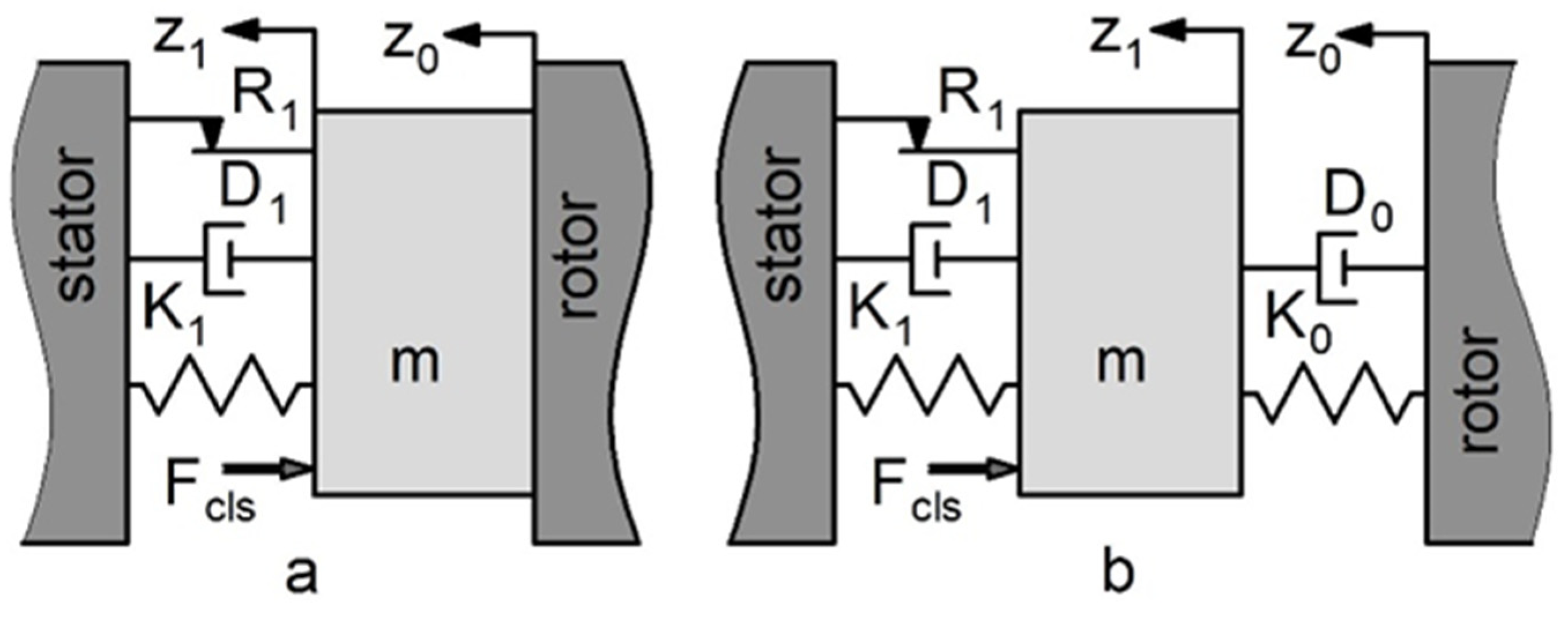
The dynamic model of a mechanical contact seal, unlike a lubricated seal, has a displacement limiter - the face of the rotor ring. The dynamic model of the mechanical contact seal for the two operation modes (nominal contact and separation modes) is shown in
Figure 2. K
1 – is a spring stiffness, R
1 – is a friction force and D
1 – is a damping of the elastomer O-ring. K
0 and D
0 – are the stiffness and damping of the fluid flow in the seal gap (in the case of separation operation mode). The stator seal ring with mass m is pressed against the face of the rotor seal ring by the differential pressure of the fluid (force F
cls) and springs force. For nominal contact operation mode the displacements of the rotor seal ring and the stator seal ring are identical z
0=z
1.
The stator seal ring will separate from the face of the rotor seal ring when the axial acceleration of the rotor is greater than the “contact force” acceleration, which is the ration of the unbalanced axial contact force to the mass of the seal ring (m). The boundary conditions of the seal separation mode can be determined. While the stator seal ring separation mode can be prevented by limiting the frequency (ω) and amplitude (z
0amp) of the axial rotor vibration. In order to describe the axial motion of the separated stator seal ring it is necessary to determine the stiffness dependence of the fluid in the seal gap on the gap value (h). It must also be taken into account that the frictional force of the elastomer O-ring changes sign during movement. There are two possible solutions. If z
1 < 0 while 0.5‧π‧ω < t < 1.5‧π‧ω, then non-stop movement of the stator seal ring is realised. t – is time. If z
1 > 0, the seal ring has a stop when the axial displacement of the rotor equals its amplitude value (z
0 = z
0amp). The stopping time depends on the value of 2‧R
1/(K
1+K
0). The separation of the stator seal ring ends when z
1 and z
0 are equal again (z
1 = z
0). The seal then operates normally with the contact. Motion equation of the stator ring for two operation modes:
where
is signum function of
:
The stator seal ring separation is undesirable operation mode. It is necessary to determine the boundary conditions to prevent this operation mode by limiting the axial vibration frequency. The frequency value must be lower than the value below:
where
– is the natural frequency of the seal for the contact operation mode.
It should be noted that if the rotor vibration frequency significantly exceeds the natural frequency of the seal during separation operation mode, the separation process will stop [
26].
If the frequency ω does not exceed ω
max, there is another possible case of stator ring separation. The separation happens when the stator seal ring is in a state of suspension:
The properties of elastomer O-rings have a significant influence on the performance of all types of mechanical seals. Their parameters must be taken into account: geometric parameters such as cross-sectional diameter and outer diameter, frictional force, stiffness and damping. With high contact pressures of the rubber O-ring against the metal surface and small displacement of the stator seal ring, there is little or no slippage in the O-ring. The axial movement of the stator seal ring in this case is mainly due to the elasticity of the O-ring. This leads to changes in the seal’s load carrying capacity and therefore changes in its dynamic behaviour.
For example: there is a dimension by which the outer diameter of mechanical seal rings must be changed. In this case it is also necessary to change «inwards» the O-ring the contact diameter of the elastomer O-ring with the metal surface. In the conventional design (sliding contact on the outer surface of the O-ring like in
Figure 1), the radial contact displacement for an O-ring with a hardness of 90 (Shore A hardness scale) is approximately 5% of the O-ring cross-sectional diameter at low pressure drop. As the pressure drop increases, the radial contact displacement decreases to 2% at a pressure drop of 10 MPa. If the sliding contact is on the inner surface of the O-ring, the radial displacement of the contact is «inwards» the O-ring and is 2 times greater. In this case, the frictional force of the O-ring might not be considered in the calculation.
It should be noted that there are few publications that focus on the determination of O-ring stiffness and damping under dynamic loading. For estimation calculations, it is possible to use the results obtained by Green and Etsion [
29]. The mass of the elastic parts (such as springs or bellows) is taken into account by increasing the mass of the stator seal by 1/3 of the mass of these parts.
3.2. Calculation Results and Discussion
The phenomena of the stator ring separation from the rotor ring in mechanical seal is encountered in practice by a number of companies. The mechanical contact seal of the compressor was analysed (
Table 1). This seal had sealing problems when the rotor speed was in the range of 725 to 880 rad/s.
In the compressor, due to its design, pressure oscillations occurred in the pressurised cavity, causing rotor axial vibrations at a frequency 3-4 times the rotor operating frequency. It was found that the seal had operational problems at excessive rotor axial vibrations.
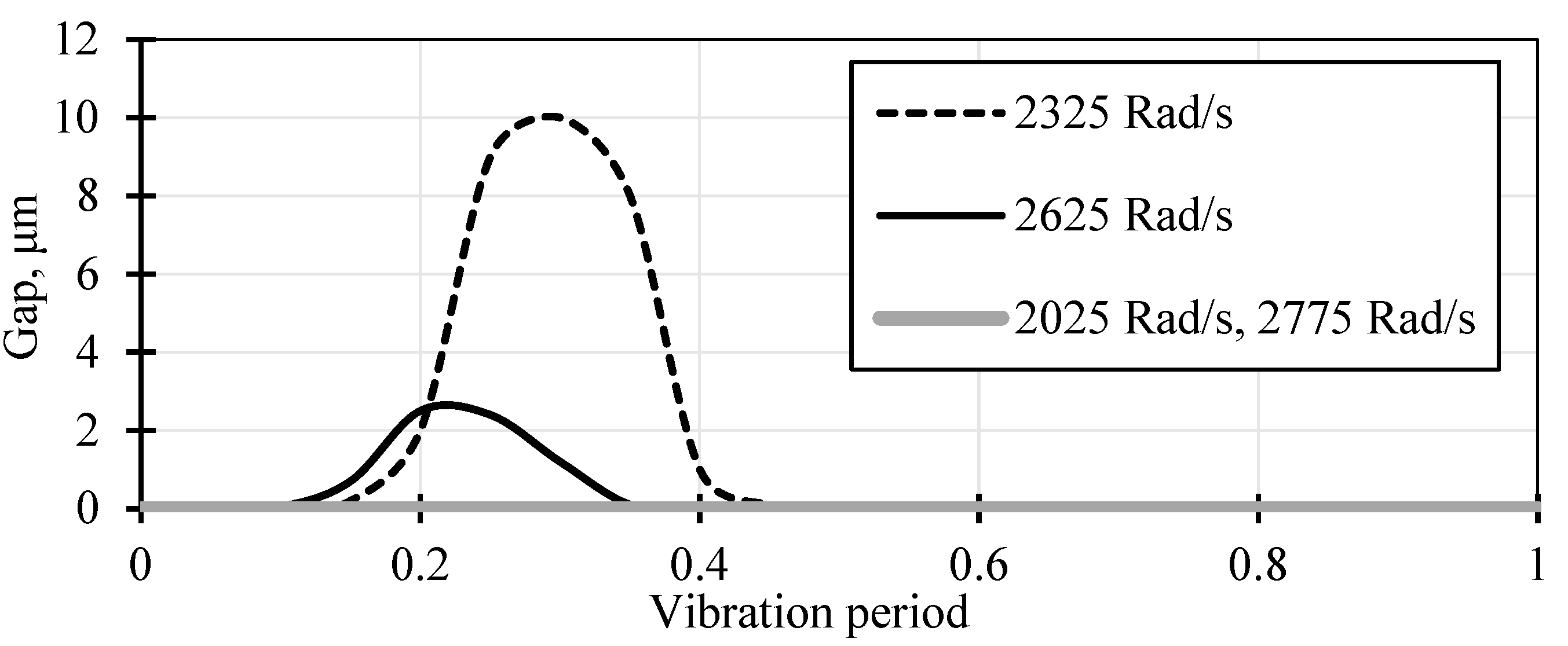
Figure 3 shows the separated gap value (h) for the different axial vibration frequencies (2025, 2325, 2625, 2775 rad/s). There is a separation of the stator seal ring from the rotor ring causing the gap value of several microns, which caused the leakage. At frequencies of 2025 rad/s and 2775 rad/s, the seal operates in contact mode.
The seal separation issue was solved by adjusting the spring and seal ring parameters. The total spring stiffness was increased to 45 kN/m while maintaining the spring force value. The mass of the sealing ring was reduced to 0.8 kg. This helps to move the separation operating range out of the excitation frequency operating range. The advantage of the developed technique is focused on predicting the separation phenomena and finding the most effective ways to eliminate such phenomena at the design stage.
3. Single-Mass Dynamic Model of Dry Gas Seal
The traditional dynamic model of a non-contact mechanical seal (or dry gas seal) is a combination of an axially movable stator seal ring, a thin fluid film between the stator seal ring and the rotor seal ring, and a spring-loaded ring with an O-ring to press the stator seal ring axially against the rotor seal ring [
2]. A thin fluid film in the case of a liquid cavity pressurisation is modelled by parallel stiffness and damping (Kelvin-Feugt model) [
11,
12]. This dynamic model is similar to the model shown in
Figure 2b, but in this case there is no force F
cls in this case (axial forces are balanced). When optimising the seal parameters, the aim is to achieve the maximum damping that will ensure the minimum change in gap value. In the case of significant seal ring vibration amplitudes (significant changes in gap value), the fluid film static stiffness dependence on the gap value have be taken into account. Experience of seal dynamic performance studies has shown that the Kelvin-Feugt model is the easiest way to take account of the non-linearity properties of the liquid film.
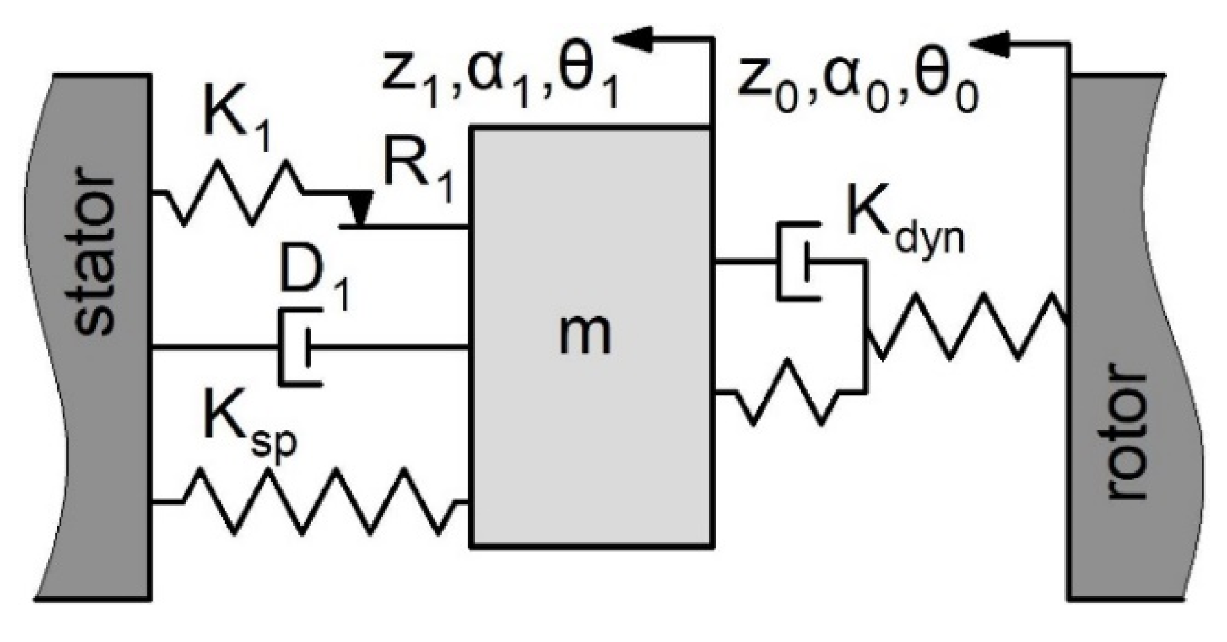
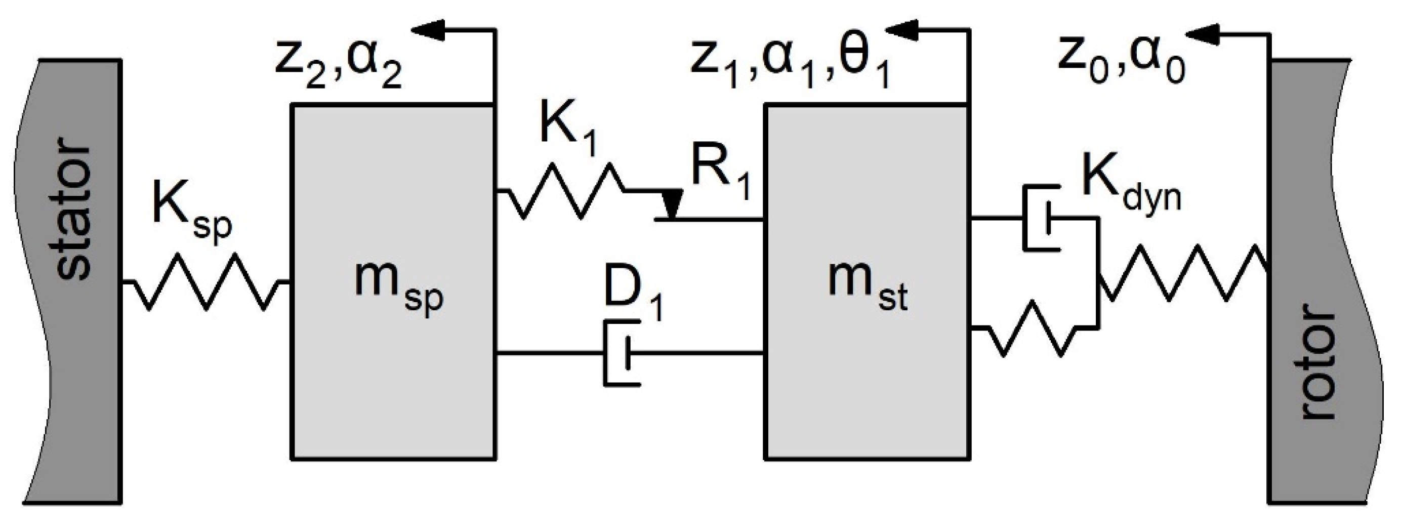
For gas, a relaxation damping model (Maxwell-Zener model) is used. This model consists of a spring element and a Kelvin-Feugt model in series. The model is characterised by the fact that the damping force does not act directly between the stator seal and rotor ring, but through an additional spring element. Singel-mass dynamic model of the dry gas seal (
Figure 4) consist of stator seal ring mass (m), an inertia-free Maxwell-Zener model (gas film, K
dyn), a spring element (spring, K
sp), damping, friction and spring element (D
1, R
1, K
1, elastomer O-ring).
There are three vibration types that can occur in a dry gas seal: axial, angular and bending. The calculation must take into account the mass and moments of inertia of the stator seal ring, the axial force and torque generated by the gas film in the gap, the properties of the spring and O-ring, and an external excitation load from the rotor ring (force and torque). The axial, angular and bending displacements of the seal ring, as well as the gap shape and its value changes, are determined during vibration. In the case of complex vibrations where the stator seal ring makes small periodic displacements (the vibration amplitude is approximately 10% of the nominal gap value) the dynamic performance (stiffness and damping coefficients) of the gas film depends linearly on the gap value changes and their rate relative to its equilibrium position.
In most practical cases it is sufficient to consider only the axial vibration. The amplitude of the rotor axial vibration or its runout is considered as the excitation load. In this case, special attention should be paid to the seal assembly process while the angular stiffness of the gas film should be high. In general, the axial, angular and bending vibrations of the stator seal ring influence each other due to cross-links. In this case, the angular displacements of the rotor ring excite the axial vibration of the stator seal ring, and so on. The vibrations of the stator seal are described by the system of equations [
1]:
where m, I, I
P – stator ring mass and moments of inertia; z
1, α
1, θ
1 , - axial, angular and bending displacement of the stator ring; F
op, M
α, M
θ - opening force and gas-dynamic moments generated by the pressurised gas film in the seal gap; F
cls, L
α, L
θ – closing force and external moments. The influence of the three types of rotor ring vibration is studied: axial, angular and bending:
where z
0amp, α
0amp, θ
0amp , - axial, angular and bending amplitude of the rotor tilt and runout.
The calculation results for a single-mass dry gas seal (classical dynamic model) are well described in the literature.
4. Two-Mass Dynamic Model of Dry Gas Seal
4.1. Model Description
If the stator seal is made entirely of graphite, the springs press the spring-loaded ring (m
sp), which in turn presses the stator seal ring through an elastomer O-ring. In this case, a two-mass dynamic model of the seal must be used (
Figure 5).
The analysis of the values of cross stiffness and damping coefficients has shown that in the studied two-mass dynamic model the following types of vibrations can occur: axial vibrations z0 → z1 → z2; angular vibrations α0 → α1 → α2; joint axial and bending vibrations z0 → z1, θ1 → z2. The bending excitation from the rotor (θ0) is very rare in practice and is therefore not considered.
In [
1,
21] it was pointed out that axial and angular vibrations can be considered separately and the ring displacements can be summed. It was also shown that axial and bending vibrations should be considered together.
The two-mass dynamic model is a general case of the three-mass dynamic model and therefore the derivation of the motion equation will be performed for a more complex model.
4.2. Calculation Results and Discussion
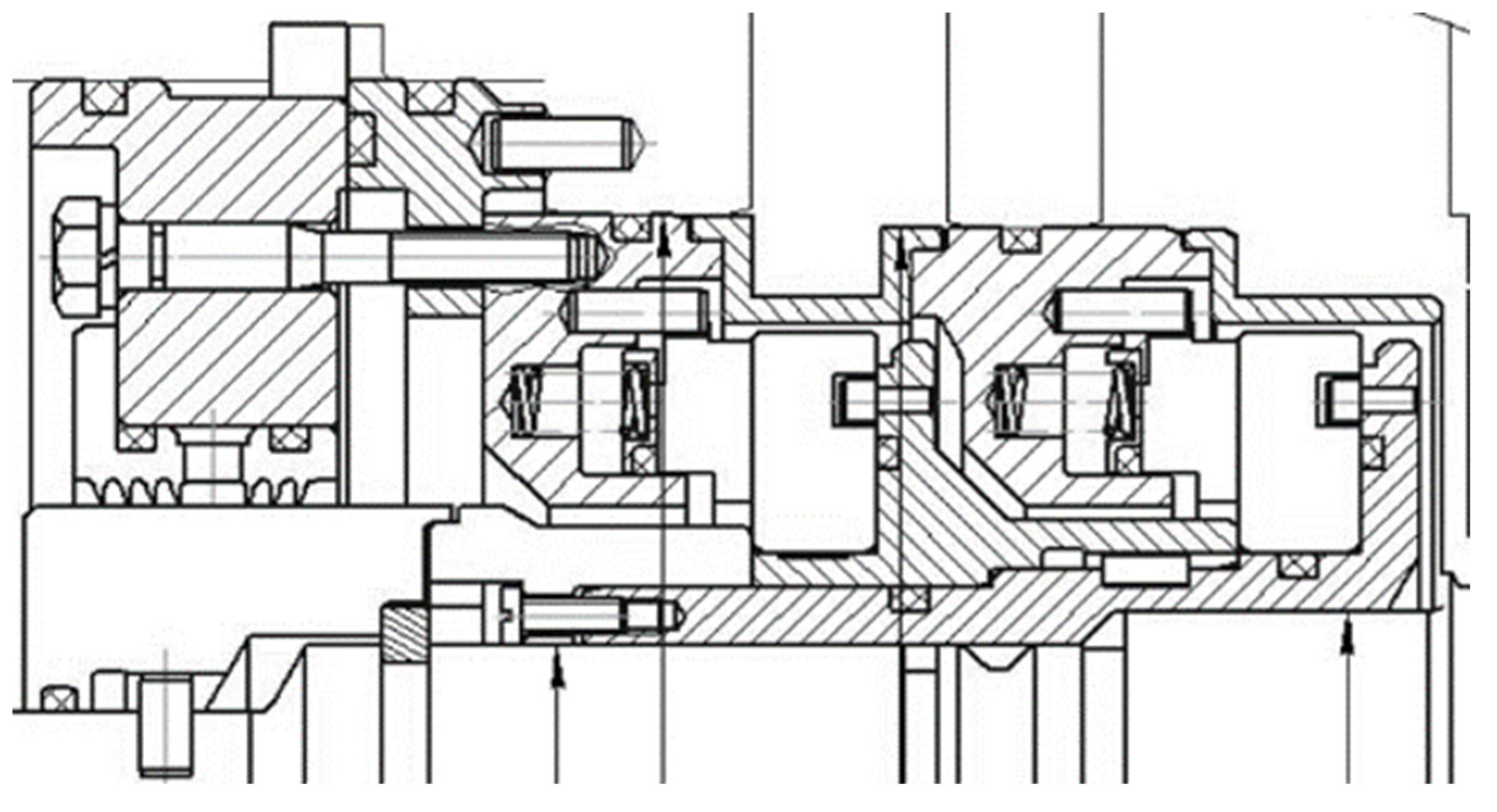
The operation of the dry gas seal for the NC-6.3 pumping unit has been studied and tested using air as a working fluid. The seal design is shown in
Figure 6.
This is a two stage dry gas seal. This is a two stage dry gas seal. The primary purpose of the first stage is to handle the pressure drop and seal the working or process gas, while the second stage acts as a barrier to ensure that no process gas enters the pressurised cavity. Two stages aslo provide redundancy. If the first stage seal fails or becomes less effective, the secondary seal can still maintain a barrier for a short period of time.
The operation parameters for the model calculation is shown in
Table 2.
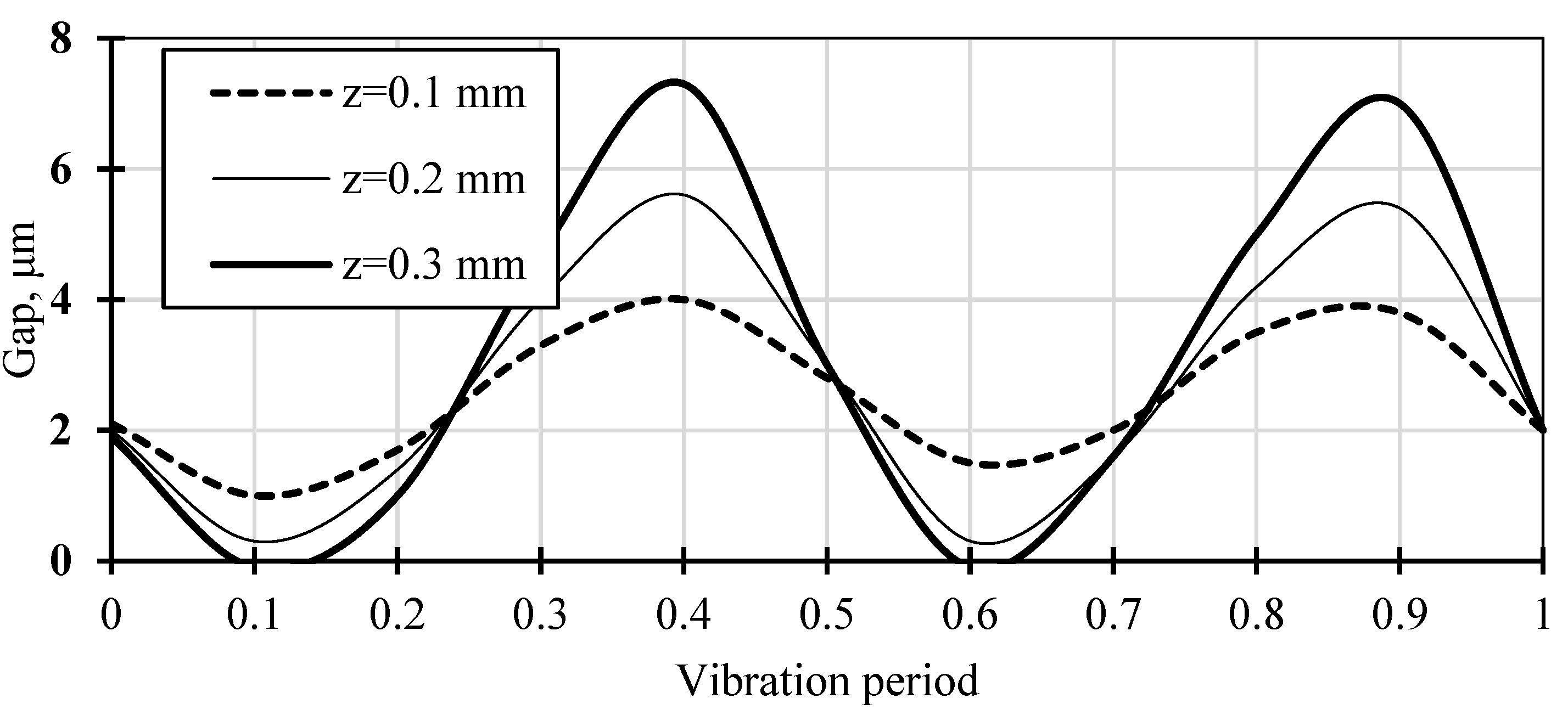
The pressure drop is 5.1 MPa. Frequency of axial rotor vibrations is 100...200 Hz. Amplitudes of axial rotor vibrations are 100...300 µm, amplitudes of angular vibrations - up to 1 mrad. The nominal value of the seal gap value is 2.5 µm.
Figure 7 shows the gap value change of a dry gas seal during the vibration period, taking into account the bending displacement of the stator seal ring.
There is impact between the seal rings in the presence of axial rotor vibrations with an amplitude of more than 200 microns, angular vibrations with an amplitude of 1 mrad and a frequency of 200 Hz. As a comparison, calculations have shown that at a vibration frequency of 100 Hz there is no impact, but the gap value decreases to 0.5...1 µm.
5. Three-Mass Dynamic Model of Dry Gas Seal
5.1. Model Description
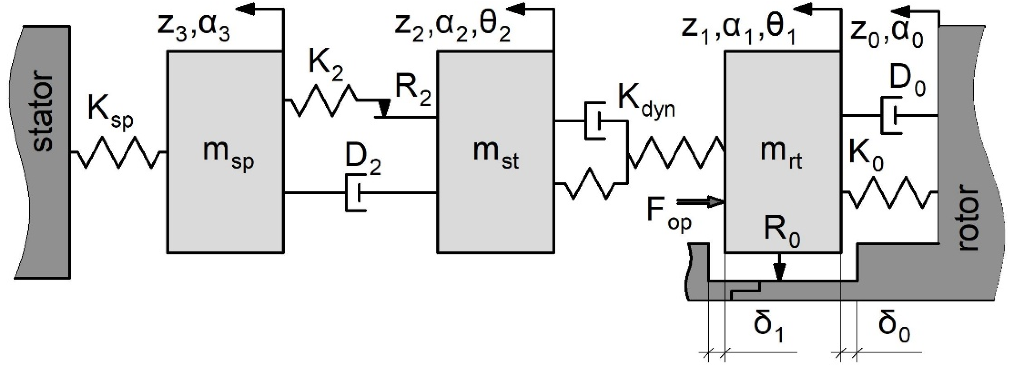
Analysis of existing and prospective designs of dry gas seals has shown that the dynamic model shown in
Figure 8 is the most appropriate when the rotor ring is flexibly mounted on the rotor [
30].
The model consists of 3 bodies (masses). The spring-loaded ring (msp) is installed in the seal housing and is pressed against the stator seal ring (mst) by a set of springs (spring stiffness Ksp). The spring masses can be taken into account for in the model by adding 1/3 of the spring mass to the spring-loaded ring mass. The O-ring seal is located between the spring-loaded ring and the stator seal ring. It is represented by stiffness element (K2), damping (D2) and friction (R2). Between the stator seal ring and the rotor seal ring (mrt) there is an inertia-free elastic-viscous model or the Maxwell-Zener model (gas film, Kdyn). Between the rotor seal ring (mrt) and the rotor face there is an additional elastomer O-ring secondary seal, which is represented by stiffness element (K0) and damping (D0). The rotor ring is pressed axially against the rotor face (δ0 = 0) by an unbalanced opening force (Fop). On the opposite side of the ring there is a gap between the rotor sleeve and the rotor seal face (δ1). The rotor seal is mounted on the shaft via either a corrugated damper or an elastomer O-ring. Mutual axial displacement of the rotor ring and the O-ring is modelled by friction (R0).
In general, case the rotor face transmits the excitation load of axial and angular vibration with amplitudes z0amp, α0amp. The rotor face may also have additional bending vibration component with amplitude θ0amp. However, the bending vibrations of the rotor face are compensated by the elastomeric O-ring deformation so that the bending excitation load is not transmitted to the rotor ring. It should be noted that the described design of the dry gas seal allows to ensure its operation in a wider range of amplitudes of axial and angular vibrations of the rotor face.
The three-mass model makes it possible to take into account the phenomenon of the seal rotor ring separation from the rotor face (δ0 > 0), and to study the effect of this phenomenon on the operation and performances of the seal.
The differential equations system of the bodies motion for the axial forces is derived:
where L – is the groove depth for the elastomeric O-ring described by the stiffness K0, while d is the cross-sectional diameter of the O-ring [
29]. The combined effect of the frictional force R2 and the damping D2 can be described by the equivalent damping
.
The system of equations is solved using the Laplace transform and reduced to an algebraic system of equations. The dynamic properties of the gas film are described as a simplified dynamic stiffness:
where
, – complex frequency domain parameter,
Harmonic axial vibration is investigated
.
is derived from the third equation of the system (7):
where
,
.
Next is derived from the third equation of the system (7) and (9):
(9). The impulse response
is the following:
where
.
Similarly, express
from the first equation of the system (7), substitute
(10) and determine the impulse response
:
where
,
,
Since the links are connected in series, the resulting the impulse response is the following:
If necessary, the amplitude-frequency and phase-frequency responses are determined:
The obtained analytical solution makes it possible to determine the position of the seal rings when the rotor ring separates from the rotor face. However, the derived dependencies are limited to the case where the stator ring successfully follows the displacements of the rotor ring. In the case where the stator ring no longer follows the axial displacements of the rotor ring, it is necessary to take into account the non-linearity of the gas film stiffness and damping properties.
In the case where the stator ring does not follow the displacements of the rotor ring, it is recommended to use a numerical solution of the three-mass model, e.g., using the classical 4th order numerical Runge-Kutta method.
5.2. Calculation Results and Discussion
The phenomenon of rotor seal ring separation was studied using the seal for the N370 natural gas pumping unit as an example, and was confirmed in practice during the operation of the gas pumping unit equipped with the John Crane seal Type 28SC (
Table 3).
The dry gas seal for the N370 pumping unit has been studied and tested using air as a working fluid. The seal design is shown in
Figure 9. Both the N370 and John Crane seal Type 28SC are the two stage dry gas seal.
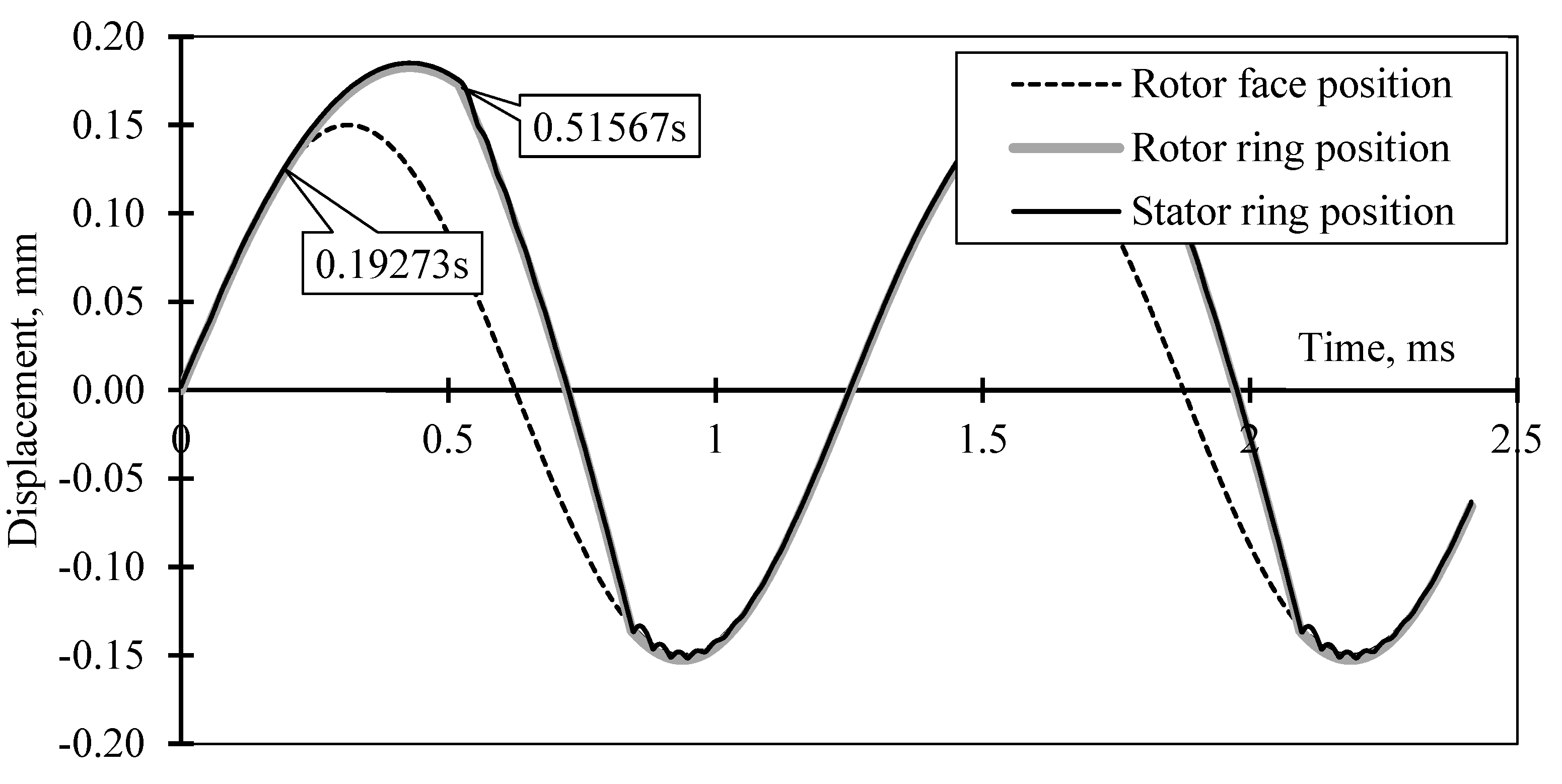
The calculation for the seal N370 was performed for an excitation load frequency of 800 Hz and an axial amplitude of 150 µm (rotor with active magnetic bearing suspension). The vibration amplitude of the rotor seal ring exceeds the rotor runout amplitude and the separation (δ
0 > 0) occurs when t = 0.19s (
Figure 10). However, due to the presence of the second stop (
Figure 8 and
Figure 9) the amplitude is limited by the gap value δ’. There are two impacts of the rotor seal ring with stops on the rotor (the second impact occurs when t = 0.51s).
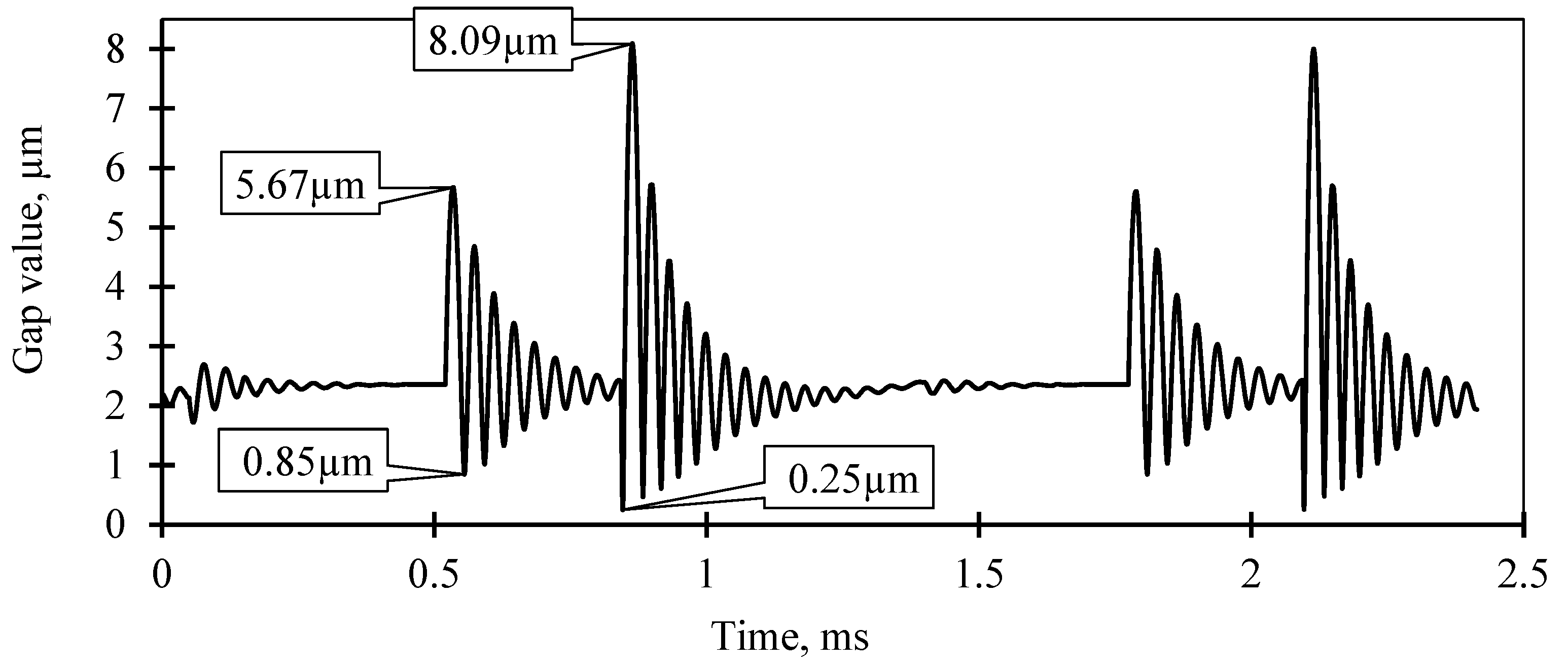
This separation phenomena has a negative effect on the seal operation and the gas film properties in the seal gap (
Figure 11). Thus, as a result of the first impact, the gap value varies in the range from 0.85 μm to 5.67 μm, and as a result of the second impact, it varies in the range from 0.25 μm to 8.09 μm.
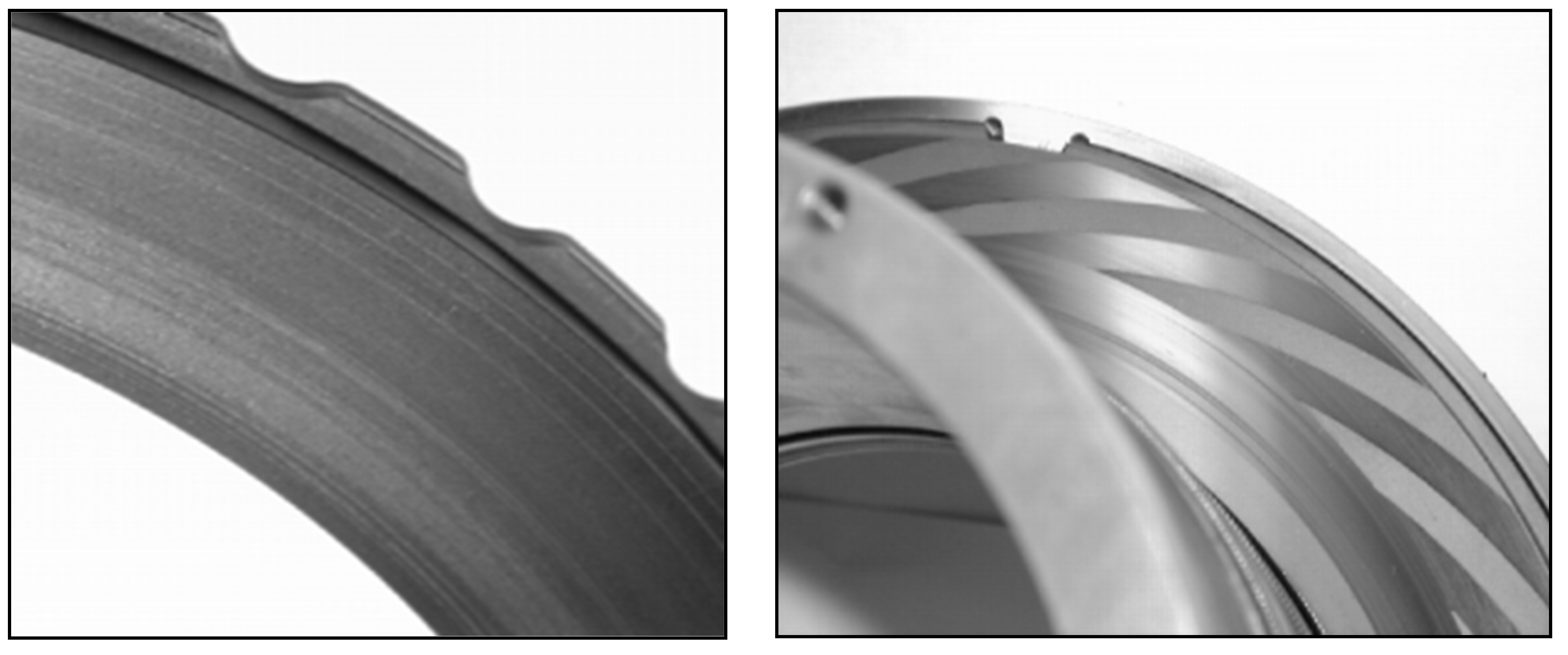
Taking into account the additional negative influence of angular and bending vibration, the dry gas seal operates with periodic impacts of the seal rings. This leads to abrasive wear of the seal rings faces and contamination of the seal gap, which in turn leads to failure of the seal unit within a short period of time (
Figure 12). It should be noted that, according to the results of the two-mass model calculation, the seal can operate normally up to a vibration frequency of 2 kHz at an axial vibration amplitude of 150 µm, which is not correct.
A similar phenomenon was observed in the second stage of the John Crane Type 28SC dry gas seal. The second stage seal operates at a low differential pressure of 17.3 kPa. The gas pumping unit was measured to be operating with an axial rotor vibration of 500 Hz and an amplitude of 55 µm. The second stage rotor seal ring due to the small value of the opening force, is pressed to the internal stop on the rotor (δ
1 = 0) by the external squeezed force of the elastomeric O-ring (the elastomeric O-ring is compressed by 0.4 mm) and the forces of the external pressure acting on the external face of the rotor ring. The three-mass model calculation results confirmed the existence of the rotor ring separation phenomenon under the measured excitation loads. The seal unit was disassembled in order to investigate the defect. (
Figure 13).
The results of the investigation confirmed the conclusions drawn from the calculations. The rotor ring of the second seal stage has wear on the sealing face on the inner diameter, whereas the rotor ring of the first seal stage does not. This is exactly the place where the rotor ring has been impacted with the rotor stop.
6. Conclusions
Rotor vibration is one of the main causes of mechanical seal failure. However, it is not always possible to explain the failure processes using traditional dynamic seal models. The described dynamic models are therefore useful for predicting the seal behavior and its performance during operation, or could be used to predict or investigate seal failure.
1) The single-mass dynamic model solves practical problems for contact mechanical seals and dry gas seals with a simple design. For the simplest mechanical contact seal, a single mass dynamic model gives the maximum rotor vibration frequency above which separation of the stator seal ring from the rotor occurs.
A single-mass dynamic model for the non-contact mechanical seal of simple design is proposed, using Kelvin-Feugt and Maxwell-Zener models to describe the dynamic response of the fluid film and the dynamic properties of the elastomer O-ring. The simplest way to describe the non-linearity behavior of a liquid film is to use the Kelvin-Feugt model. For gas, a relaxation damping model (Maxwell-Zener) is used where the damping element does not operate directly between the ring and the rotor face, but through an additional spring element. The need to include axial, angular and bending vibrations of the stator seal ring in dynamic analyses is considered. Recommendations are given for taking into account the properties of elastomer O-ring and the spring weight.
2) The two-mass dynamic model can be used to predict the performance of most dry gas seals under complex excitation loads. According to the calculation results of the two-mass dry gas seal dynamic model, the stator seal ring is able to track the rotor ring displacement in the axial direction over a wide range of rotor axial vibration frequencies and amplitudes. However, when the rotor vibration frequency increases above 100 Hz, the gap value is reduced to 0.5...1 µm, resulting in impacts between the seal faces during operation.
3) When the rotor ring is flexibly mounted on the rotor, a three-mass dynamic model of the dry ga seal is the most accurate. The developed dynamic model can be used to accurately determine the range of normal operating conditions for the advanced dry gas seal design, as well as to identify the leakage loss processes in the presence of excessive rotor vibration.
The maximum safe rotor vibration frequency determined using the two-mass dry gas seal model is more than twice that of the maximum safe frequency determined using the three-mass model. This is explained by the occurrence of the rotor ring separation from the rotor stop, resulting in impacts between the rotor ring and rotor stops. This in turn has a negative effect on the operation of the gas film in the seal gap, resulting in the gap value increasing by a factor of 4 compared to the equilibrium gap. Such operation will eventually lead to periodic impacts of the seal rings faces, which will inevitably lead to their wear, gap contamination and seal unit failure.
Author Contributions
Conceptualization, F.S. and B.R.; methodology F.S.; software, B.R.; validation F.S., B.R. B.M. and D.D.; formal analysis, B.R. and B.M.; investigation, F.S. and B.R.; resources, D.D.; data curation, B.M.,; writing—original draft preparation, B.R. and F.S.; writing—review and editing, B.R.; visualization, B.R. and B.M.; supervision, F.S.; project administration, B.R.; funding acquisition, B.R. All authors have read and agreed to the published version of the manuscript.
Funding
This work was supported by the National Key R&D Program of China (2022YFE0204100)
Data Availability Statement
The paper includes the original contributions presented in the study. Any further inquiries can be directed to the corresponding author.
Conflicts of Interest
The authors declare no conflicts of interest.
References
- Falaleev, S.V.; Vinogradov, A.S. Analysis of dynamic characteristics for face gas dynamic seal. Proc. Eng. 2015, 106, 210–217. [Google Scholar] [CrossRef]
- Ojile, J.; Teixeira, J.; Carmody, C. Mechanical seal failure analysis. J. Tribol. Trans. 2010, 53, 630–635. [Google Scholar] [CrossRef]
- Bo, R. A semi-analytical solution to the dynamic tracking of non-contacting gas face seals. ASME J. Tribol. 2002, 124, 196–202. [Google Scholar] [CrossRef]
- Varney, P.; Green, I. Impact phenomena in a non-contacting mechanical face seal. ASME J. Tribol. Trans. 2017, 139, 197–231. [Google Scholar] [CrossRef]
- Bo, R. Finite element analysis of the spiral groove gas face seal at the slow speed and the low-pressure conditions - slip flow consideration. J. Tribol. Trans. 2000, 43, 411–418. [Google Scholar] [CrossRef]
- Xu, J.; Peng, X.; Bai, S.; Meng, X. CFD simulation of microscale flow field in spiral groove dry gas seal. In Proceedings of the 8th Int. Conf. on Mechatronic and Embedded Systems and Applications, Suzhou, China, July 2012. [Google Scholar] [CrossRef]
- Wang, B.; Zhang, H.; Cao, H. Flow dynamics of a spiral-groove dry gas seal. Chin. J. Mech. Eng. (English Edition) 2013, 26, 78–84. [Google Scholar] [CrossRef]
- Wu, F.; Jiang, J.; Peng, X.; Teng, L.; Meng, X.; Li, J. Influence of Natural Gas Composition and Operating Conditions on the Steady-State Performance of Dry Gas Seals for Pipeline Compressors. Lubricants 2024, 12, 217. [Google Scholar] [CrossRef]
- Su, H.; Rahmani, R.; Rahnejat, H. Thermohydrodynamics of bidirectional groove dry gas seals with slip flow. Int. J. Thermal Sciences. 2016, 110, 270–284. [Google Scholar] [CrossRef]
- Chen, Z.; Zhao, P.; Wang, J.; Ji, H. Numerical Simulation of the Influence of the Angle of End Face Gap on the Performance of Dry Gas Seal. J. Advanced Eng. Science. 2018, 50, 203–210. [Google Scholar] [CrossRef]
- Wang, Y.; Wu, J.H.; Xu, L. Influence of power-law fluid on transient performance of liquid film seal based on the time-dependent non-Newtonian dynamic Reynolds equation. J. Tribol. Int. 2021, 159. [Google Scholar] [CrossRef]
- Xu, L.; Liu, Y.; Wu, J.H.; Yuan, X.; Hao, M.; Wang, Y.; Liu, F.; Li, Z. Transient dynamic analysis and experimental verification on lubrication regime transition during startup period of non-contacting mechanical seal in liquid oxygen turbopump. J. Tribol. Int. 2022, 176. [Google Scholar] [CrossRef]
- Falaleev, S.V.; Vinogradov, A.S. Development of a dynamic model and study of the dynamic characteristics of an end gas dynamic seal. J. Machinery Manufacture and Reliability. 2017, 46, 40–45. [Google Scholar] [CrossRef]
- Green, I.; Etsion, I. Fluid film dynamic coefficients in mechanical face seals. J. Tribol. 1983, 105, 297–302. [Google Scholar] [CrossRef]
- Miller, B.; Green, I. Numerical Formulation for the Dynamic Analysis of Spiral-Grooved Gas Face Seals. ASME J. Tribol. 1998, 120, 345–352. [Google Scholar] [CrossRef]
- Ruan, B. Numerical Modeling of Dynamic sealing behaviors of spiral groove gas face seals. J. Tribol. 2002, 124, 186–195. [Google Scholar] [CrossRef]
- Chen, Y.; Jiang, J.; Peng, X. Dynamic characteristics and transient sealing performance analysis of hyperelliptic curve groove dry gas seals. J. Tribol. Int. 2017, 116, 217–228. [Google Scholar] [CrossRef]
- Chen, Y.; Peng, X.; Jiang, J. Experimental and theoretical studies of the dynamic behavior of a spiral-groove dry gas seal at high-speeds. J. Tribol Int. 2018, 125, 17–26. [Google Scholar] [CrossRef]
- Sun, D.F.; Sun, J.J.; Ma, C.B.; Yu, Q.P. Frequency-Domain-Based Nonlinear Response Analysis of Stationary Ring Displacement of Noncontact Mechanical Seal. J. Shock and Vibration 2019, 6, 1–8. [Google Scholar] [CrossRef]
- Xu, H.; Yue, Y.; Song, P.; Mao, W.; Deng, Q.; Sun, X. Analysis on the dynamic characteristics of spiral groove dry gas seal based on the gas film adaptive adjustment model. J. Industrial Lubrication and Tribol. 2023, 75, 406–414. [Google Scholar] [CrossRef]
- Miller, B.; Green, I. Numerical Techniques for Computing Rotor dynamic Properties of Mechanical Gas Face Seals. ASME J. Tribol. 2001, 123, 395–403. [Google Scholar] [CrossRef]
- Green, I. A transient dynamic analysis of mechanical seals including asperity contact and face deformation. J. Tribol. and Lubrication Technology, 2005, 61, 52–63. [Google Scholar] [CrossRef]
- Lee, S.; Zheng, X. Analyses of both steady behavior and dynamic tracking of non-contacting spiral-grooved gas face seals. J. Computers and Fluids, 2013, 88, 326–333. [Google Scholar] [CrossRef]
- Wang, Z.; Wang, Q.; Hao, M.; Li, X.; Liu, K. The effect of thermal-elastic deformation on the sealing performance of supercritical CO2 dry gas seal, Ind. Lubr.n and Trib., 2023, 75, 950–958. [Google Scholar] [CrossRef]
- Blasiak, S.; Zahorulko, A.V. A parametric and dynamic analysis of non-contacting gas face seals with modified surfaces. J. Tribol. Int. 2016, 94, 126–137. [Google Scholar] [CrossRef]
- Teng, L.; Jiang, J.; Peng, X.; Li, J. Influence of surface grooving methods on steady and dynamic performance of spiral groove gas face seals. Alexandria Eng. J., 2023, 64, 55–80. [Google Scholar] [CrossRef]
- Chegodaev, D.E.; Falaleev, S.V. Dynamic characteristics of gas layer of face with elastic surface. Soviet J. Friction and Wear (English translation of Trenie i Iznos), 1985; 6, 136–139. [Google Scholar]
- Badykov, R.R.; Falaleev, S.V.; Wood, H.; Vinogradov, A.S. Gas film vibration inside dry gas seal gap. Proceedings of Global Fluid Power Society PhD Symposium, Samara, Russia; 2018. [Google Scholar] [CrossRef]
- Green, I.; Etsion, I. Pressure and Sgueeze Effects on the Dynamic Characteristics of Elastomer O-rings Under Small Reciprocating Motion. ASME J. Tribol. Trans, 1986, 108, 439–445. [Google Scholar] [CrossRef]
- Badykov, R.R.; Falaleev, S.V. Influence of turbomachinery vibration processes on the mechanical contact and dry gas seals. Proceedings of 2020 Int. Conf. on Dynamics and Vibroacoustics of Machines, Samara, Russia September; 2020. [Google Scholar] [CrossRef]
|
Disclaimer/Publisher’s Note: The statements, opinions and data contained in all publications are solely those of the individual author(s) and contributor(s) and not of MDPI and/or the editor(s). MDPI and/or the editor(s) disclaim responsibility for any injury to people or property resulting from any ideas, methods, instructions or products referred to in the content. |
© 2024 by the authors. Licensee MDPI, Basel, Switzerland. This article is an open access article distributed under the terms and conditions of the Creative Commons Attribution (CC BY) license (http://creativecommons.org/licenses/by/4.0/).
