1. Introduction
The measurement of the refractive index of seawater plays a pivotal role in ocean observations [
1]. Indeed, the accurate measurement of the refractive index of seawater is of great importance in research areas such as seawater flow field, ocean climate prediction and seabed resource exploration [
2,
3]. The most recent definition of the thermodynamic equations of seawater (TEOS-10) was proposed by the UNESCO/IOC SCOR/IAPSO Working Group 127 (WG127). This definition is based on a Gibbs potential function of absolute salinity, temperature and pressure and focuses on the assessment of absolute salinity [
4]. The traditional method of seawater salinity measurement is to utilise a conductivity sensor to ascertain the conductivity of seawater, after which the salinity is calculated by means of the formula [
5,
6]. Nevertheless, the silicates present in the oceans are non-ionic compounds that do not conduct electricity. Consequently, there is a bias in the measurement of seawater salinity using conductivity sensors [
7]. In such a scenario, the use of an optical method for measuring the refractive index is a beneficial approach.
Among the various optical measurement techniques for seawater refractive index, the technique based on a position-sensitive detector has become a prominent approach for high-sensitive measurements due to its advantages, including minimal influence by environmental factors and contactless measurement. In 2003, Y. Zhao et al. proposed a fibre-optic sensor for remote monitoring of salinity in water for laboratory applications. The sensor is based on the detection of beam deflection caused by changes in the refractive index of seawater, and is capable of measuring salinity using a position-sensitive detector. The salinity measurement resolution was 0.012 g kg
-1, with a system instability of 0.9 per cent [
8]. In 2009, D. Malardé et al. presented a compact optical refractive index sensor that has been applied to the in situ detection of the refractive index of seawater. The sensor is based on the principle of light refraction and employs a V-block optical structure. The device is capable of measuring the refractive index of seawater with a resolution of
[
9]. A novel optical measurement structure, based on a position-sensitive detector, has been developed with the objective of enabling higher sensitivity seawater refractive index measurements on the order of 10
-9 RIU. This allows for the development of a high-sensitivity seawater refractive index measurement system. In 2024, a method for measuring the refractive index of seawater based on a PSD was proposed. A theoretical model was developed to illustrate the relationship between laser spot displacement and refractive index change, utilising a combination of a position-sensitive detector and laser beam deflection principles. The optical measurement method was employed to establish a seawater refractive index measurement system [
10]. Nevertheless, a number of additional factors may contribute to inaccuracies in the measurement of the refractive index of seawater using a position sensitive detector. These include the configuration of the optical path within the region where the refractive index is being measured, the temperature of the system, the noise generated by the detector, and the uncertainty associated with the signal processing procedure. In the course of developing highly sensitive seawater refractive index measurement techniques, researchers have been striving to eliminate these measurement errors [
11].
The current focus of research in the field of position-sensitive detector-based measurement systems is the analysis and reduction of the influence of various factors on the measurement accuracy of the position-sensitive detector. These include the output response linearity of the position-sensitive detector [
12], the injection current [
13], the laser spot size [
14] and other factors. In the event of erroneous measurement results resulting from the presence of jitter signals, compensation systems are frequently employed in order to obtain more accurate measurement signals [
15]. Consequently, more effective solutions must be developed to achieve more accurate measurements while maintaining the optimal condition of the position-sensitive detector.
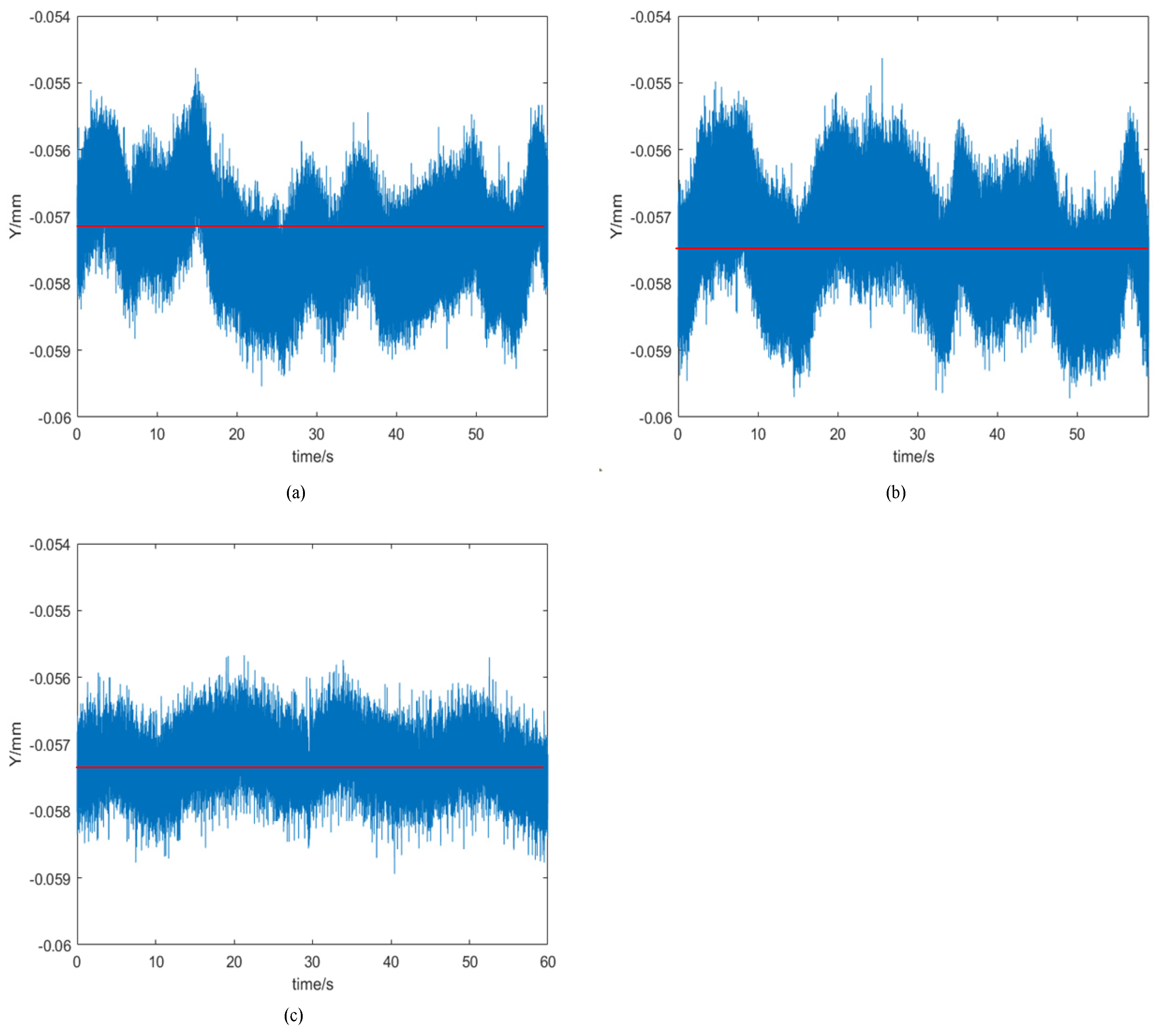
Based on these new application requirements, an analysis was conducted to identify the underlying causes of the measurement system error, specifically with regard to the existing PSD-based seawater refractive index measurement system. Firstly, a theoretical analysis was conducted to identify the error factors generated in the optical path transmission process of the seawater refractive index measurement system based on a position-sensitive detector. In order to ensure the accuracy of the seawater refractive index gradient measurement, it is essential to guarantee that the laser incident window and the laser receiving window, which collectively constitute the measurement zone, are perfectly parallel to one another. Furthermore, it is of paramount importance that the laser is incident perpendicularly upon the measurement zone. Consequently, the impact of the angle between the two windows in the measurement area and the angle of laser incidence on the sensitivity of the refractive index gradient measurement were analysed. The findings indicate that the angle between the two windows should be maintained within a narrow range of 2.06° to ensure that the sensitivity of the refractive index gradient measurement is not compromised by its angle. And the angle of laser incidence should be maintained within a narrow range of 2.06°. Then, a theoretical analysis was conducted to investigate the factors influencing the internal environment of the seawater refractive index measurement system. The analysis revealed that the interior of the measurement system was affected by temperature and atmospheric pressure. Based on the results of the analysis, an experimental study was then carried out to verify the findings. Concurrently, an analysis was conducted to identify the factors influencing the performance of the position-sensitive detector. Based on this analysis, an improvement plan was developed to address the errors caused by these influencing factors, with the objective of ensuring that the position-sensitive detector operates at its optimal level. Finally, an experimental comparison and analysis was conducted to assess the stability of the seawater refractive index measurement system before and after reducing the error factor. The experimental results demonstrate that the jitter signal of the seawater refractive index measurement system has been reduced from to , and the deviation of the refractive index has been reduced by . While the standard deviation of the seawater refractive index has been reduced from to . The experimental results show that the refractive index of seawater has been effectively reduced by adjusting the optical path and the structure of the seawater refractive index measurement system.
2. Principle of the Refractive Index Optical Measurement System
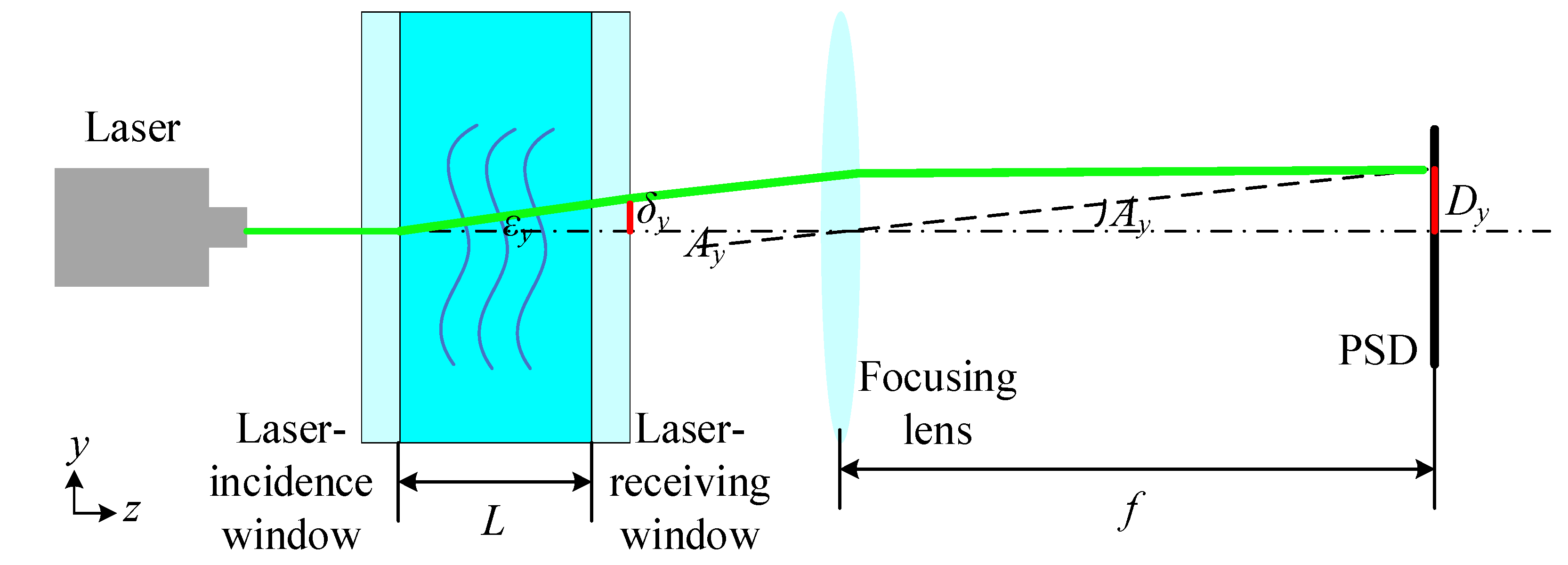
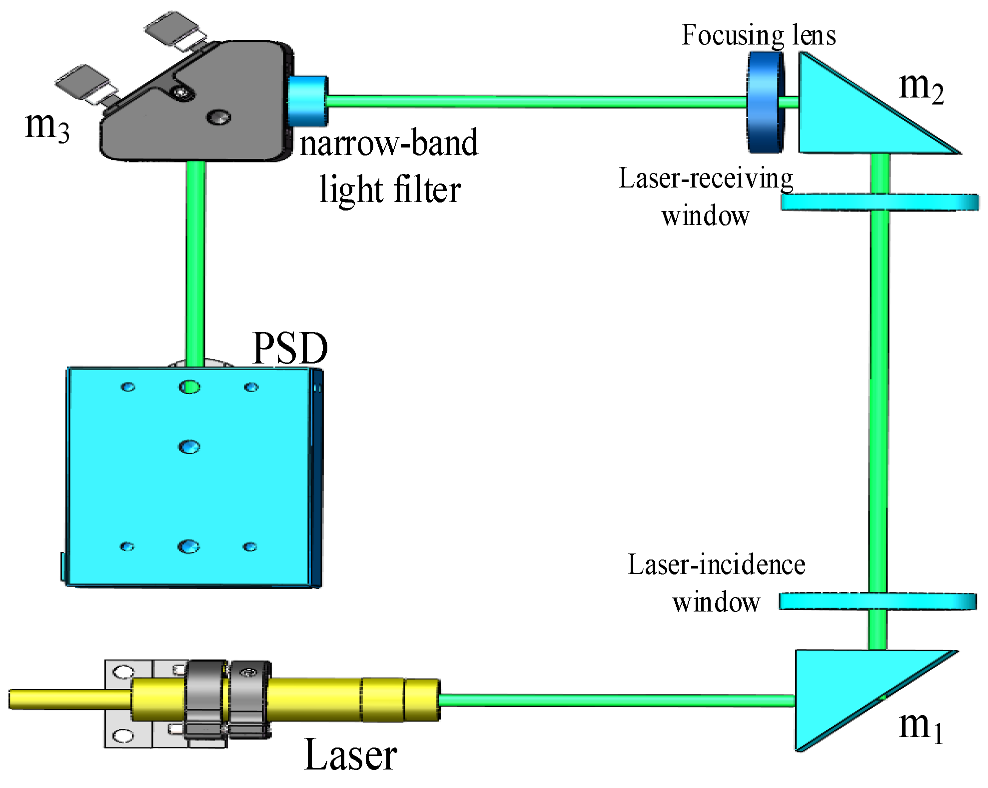
The optical seawater refractive index measurement adopts the laser beam deviation technique, and the schematic diagram of seawater refractive index measurement system based on a position-sensitive detector is shown in
Figure 1.
The light emitted by the laser passes through the laser-incidence window and reaches the area where the refractive index of seawater is measured. The refractive index gradient of seawater gives rise to a refraction phenomenon when the laser interacts with the seawater. Subsequently, the laser traverses the laser-receiving window, whereupon it is focused by the lens to a single point on the photosensitive surface of the PSD. Consequently, the coordinates of the laser spot are determined by the PSD.
The geometric theory of light refraction represents an approximation of the physical optics approach. It assumes that the measurement system optical path is a two-dimensional optical path that is isotropic in the
x and
y directions. However, since the optical path is deflected by the refractive index gradient in the
y-direction when the laser enters the measurement zone, only the refractive index gradient in the
y direction is considered. The refraction of light caused by inhomogeneity is proportional to the gradient of refractive index in each direction in the
y-planes. Consequently, the deflection rate of light rays can be expressed as in [
16], as follows:
where
n is the refractive index, z is the direction of light propagation, and the curvature of the refracted light
is represented by the gradient of the refractive index
of seawater.
The measured refractive index of the seawater can be expressed as follows [
10]:
where
n0 is the refractive index of the surrounding seawater, the
is the displacement of the light ray in the direction of
y axis, the
is the displacement on the PSD photosensitive surface, the
L is the distance between the laser-incidence window and the laser-receiving window, the
f is the focal length of the focusing lens.
As demonstrated by Equation (2), the sensitivity of a seawater refractive index measurement system based on a position-sensitive detector is contingent upon the length of the refractive index measurement zone, the focal length of the focusing lens, and the displacement on the PSD photosensitive surface. Therefore, the angle between the two windows that comprise the refractive index measurement area can result in the refraction of light during the transmission of the optical path, which in turn can lead to a deviation in the displacement on the PSD photosensitive surface. This can subsequently give rise to an error in the results of the refractive index measurement.
3. Study of the Errors Induced by the Optical Path of the Seawater Refractive Index Measurement System
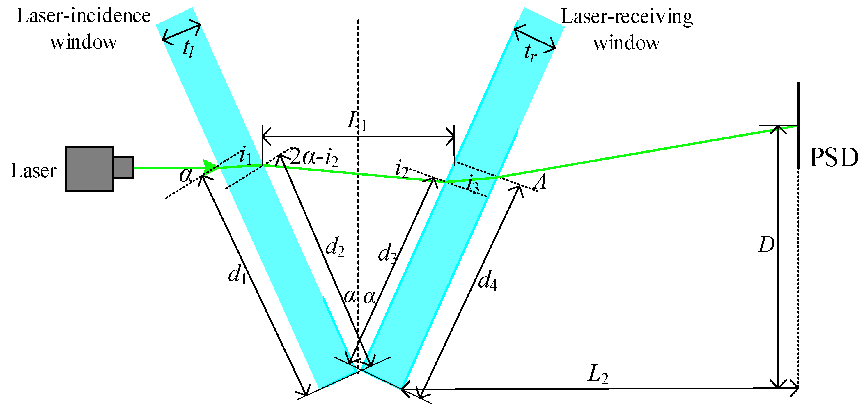
During the transmission of the optical path of the seawater refractive index measurement system, an angle between the laser-incident window and the laser-receiving window that comprise the refractive index measurement area results in the laser light refraction phenomenon, which in turn leads to an error in the seawater refractive index measurement. The optical path transmission process is depicted in
Figure 2. The laser is incident at a right angle to the main optical axis, and the first refraction occurs from the air medium through the first surface of the glass of the laser-incident window. The second refraction occurs from the glass of the laser-incident window to the refractive index measurement area of seawater. The third refraction occurs from the refractive index measurement area of seawater through the first surface of the laser-receiving window. Finally, the fourth refraction occurs from the glass of the laser-receiving window to the air medium. Following four refractions, the laser reaches the photosensitive surface of the PSD, at which point the position coordinates of the laser spot are obtained.
The law of refraction of light indicates that the angle of incidence
of the laser is refracted by the refractive index
of the air medium and the refractive index
of the window glass, resulting in the refractive angle
. This can be expressed as follows:
The laser is incident at an angle of incidence
from the window glass with a refractive index of
to the refractive index measurement area of seawater with a refractive index of
, producing an angle of refraction of
, and a refractive relation expression:
The laser is incident at an angle of incidence
from the refractive index measurement area of seawater with a refractive index of
to the window glass with a refractive index of
, which produces an angle of refraction of
. The refractive relation expression is as follows:
The laser is incident at an angle of incidence
from a window glass with a refractive index of
to an air medium with a refractive index of
, producing an angle of refraction of
. The expression for the refraction relation is:
It can be further obtained from Equations (3) and (4):
It can be further obtained from Equations (5) and (6):
The differentiation of Equations (7) and (8) can be obtained as follows:
Substitution of Equation (9) into Equation (10) and subsequent collation yields the following equation:
When the angle between the two windows is
and the length of the seawater refractive index measurement zone
, the laser is incident at the position
of the laser-incident window opening is known according to the trigonometric relationship:
The position designated
, at which the laser exits the laser-incidence window, is defined as follows:
Where is the thickness of the glass of the laser-incidence window.
The position of the laser light upon incidence upon the laser-receiving window following its passage through the refractive index measurement zone of seawater is designated as
, and it is expressed as follows:
The position designated
, at which the laser exits the laser-receiving window, is defined as follows:
Where is the thickness of the glass of the laser-receiving window.
The position
D of the received spot on the photosensitive surface can be expressed as follows:
Where represents the distance between the apex of the second surface of the laser receiving window and the PSD photosensitive surface.
The differentiation of Equation (20) yields:
Therefore,
can be expressed as follows:
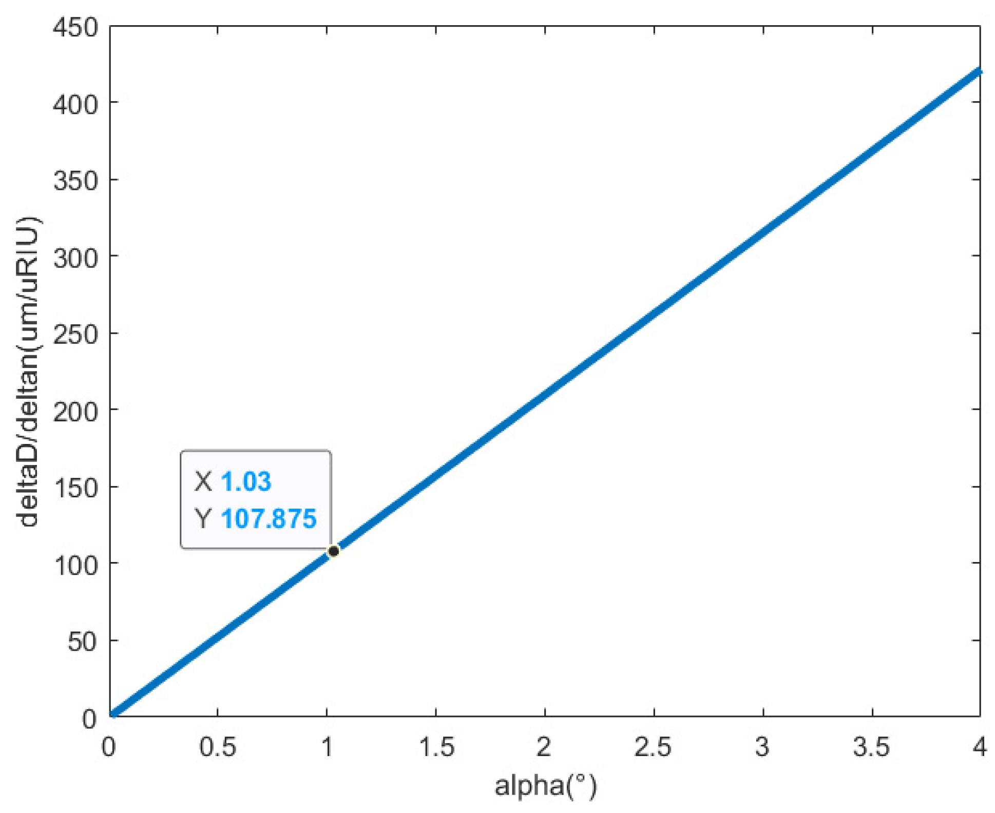
The relationship between the refractive index of the seawater and the angle between the two window glasses in the measurement area is shown in
Figure 3. According to the existing refractive index optical measurement system can be known, the selection of k9 glass as seawater refractive index measurement area of the two window glass, so the window glass refractive index
, and the window thickness
. The length of the seawater refractive index measurement area
. The distance between the apex of the second surface of the laser receiving window and the PSD photosensitive surface
. The refractive index of air under ambient conditions at standard atmospheric pressure and a temperature of 25 ℃ is
. Initial refractive index of seawater at a salinity of 35 psu
. The sensitivity of the PSD is
, and the angle between the two window glasses in the measurement area is set to be
. Given that the PSD-based optical measurement system for refractive index of seawater has a sensitivity of
, it is crucial to regulate the measurement error resulting from the angle between the two window glasses in the measurement area to be less than
, in order to ensure that this measurement error range is satisfied when the angle
. It can be demonstrated that the measurement error range is satisfied when
. The refractive index measurement sensitivity changes by
for every 0.01° change in the angle between the two window glasses in the measurement area.
4. Noise Analysis and Measurement Error Analysis of the Position-Sensitive Detector
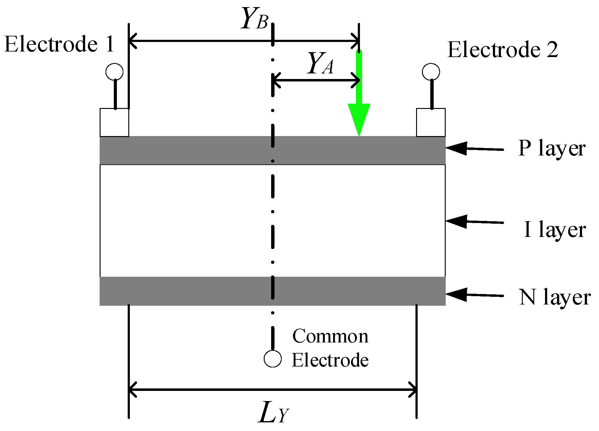
The operational principle of the PSD measurement position is shown in
Figure 4. When the laser irradiates the photosensitive surface of the PSD, electrons are excited from the valence band to the conduction band through the photovoltaic effect, thus generating a photocurrent.The PSD is a PIN structure, with the light-sensitive surface being the P layer (a uniformly distributed resistive layer), the N layer being connected to the common electrode, and the electrodes on both sides being used to extract the positional signals.
When the centre of the PSD is taken as the reference point, the laser spot irradiates the PSD photosensitive surface. This results in the generation of corresponding photocurrents by electrodes 1 and 2. The relationship between the electrode output currents and the position of the incident spot can be expressed as follows:
The output current of electrode 1 is:
The output current of electrode 2 is:
Where is the output current of electrode 1, is the output current of electrode 2, is the total output photocurrent of electrode 1 and electrode 2, is the length of the photosensitive surface, is the distance from the incident position of the laser spot to the centre of the photosensitive surface, and is the distance from the incident position of the laser spot to electrode 1.
The positional resolution of the PSD is determined by the resistor length
and the signal-to-noise ratio, and the following equation can be established according to Equation (25):
Where is the amount of output current change, is the tiny displacement.
In the case of infinitely small position displacements, the amount of noise contained in the output current signal
determines the position resolution. If the noise current of the PSD is
, the position resolution
of the PSD can be expressed as:
According to Equation (27), in order to improve the resolution of the position of the PSD, it can be done by decreasing the length of the photosensitive surface or increasing the signal photocurrent. In addition to this, PSD also has non-linear effects such as output current of electrodes at both ends and light intensity of incident spot, characteristic differences in signal amplification and processing in the subsequent processing circuit, and A/D conversion errors. Segmented optimisation BP networks and multilayer conjugate gradient optimisation algorithms are applied for nonlinear correction.
Noise exists in the PSD during operation, so the shot noise, thermal noise and operational amplifiers of the PSD are analysed according to the noise equivalent model of the PSD, and the root mean square of the total noise voltage is calculated for the case where the feedback resistor is considered.
The shot noise in PSD mainly originates from the photocurrent and dark current and can be expressed as:
Where is the electronic charge, is the dark current, is the bandwidths.
When the ratio of the interpole resistance to the feedback resistance is greater than 0.1, the feedback resistance is non-negligible, and the shot noise output voltage
is:
Where is the feedback resistance.
In PSD, the random movement of charge carriers in the resistive material due to temperature changes causes thermal noise. The thermal noise current
generated by the inter-pole resistance is:
Where is the Boltzmann constant, is the absolute temperature at which the PSD operates, and is the inter-electrode resistance.
When the ratio of the interpole resistance to the feedback resistance is greater than 0.1, the feedback resistance is non-negligible, and the thermal noise output voltage,
, generated by the resistance between the poles can be expressed as follows:
The operational amplifier equivalent noise input current
can be expressed as:
Where is the noise input voltage of the operational amplifier.
When the ratio of the interpole resistance to the feedback resistance is greater than 0.1, the feedback resistance is non-negligible, and the noise generated by the operational amplifier equivalent noise input voltage corresponds to the output voltage
denoted as:
The voltage
corresponding to the thermal noise of the feedback resistor is expressed as:
The equivalent noise voltage
of the operational amplifier is:
Where the noise current RMS value
of the PSD is expressed as:
Therefore, the RMS value of the PSD noise voltage due to the operational amplifier equivalent noise input is expressed as:
According to the PSD used in the existing seawater refractive index measurement system, it can be seen that when the bias voltage is
and the load resistance is
, the corresponding saturation photocurrent
is 10
-4 A and the bandwidth B is 10 Hz. In the operational amplifier, the feedback resistor
is
, the typical value of the inter-polar resistor
is
, and the equivalent noise input voltage
is 0.003 V. And the electron charge
is
, the Boltzmann’s constant
is
.
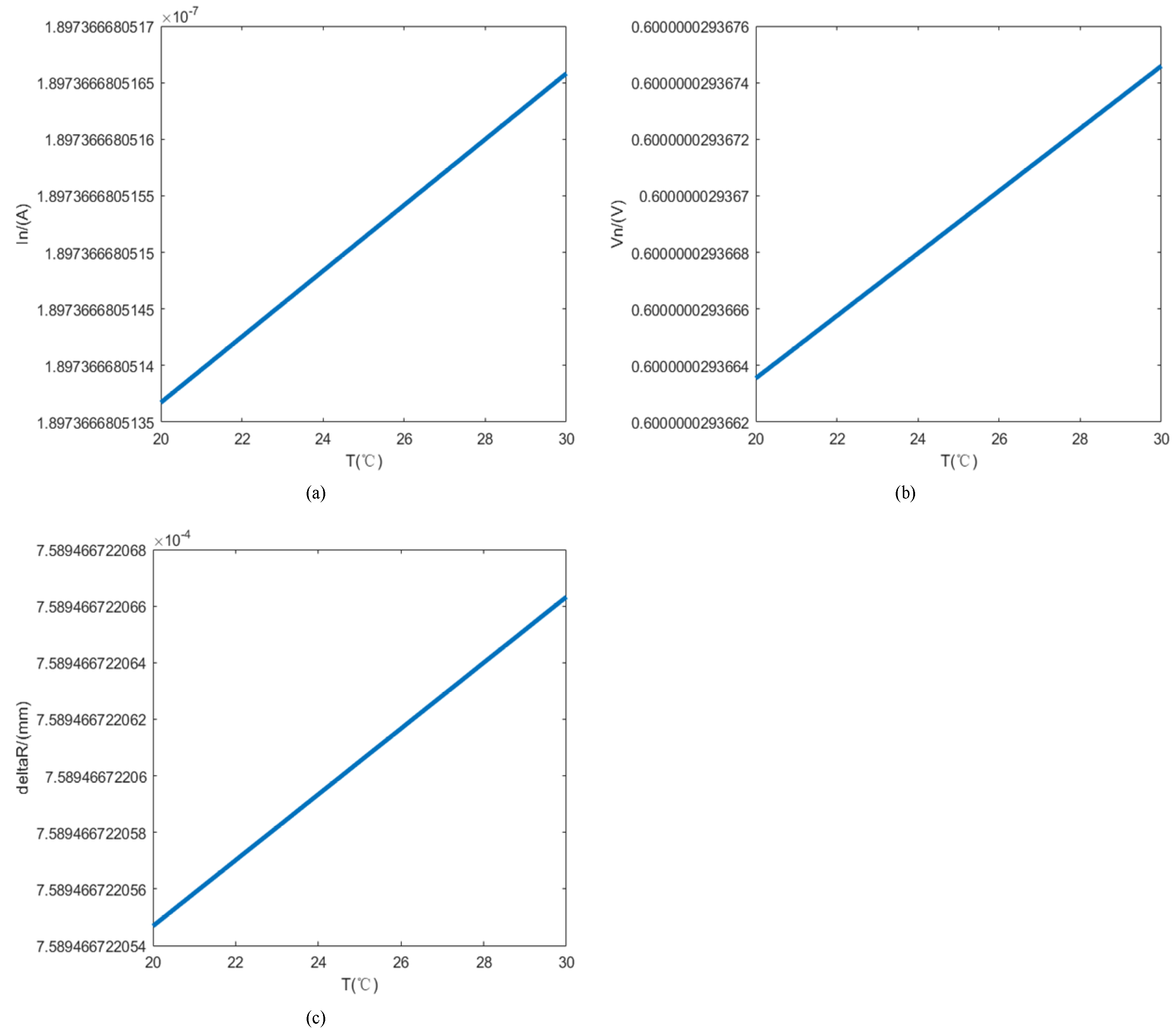
Figure 5a represents the curve of PSD noise current with temperature change from 20 to 25°C, and the noise current increases gradually with the increase of folding temperature.
Figure 5b represents the PSD noise voltage with the operating temperature from 20 to 25 °C change curve, with the increase of fold temperature noise voltage gradually increases.
Figure 5c represents the PSD position resolution with the operating temperature from 20 to 25 °C change curve, since the photosensitive side of the PSD is 4 mm long, and according to the formula (27) can be seen, with the increase of folding temperature PSD position resolution gradually increases, will lead to PSD measurement accuracy is reduced.
At the same time, there are some factors that can affect the PSD measurement accuracy during the refractive index measurement of seawater. When there is background light in the spot incident on the PSD photosensitive surface, this will result in an error in the position measurement. Therefore, a filter is added to the PSD photosensitive surface to filter out the background light other than the signal light. The spot size incident on the PSD photosensitive surface directly affects the repeatability of PSD positioning, and since the photocurrent is proportional to the irradiance on the PSD, the repeatability of PSD positioning is bound to be reduced when the spot size is large. In the seawater refractive index measurement system, a focusing lens is used to converge the light spots, thus ensuring the repeatability of PSD positioning. In the measurement system, it is difficult for the beam symmetry axis to always be parallel to the normal of the PSD photosensitive surface, so the projection of the circular spot on the PSD photosensitive surface is elliptical, which is equivalent to a large spot incidence, and the repeatability of the PSD positioning is necessarily reduced as a result.
