Submitted:
27 June 2024
Posted:
27 June 2024
You are already at the latest version
Abstract
This study aims to investigate the interfacial tension, emulsion stability, and the impact on oil displacement effectiveness of mixed systems containing nonionic surfactants and amphoteric surfactants at different ratios. To achieve this, three different emulsion stability formulations were prepared by mixing betaine and nonionic surfactants in ratios of 1:1, 3:2, and 3:1 respectively. By adjusting the proportions of betaine and nonionic surfactants, variations in interfacial tension and emulsion formation among the three mixed systems were studied to analyze the mechanism of interaction between betaine and nonionic surfactants and evaluate their effects on crude oil displacement and enhanced oil recovery in reservoirs. Subsequently, microscopic and macroscopic oil displacement experiments were conducted on the three mixed systems, along with experiments on emulsion flow resistance. The aim was to verify the oil displacement effectiveness of different mixed systems and further understand their potential applications in reservoirs. By comprehensively analyzing the experimental results, optimal ratios and conditions for the mixed systems were determined. The experimental results indicate that the emulsification system formed by mixing betaine and nonionic surfactants at a ratio of 3:1 achieves molecular synergies through electrostatic interactions and mixed adsorption with betaine, resulting in a compact arrangement of interface membranes and demonstrating a synergistic effect in reducing interfacial tension to an ultra-low value of 10 -4 mN/m. Additionally, as the proportion of betaine surfactant increases, the viscosity of the aqueous phase liquid film increases, the rate of thinning of the liquid film slows down, the rate of water release slows down, and the stability of the emulsion increases. Microscopic oil displacement experiments verified that the three mixed systems increase oil washing efficiency through low interfacial tension and emulsification stripping action, thereby increasing the oil displacement mechanism's coefficient. Emulsion flow resistance experiments demonstrated that as the proportion of betaine surfactant increases, the system exhibits better plugging ability. However, macroscopic oil displacement experiments revealed differences in compatibility between different emulsion stability solutions and rocks with different permeabilities. The mixed system of betaine and nonionic surfactants at a ratio of 3:1 exhibits the best emulsification plugging ability in rocks with a permeability of 109mD, while the 1:1 mixed system performs best in rocks with a permeability of 12mD. This holds significant theoretical and practical significance for reservoir development and enhanced production.
Keywords:
Surfactant
; Chemical enhanced oil recovery
; Stability
; Zwitterionic surfactants
; Anionic-nonionic surfactants
; amphoteric surfactants
; Betaine
1. Introduction
With the development of industry, the world's demand for energy has increased accordingly. We can either26 exploit mature oil reservoirs or discover new ones to enhance petroleum production. Typically, developing mature oil fields is economical. Currently, the majority of domestic oil fields in China have entered the middle to late development stages, reaching a high-water cut period, and suffering from severe heterogeneity, resulting in low water flooding recovery rates [1]. Consequently, enhancing the crude oil recovery of already developed oil fields has become a pressing issue in China's petroleum industry [2].
The reduction of interfacial tension (IFT) between oil and water is crucial for enhancing oil recovery [3]. By employing suitable surfactants, IFT can be effectively decreased, thereby enhancing system stability. Lowering the IFT to ultra-low values (less than 10 -2 mN/m) can significantly improve oil recovery efficiency [4]. Therefore, the quest for an efficient, cost-effective, and environmentally friendly method has become a focal point for many researchers. Traditional surfactants include anionic, cationic, nonionic, amphoteric, and zwitterionic surfactants [5]. However, for harsh reservoir conditions, the efficiency and emulsification effects of these displacing agents are often poor, making it challenging to reduce IFT to ultra-low levels [6,7,8]. Presently, commonly used zwitterionic surfactants, due to their ability to form intramolecular salts with both positive and negative charged groups, are less affected by salinity, exhibiting good interfacial activity, thermal stability, temperature resistance, and salinity tolerance [9,10,11,12]. However, betaine molecules typically possess a large hydrophilic head and a small hydrophobic tail, thus a single betaine molecule cannot form a tight adsorption film at the oil-water interface. To overcome this issue, researchers have exploited synergistic effects by enhancing the interfacial activity of the mixed system to form a dense adsorption film, thereby generating ultra-low IFT [13,14]. The electrostatic attraction between betaine and anionic surfactants leads to mixed adsorption, and electrolytes can effectively regulate the synergy between them [15]. This approach not only avoids the synthesis of complex surfactant molecular structures but also achieves ultra-low IFT within a wide concentration range [16,17]. Therefore, this method holds promising potential applications, offering an efficient, cost-effective, and environmentally friendly solution for enhancing oil recovery rates [10,18,19].
The stability of emulsions is crucial for enhancing oil recovery. Upon dissolution in a certain component, surfactants distribute themselves at the oil-water interface, reducing interfacial tension. This reduction decreases the energy required for the dispersed phase (shear phase) to form small droplets, while also lowering the surface energy necessary for droplet coalescence and merging, thereby increasing the stability of the emulsion [20]. Additionally, upon adsorption at the oil-water interface, the formed adsorption layer exhibits a gel-like elastic structure, generating a thin film around the droplets formed in the shear phase [21]. This film possesses a certain level of strength and toughness, effectively interfering with and preventing droplet coalescence, merging, and settling during collision processes, thereby further enhancing the stability of the emulsion [22]. Furthermore, the arrangement of surfactant molecules at the oil-water interface generates a certain amount of charge, resulting in a repulsive force between water droplets, further impeding their coalescence and settling and thus enhancing the stability of the emulsion [23]. Therefore, in addition to possessing ultra-low interfacial tension (IFT), surfactant solutions for complexing require a certain emulsification capability to effectively enhance oil displacement efficiency. When studying the infiltration patterns of complexing systems in homogeneous cores and their effects on enhancing oil recovery, attention is mainly focused on factors such as emulsion stability, system interfacial tension, emulsion pore-throat matching, the ease of emulsion infiltration, and surfactant adsorption on cores, and their impact on enhancing oil recovery efficiency [24]. However, there is still a lack of specific description regarding the relationship between the emulsification effect and oil displacement effect of complexing systems [25]. Emulsion infiltration patterns are complex, and describing emulsification phenomena is challenging [26,27,28,29]. Furthermore, there is currently no authoritative standard for evaluating the degree of matching between emulsion droplets and core throats [30,31]. Furthermore, emulsions belong to thermodynamically unstable systems, and during their flow in reservoir cores, they often undergo dynamic processes such as flocculation, coalescence, phase separation, and reformation. Therefore, further research and discussion are needed on whether simplified near-spherical liquid droplets can characterize the properties of emulsions and the matching relationship between emulsification intensity and reservoir characteristics. Additionally, there is a need to enhance the analysis of the efficiency of displacement fluids, including the transport capability, retention capacity, and methods to improve oil displacement efficiency of chemical flooding systems [32].
Based on the above analysis, this study selects a main agent formulation consisting of betaine and anionic nonionic surfactants to form a high-temperature, high-salinity, low-permeability in-situ emulsifying surfactant. Three different emulsion stability complexing systems are compounded to systematically investigate their performance in plugging and enhancing oil recovery.
2. Results and Discussion
2.1. Evaluation of Surfactant Ability to Reduce Interfacial Tension in Situ Emulsification Formulations
Understanding the interfacial tension (IFT) of these three surfactants is crucial. Using the spinning drop method on a TX500C interfacial tension meter, the IFT of surfactant solutions was measured. It was observed experimentally that as the concentration of surfactant solution increases, the equilibrium interfacial tension of the three surfactants significantly decreases, eventually reaching an equilibrium value (Figure 1A–D). Dynamic and equilibrium IFT values of the three surfactant solutions at different concentrations are compared in Figure 1, showing that the adsorption of surfactant molecules at the oil-water interface increases with aging time. As surfactant molecules replace interfacial solvent molecules, IFT decreases, ultimately reaching equilibrium. Dynamic IFT curves of different concentrations of branched-chain betaines and nonionic surfactants exhibit an "L" shape, while those of different concentrations of straight-chain betaines exhibit a "V" shape. This is because the hydrophilic groups of straight-chain betaine molecules contain sulfonic acid and ammonium groups, and the larger hydrophilic ion heads cannot achieve size compatibility with smaller alkyl hydrophobic chains. However, branched-chain betaine molecules have the same hydrophilic groups as straight-chain betaines, but the phenyl group of branched-chain betaines increases the size of the hydrophobic group. This makes the size of the hydrophobic group closer to that of the hydrophilic group. Nonionic surfactant molecules have two symmetrical alkyl chains, increasing the size of the hydrophobic group, allowing better size compatibility between the hydrophilic and hydrophobic groups at the interface. Therefore, the initially hydrophilic groups of straight-chain betaine molecules gradually spread at the interface, leading to an increase in IFT with aging time. In Figure 7, as the concentration of surfactant solution increases, the equilibrium IFT of these three surfactants significantly decreases. Comparatively, the equilibrium IFT of straight-chain betaine solution (2 mN/m) is higher than that of branched-chain betaine and nonionic surfactant solutions. Branched-chain betaine molecules have the same hydrophilic groups as nonionic surfactant molecules, but the phenyl group of branched-chain betaines increases the size of the hydrophobic group. Therefore, branched-chain betaines exhibit superior interfacial activity to straight-chain betaines. The equilibrium IFT of nonionic surfactant solution is higher than that of branched-chain betaine solution. Since nonionic surfactants have two symmetrical alkyl chains, the size of their hydrophobic group is significantly larger. Although the hydrophilic and hydrophobic groups at the interface have better size compatibility, they cannot form a relatively tight interface membrane. The hydrophilic and hydrophobic groups of branched-chain betaine molecules at the interface can achieve better size compatibility, and the molecules have good interfacial activity, forming a relatively tight interface membrane. However, these three surfactants alone cannot achieve ultralow IFT at the oil-water interface.
In our previous research, it has been confirmed that there is electrostatic attraction between anionic surfactants and betaine. Moreover, the synergistic effect between betaine and nonionic surfactants can effectively reduce the interfacial tension (IFT). Thus, employing a mixture of branched-chain betaine and nonionic surfactants, the equilibrium IFT values of the mixed systems are depicted in Figure 1.
Compared to the equilibrium IFT of the solution of nonionic surfactants and branched-chain betaine, the IFT values of mixed solutions with mass ratios of nonionic surfactants to branched-chain betaine at 3:2 and 3:1 is significantly decreased at various concentrations. At appropriate concentrations, the equilibrium IFT of mixed solutions of nonionic surfactants and branched-chain betaine can be reduced to 10 -4 mN/m. This phenomenon indicates a strong synergistic effect between nonionic surfactants and branched-chain betaine molecules. The primary reason is the strong electrostatic attraction between betaine and nonionic surfactant molecules. Additionally, due to the self-regulating ability of hydrophobicity, nonionic surfactant molecules can flexibly insert into the interfacial space of betaine molecules of different sizes, forming a dense adsorption film.
To summarize the above conclusions, we use Figure 3 to illustrate the synergistic effect in the mixed solution of betaine and nonionic surfactants. As shown in Figure 3a,b, nonionic surfactant molecules adhere to branched-chain betaine through electrostatic interaction, forming a tightly packed interface membrane, demonstrating the synergistic effect of reducing interfacial tension (IFT). However, as depicted in Figure 3c,d, a synergistic effect exists in the system of nonionic surfactants mixed with linear-chain betaine, but due to the mismatch in the hydrophobic part sizes ("size compatibility"), ultra-low IFT cannot be achieved.
2.2. Anionic vs. Nonionic Surfactant Effects on Emulsification of Bet
Through experiments on the stability of emulsions, the influence of non-ionic surfactants on the emulsifying effect of betaine was analyzed. The results are shown in Figure 4. In the system where branched betaine is combined with non-ionic surfactants at a ratio of 3:1, the stability is the strongest. This is because non-ionic surfactants mainly exist in the aqueous phase. When two liquid droplets approach, the stable aqueous phase film can effectively hinder the coalescence of droplets, thereby slowing down the thinning rate and water release rate of the film, thereby enhancing the stability of the emulsion.
Increasing the proportion of betaine surfactant can increase the viscosity of the aqueous phase film, thereby slowing down the thinning rate and water release rate of the film, thus enhancing the stability of the emulsion.
2.3. Control Factors of Enhanced Oil Recovery Systems
2.3.1. Microscopic Visualization of Enhanced Oil Recovery
In the model, three different strength emulsion stability systems with a volume of 0.5 pore volumes (PV) were injected separately. The oil-water flow states and residual oil distribution of different systems were measured to reveal the influence of emulsification flooding system strength parameters on the flooding effect. As indicated by the results in Figure 5 and Figure 6, the system solution initially migrated along the larger pore side in the model. During the migration process, the solution simultaneously migrated along both the larger and smaller pores. Eventually, irrespective of whether it was the larger or smaller pores, columnar residual oil was present in the model. This suggests that both the system with a 3:1 combination ratio of branched betaine and non-ionic surfactant and the system with a 3:2 combination ratio of branched betaine and non-ionic surfactant could significantly expand the impact of droplet plugging, resulting in extensive displacement of residual oil. However, the system with a 1:1 combination ratio of branched betaine and non-ionic surfactant exhibited lower emulsion stability, and its emulsification plugging ability was relatively poor, making it susceptible to the influence of channeling.
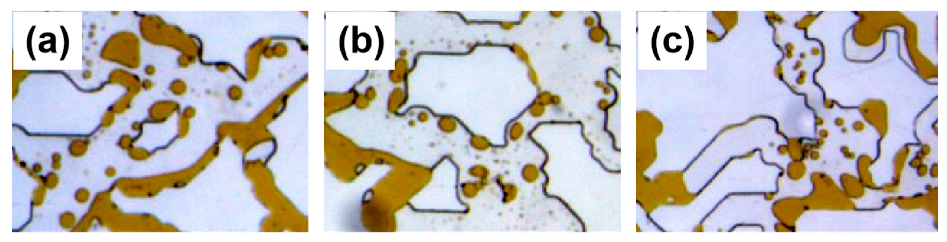
By observing the microscopic oil displacement effects of three different emulsion stability complex systems injected into the model, the oil displacement mechanism of the emulsion system is analyzed. The results, as shown in Figure 7, indicate that the crude oil detaches from the solid wall, then is stretched, deformed, and sheared into tiny oil droplets (oil-in-water emulsion droplets) with an average particle size smaller than the throat size. Such sized oil droplets are easily displaced in the porous medium, overcoming the constraints of high capillary pressure and thus improving oil displacement efficiency. Additionally, due to the small size and non-coalescence of the oil droplets, as the accumulation of droplets increases at the throat, they gradually block the passage, causing the displacing solution to spread vertically along the displacement direction, thereby increasing the spreading coefficient. Therefore, it is inferred that the microscopic oil displacement mechanism of the in-situ emulsion system enhances oil washing efficiency through low interfacial tension (IFT) and emulsification stripping effects, while the blocking effect increases the spreading coefficient.
Figure 7.
Micro-oil displacement effect of three different emulsion stability compound systems: (a) the 3:1 blended system of branched-chain betaine and nonionic surfactants; (b) the 3:2 blended system of branched-chain betaine and nonionic surfactants; (c) the 1:1 blended system of branched-chain betaine and nonionic surfactants.
2.3.2. Study on In Situ Emulsification Transport and Transport Performance
Three systems were subjected to emulsion flow resistance experiments in two permeability cores, investigating pressure variations during water flooding, chemical flooding, and subsequent water flooding stages. By comparing the magnitude of pressure changes in each stage, the systems' displacement and retention capabilities were analyzed to characterize the difficulty of passage through the pore throat and to assess the influence of reservoir permeability on emulsion flooding. The pressure variations during co-injection experiments of three different emulsion stability composite systems in cores with permeabilities of 109 × 10 -3μm -2 and 12 × 10 -3μm -2 are shown in Figure 8. According to the change curves, it can be inferred that the 3:1 composite system of branched sugar beet alkali and non-ionic surfactant exhibited a decreasing trend in pressure during the subsequent oil-water co-injection stage in the core with a permeability of 109 × 10 -3μm -2, indicating that this composite system could effectively pass through the core after in-situ emulsification, demonstrating the most suitable adaptation at this permeability. The 3:2 composite system of branched sugar beet alkali and non-ionic surfactant also showed a decreasing pressure trend at this permeability, indicating that this composite system could similarly pass through the core after in-situ emulsification, but with slightly less adaptability than the 3:1 composite system. Meanwhile, the 1:1 composite system of branched sugar beet alkali and non-ionic surfactant exhibited lower pressure during the subsequent oil-water co-injection stage in the core with a permeability of 12 × 10 -3μm -2 than the initial oil-water co-injection pressure, indicating that this composite system could also pass through the core after in-situ emulsification and exhibited the best adaptation at this permeability.
All three systems exhibited a pressure buildup phase, indicating in-situ emulsification within the core. It's noteworthy that different compound systems showed distinct pressure trends, with the 3:1 compound system exhibiting the highest pressure, followed by the 3:2 compound system, and the lowest being the 1:1 compound system. This suggests that the plugging performance of the 3:1 and 3:2 compound systems surpasses that of the 1:1 compound system. Moreover, this difference is attributed to the higher emulsion stability of the branched-chain betaine and non-ionic surfactant in the 3:1 compound system. The increase in stability typically leads to an enhancement of the Jamin effect, as a more stable emulsion can more effectively plug the pores and fractures within the reservoir, thereby reducing the flow of oil. In the core with a permeability of 109 × 10 -3μm -2, where the pore throats are larger, the 3:1 compound system can better plug the pores and displace oil, thereby increasing the recovery rate. Conversely, in the core with a permeability of 12 × 10 -3μm -2, where the pore throats are smaller, the 1:1 compound system can more smoothly pass through the pores to achieve plugging effects and subsequently enhance the recovery rate.
2.4. Optimization of In Situ Emulsification Displacement Parameters and Evaluation of Oil Recovery Effects
2.4.1. Optimization of In Situ Emulsification System Strength and Evaluation of Oil Recovery Effects
The oil displacement experiments were conducted using cores with permeabilities of 109 × 10 -3μm -2 and 12 × 10 -3μm -2, respectively. The adaptability of different surfactant systems to cores with varying permeabilities was analyzed by evaluating the magnitude of incremental oil recovery. In the core with a permeability of 109 × 10 -3μm -2, as depicted in Figure 9a, the injection of all three emulsifiers resulted in a rise in pressure during injection, indicating in-situ emulsification within the core. The extent of pressure increase reflects the emulsification plugging capability, with the 3:1 combination system of branched-chain sugar surfactant and nonionic surfactant exhibiting a higher-pressure increase, indicating a stronger emulsification plugging and spreading ability, leading to a higher incremental oil recovery.
In the core with a permeability of 12 × 10 -3μm -2, as illustrated in Figure 9b, all three emulsifiers caused pressure rise during injection, suggesting in-situ emulsification within the core. However, the subsequent water flooding pressure continued to increase with the 3:1 combination system of branched-chain sugar surfactant and nonionic surfactant, and the 3:2 combination system, indicating a mismatch between the system solution and the core. In contrast, the 1:1 combination system of branched-chain sugar surfactant and nonionic surfactant demonstrated moderate emulsification plugging capability at this permeability, leading to an improved incremental oil recovery.
The oil displacement experimental data further supported these observations. In the core with a permeability of 109 × 10 -3μm -2, the 3:1 combination system of branched-chain sugar surfactant and nonionic surfactant exhibited the best oil displacement effect, with a chemical flooding recovery rate of 17.33%, higher than the other two combination systems. Conversely, in the core with a permeability of 12 × 10 -3μm -2, the 1:1 combination system of branched-chain sugar surfactant and nonionic surfactant demonstrated the optimal performance, with a chemical flooding recovery rate of 8.87%, surpassing the other two combination systems.
Therefore, from the comprehensive analysis presented in Table 1, it can be concluded that different compound systems are required to achieve optimal oil displacement effects in cores with varying permeabilities. Specifically, the branched-chain betaine and non-ionic surfactant in a 3:1 compound system are suitable for cores with a permeability of 109 × 10 -3μm -2, whereas the 1:1 compound system is more suitable for cores with a permeability of 12 × 10 -3μm -2. This demonstrates the applicability of different compound systems to cores with different permeabilities, indicating that systems with higher emulsion stability are more suitable for cores with higher permeabilities, while those with lower emulsion stability are more suitable for cores with lower permeabilities.
2.4.2. Evaluation of Plug Combination Effects in Heterogeneous Emulsification Systems
Based on the heterogeneity of the target reservoir formation, representative sandstone core samples with permeabilities of 180 × 10 -3μm -2 and 18 × 10 -3μm -2 were selected to form a dual-tube parallel model for conducting oil displacement experiments using different single stability systems and various combination stability systems. Pressure and oil recovery were recorded, and the adequacy of different emulsification systems for plug size was determined by increasing the amplitude of oil recovery.
Oil displacement experiments were conducted using the sandstone cores with permeabilities of 180 × 10 -3μm -2 and 18 × 10 -3μm -2, as shown in Figure 10. Only 0.5PV of a 3:1 combination system of branched cyclodextrin and non-ionic surfactant was injected. During chemical flooding, the pressure continued to rise, followed by a rapid decline during subsequent water flooding. The low permeability flow rate increased continuously at the onset of chemical flooding, reaching 0.11 and then began decreasing at 1.53PV, eventually tapering to 0 by 1.71PV. This decrease was attributed to the system's solution sealing the high-permeability layer, causing severe blockage in the low-permeability layer, followed by fluid diversion towards the high-permeability layer, resulting in relatively low oil recovery from the low-permeability zone.
A 3:1 combination system of branched cyclodextrin and non-ionic surfactant was first injected at 0.17 PV, followed by a 1:1 combination system at 0.33 PV. During chemical flooding, the pressure initially increased rapidly, slowed down at 1.3 PV, and then declined during subsequent water flooding, reaching equilibrium as the PV increased. The low permeability flow rate increased to 0.08 initially during chemical flooding, began decreasing at 1.59 PV, and eventually tapered to 0 by 1.99 PV. This indicated that the initial 0.17 PV injection of the 3:1 combination system played a limited sealing role in the high-permeability zone, while the subsequent injection of the 1:1 combination system mainly entered the high-permeability zone, with inadequate coverage of the low-permeability zone.
A reverse injection sequence was employed, with a 3:1 combination system of branched cyclodextrin and non-ionic surfactant injected first at 0.33 PV, followed by a 1:1 combination system at 0.17 PV. Pressure increased rapidly at the onset of chemical flooding, decreased quickly around 1.59 PV, and then gradually declined during subsequent water flooding, stabilizing around 2.4 PV. The low permeability flow rate increased rapidly to 0.16 initially during chemical flooding, began decreasing at 1.7 PV, and tapered to 0.01 by 2.4 PV. This suggested that the initial injection of the 3:1 combination system provided some blocking effect in the high-permeability zone, while the subsequent injection of the 1:1 combination system mainly entered the low-permeability zone, resulting in effective in-situ emulsification oil displacement effects in both high and low permeability cores.
Oil displacement experiments using cores with permeabilities of 20 × 10 -3μm -2 and 2 × 10 -3μm -2 were conducted in parallel, as shown in Figure 11. Only 0.5 PV of a 1:1 combination system of branched cyclodextrin and non-ionic surfactant was injected. Pressure increased slowly at the start of chemical flooding, began to decline gradually around 1.69 PV, and continued to decrease during subsequent water flooding, stabilizing around 2.37 PV. The low permeability flow rate increased continuously at the start of chemical flooding, peaked at 0.05, then began to decline, reaching 0.01 by 2.2 PV. This indicated that the 1:1 combination system of branched cyclodextrin and non-ionic surfactant entered the high permeability core and underwent in-situ emulsification with residual oil, resulting in a continuous increase in the low permeability flow rate and expansion of the affected volume.
A 3:2 combination system of branched cyclodextrin and non-ionic surfactant was injected first at 0.17 PV, followed by a 1:1 combination system at 0.33 PV. Pressure increased rapidly at the start of chemical flooding, then decreased quickly around 1.46 PV, slowed down at 1.59 PV, and gradually declined during subsequent water flooding, stabilizing around 1.99 PV. The low permeability flow rate increased continuously at the start of chemical flooding, peaked at 0.07, then began to decline slowly, reaching 0.01 by 2.16 PV. This indicated that the initial injection of the 3:2 combination system played a blocking role in the high-permeability zone but caused damage and retention in the low-permeability core. Subsequent injection of the 1:1 combination system mainly entered the high-permeability core, with limited expansion effects.
A reverse injection sequence was employed, with a 3:2 combination system of branched cyclodextrin and non-ionic surfactant injected first at 0.33 PV, followed by a 1:1 combination system at 0.17 PV. Pressure increased rapidly at the start of chemical flooding, then decreased around 1.55 PV, and gradually declined during subsequent water flooding, stabilizing around 2.31 PV. The low permeability flow rate increased initially during chemical flooding, peaked at 0.05, then began to decline slowly, reaching 0 by 2.31 PV. This indicated that the initial injection of the 3:2 combination system effectively blocked both high and low permeability cores, making subsequent system injection difficult to move effectively into the core depths.
The oil displacement experiment data, as shown in Table 2, indicated that the best plug combination to increase oil recovery was achieved by sequentially injecting a 3:1 combination system of branched cyclodextrin and non-ionic surfactant at 0.33 PV, followed by a 1:1 combination system at 0.17 PV, into the core with a permeability of 180 × 10 -3μm -2 + 18 × 10 -3μm -2, resulting in the highest oil recovery of 82.12% in the high permeability zone and 22.73% in the low permeability zone. For the core with a permeability of 20 × 10 -3μm -2 + 2 × 10 -3μm -2, injecting only 0.5 PV of a 1:1 combination system of branched cyclodextrin and non-ionic surfactant yielded the best oil recovery results, with 58.33% in the high permeability zone and 13.71% in the low permeability zone.
3. Materials and Methods
3.1. Materials
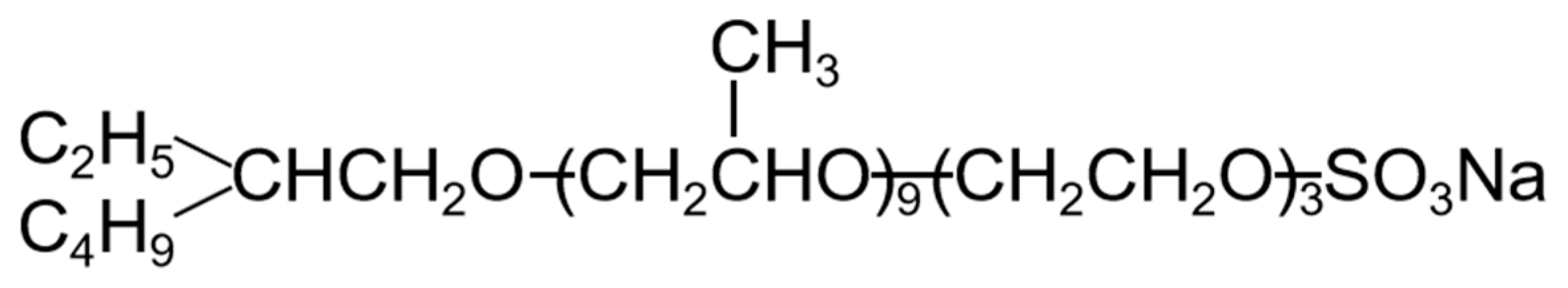
The betaine surfactants (linear and branched) and anionic-nonionic surfactant used in this paper are all from Shenzhen Infauna Biotechnology Co., Ltd., and their chemical structures are shown in Figure 12, and their purity is above 95%. The crude oil used in this paper comes from the Gas N1-N21 reservoir in Qinghai Oilfield, and its viscosity is 6.8 mPa.s at a reservoir temperature of 65°C. Secondary distilled water (resistivity > 18.2 MΩ.cm -1) was used to prepare simulated water. The composition of the formation water is shown in Table 3.
Figure 12.
Structure and abbreviation of linear-betaine (zwitterionic surfactant).
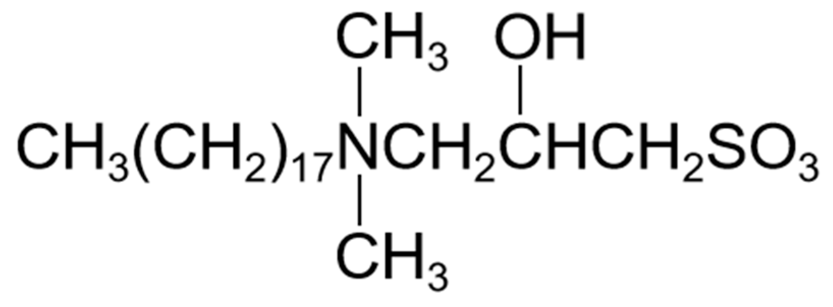
Figure 13.
Structure and abbreviation of branched-betaine (zwitterionic surfactant).
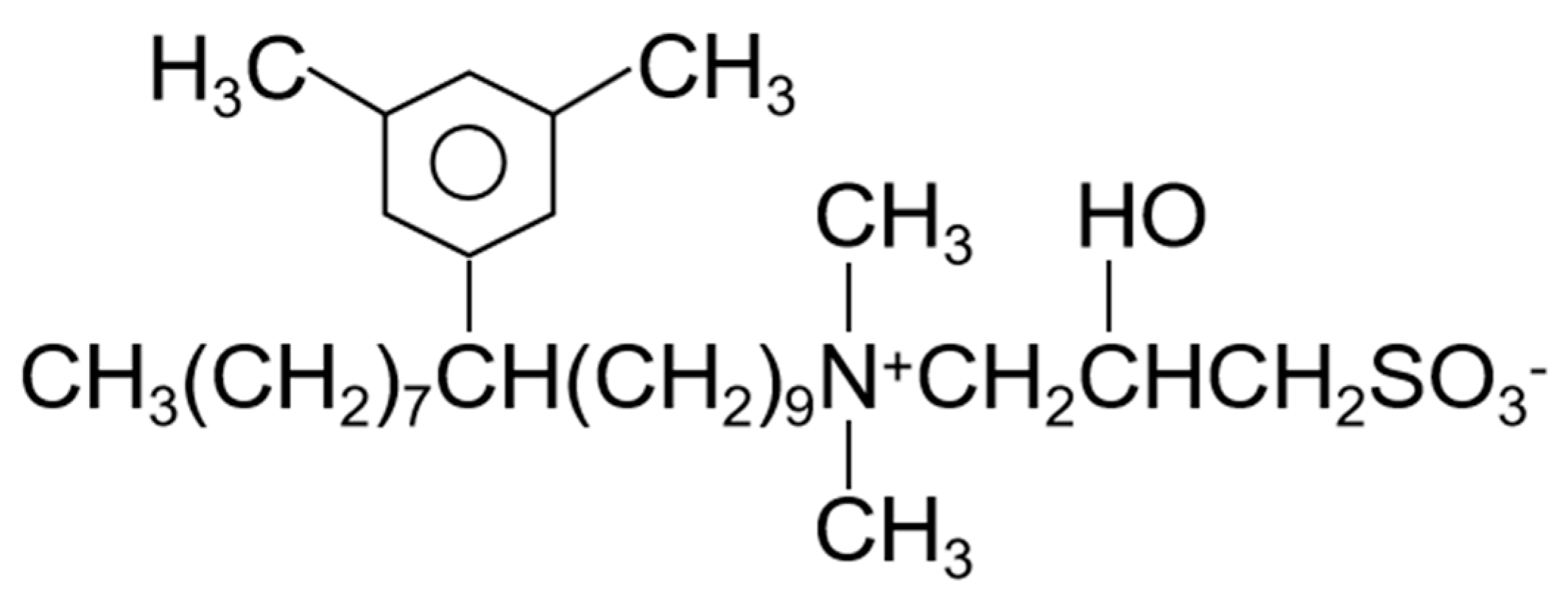
Figure 14.
Structure and abbreviation of anionic nonionic-surfactant.
3.2. Methodology
3.2.1. Preparation of Surfactant Solutions
Preparation of stock solution: Firstly, prepare a 1% surfactant solution using pre-prepared simulated water as the base liquid. This serves as the foundational liquid for the experiment.
Preparation of emulsion stability complexing systems: For the 1:1 combination system of branched betaine and anionic nonionic surfactants: According to the formulation, add the required amount of anionic nonionic surfactant stock solution to a container. Then, add the required amount of branched betaine surfactant stock solution to the same container. Finally, add the required amount of simulated water to achieve the desired total volume. Stir the solution using a magnetic stirrer to ensure thorough mixing of the two surfactants.
Preparation of 3:2 combination system of branched betaine and anionic nonionic surfactants and 3:1 combination system of branched betaine and anionic nonionic surfactants: The preparation steps for these two combination systems are the same as above, except for the varying amounts of branched betaine added during the preparation process.
3.2.2. Measurement of Surfactant Interfacial Tension
On the TX500C interface tensiometer, the interfacial tension of the surfactant solution is measured using the drop method. The preparation of the surfactant solution follows the procedure outlined in section 3.2.1. The experimental temperature is set to 65°C to mimic the temperature of oilfield reservoirs. The ratio of oil to water volume is approximately 1:200. The experimental rotational speed is set to 5000 rpm. The dynamic interfacial tension steady-state value is reached when the change in interfacial tension value within 30 minutes is less than 5wt%.
3.2.3. Emulsion Stability Determination
First, the surfactant solution and crude oil are placed in a constant temperature chamber set to the reservoir temperature for aging for 30 minutes. Then, 5g of each component is taken in a 1:1 ratio based on the oil-water ratio. They are added to a test tube in the order of water first and then oil. The mixture is stirred using a homogenizer at 10,000 rpm/min to ensure thorough emulsification, resulting in the desired emulsion. The emulsion is then kept in the constant temperature chamber for incubation, and the phase separation situation at different times is recorded.
3.2.4. Microscopic Visualization Oil Displacement Experiment
The experimental model is fabricated using glass etching. The pore structure of the model is designed based on the pore structure of low-permeability heterogeneous reservoir cores. The two-dimensional pore structure is etched onto the surface of one glass plate. The second glass plate has two holes on each side, allowing fluid to be expelled through the porous medium space.
The crude oil from the Gas-N 1-N2 1 reservoir of the Qinghai Oilfield is injected into the model at the Gas Joint Station of Gas-N 1-N2 1 reservoirs at a rate of 20 μL/min until the oil fills the entire model and there are no air bubbles in the pore throats. Subsequently, solutions of different types are injected into the model at a constant rate of 0.1 μL/min. The entire displacement process of the crude oil in the model is recorded in video mode using a microscope. In the experiment, the displacement direction of the model is from right to left.
3.2.5. Emulsion Flow Resistance Experiment
A cylindrical core with a length of 4.5 cm and a diameter of 3.8 cm was retrieved and clamped using a core holder to maintain pressure and ensure it remained either clamped or encapsulated in epoxy resin throughout subsequent testing processes. The core was subjected to vacuum treatment at room temperature and then saturated with water to ensure complete filling of the pore space. An experimental setup was assembled in a constant temperature drying oven, comprising a constant-speed pump, piston container, pressure sensor, core sample, pipelines, and valves, among other components. These components were interconnected as depicted in Figure 15 and maintained at a constant temperature of 65°C for over 3 hours to ensure thorough saturation of the core and attainment of the experimental temperature. Under original reservoir oil-water conditions, different emulsion stability formulation systems were employed for simultaneous co-injection of oil and water into short core samples at a 1:1 volume ratio, followed by co-injection of oil-composite system at a 1:1 ratio for 10 PV, and subsequently co-injection of oil-water at a 1:1 ratio for 3 PV. Pressure changes were recorded during the oil-water, oil-chemical system, and subsequent oil-water co-injection stages. Furthermore, under original reservoir oil-water conditions, different emulsion stability formulation systems were used for simultaneous co-injection of oil and water into short core samples at a 1:1 volume ratio, followed by co-injection of oil-composite system at a 1:1 ratio for 10 PV, and subsequently co-injection of oil-water at a 1:1 ratio for 3 PV. Pressure changes were monitored during the oil-water, oil-chemical system, and subsequent oil-water co-injection stages.
By comparing the pressure fluctuation magnitudes at each stage, the migration and retention of the systems were analyzed to characterize the in-situ emulsification difficulty level under fixed oil-water ratio conditions, and to investigate the plugging and adaptability of the emulsion flooding system through reservoirs with different permeabilities.
3.2.6. One-Dimensional Rock Core Chemical Flooding Experiment
A cylindrical core sample with a length of 4.5 cm and a diameter of 3.8 cm was taken and enclosed within a core holder using pressure to ensure its confinement during subsequent testing procedures. The core was either clamped within the core holder or encapsulated with epoxy resin. Subsequently, the core was vacuum-saturated with water at room temperature. It was then subjected to a constant temperature of 65°C for a minimum of 15 hours to ensure thorough wetting of the core by water and to reach the experimental temperature. Under conditions simulating those of the oil and water reservoirs in Qinghai, crude oil was injected into the core to achieve saturation. The core was placed in a constant temperature oven at 65°C and heated for 20 hours. Water flooding was then conducted at a displacement rate of 0.2 mL/min until the water cut at the outlet reached 98%, at which point the water flooding recovery factor was calculated, and the values were recorded. Subsequently, a 0.5PV (pore volume) solution of surfactant was injected, and the water flooding continued until the outlet water cut reached 98%, concluding the chemical flooding process. Pressure changes were monitored throughout the experiment.
Through one-dimensional experiments on oil displacement with different emulsion stability complex systems, pressure and recovery rate were recorded to assess the compatibility between the system and cores with varying permeability. The experimental scheme is shown in Table 4.
3.2.7. Parallel Rock Core Oil Displacement Experiment
According to the heterogeneity of the reservoir in the Gas N 1-N2 1 oilfield in Qinghai Province, a dual-tube parallel model composed of representative sandstone cores with permeability was selected for conducting oil displacement experiments under different single strength systems and different combined strength systems. Initially, the cores were placed in a clamp, followed by air injection for pressure testing. After confirming no air leakage, a vacuum was applied for 4 hours. Subsequently, formation water was injected for saturation, and the pore volume was measured and recorded. The cores were then heated for 15 hours in a constant temperature box at 65°C, followed by saturation with crude oil. After saturation, the cores were heated for an additional 20 hours at 65°C. Water flooding was conducted at a displacement rate of 0.4 mL/min until the water content at the outlet reached 98%, and the water flooding recovery rate was calculated and recorded. Next, a 0.5PV surfactant solution was injected, and water flooding continued until the outlet water content reached 98%, at which point the chemical flooding recovery rate was calculated and recorded. The appropriate plunger size for different emulsion stability composite systems was determined by calculating the increase in recovery rate. The detailed experimental procedures and processes are provided in Figure 16 and Table 5.
4. Conclusion
This study investigates the ability of mixed solutions of amphoteric and anionic nonionic surfactants to reduce interfacial tension. By comparing the adaptability of different emulsion stability composite systems formed by mixed amphoteric and anionic nonionic surfactants on cores with varying permeabilities, the study explores the application potential of emulsified enhanced oil recovery (EOR) systems in cores with different permeabilities. The main conclusions of this research can be summarized as follows:
- The mixed solution of branched-chain betaine and non-ionic surfactant can achieve an extremely low interfacial tension, as low as 10 -4 mN/m. Moreover, the stability of the branched-chain betaine and non-ionic surfactant at a ratio of 3:1 is the strongest. With an increase in the ratio of betaine to surfactant, the viscosity of the aqueous phase film also increases, thereby slowing down the thinning rate of the film and reducing water separation. Consequently, the stability of the emulsion is enhanced accordingly
- In the microscopic visualization experiments, the oil displacement mechanisms of the emulsification systems were elucidated. All three compound systems effectively expanded the influence of droplet trapping, thereby enhancing oil recovery. Among them, the branched-chain betaine and non-ionic surfactant at a ratio of 3:1 exhibited significant displacement of residual oil over a large area, with notably improved effects on both large and small pore sections.
- In the emulsion flow resistance experiments, all three compound systems, post in-situ emulsification, demonstrated the capability to pass through both 109 × 10 -3μm -2 and 12 × 10 -3μm -2 permeability cores. However, in the 109 × 10 -3μm -2 cores, characterized by larger pore throats, the 3:1 compound system displayed superior stability, effectively plugging the pores and displacing oil, thereby enhancing oil recovery. It exhibited the best compatibility. In the 12 × 10 -3μm -2 cores, with smaller pore throats, the 1:1 compound system could smoothly pass through the pores, engaging in in-situ emulsification with residual oil, thus enhancing oil recovery. It also demonstrated optimal compatibility.
- The one-dimensional core flooding experiments validated that the 3:1 compound system was best suited for the 109 × 10 -3μm -2 permeability cores, yielding a chemical flooding recovery rate of 17.33%. Similarly, the 1:1 compound system was found to be most compatible with the 12 × 10 -3μm -2 permeability cores, resulting in a chemical flooding recovery rate of 8.87%. This further confirmed the performance disparities of different compound systems under varying core permeabilities. It also affirmed that emulsions with higher stability are more suitable for cores with larger permeabilities, while those with lower stability are better suited for cores with smaller permeabilities.
- In the parallel oil displacement experiments, optimal combinations were further selected for different core permeabilities. For the core with a permeability of 180 × 10 -3μm -2 + 18 × 10 -3μm -2, the best combination was determined to be a sequential injection of 0.33PV of the 3:1 compound system (branched-chain betaine and non-ionic surfactant) followed by 0.17PV of the 1:1 compound system. Similarly, for the core with a permeability of 20 × 10 -3μm -2 + 2 × 10 -3μm -2, the best combination was found to be injecting only 0.5PV of the 1:1 compound system (branched-chain betaine and non-ionic surfactant). Further validation was conducted on the intrinsic relationship between the stability of emulsions and the permeability of rock cores. In rock cores with larger pores, emulsion systems with higher stability demonstrate superior plugging effects and possess greater spreading capabilities, thereby enhancing oil recovery rates. Conversely, in rock cores with smaller pores, emulsion systems with lower stability are more prone to penetration, leading to in-situ emulsification with residual oil. However, this process does not cause damage or retention to the rock cores or residual oil, and likewise contributes to increased oil recovery rates. Therefore, an optimal combination of emulsion stability exists for specific heterogeneous rock cores.
Author Contributions
Conceptualization, G.L.; methodology, G.L. and X.D.; writing—original draft preparation, X.D.; writing—review and editing, G.L. and X.Z.; investigation, B.H. and H.Y.; analyze and interpret data, X.W. and Y.J.; su-pervision, C.F. and K.W. All authors have read and agreed to the published version of the manuscript.
Funding
This research was supported by the National Natural Science Foundation of China (52304027). It was also supported by Chongqing Natural Science Foundation Innovation and Development Joint Fund Key Project(cstc2024ycjh-bgzxm0215).
Institutional Review Board Statement
Not applicable.
Informed Consent Statement
Not applicable.
Data Availability Statement
The original contributions presented in the study are included in the article; further inquiries can be directed to the corresponding authors.
Conflicts of Interest
The authors declare no conflicts of interest.
References
- Wilson, L.A. Physico–Chemical Environment of Petroleum Reservoirs in Relation to Oil Recovery Systems. In Improved Oil Recovery by Surfactant and Polymer Flooding; Elsevier, 1977; 1–26. [Google Scholar]
- Pal, N.; Vajpayee, M.; Mandal, A. Cationic/Nonionic Mixed Surfactants as Enhanced Oil Recovery Fluids: Influence of Mixed Micellization and Polymer Association on Interfacial, Rheological, and Rock-Wetting Characteristics. Energy Fuels 2019, 33, 6048–6059. [Google Scholar] [CrossRef]
- Mohsenatabar Firozjaii, A.; Akbari, M.; Zargar, G. Sensitivity Analysis and Optimization on Effective Parameters during Chemical Enhanced Oil Recovery (CEOR) Using Experimental Design and Numerical Simulation. Energy Sources, Part A: Recovery, Utilization, and Environmental Effects 2019, 41, 1847–1861. [Google Scholar] [CrossRef]
- Su, L.; Sun, J.; Ding, F.; Gao, X.; Zheng, L. Effect of Molecular Structure on Synergism in Mixed Zwitterionic/Anionic Surfactant System: An Experimental and Simulation Study. Journal of Molecular Liquids 2021, 322, 114933. [Google Scholar] [CrossRef]
- Zheng, J.; Luo, J.; Zhou, D.; Shen, T.; Li, H.; Liang, L.; Lu, M. Preparation and Properties of Non-Ionic Polyurethane Surfactants. Colloids and Surfaces A: Physicochemical and Engineering Aspects 2010, 363, 16–21. [Google Scholar] [CrossRef]
- Mcclements, D.J. Critical Review of Techniques and Methodologies for Characterization of Emulsion Stability. Critical Reviews in Food Science and Nutrition 2007, 47, 611–649. [Google Scholar] [CrossRef] [PubMed]
- Zhong, Q.-L.; Cao, X.-L.; Zhu, Y.-W.; Ma, B.-D.; Xu, Z.-C.; Zhang, L.; Ma, G.-Y.; Zhang, L. Studies on Interfacial Tensions of Betaine and Anionic-Nonionic Surfactant Mixed Solutions. Journal of Molecular Liquids 2020, 311, 113262. [Google Scholar] [CrossRef]
- Mohamad-Aziz, S.N.; Mishra, P.; Zularisam, A.W.; Sakinah, A.M.M. Isooctane-Based Anionic and Zwitterionic Surfactant: Synergistic Interaction of Mixed Reverse Micelle and Solubilisation of Erythromycin. Journal of Molecular Liquids 2019, 286, 110882. [Google Scholar] [CrossRef]
- Zhang, X.; Guo, Y.; Liu, J.; Zhu, Y.; Hu, J.; Feng, R.; Fu, C. Adaptability of a Hydrophobically Associating Polyacrylamide/Mixed-surfactant Combination Flooding System to the Shengli Chengdao Oilfield. J of Applied Polymer Sci 2014, 131. [Google Scholar] [CrossRef]
- Xiao, Z.; Dexin, L.; Yue, L.; Lulu, L.; Jie, Y. Synergistic Effects between Anionic and Amphoteric Surfactants on Promoting Spontaneous Imbibition in Ultra-Low Permeability Reservoirs: Study of Mechanism and Formula Construction. Colloids and Surfaces A: Physicochemical and Engineering Aspects 2021, 625, 126930. [Google Scholar] [CrossRef]
- Li, Z.; Wu, H.; Hu, Y.; Chen, X.; Yuan, Y.; Luo, Y.; Hou, J.; Bai, B.; Kang, W. Ultra-Low Interfacial Tension Biobased and Catanionic Surfactants for Low Permeability Reservoirs. Journal of Molecular Liquids 2020, 309, 113099. [Google Scholar] [CrossRef]
- Ludwig, M.; Geisler, R.; Prévost, S.; Von Klitzing, R. Shape and Structure Formation of Mixed Nonionic–Anionic Surfactant Micelles. Molecules 2021, 26, 4136. [Google Scholar] [CrossRef] [PubMed]
- Howe, A.M.; Pitt, A.R. Rheology and Stability of Oil-in-Water Nanoemulsions Stabilised by Anionic Surfactant and Gelatin 1) Addition of Nonionic, Cationic and Ethoxylated-Cationic Co-Surfactants. Advances in Colloid and Interface Science 2008, 144, 24–29. [Google Scholar] [CrossRef] [PubMed]
- Akanno, A.; Guzmán, E.; Fernández-Peña, L.; Ortega, F.; G. Rubio, R. Surfactant-Like Behavior for the Adsorption of Mixtures of a Polycation and Two Different Zwitterionic Surfactants at the Water/Vapor Interface. Molecules 2019, 24, 3442. [Google Scholar] [CrossRef] [PubMed]
- Gerola, A.P.; Costa, P.F.A.; Nome, F.; Quina, F. Micellization and Adsorption of Zwitterionic Surfactants at the Air/Water Interface. Current Opinion in Colloid & Interface Science 2017, 32, 48–5. [Google Scholar]
- Zhang, R.; Somasundaran, P. Advances in Adsorption of Surfactants and Their Mixtures at Solid/Solution Interfaces. Advances in Colloid and Interface Science 2006, 123–126, 213–229. [Google Scholar] [CrossRef] [PubMed]
- Gerola, A.P.; Costa, P.F.A.; Quina, F.H.; Fiedler, H.D.; Nome, F. Zwitterionic Surfactants in Ion Binding and Catalysis. Current Opinion in Colloid & Interface Science 2017, 32, 39–47. [Google Scholar]
- Jurjevec, S.; Žagar, E.; Kovačič, S. Functional Macroporous Amphoteric Polyelectrolyte Monoliths with Tunable Structures and Properties through Emulsion-Templated Synthesis. Journal of Colloid and Interface Science 2020, 575, 480–488. [Google Scholar] [CrossRef] [PubMed]
- Silva, G.T.M.; Quina, F.H. Ion–Micelle Interactions and the Modeling of Reactivity in Micellar Solutions of Simple Zwitterionic Sulfobetaine Surfactants. Current Opinion in Colloid & Interface Science 2019, 44, 168–176. [Google Scholar]
- Nome, F.; Romsted, L. Reactivity in Colloidal Systems and at Interfaces. Current Opinion in Colloid & Interface Science 2013, 18, 1–2. [Google Scholar]
- Kamal, M.S.; Sultan, A.S.; Hussein, I.A. Screening of Amphoteric and Anionic Surfactants for cEOR Applications Using a Novel Approach. Colloids and Surfaces A: Physicochemical and Engineering Aspects 2015, 476, 17–23. [Google Scholar] [CrossRef]
- Liu, Z.; Zhao, G.; Brewer, M.; Lv, Q.; Sudhölter, E.J.R. Comprehensive Review on Surfactant Adsorption on Mineral Surfaces in Chemical Enhanced Oil Recovery. Advances in Colloid and Interface Science 2021, 294, 102467. [Google Scholar] [CrossRef] [PubMed]
- Chaturvedi, K.R.; Sharma, T. Rheological Analysis and EOR Potential of Surfactant Treated Single-Step Silica Nanofluid at High Temperature and Salinity. Journal of Petroleum Science and Engineering 2021, 196, 107704. [Google Scholar] [CrossRef]
- Lv, W.; Bazin, B.; Ma, D.; Liu, Q.; Han, D.; Wu, K. Static and Dynamic Adsorption of Anionic and Amphoteric Surfactants with and without the Presence of Alkali. Journal of Petroleum Science and Engineering 2011, 77, 209–218. [Google Scholar] [CrossRef]
- Llinares, R.; Ramírez, P.; Carmona, J.; Carrillo, F.; Munñoz, J. Formulation and Optimization of Emulsions Based on Bitter Fennel Essential Oil and EO/BO Block Copolymer Surfactant. Colloids & Surfaces A Physicochemical & Engineering Aspects 2017, 536, 142–147. [Google Scholar]
- Santos, J.; Trujillo-Cayado, L.A.; Calero, N.; Alfaro, M.C.; Muñoz, J. Development of Eco-Friendly Emulsions Produced by Microfluidization Technique. Journal of Industrial & Engineering Chemistry 2016, 36, 90–95. [Google Scholar]
- Suleimanov, B.A.; Ismailov, F.S.; Veliyev, E.F. Nanofluid for Enhanced Oil Recovery. Journal of Petroleum Science & Engineering 2011, 78, 431–437. [Google Scholar]
- Adibhatla, B.; Mohanty, K. Oil Recovery From Fractured Carbonates by Surfactant-Aided Gravity Drainage: Laboratory Experiments and Mechanistic Simulations. Spe Reservoir Evaluation & Engineering 2006, 11, 119–130. [Google Scholar]
- Raikos, V. Encapsulation of Vitamin E in Edible Orange Oil-in-Water Emulsion Beverages: Influence of Heating Temperature on Physicochemical Stability during Chilled Storage. Food Hydrocolloids 2017, 72, 155–162. [Google Scholar] [CrossRef]
- Domian, E.; Brynda-Kopytowska, A.; Oleksza, K. Rheological Properties and Physical Stability of o/w Emulsions Stabilized by OSA Starch with Trehalose. Food Hydrocolloids 2015, 44, 49–58. [Google Scholar] [CrossRef]
- Mengual, O.; Meunier, G.; Cayré, I.; Puech, K.; Snabre, P. TURBISCAN MA 2000: Multiple Light Scattering Measurement for Concentrated Emulsion and Suspension Instability Analysis. Talanta 1999, 50, 445–456. [Google Scholar] [CrossRef]
- Esfandyari, H.; Moghani Rahimi, A.; Esmaeilzadeh, F.; Davarpanah, A.; Mohammadi, A.H. Amphoteric and Cationic Surfactants for Enhancing Oil Recovery from Carbonate Oil Reservoirs. Journal of Molecular Liquids 2021, 322, 114518. [Google Scholar] [CrossRef]
Figure 1.
Dynamic IFT of oil-water Conditions of Three Surfactants with Different Concentrations in Gas United Station: (a) Linear-betaine; (b) Branched-betaine; (c) Anionic-nonionic surfactant; (d) Comparison chart of dynamic IFT of three surfactants.
Figure 1.
Dynamic IFT of oil-water Conditions of Three Surfactants with Different Concentrations in Gas United Station: (a) Linear-betaine; (b) Branched-betaine; (c) Anionic-nonionic surfactant; (d) Comparison chart of dynamic IFT of three surfactants.
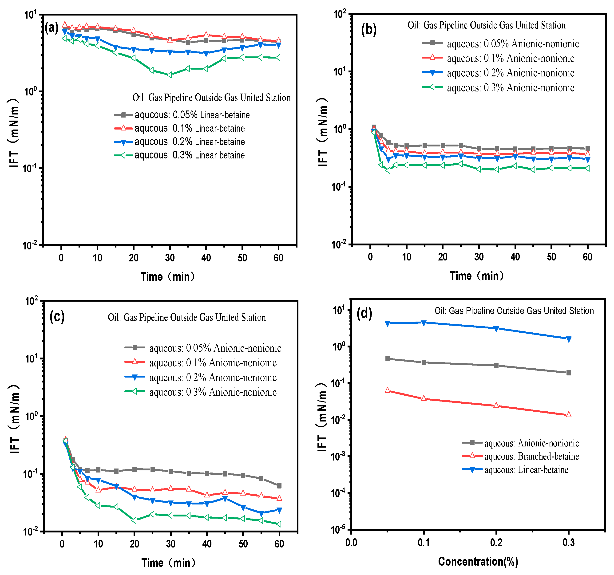
Figure 2.
Comparison chart of dynamic IFT of oil-water conditions of four surfactants in Gas United Station.
Figure 2.
Comparison chart of dynamic IFT of oil-water conditions of four surfactants in Gas United Station.
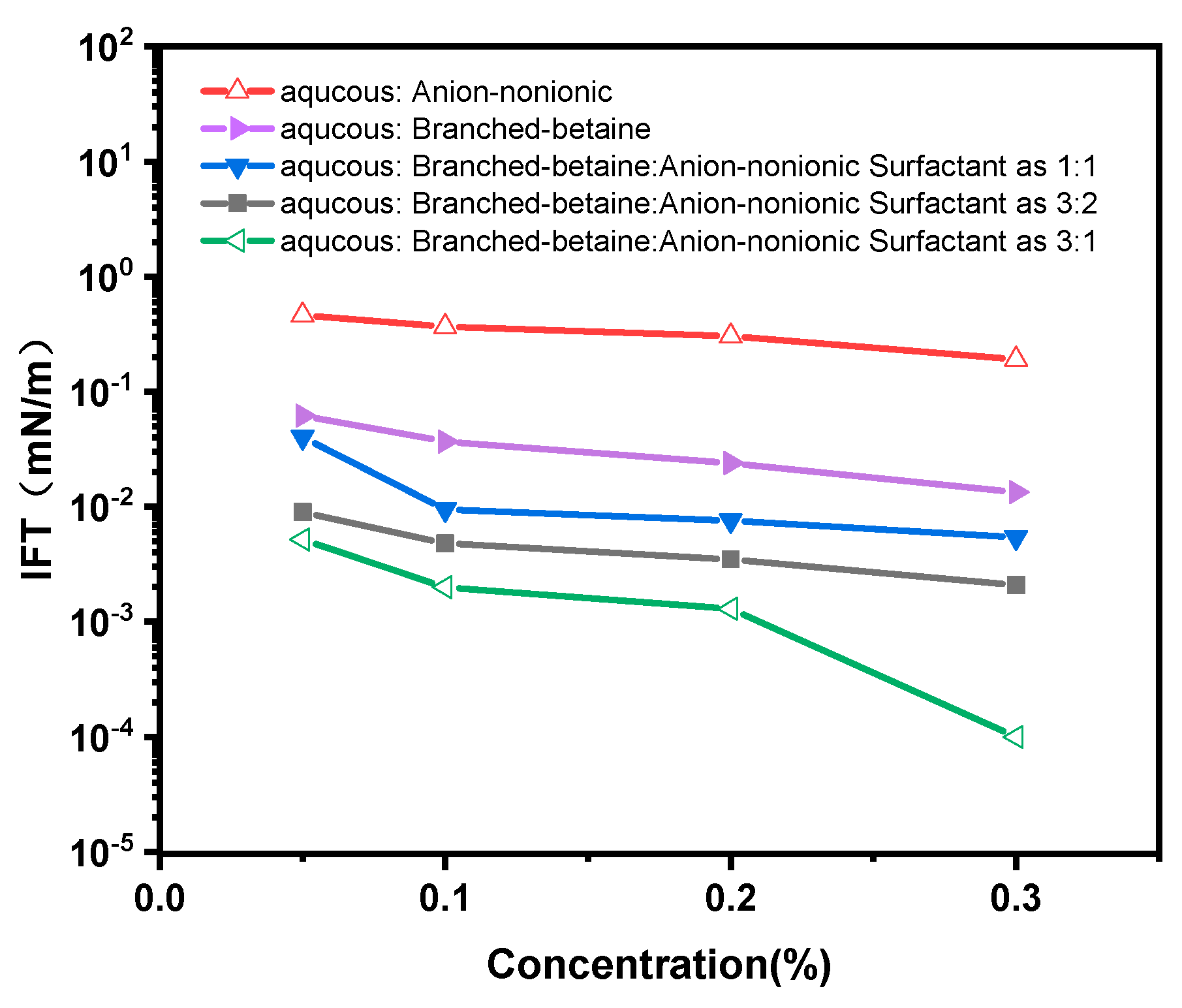
Figure 3.
Molecular structure: (a) Linear-betaine; (b) Anionic-nonionic surfactant + linear-betaine; (c) Branched-betaine; (d) Anionic-nonionic surfactant + branched-betaine.
Figure 3.
Molecular structure: (a) Linear-betaine; (b) Anionic-nonionic surfactant + linear-betaine; (c) Branched-betaine; (d) Anionic-nonionic surfactant + branched-betaine.
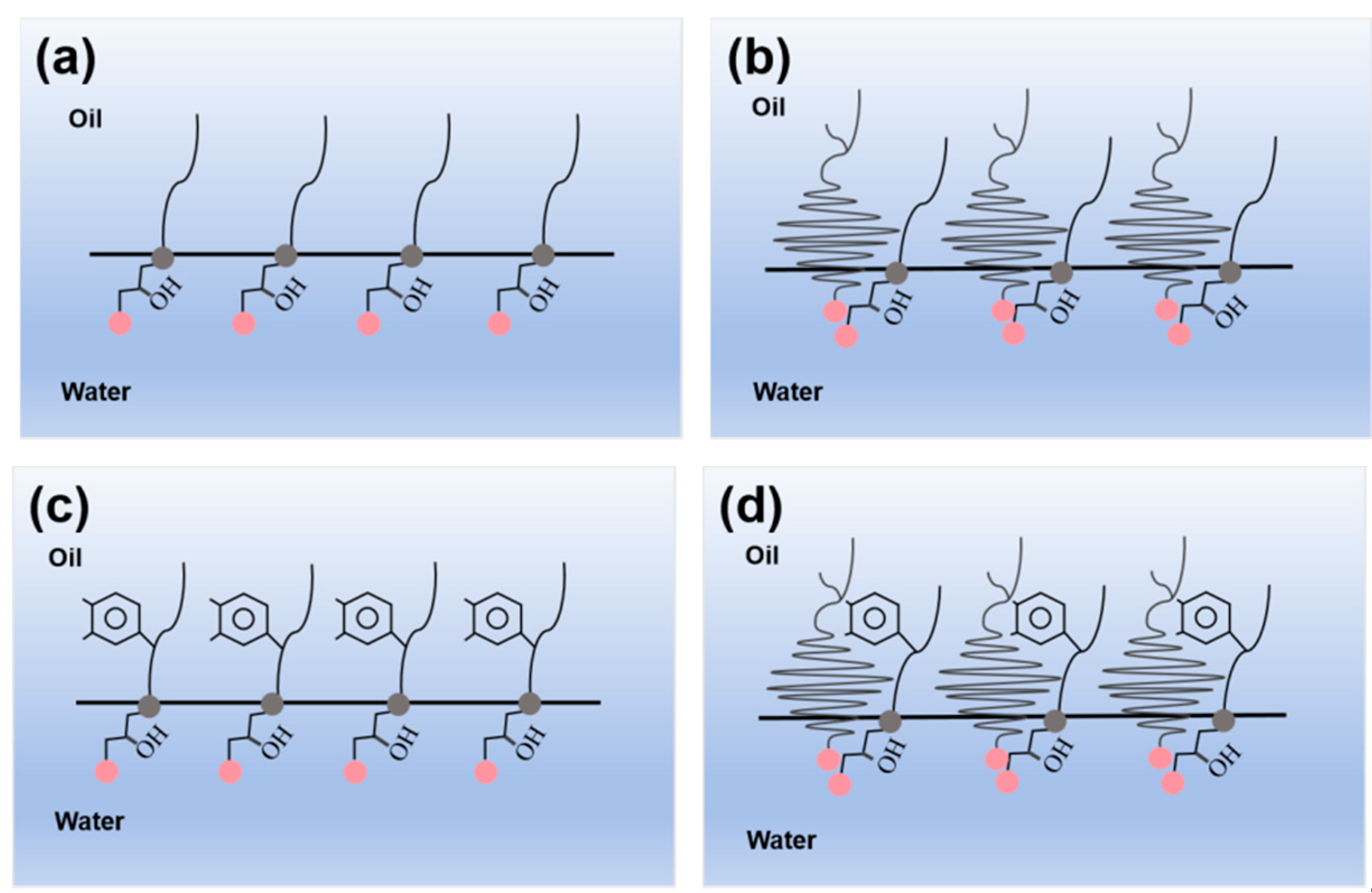
Figure 4.
Stability of three different emulsion stability compound systems: (a)the 1:1 blended system of branched-chain betaine and nonionic surfactants; (b)the 3:2 blended system of branched-chain betaine and nonionic surfactants; (c)the 3:1 blended system of branched-chain betaine and nonionic surfactants.
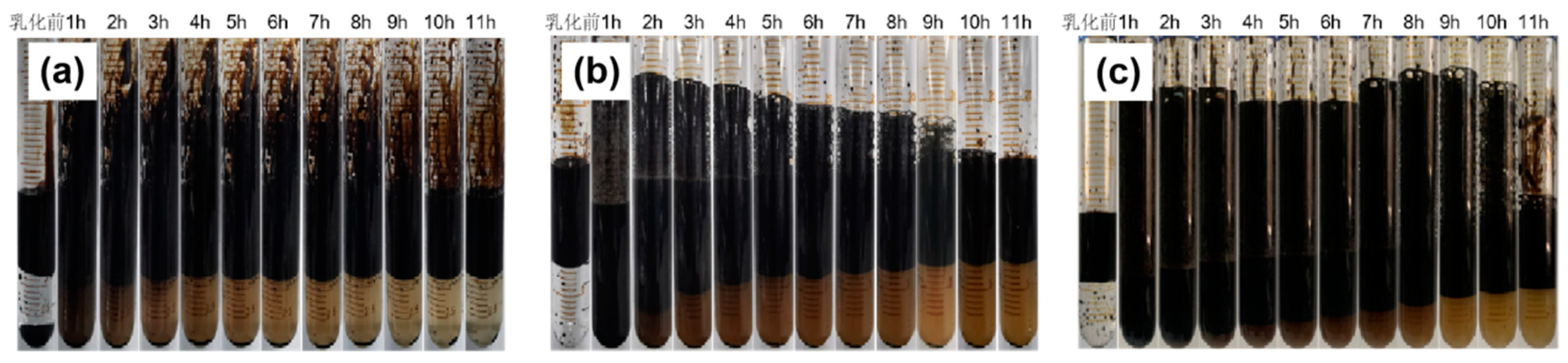
Figure 5.
Micro-effect of oil displacement by injecting three different emulsion stability compound systems into heterogeneous model: (a) the 3:1 blended system of branched-chain betaine and nonionic surfactants; (b) the 3:2 blended system of branched-chain betaine and nonionic surfactants; (c) the 1:1 blended system of branched-chain betaine and nonionic surfactants.
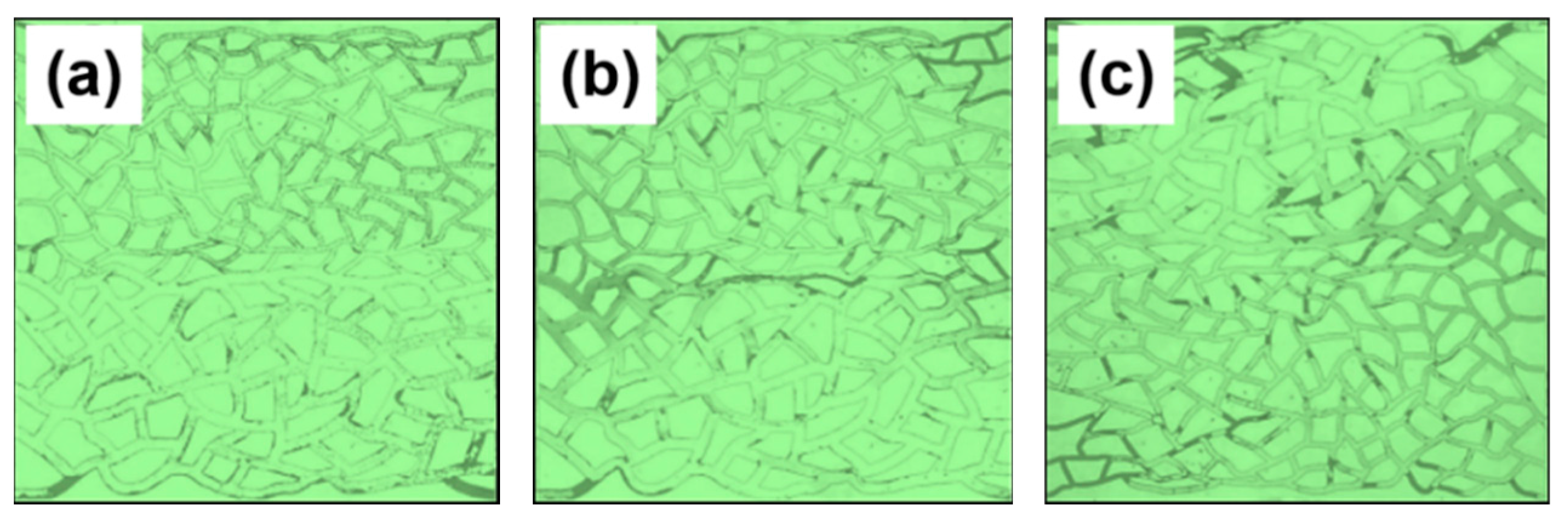
Figure 6.
Residual oil comparison diagram of three different emulsion stability compound systems injected into heterogeneous model.
Figure 6.
Residual oil comparison diagram of three different emulsion stability compound systems injected into heterogeneous model.
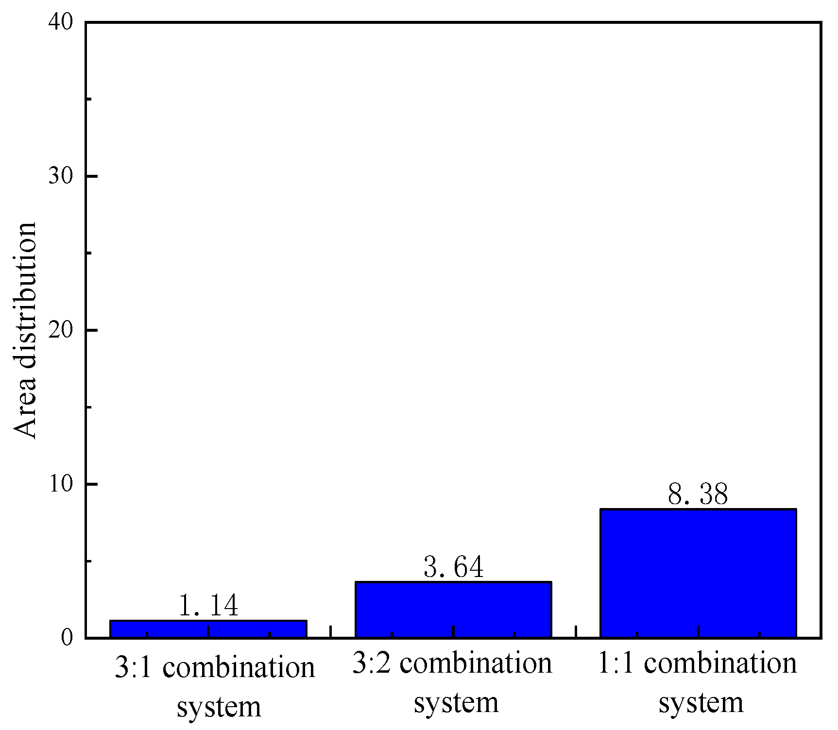
Figure 8.
Pressure changes of three different emulsion stability complex systems in the same injection experiment of two permeability cores.
Figure 8.
Pressure changes of three different emulsion stability complex systems in the same injection experiment of two permeability cores.
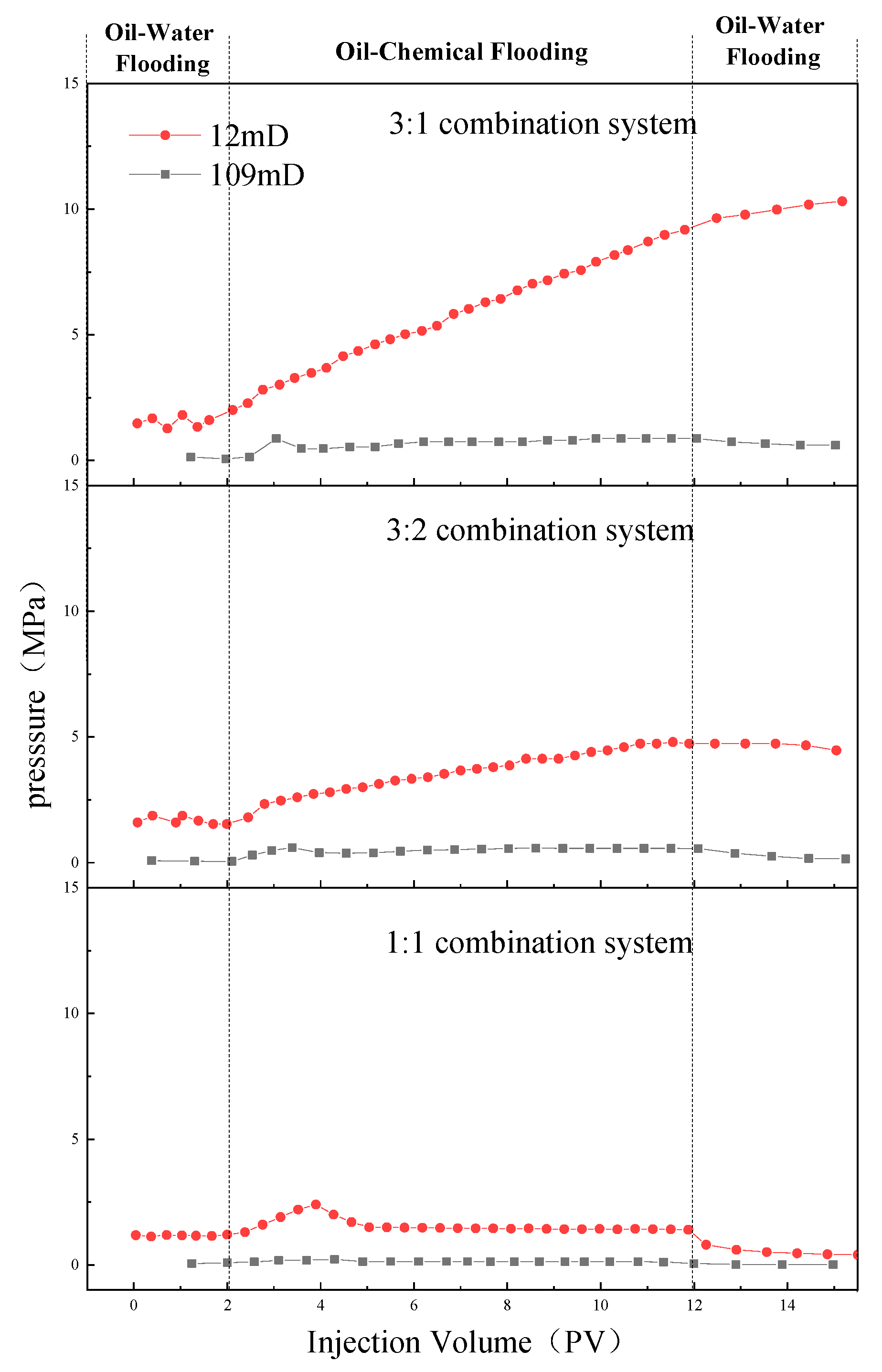
Figure 9.
Comparison of injection pressure of three different emulsion stability complex systems in two permeability cores: (a) 109 × 10 -3μm -2 permeability core; (b )12 × 10 -3μm -2 permeability core.
Figure 9.
Comparison of injection pressure of three different emulsion stability complex systems in two permeability cores: (a) 109 × 10 -3μm -2 permeability core; (b )12 × 10 -3μm -2 permeability core.
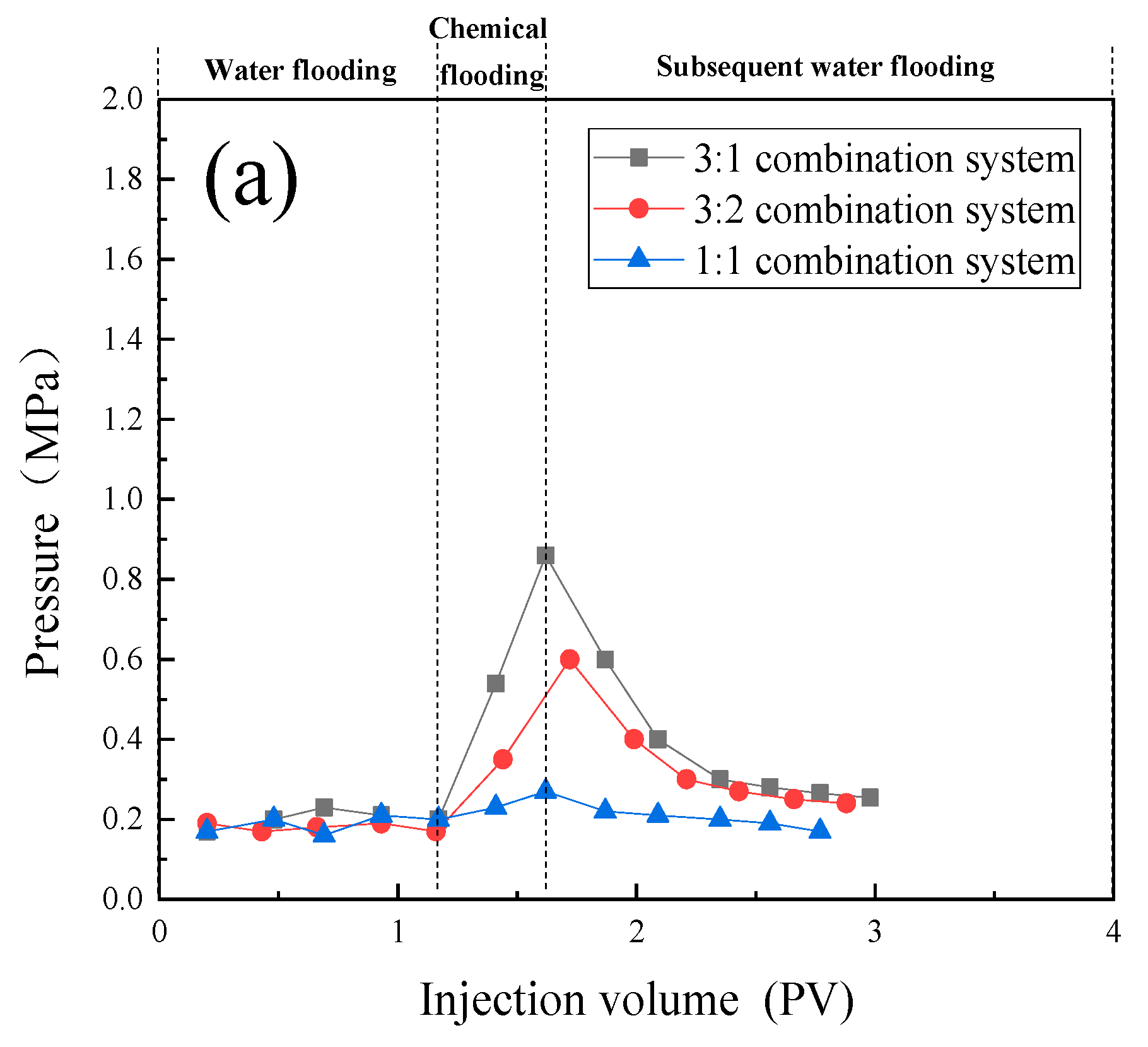
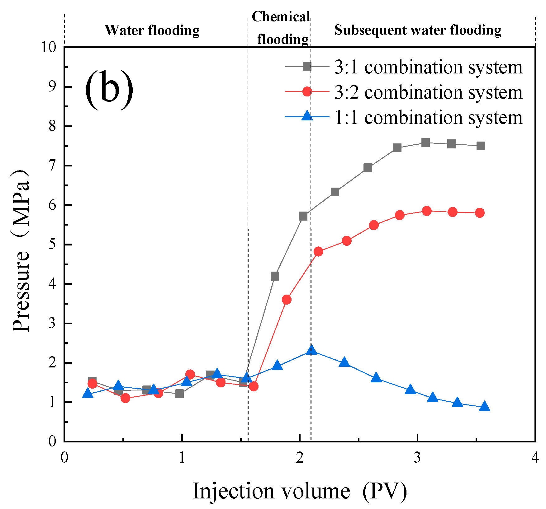
Figure 10.
Data comparison diagram of three injection modes for 180 ×10 -3μm -2 + 18 × 10 -3μm -2 parallel cores: (a) Pressure contrast diagram; (b) Comparison chart of shunt rate.
Figure 10.
Data comparison diagram of three injection modes for 180 ×10 -3μm -2 + 18 × 10 -3μm -2 parallel cores: (a) Pressure contrast diagram; (b) Comparison chart of shunt rate.
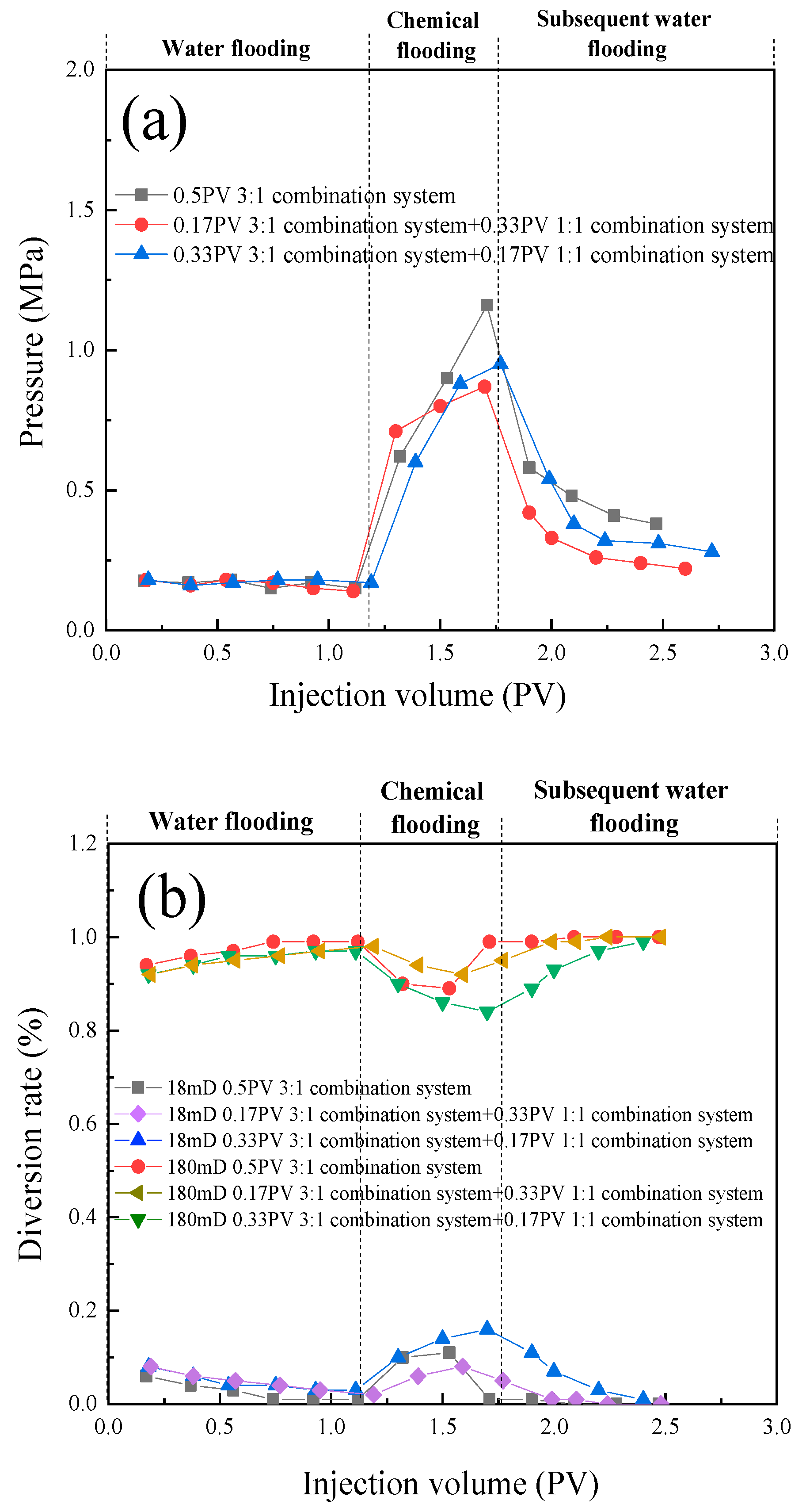
Figure 11.
Data comparison diagram of three injection modes for 20 ×10 -3μm -2 + 2 ×10 -3μm -2 parallel cores: (a) Pressure contrast diagram; (b) Comparison chart of shunt rate.
Figure 11.
Data comparison diagram of three injection modes for 20 ×10 -3μm -2 + 2 ×10 -3μm -2 parallel cores: (a) Pressure contrast diagram; (b) Comparison chart of shunt rate.
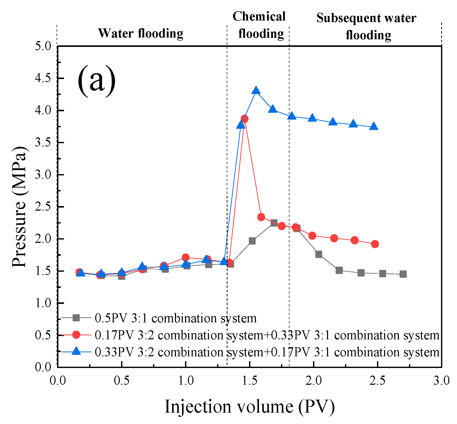
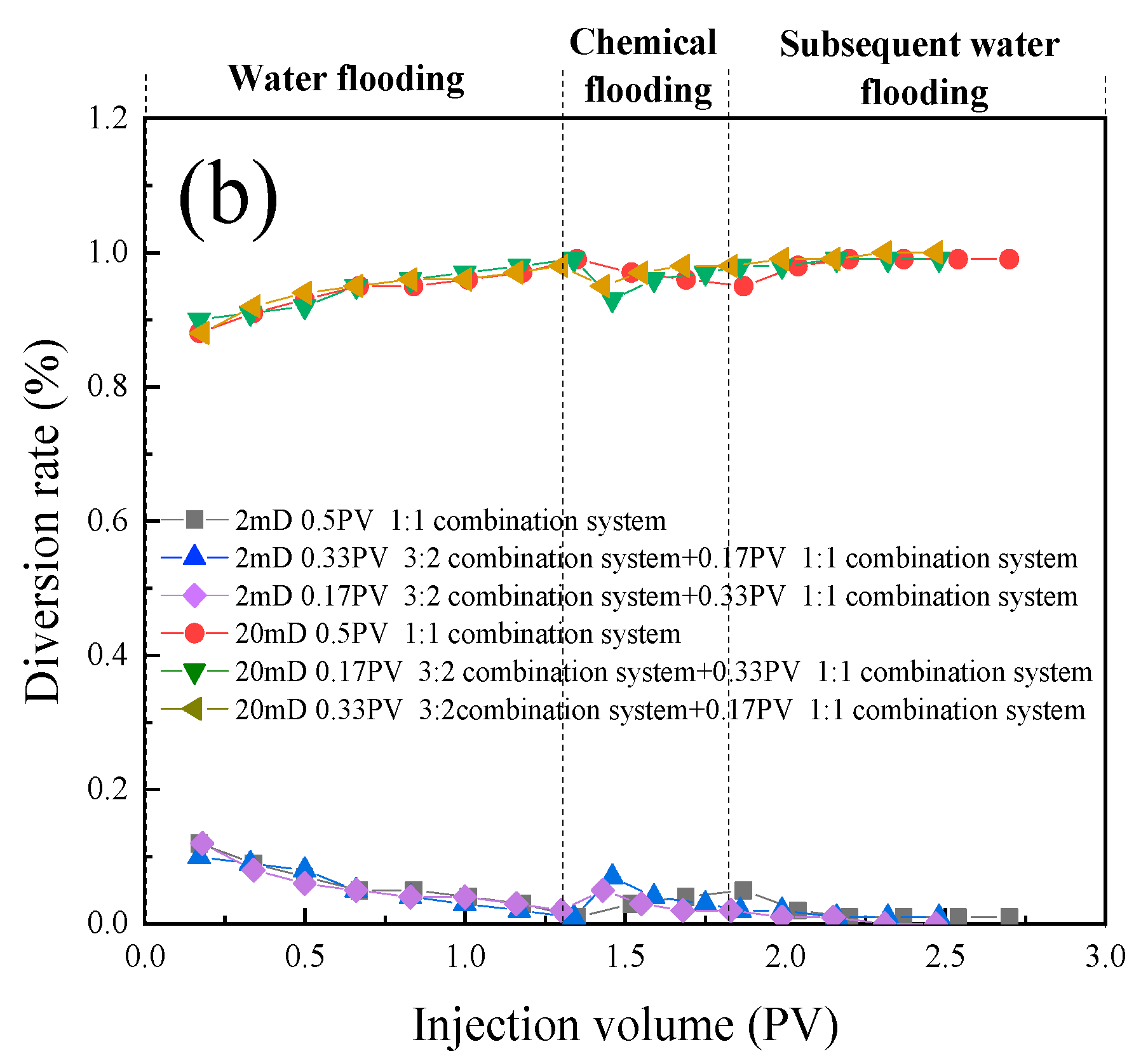
Figure 15.
Connection method of in-situ emulsion migration and migration performance research device. 1-Constant speed pump; 2-Piston container (containing chemical flooding system solution); 3-Piston container (containing water); 4-Piston container (containing experimental oil); 5-Valve (vent valve); 6-Pressure transducer; 7-Core; 8-Valve; 9-Pipes and power lines.
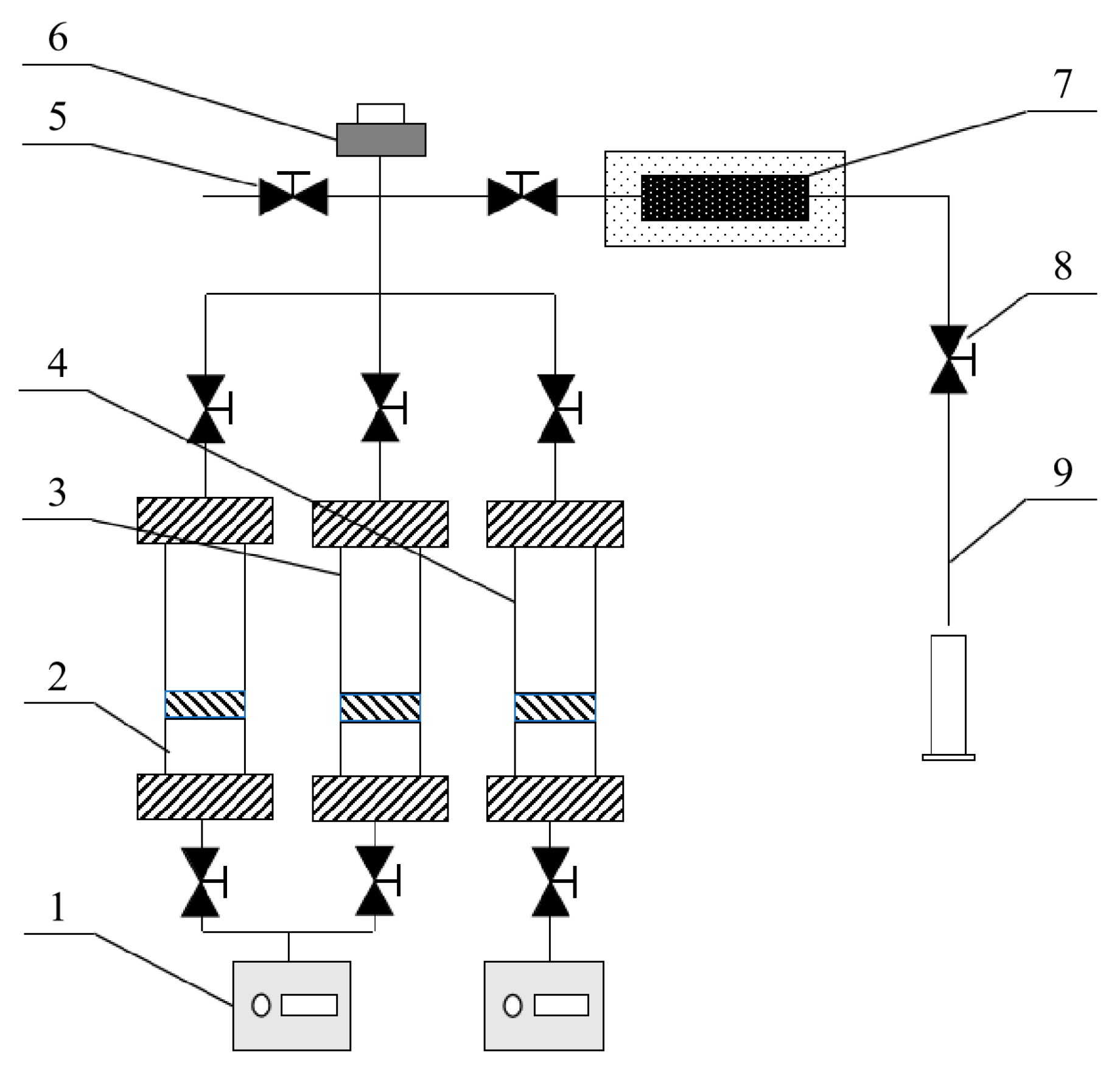
Figure 16.
Experimental flow chart. 1-Constant speed pump; 2-Piston container (containing chemical flooding system solution); 3-Piston container (containing water); 4-Piston container (containing experimental oil); 5-Constant temperature oven; 6-Control system pressure sensor; 7-Data acquisition system; 8-Core; 9-Valve.
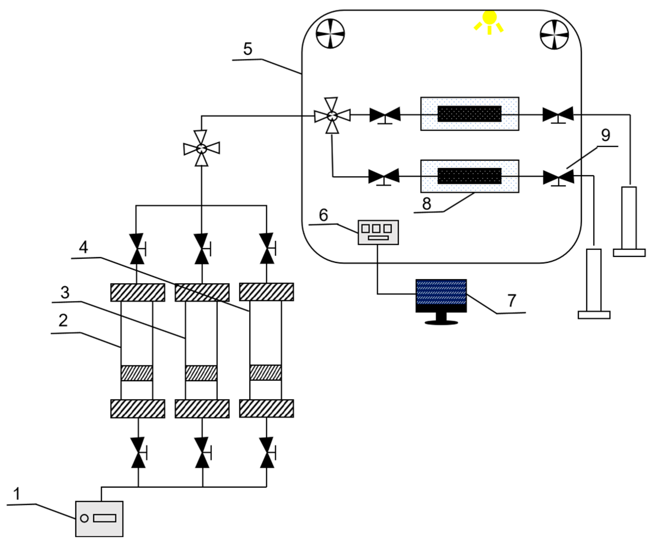

Table 1.
Oil displacement efficiency data of three different emulsion stability compound systems in two permeability cores.
Table 1.
Oil displacement efficiency data of three different emulsion stability compound systems in two permeability cores.
| Type of injected chemicals | Gas permeability (10 -3μm -2) |
Porosity (%) |
Water flooding recovery factor (%) |
Chemical flooding recovery factor (%) |
Total recovery factor (%) |
|---|---|---|---|---|---|
| 3:1 combination system | 109 | 18.1 | 64.00 | 17.33 | 81.33 |
| 3:2 combination system | 109 | 18.2 | 62.67 | 10.31 | 72.97 |
| 1:1 combination system | 109 | 18.15 | 64.13 | 3.57 | 67.7 |
| 3:1 combination system | 12 | 17.1 | 36.29 | 3.23 | 39.52 |
| 3:2 combination system | 12 | 17.5 | 34.68 | 7.26 | 41.94 |
| 1:1 combination system | 12 | 17.95 | 35.48 | 8.87 | 44.35 |
Table 2.
Experimental results of oil displacement in parallel cores under different injection methods.
Table 2.
Experimental results of oil displacement in parallel cores under different injection methods.
| Injection mode | Permeability (10 -3μm -2) |
Porosity (%) |
Water drive recovery ratio (%) |
Chemical flooding recovery factor (%) |
Total recovery factor (%) |
|---|---|---|---|---|---|
| Only inject a 3:1 combination system. | 180 | 23.4 | 63.1 | 20.34 | 83.45 |
| 18 | 15.3 | 9.63 | 2.04 | 11.67 | |
| Sequential injection 1 (inject the 0.17PV 3:1 combination system first., then inject the 0.33PV 1:1 combination system) | 180 | 22.9 | 65.45 | 15.95 | 81.4 |
| 18 | 15.2 | 14 | 5.45 | 19.45 | |
| Sequential injection 2 (inject the 0.33PV 3:1 combination system first., then inject the 0.17PV 1:1 combination system) | 180 | 23.6 | 62.91 | 19.21 | 82.12 |
| 18 | 15.1 | 13.64 | 9.09 | 22.73 | |
| Only inject a system 3 | 20 | 17.95 | 46.67 | 11.67 | 58.33 |
| 2 | 10.9 | 8.24 | 5.47 | 13.71 | |
| Sequential injection 1 (inject the 0.17PV 3:2 combination system first., then inject the 0.33PV 1:1 combination system) | 20 | 17.5 | 49.23 | 13.85 | 63.08 |
| 2 | 10.8 | 8.33 | 2.78 | 11.11 | |
| Sequential injection 2 (inject the 0.33PV 3:2 combination system first., then inject the 0.17PV 1:1 combination system.) | 20 | 17.65 | 48.33 | 8.33 | 56.67 |
| 2 | 10.2 | 8.72 | 1.18 | 9.89 |
Table 3.
Composition of the formation brine (mg/L).
| Na ++K + | Ca 2+ | Mg 2+ | Cl - | SO4 2- | HCO 3- | Total dissolved salinity |
|---|---|---|---|---|---|---|
| 53574.06 | 1766.168 | 919.1179 | 87071.7 | 1444.128 | 490.7045 | 145265.9 |
Table 4.
Experimental scheme for strength optimization of in-situ emulsification system.
| Injection mode | Core permeability |
|---|---|
| 0.5PV 3:1 combination system | 109 × 10 -3μm -2 |
| 0.5PV 3:2 combination system | 109 × 10 -3μm -2 |
| 0.5PV 1:1 combination system | 109 × 10 -3μm -2 |
| 0.5PV 3:1 combination system | 12 × 10 -3μm -2 |
| 0.5PV 3:2 combination system | 12 × 10 -3μm -2 |
| 0.5PV 1:1 combination system | 12 × 10 -3μm -2 |
Table 5.
Experimental scheme of double-tube parallel injection mode.
| Injection mode and system | Gas permeability |
|---|---|
| Only inject a 3:1 combination system. | 180 × 10 -3μm -2 |
| 18 × 10 -3μm -2 | |
| Sequential injection 1 (inject the 0.17PV 3:1 combination system first., then inject the 0.33PV 1:1 combination system) | 180 × 10 -3μm -2 |
| 18 × 10 -3μm -2 | |
| Sequential injection 2 (inject the 0.33PV 3:1 combination system first., then inject the 0.17PV 1:1 combination system) | 180 × 10 -3μm -2 |
| 18 × 10 -3μm -2 | |
| Only inject a 1:1 combination system | 20 × 10 -3μm -2 |
| 2 × 10 -3μm -2 | |
| Sequential injection 1 (inject the 0.17PV 3:2 combination system first., then inject the 0.33PV 1:1 combination system) | 20 × 10 -3μm -2 |
| 2 × 10 -3μm -2 | |
| Sequential injection 2 (inject the 0.33PV 3:2 combination system first., then inject the 0.17PV 1:1 combination system.) | 20 × 10 -3μm -2 |
| 2 × 10 -3μm -2 |
Disclaimer/Publisher’s Note: The statements, opinions and data contained in all publications are solely those of the individual author(s) and contributor(s) and not of MDPI and/or the editor(s). MDPI and/or the editor(s) disclaim responsibility for any injury to people or property resulting from any ideas, methods, instructions or products referred to in the content. |
© 2024 by the authors. Licensee MDPI, Basel, Switzerland. This article is an open access article distributed under the terms and conditions of the Creative Commons Attribution (CC BY) license (http://creativecommons.org/licenses/by/4.0/).
Copyright: This open access article is published under a Creative Commons CC BY 4.0 license, which permit the free download, distribution, and reuse, provided that the author and preprint are cited in any reuse.


