1. Introduction
Intraocular lenses (IOLs) are artificial lenses that play a crucial role in restoring vision for individual patients undergoing cataract surgery or seeking correction for refractive errors such as myopia, hyperopia, astigmatism, and presbyopia. Cataracts are a common eye condition that causes the eye’s natural lens to become cloudy, leading to blurred vision [
1]. During cataract surgery, the natural crystalline lens is broken up and removed through small incisions, followed by the insertion of an IOL into the capsular bag. IOLs are typically made from materials such as Acrylic, polymethyl methacrylate (PMMA) or silicone, adhering to strict FDA or similar biocompatibility standards [
2,
3]. Some IOLs may also have special coatings to reduce the risk of complications [
4,
5].
Following cataract surgery, patients often face challenges in choosing between distance and near vision correction, leading to reliance on spectacles [
6,
7]. Although toric [
8], multifocal [
9] and accommodative IOLs have been developed to address these challenges, achieving perfect vision remains intangible despite advancements in IOL technology. Another common issue following cataract surgery is the posterior capsule opacification (PCO), also known as secondary cataract. While the conventional treatment for PCO involves Nd:YAG laser capsulotomy, it is associated with complications like IOL damage, macular edema, increased intraocular pressure, and a higher risk of retinal detachment [
10,
11]. As an alternative to treatment, extensive research has explored the role of IOL surface modifications in reducing PCO incidence. Surface modified IOLs aim to prevent Lens Epithelial Cells (LECs) migration to the centre of the posterior capsule and enhance biocompatibility [
12]. While pre-operative measurement of corneal spherical aberration aids in selecting suitable IOLs [
13], even the best available lens may not fully meet each patient’s unique needs. To address this, the focus is on developing IOLs that integrate comprehensive corneal wavefront data, enabling the creation of fully customized IOL surfaces tailored to individual patient requirements, thus offering personalized vision correction solutions beyond standard lenses.
Laser technology has been widely utilized in various technological, industrial and medical fields for material processing purposes over the course of many years [
14,
15,
16,
17]. It finds applications in ablating, drilling, cutting, and other material modifications achieved by focusing concentrated laser energy onto the target material. The advantages of laser processing, such as reduced heat-affected zones, speed, versatility, and environmental considerations, make it stand out among alternative methods as provide also rapid prototyping and customisable solutions. The available lasers cover a spectrum of pulse durations, from continuous wave (CW) operation to nanosecond (ns), picoseconds (ps), and femtosecond (fs) pulses, and also at various wavelengths from ultraviolet to infrared band. Many studies have been performed into the physics of ultrashort pulse laser-matter interaction, emphasizing the differences in ablation mechanisms between short and ultra-short pulses [
18,
19,
20,
21]. The utilization of laser ablation by femtosecond lasers has been previously studied as an approach for patterning and shaping IOLs [
22,
23,
24]. The primary goal was to provide ophthalmologists with a tool for tailoring IOL patterns to suit the specific needs of individual patients using laser technology.
In this work, the laser ablation process was employed to create processed areas on the curved surface of commercially available IOLs. Two types of IOLs were considered: non-flexible PMMA lenses and flexible Acrylic lenses. The primary objective is to produce uniform and consistent modification of the IOL’s surface. By creating a homogeneous processed area, the IOLs are more likely to exhibit consistent optical properties and characteristics, which is important for achieving predictable and reliable visual functionality for patients who undergo cataract surgery and have these IOLs implanted. We employed three types of lasers: a femtosecond laser, a nanosecond laser, and a continuous wave diode laser, with very different characteristics, covering a wide range of laser sources in this study. Specifically, the femtosecond laser system emitted 370 fs pulses and operated at a wavelength of 1064 nm. The nanosecond laser system operated at 355 nm with 5 ns pulse duration. The CW diode laser operated at a wavelength of 405 nm. Firstly, ablated areas were systematically produced on the surface of both IOLs using the femtosecond laser. Additionally, a detailed study was conducted to determine the optimal laser parameters for producing spot patterns with desired characteristics, involving both the CW diode and nanosecond laser. Overall, the experiments aimed at understanding the effects of laser ablation of various types of lasers on different IOLs and to optimize the laser parameters for achieving uniform and consistent modifications on the IOL surfaces, thus identifying suitable laser patterning approaches potentially compatible with highly accurate IOL modification needed. The study was supported also with Raman spectroscopy for the identification of possible alterations of optical and material properties of laser processed IOLs which is important element for their usability.
2. Materials and Methods
2.1. IOLs
Two kinds of IOLs were used for laser processing. First, the PMMA lens (Hanita lenses, Spheric IOL, model: Balance), which is constructed from polymethyl methacrylate with refractive index n=1.49. Second, the flexible Acrylic lens (Alcon Inc, Acrysof® Aspheric IOL, model: SA60WF), which is composed of a hydrophobic Acrylate/Methacrylate Copolymer material with refractive index n=1.55. Both of these IOLs are designed for prosterior chamber implantation, include a UV radiation filter, have a lens power of +21.5, an optic diameter of 6 mm, and an overall length of 12.5 mm and 13 mm, respectively.
2.2. IOLs Characterization
Optical transmission spectra were obtained by means of a UV-VIS-NIR spectrophotometer (PEAK Instruments, C-7200). The surface morphology of the laser-patterned samples was examined via a JSM-7600F Schottky Field Emission Scanning Electron Microscope by JEOL (Tokyo, JP) operating at 10 kV to 15 kV. Various magnifications were employed during the SEM analysis, ranging from ×100 to ×10000. The samples were attached to the sample holder with conductive copper tape and coated with gold/platinum by using the SC7620 Mini Sputter Coater/Glow Discharge System by Quorum (East Sussex, UK), to enhance their conductivity and reduce charging effects during imaging. Moreover, optical images of the patterned areas in top view were obtained via an optical microscope (BRESSER Science, ADL 601 P), equipped with a micro-camera. The surface topography analysis was performed with a Surface Profilometer (KLA-Tencor, Alpha-Step IQ), a stylus-based step profiler. The assessment of microstructural and chemical modifications in laser-treated areas was conducted using regular and confocal micro-Raman spectroscopy (Renishaw, inVia Reflex Raman microscope). The spectra were measured using an argon ion (Ar+) laser for excitation at 514.5 nm. Both a ×20 (NA 0.40) and a ×100 (NA 0.85) objective lens were employed, offering a nominal spatial resolution (0.61*λ/N.A.) of ca. 785 nm and 370 nm, respectively.
2.3. Femtosecond Laser Micromachining Setup
An ultra-short fiber-based laser system was employed (Fianium, HE-1060-1uJ-fs, Southampton, UK), which emits laser pulses with a duration of 370 fs at a wavelength of 1064 nm. The laser has maximum pulse energy of 1 μJ, and variable repetition rate up to 1 MHz. The power values were monitored using a thermal power sensor (Thorlabs, S302C). The laser beam was focused onto the IOL surface using a ×20 achromatic standard objective lens with a numerical aperture (NA) of 0.4 (Edmund Optics). The beam spot size was ~3.6 μm as calculated by the equation:
where
is the beam quality (1.2),
λ is the laser wavelength,
f is the focal length of the lens (8.3 mm) and
is the diameter of the laser beam before the lens (3.8 mm). The IOL samples were placed on
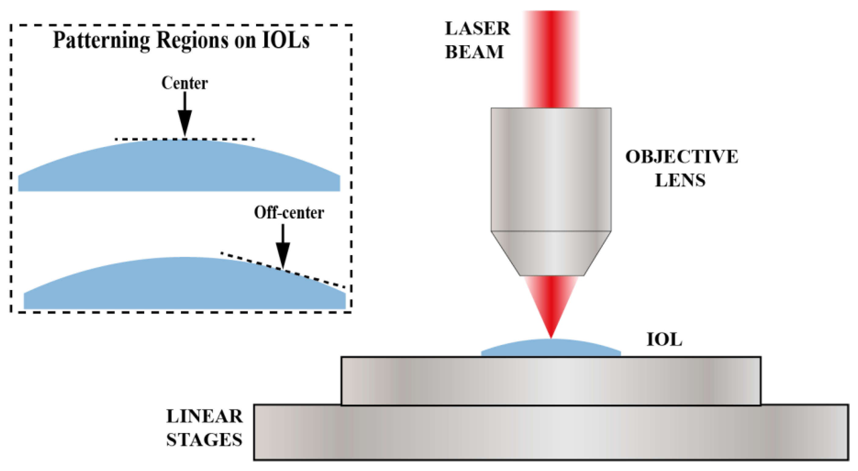
X-Y motorized linear stages with nominal resolution of 1nm (Smaract, CLS-92152), allowing for precise movement and positioning (
Figure 1). This setup was designed to facilitate controlled and precise laser-induced modifications on the IOLs surface. A CMOS monochrome camera (Teledyne Dalsa, Genie Nano M640) was used for imaging and determining the laser focus position on the IOLs.
2.4. Nanosecond Laser Setup
A pulsed Q-switched Nd:YAG laser system was employed (Litron Lasers, Nano S 130-10), operating at the third harmonic wavelength of 355 nm, with a pulse duration of 5 ns, a repetition rate of 10 Hz, and operated at a stable pulse energy of 7.2 mJ. The laser beam was focused utilizing a plano-convex lens with a focal length of 200 mm, resulting in an incident fluence of 1.1 J/cm
2. As illustrated in
Figure 1, the samples were positioned on a motorized platform, enabling movement along both the
X-Y axes.
2.5. CW Diode Laser Micromachining Setup
A low cost CW diode laser was employed (4PICO, HSLU) with a wavelength of 405 nm, producing a collimated laser beam with maximum power 36 mW. The optical power of the laser was measured with a photodiode power sensor (Thorlabs, S120C). The laser operated either with an external trigger mode for multi-shot experiments or a continuous mode for line ablation. The beam was focused onto the IOL surface using a high-magnification objective lens with NA=0.90 (Corning Tropel) and the beam spot size was approximately 300 nm. The IOL samples were placed vertically on the X-Y motorized linear stages (Smaract, CLS-92152) and a CMOS monochrome camera (Teledyne Dalsa, Genie Nano M2020) was used for maintaining precise focusing during the experiments. Due to the specific optical arrangement the sample in the diode writing setup was moving only in one axial direction in this setup.
3. Results
3.1. Optical Properties
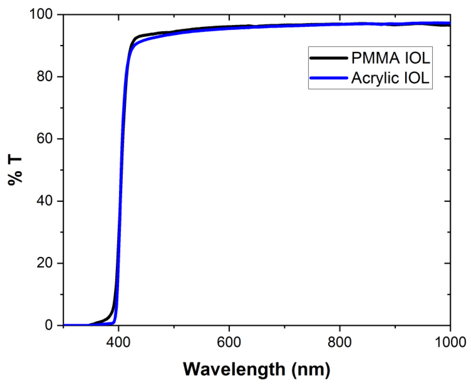
Optical transmission spectra were measured between 300 nm and 1000 nm for the two kinds of IOLs employed here (
Figure 2). We observe an absorption cut-off wavelength at 400 nm for both lenses. Therefore, the CW laser with a wavelength of 405 nm and the 355 nm of the nanosecond laser are strongly absorbed by the lenses. Even though the wavelength of the femtosecond laser (1064 nm) falls within the transparent regime of these lenses, tight focusing of the laser beam, and multiphoton absorption in the fs laser case, achieves efficient laser patterning on the surface of the IOLs, as demonstrated in the following sections.
3.2. Fabrication and Characterization of Femtosecond Laser-Induced Micro-Patterns
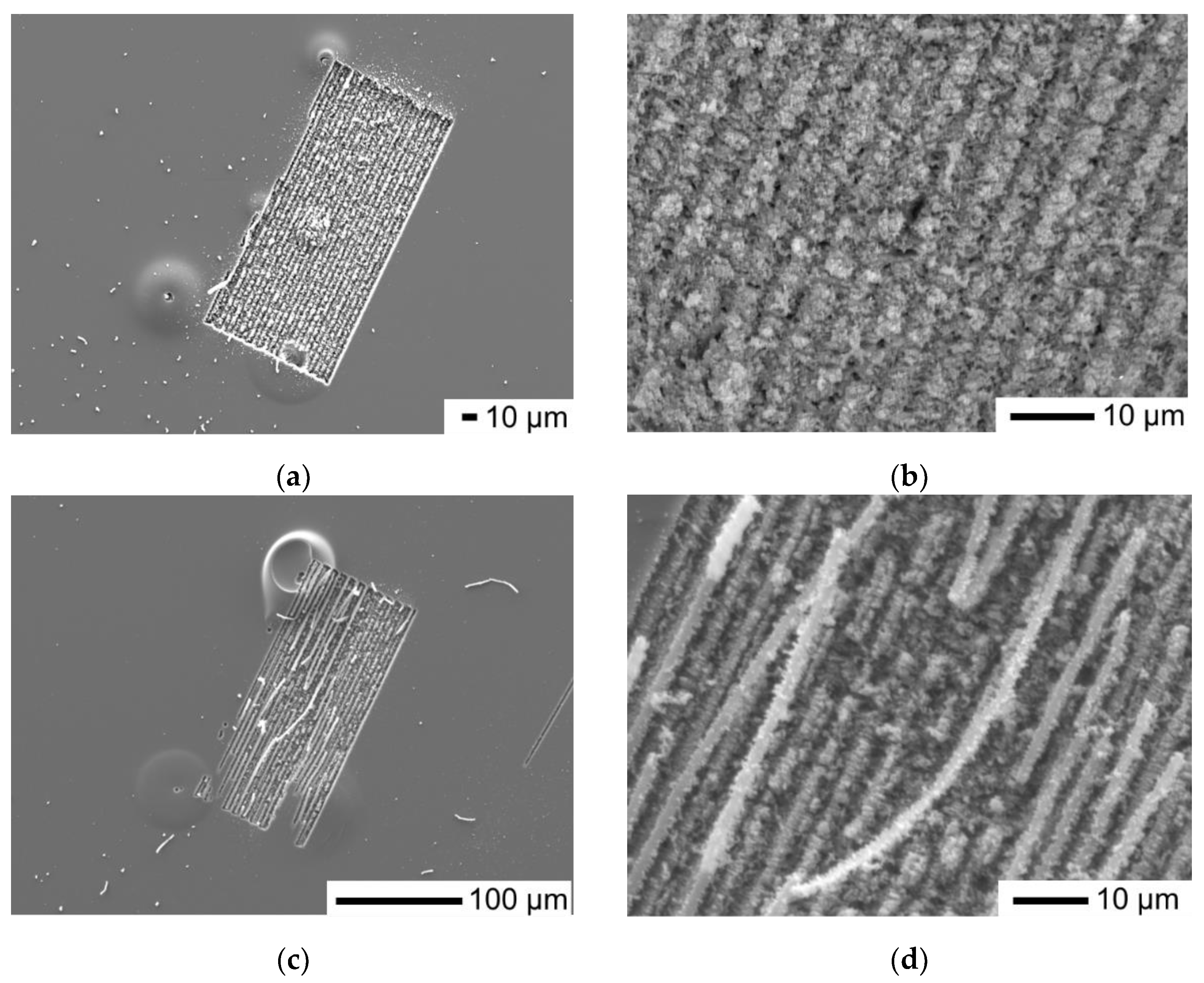
A homogenous ablated area was formed on the central region of the PMMA IOL, as shown in
Figure 3a,b, following irradiation with a pulse energy of 0.8 μJ and repetition rate 100 kHz. Additionally, another ablated area was formed on the off-centered, curved side of the lens, as shown in
Figure 3c,d. These areas covered a rectangular area of 100 μm in width and 200 μm in length and were created with a continuous scanning process without refocusing the objective lens. The lateral separation between each parallel scan was set at 4 μm, a value that approaches the theoretical beam spot size of the lens (3.6 μm). The intention was to achieve an effective overlap between parallel scans for a uniformly modified surface. For each line scan, the translation was set at 200 μm and the scanning speed at 10 μm/s. The ablation process on the PMMA IOLs results in the formation of a symmetrical region around the focal spot overall displaying the characteristic roughness and porosity of a PMMA laser ablated surface [
25,
26]. The laser processing parameters were selected in order to prevent excessive damage on the surface of the PMMA IOL.
It can be observed that when patterning at the off-centered, curved side of the IOL due to varying focus conditions there are residual threads of removed material, leading to incomplete ablation and increased surface roughness. However our findings highlight the critical influence of precise focus conditions on the patterning mechanism and the consistency of the ablation procedure. By further optimising the linear patterns overlap and the writing depth the surface uniformity and the roughness of the patterned area could be further improved where need in real applications.
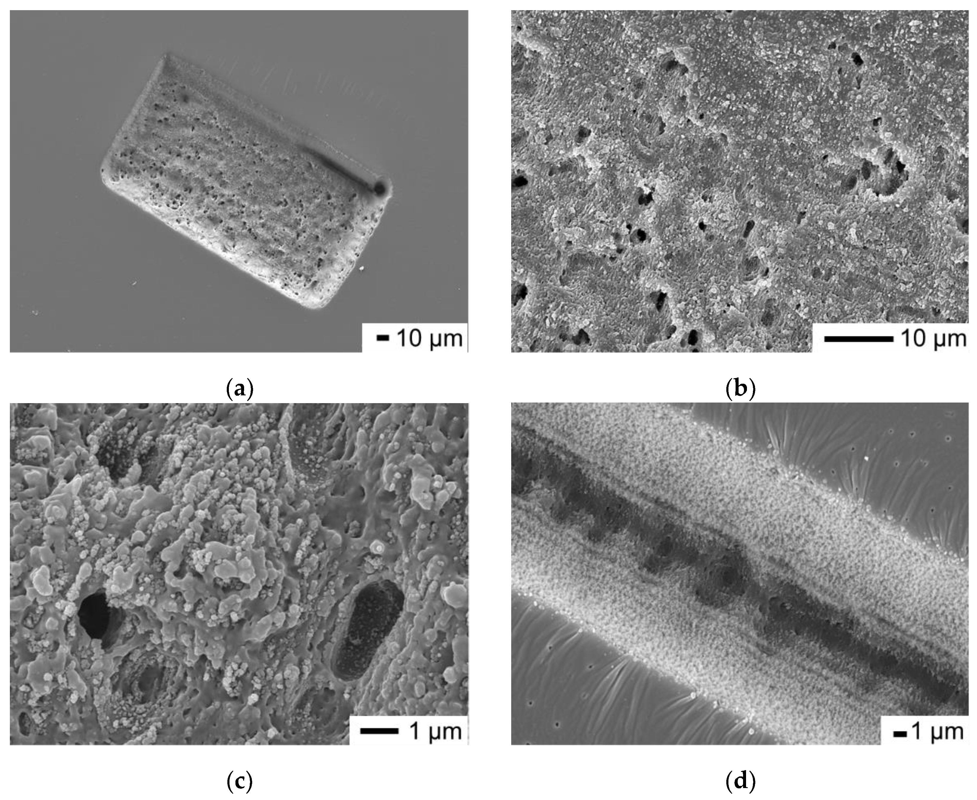
On the off-centered, curved side of the Acrylic IOL we again created a 100 μm in width and 200 μm in length rectangular area using exactly the same exposure conditions as those employed for the PMMA IOL. This process results in the creation of structured regions, as illustrated in
Figure 4a–c, which portray the ablated area at various magnifications. The SEM analysis reveals several notable features such as an expanded width in a single line scan, as presented in
Figure 4d, the presence of molten material, and the formation of micro cavities. The observed micron-sized cavities likely result from gas release during the thermal degradation of the Acrylic material. These findings strongly indicate localized thermal modification in the patterned area, representative of a photo-thermal ablation process. Although heat accumulation effects with femtosecond lasers typically manifest for repetition rates higher than 200 kHz or even 1 MHz [
27,
28], the response depends on the thermal properties of the target material. Properties including thermal diffusivity, melting point, and heat capacity, play a fundamental role in determining its response to the intense heat generated during laser ablation. For example, the thermal diffusivity of PMMA and other acrylics polymers can be influenced by the molecular weight or the presence of additives in the polymer [
29]. These factors can significantly affect the ablation process, potentially altering the material’s behaviour under laser exposure.
The peak laser fluence is determined, considering a Gaussian beam, using the equation:
where
represents the pulse energy set at 0.8 μJ and d is the focused beam diameter. The peak fluence used for the micromachined areas was 8 J/cm
2. This value exceeds the ablation threshold for both PMMA and Acrylic materials. We also determine the effective number of pulses delivered per surface area, calculated as 40 × 10
3 for both IOLs, utilizing the formula:
where RR represents the pulse repetition rate, d is the beam diameter, and s is the translating speed of the stage.
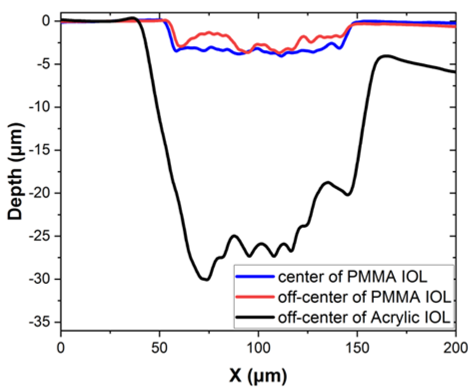
Following irradiation by the femtosecond laser, we performed depth measurements with the surface profilometer, along the short dimension of the ablated areas (100 μm in width), to evaluate the material modification and the precision in the laser-ablation process. As indicated in
Figure 5, the ablation depth for the PMMA IOL ranges from 3 to 3.5 μm in the area created at the center of the lens (blue line) and from 1 to 3 μm in the area located on the off-centered, curved side of the lens (red line). In contrast, for the Acrylic IOL, the measurement of the modified area located on the off-centered, curved side of the lens (black line), exhibits a deeper ablation depth of 20 to 30 μm, as shown in
Figure 5. In the off-centered modified regions of the lenses, the surface exhibits non-uniform modification depth, indicating variations probably due to the different distance from the beam focus and the absence of refocusing during the irradiation process.
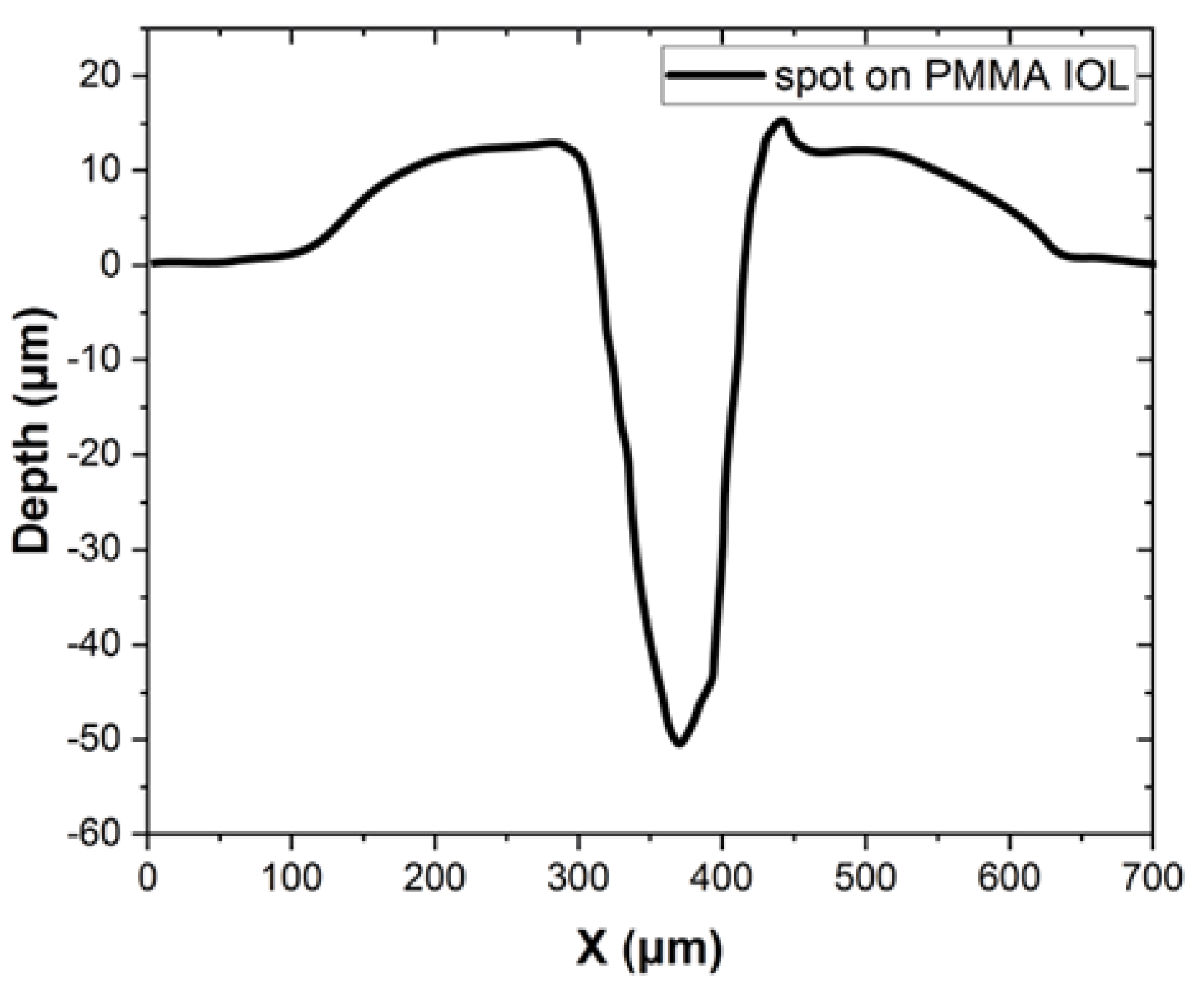
Further investigation into irradiation parameters with the femtosecond laser revealed that employing higher repetition rates, such as 1 MHz, in combination with the different materials under examination, resulted in a significant increase in ablation depth. This was evidenced by the observation of 50 μm deep and 50 μm wide ablation spots observed on PMMA IOLs, as shown in the measurements obtained with the surface profilometer in
Figure 6. This increase can be attributed to the higher energy delivered to the target material per unit time, resulting in more substantial material removal per laser pulse or over a given time. The higher energy levels or repetition rates impart greater momentum to the laser-induced plasma, leading to increased material ejection and, consequently, deeper ablation depths. Additionally, the scanning speed is another parameter affecting the ablation depth. This observation underscores the significant influence of laser writing parameters [
30] on the material processing characteristics, particularly in the context of laser ablation of IOLs for applications such as surface modification. Further exploration of different irradiation parameters could potentially lead to achieving similar modifications on Acrylic IOL as those achieved on PMMA IOL.
The above findings suggest that the employed infrared femtosecond laser can be efficiently used for patterning in both PMMA and Acrylic IOLs surface with very good repeatability and resolution due to the consistent response of the material. Various femtosecond lasers have been employed in the past. For example in [
22] a 800 nm fs laser with much higher pulse energy up to 200 μJ, but with low repetition rate of 5 kHz, was employed for writing linear structures with depths up to 5 μm. Also in [
23] a femtosecond laser at 520 nm with much lower pulse energy of 1 nJ was employed for IOL but with discontinuous line patterning due to thermal effects attributed to the very high repetition rate of 63 MHz.
In general, two distinct regimes of femtosecond laser writing or micromachining can be identified based on the pulse period relative to the time required for heat to diffuse away from the focal volume. The low-frequency regime with high energy pulses involves material modification by individual or low frequency pulses, while the high-frequency regime with low energy pulses involves cumulative thermal effects. These two distinct regimes are essentially represented in the aforementioned cases in references [
22] and [
23] previously discussed. The heat diffusion time (τ
heat) of the absorption volume in the material under investigation, is related to the thermal diffusivity (D) and the characteristic diffusion length (L), through the following equation [
31]:
The transition between these two regimes occurs at laser repetition frequencies defined as the inverse of τ
heat. In a previous work [
28] for the case of laser writing and patterning in glasses it was identified an intermediate regime of optimum laser writing and patterning conditions, by a fiber Yb-based laser emitting at 1030-1064 nm, with pulse energy ~1μJ, ~300 fs pulse duration and repetition rate ~1MHz. This laser provided by far the best laser writing performance in glass enabling fast processing with eliminated heat accumulation effects resulted in uniform structures, as in typical glasses the heat diffusion time is τ
heat ~1 μs and the transition should occur at around 1 MHz [
28]. Our results indicate that an analogous behaviour was observed in the patterning of polymer IOLs. For glasses the thermal diffusivity is around D~0.6 mm
2/s while for PMMA is roughly D~0.1 mm
2/s [
29]. Therefore, the τ
heat is estimated to be much slower (by a factor of ~6) in polymers compared to glasses, and the expected transition frequency should be correspondingly lower. This is in agreement with our findings, as the femtosecond system we employed (with the capability of tunable repetition rate between single pulse and 1 MHz) operated in this intermediate regime (100 kHz), which has been demonstrated to offer superior micromachining characteristics, providing enhanced patterning capabilities and flexibility. However, the exact identification of the intermediate regime was not possible as depends drastically on characteristics of polymers like the molecular weight, which was not known for the commercially used IOLs.
3.3. Nanosecond Laser Ablation of Acrylic IOLs
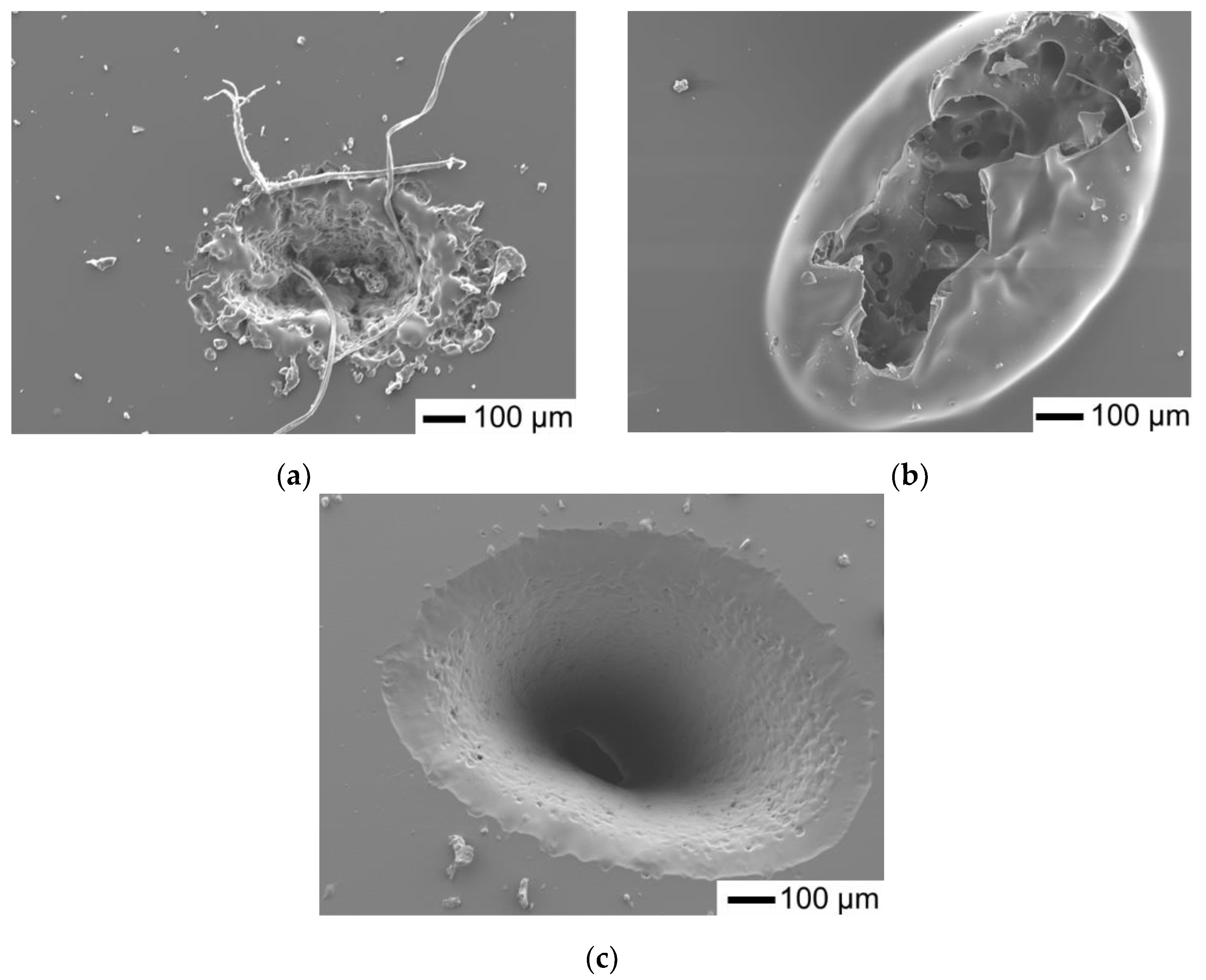
We conducted experiments involving the creation of ablated spots or craters on the surface of Acrylic IOLs using the nanosecond laser with different exposure times and pulse energy 7.2 mJ. This allows us to observe how the duration of exposure affects the dimensions and characteristics of the resulting craters. The SEM images of the ablated spots are shown in
Figure 7.
For the 30-second exposure, the crater dimensions are measured as 630 × 440 μm with resolidified debris around the edges (
Figure 7a). With an increase in exposure time to 1 min, the crater dimensions expand to 880 × 650 μm (
Figure 7b). Notably, in the case of the 1-min exposure, we observe a dome-like feature above the crater, which indicates a micro-explosion inside the bulk or beneath the surface of the IOL. This suggests that prolonged exposure to the nanosecond laser results in significant material disruption within the IOL. Subsequently, for the 6-min exposure, the crater dimensions further increase to 1030 × 740 μm, the ablation results in a well-formed crater but the ablation depth exceeds the IOL thickness which is ~500 μm penetrating the back side of the IOL (
Figure 7c). The elliptical pattern observed as evidenced by the dimensions of the ablated spots, indicates the spatial characteristics of the corresponding laser beam during the ablation process. This variation in crater dimensions and characteristics highlights the sensitivity of the nanosecond laser ablation process to exposure time, where although slow and relatively controllable in the regime of several minutes processing duration, with longer exposures can lead to more extensive material removal and potential structural changes within the IOL.
Comparing these results with those obtained with the femtosecond laser reveals interesting insights. The femtosecond laser ablation process typically yields finer and more precise ablation patterns due to its ultrafast pulse duration, high peak power, and suppressed thermal effects [
32,
33]. In contrast, nanosecond laser ablation tends to result in larger and less controlled ablation areas, as observed in these experiments. Additionally, the presence of an explosion-like patterning of material under the surface, as seen in the 1-min ns exposure, highlights a distinct effect of nanosecond laser ablation, attributed to increased thermal effects, not typically observed with femtosecond lasers.
3.4. CW Diode Laser Patterns
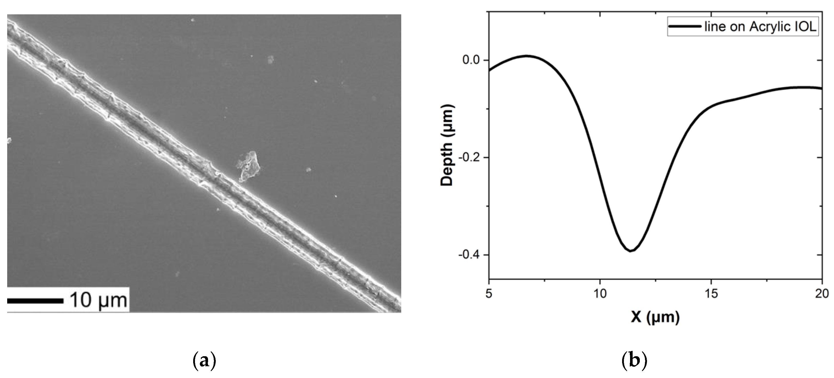
A series of patterning experiments were conducted also with CW-laser at 405-nm as it provides very different Laser characteristics compared to previous cases. However, due to specific optical arrangement and horizontal exposure configuration of the writing system the pattern generation was limited to a single line direction or stationary spot exposure. Specifically, for the Acrylic IOLs, the translation distance range was set to 900 μm, with a scanning speed of 1 μm/s, an order of magnitude smaller than the femtosecond setup. The power delivered on the surface was 10 mW, resulting in an intensity of 14 MW/cm². The final ablated line is 450 μm in length and 3.5 μm in width, as shown in
Figure 8a, mainly influenced by the IOL curvature and limited depth of focus of the objective lens. The depth of ablation for the line, as measured with the surface profilometer, is approximately 400 nm as shown in
Figure 8b. Considering the objective lens spot size of 300 nm and the observed line width of 3.5 μm thermal effects likely play a significant role in this process.
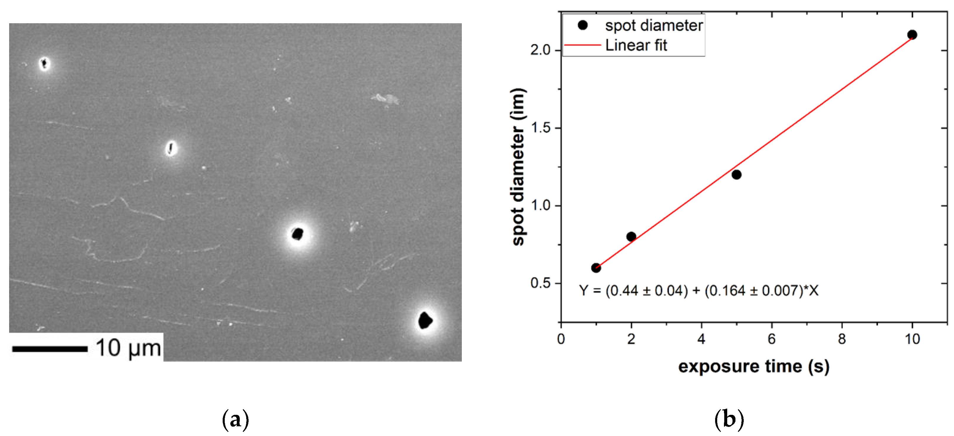
Additionally, we conducted experiments exposing a single point to varying durations of 1 s, 2 s, 5 s, and 10 s. These exposures resulted in ablated spots with crater dimensions of 0.6 μm, 0.8 μm, 1.2 μm, and 2.1 μm, respectively, as illustrated in
Figure 9a. The experimental results, showcasing a gradual increase in the ablated area, indicate a linear correlation between exposure time and the size of the ablated spot, as indicated in
Figure 9b, emphasizing the temporal dependence of laser ablation process on the IOLs.
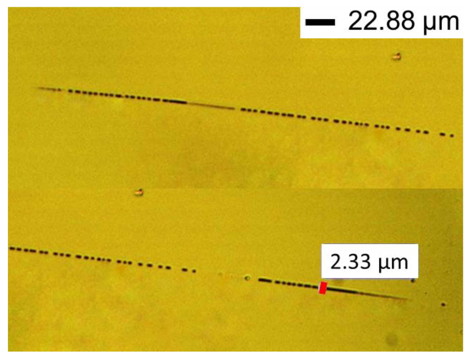
The use of the 405-nm CW diode laser for patterning the PMMA IOL demonstrates its capability for precise and controlled ablation, despite the limited patterning data we have obtained in this study. However, in several patterning experiments it was noticed that the exposed area was discontinuously patterned. This phenomenon can be partially attributed to the low exposure power for this material and the non-adaptive focusing of the beam when transferred in a non-uniform IOL with varying curvatures. However it can be also attributed to the fact that the processing occurs at thermal processing regime where accumulation of continuous laser radiation or discrete multiple pulses lead to increase of local temperature and modification of polymers properties. The same phenomenon has been described in femtosecond laser patterning in [
23]. Such discontinuous patterns are shown in the optical microscope image in
Figure 10. Due also to technical issues with the gold post-sputter coating process before the SEM characterization it was difficult to provide SEM images for the in- detail visualization of those discontinuous patterns. It should be stressed that this is the first demonstration of successful patterning of IOLs by a compact and low power CW diode laser which provides a considerable potential for low cost IOLs patterning, however further studies are required to address these challenges and optimize the process.
Τhe process with the CW laser differs significantly than the other two lasers, due to the differences in wavelength and energy delivery mechanism or the materials’ laser induced modification processes. While the nanosecond and femtosecond laser ablation processes rely on thermal or multiphoton ultrafast laser-matter interactions, respectively, the 405-nm laser ablation process could rely also on photochemical reactions. Consequently, the ablation characteristics, such as spot dimensions and material effects, may vary considerably between these different laser systems and wavelengths. Further comparative studies could provide deeper insights into the specific advantages and limitations of each ablation technique for applications in ophthalmology and other fields.
3.5. Microstructure and Chemical Composition
Following laser irradiation, the primary goal was to confirm that the physical and chemical properties of the IOLs are retained unaltered or at an acceptable degree, ensuring their suitability for ophthalmological use in patients. To verify this, micro-Raman measurements were conducted using the Ar+ 514.5 nm line for excitation. Care was taken to keep the laser power at a low level, to avoid laser induced modifications: ca. 275 μW for the ×20 lens and 45 μW for the ×100 lens. Both regular and confocal micro-Raman spectra were acquired in the wavenumber region 100-3200 cm-1. For the measurements with the ×20 lens, each spectrum corresponds to an acquisition time of 40 s for both IOLs, preceded by a bleaching time of 120 s: the reason for quenching the photoluminescence was to have an easier way to compare the Raman spectra of the polymer in the pristine and the laser-irradiated PMMA samples and thus detect possible irradiation-induced polymer modifications. To increase the possibility of probing a thinner surface layer of the sample, where the laser irradiation is expected to be maximal, with reduced interference from less irradiated areas lying deeper below the surface, we ran confocal measurements with the ×100 lens: the acquisition time was set at 40 s for PMMA IOLs and 120 s for Acrylic IOLs without bleaching, so as to have a direct way to compare with results from the literature.
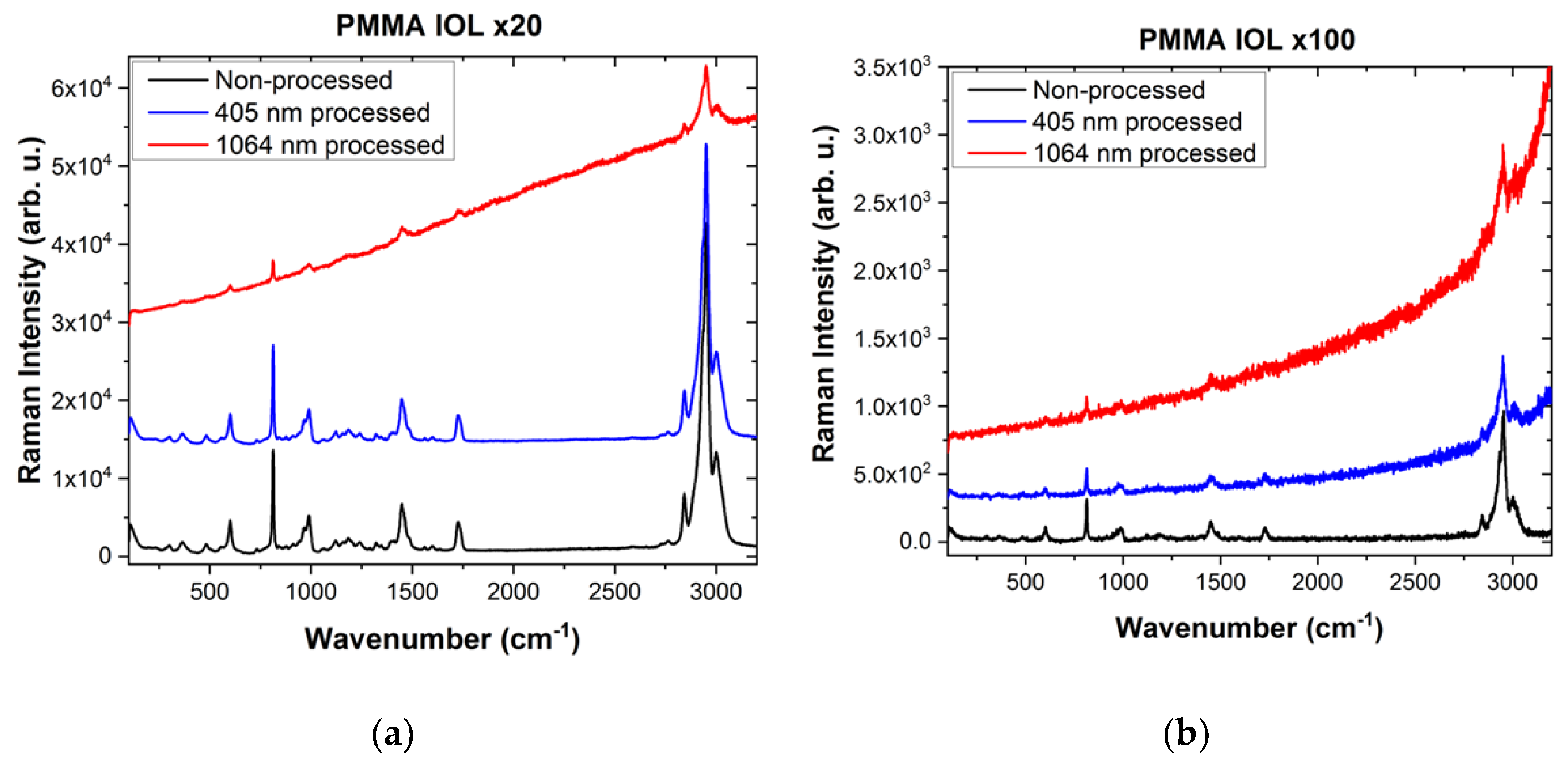
Raman spectra of the PMMA IOL before and after laser ablation with femtosecond 1064-nm and CW 405-nm are illustrated in
Figure 11. The Raman spectra exhibit sharp peaks and broad bands, consistent with those reported in the literature [
34,
35,
36]. Among the observed eight strongest Raman bands, the most prominent one is at 2951 cm
−1. This is assigned to the overlap of the symmetric C–H stretching vibration of O–CH
3 (methyl group forming part of the ether C–O–C chain) with the asymmetric C–H stretching vibration of α-CH
3 (methyl group attached to a backbone C) [
35]. The corresponding symmetric C–H stretching vibration of α-CH
3 is the shoulder seen at ca. 2885 cm
−1 (discernible only after sufficient magnification in the figure). The band at 3000 cm
−1 is the asymmetric C–H stretching vibration of O–CH
3. The 2843 cm
−1 is assigned to the CH
2 (methylene) symmetric C–H stretch; the CH
2 asymmetric C–H stretch is a shoulder at ca. 2935 cm
−1 (not discernible in the figure). The band at 1450 cm
−1 is the O–CH
3 symmetric bending vibration, while other type methylene or methyl bending vibrations are seen at lower intensity in the vicinity, as shoulders or broader bands. The C=O stretch is observed at 1725 cm
−1, the C–O–C symmetric stretch appears at ca. 813 cm
−1, while the symmetric C–C–O (the central C is the one with the carboxyl bond) stretch is observed at 600 cm
−1 [
34]. The symmetric CH
3 rocking modes form the doublet at 967 (α-CH
3) and 989 cm
−1 (O–CH
3).
In
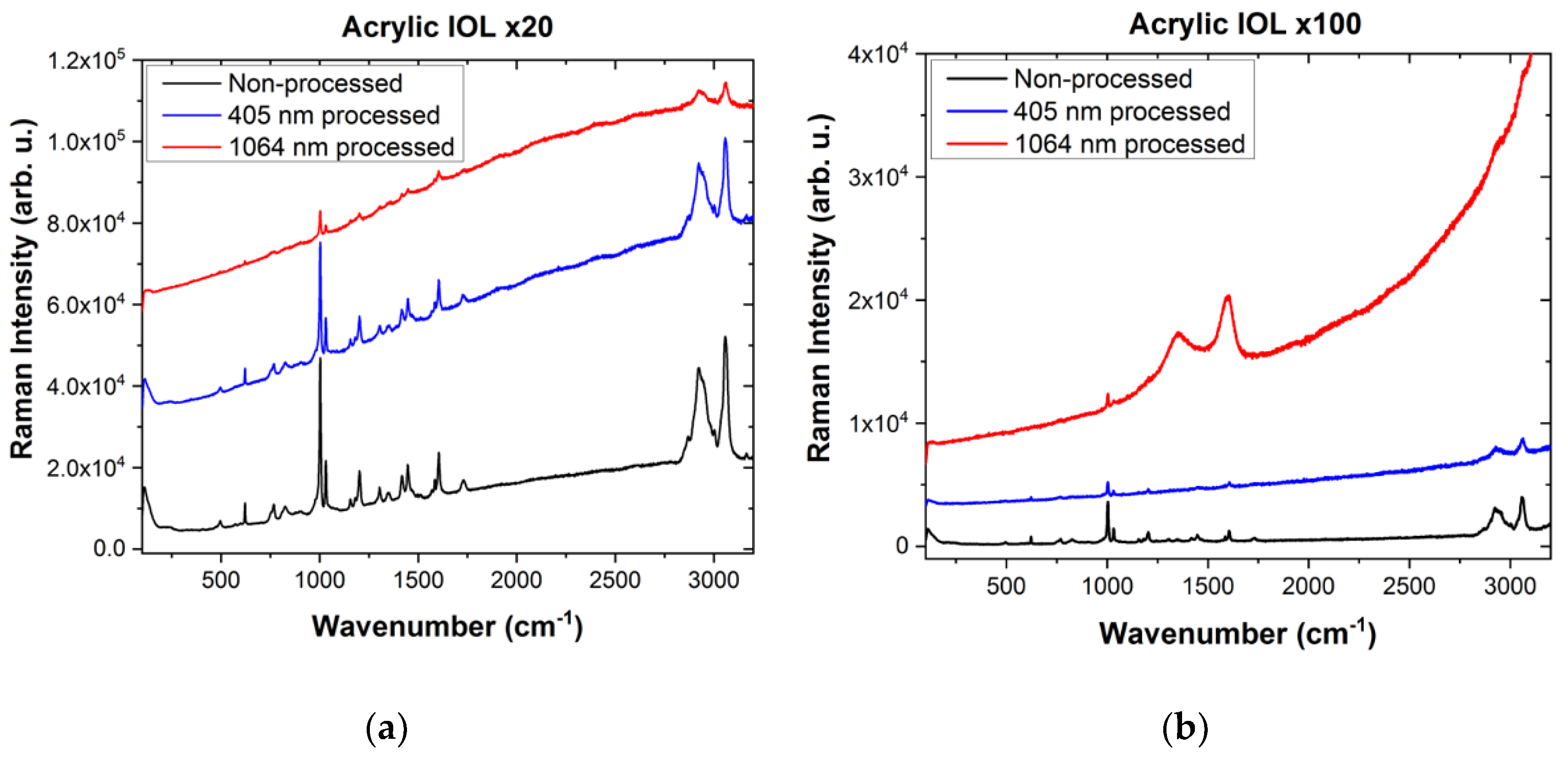
Figure 12, we present Raman spectra of the Acrylic IOL before and after laser ablation with femtosecond 1064-nm and CW 405-nm. The pristine IOL Raman spectrum is very similar to the Alcon (Acrysof) model MA60BM IOL hydrophobic acrylic material shown in [
37] or to the hydrophobic UV-photo-reactive polybenzylmethacrylate polymer (produced by Contateq, Eindhoven, The Netherlands) shown in [
23] or even the copolymer-based Hydrophobic Foldable Oculars (HFOs) material (produced by Soleko s.p.a.) reported in [
38]. The spectra show narrow (compared to the PMMA spectrum) Raman bands in the 200-1650 cm
-1 range, the strongest of which are seen at 495, 621, 769, 825, 1002, 1031, 1202, 1303, 1417, 1446, 1584 and 1605 cm
−1 and are related to phenyl ring modes (621, 1002, 1031 cm
−1) [
39], C-C or C-O stretch or alkyl group deformation modes in the polymer substance. The two strong and broader bands in the region 2800-3200 cm
−1 with maximal intensities at 2923 cm
−1 and 3057 cm
−1 correspond to a convolution of CH
2 and CH
3 symmetric and asymmetric C–H stretching modes in singly and doubly bonded C atoms, respectively. The peak at approximately 1730 cm
−1 depicts the C=O stretching mode of acrylates, in analogy with the 1725 cm
−1 mode for PMMA.
The absence of the C=C bond stretch signature at ca. 1640-50 cm
−1 in the pristine Acrylic IOL material confirms the absence of residual monomers and its biocompatibility [
37]. In the case of the PMMA IOL, a tiny component at ca. 1640 cm
−1 is hardly visible, revealing the presence of a low concentration of residual monomers.
The Raman spectra of areas structured with the CW 405-nm laser show a low Raman intensity diminution and a moderate background photoluminescence without significant changes of the band positions when compared with non-processed areas. This Raman intensity diminution indicates that, even though the polymer structure appears to remain almost unaltered, the ablation process must be producing some photo-thermal modification. These results are generally in line with other works on similar materials [
23,
40,
41]. The Raman intensity diminution was stronger in the confocal spectra (acquired with the ×100 lens); this indicates that, whatever the laser-irradiation-induced changes may be, they are localized closer to the surface, while the spectra acquired with the ×20 lens correspond to a higher depth of field and consequently probe deeper in the material where the laser irradiation has not penetrated.
However, the laser-ablated areas structured with the femtosecond 1064-nm laser (0.8 μJ pulse energy, 100 kHz repetition rate) show a significant decrease in the intensity of the Raman peaks and a strong background photoluminescence. This observation is consistent with other studies [
23], despite the different laser characteristics used in those studies (520 nm wavelength, 2 nJ pulse energy, and 63 MHz repetition rate). Specifically, with confocal Raman (using the ×100 lens), carbonization (see the disordered/amorphous-graphite-like doublet at 1351 and 1596 cm
−1, as in e.g., [
42]) is observed close to the surface layer for the acrylic material; this effect is not evident when the low magnification ×20 lens is employed. The bands at 1305 and 1345 cm
−1 do not show any broadening (at least as detected with the ×20 lens). On the contrary, the broadening of the bands at 1310 and 1347 cm
−1 in [
23], has been interpreted as a laser-irradiation-induced photo-thermal damage and hence structural degradation of the Acrylic IOL.
4. Discussion and Conclusions
This study presents a preliminary comparative analysis on the feasibility and efficacy of using direct laser based micromachining technology with various characteristic lasers to modify IOLs surfaces. The ultimate scope of this work is to be employed and optimised in future studies in order to achieve customizable vision correction solutions based on relevant corneal wavefront data. The correction depth in customised IOL ranges from 0.2 μm to 1.3 μm depending on the refractive error and the patients’ visual correction preferences.
Our research revealed that infrared femtosecond 1064-nm laser ablation can produce 2D controlled patterns on PMMA IOLs within the range of a few micrometers and could be adapted to meet the required correction depths. Indeed the micromachining process exhibited sensitivity to various laser parameters as repetition rate, pulse energy, and focus, affecting ablation depth and pattern uniformity, as observed with the Acrylic IOLs irradiation, thus providing the required flexibility. By considering the ablative laser modifications in relation to underlying thermal processes attributed to laser pulses cumulative heating, optimal laser operation regimes for the femtosecond laser were identified, providing improved micromachining performance compared to previous studies. More specifically the employed Yb-based fiber laser at 1064 nm was operated at 100 KHz repetition rate thus adapted to heat diffusion time in polymer IOLs in order to eliminate heat accumulation during laser writing that could lead to discontinuous features as in previous studies.
Nanosecond 355-nm laser ablation effectively produced larger ablation areas, typically within the range of hundredths of micrometers on Acrylic IOLs and also exhibited sensitivity to exposure time leading to variations in crater dimensions and structural changes within the IOLs. However, due to very low resolution and inadequate control in low depth features (<2 μm) the nanosecond lasers cannot be considered as good candidate for IOL patterning.
Our investigation with the CW 405-nm diode laser showcased its precision in modifying Acrylic IOLs, despite the challenges in pattern generation due to exposure configuration and increased power requirements for PMMA IOLs. Notably, our study marks the first application of low-cost CW diode lasers for IOL surface modification, indicating promising prospects for laser ablation procedures in IOL customization.
Raman spectroscopy was extensively employed for the post-laser treatment characterization of structural integrity of the IOLs, for the case of femtosecond and CW diode laser patterning. Although typical micro-Raman did not identify significant structural changes, application of confocal Raman spectroscopy, for the case of the femtosecond 1064-nm laser treatment of the Acrylic lens revealed the existence of relevant peaks attributed to amorphous carbon at IOL surface layer only. However, this degradation needs to be further quantified and characterised in terms of optical deterioration of IOL, in order to extract a safe conclusion on effect of fs laser patterning in functional characteristics of IOLs. On the other hand no measurable degradation of IOLs was identified for diode laser patterning, suggesting another favourable characteristic for this patterning approach.
The differences observed in the outcomes of laser ablation between PMMA and Acrylic IOLs can be attributed to variations in their material properties, including thermal conductivity, melting point, and absorption coefficients, among others. By systematically varying parameters such as laser energy, repetition rate, scanning speed, and focus position, the laser ablation process will be optimized for both IOLs under irradiation with different laser systems. Each laser system has its unique interaction mechanism with the target material, and selecting the most appropriate one based on the desired outcome is crucial. Specifically with femtosecond lasers, we leverage multiphoton absorption, enabling us to pattern materials that do not readily absorb at the laser’s wavelength. However, both PMMA and Acrylic IOLs exhibit significant absorption in the 355 nm (nanosecond laser) and 405 nm (diode laser) ranges and although this enhances the efficiency of inscription process at the surface, adaptive focussing is required for patterning beneath the material’s surface and at various depths making the process quite challenging. Another technical issue to address in future studies is the challenge of maintaining and accurately controlling the required focus during the laser writing process on the curved surfaces of IOLs. Inclusion of rotational translation stages in the micromachining station, along with a dynamic autofocus system, will significantly enhance the precision and accuracy of IOL patterning.
Further exhaustive studies are required for the development of accurate IOL patterning approaches, based on the current findings that would be compatible with IOL surface tailoring based on corneal wavefront data, enabling personalized vision correction solutions and enhancing patient outcomes in cataract surgery.
Author Contributions
Conceptualization, C.B., M.K., C.R.; methodology, M.K., C.R.; validation, M.K., C.R., A.S., C.B. ; formal analysis, A.S., D.P., C.R., M.K., D.M.; resources, D.M., D.P.; investigation, A.S., D.P., C.R., M.K., C.B., D.M..; writing—original draft preparation, A.S., D.P., C.R., M.K.; writing—review and editing, A.S., M.K., D.P., C.B, D.M., and C.R.; supervision, M.K, C.R.; project administration, M.K, C.R.; funding acquisition, M.K., C.R. All authors have read and agreed to the published version of the manuscript.
Funding
This research work was supported by the Hellenic Foundation for Research and Innovation (H.F.R.I.) under the “First Call for H.F.R.I. Research Projects to support Faculty members and Researchers and the procurement of high-cost research equipment grant” (Project Number: HFRI-FM17-640, InPhoQuC).
Institutional Review Board Statement
Not applicable.
Informed Consent Statement
Not applicable.
Data Availability Statement
The original contributions presented in the study are included in the article, further inquiries can be directed to the corresponding author.
Acknowledgments
Mr. E. Angelakos of the SME company Opticon ABEE (Greece) is gratefully acknowledged for providing access to the CW diode laser micromachining setup, in the frame of a research collaboration with NHRF. Mrs N. Diamantopoulou is acknowledged for technical contributions at the preliminary stage of this research.
Conflicts of Interest
The authors declare no conflicts of interest.
References
- Bloemendal, H.; De Jong, W.; Jaenicke, R.; Lubsen, N.H.; Slingsby, C.; Tardieu, A. Ageing and Vision: Structure, Stability and Function of Lens Crystallins. Progress in Biophysics and Molecular Biology 2004, 86, 407–485. [Google Scholar] [CrossRef]
- Vacalebre, M.; Frison, R.; Corsaro, C.; Neri, F.; Santoro, A.; Conoci, S.; Anastasi, E.; Curatolo, M.C.; Fazio, E. Current State of the Art and Next Generation of Materials for a Customized IntraOcular Lens According to a Patient-Specific Eye Power. Polymers 2023, 15, 1590. [Google Scholar] [CrossRef]
- Luo, C.; Wang, H.; Chen, X.; Xu, J.; Yin, H.; Yao, K. Recent Advances of Intraocular Lens Materials and Surface Modification in Cataract Surgery. Front. Bioeng. Biotechnol. 2022, 10, 913383. [Google Scholar] [CrossRef]
- Han, Y.; Tang, J.; Xia, J.; Wang, R.; Qin, C.; Liu, S.; Zhao, X.; Chen, H.; Lin, Q. Anti-Adhesive And Antiproliferative Synergistic Surface Modification Of Intraocular Lens For Reduced Posterior Capsular Opacification. IJN 2019, Volume 14, 9047–9061. [Google Scholar] [CrossRef]
- Bozukova, D.; Pagnoulle, C.; De Pauw-Gillet, M.-C.; Desbief, S.; Lazzaroni, R.; Ruth, N.; Jérôme, R.; Jérôme, C. Improved Performances of Intraocular Lenses by Poly(Ethylene Glycol) Chemical Coatings. Biomacromolecules 2007, 8, 2379–2387. [Google Scholar] [CrossRef]
- Wilkins, M.R.; Allan, B.; Rubin, G. ; Moorfields IOL Study Group Spectacle Use after Routine Cataract Surgery. British Journal of Ophthalmology 2009, 93, 1307–1312. [Google Scholar] [CrossRef]
- Wang, S.Y.; Stem, M.S.; Oren, G.; Shtein, R.; Lichter, P.R. Patient-Centered and Visual Quality Outcomes of Premium Cataract Surgery: A Systematic Review. European Journal of Ophthalmology 2017, 27, 387–401. [Google Scholar] [CrossRef]
- Ruhswurm, I.; Scholz, U.; Zehetmayer, M.; Hanselmayer, G.; Vass, C.; Skorpik, C. Astigmatism Correction with a Foldable Toric Intraocular Lens in Cataract Patients. Journal of Cataract & Refractive Surgery 2000, 26, 1022–1027. [Google Scholar] [CrossRef]
- Alio, J.L.; Plaza-Puche, A.B.; Férnandez-Buenaga, R.; Pikkel, J.; Maldonado, M. Multifocal Intraocular Lenses: An Overview. Survey of Ophthalmology 2017, 62, 611–634. [Google Scholar] [CrossRef]
- Aslam, T.M.; Devlin, H.; Dhillon, B. Use of Nd:YAG Laser Capsulotomy. Survey of Ophthalmology 2003, 48, 594–612. [Google Scholar] [CrossRef] [PubMed]
- Schriefl, S.M.; Menapace, R.; Stifter, E.; Zaruba, D.; Leydolt, C. Posterior Capsule Opacification and Neodymium:YAG Laser Capsulotomy Rates with 2 Microincision Intraocular Lenses: Four-Year Results. Journal of Cataract and Refractive Surgery 2015, 41, 956–963. [Google Scholar] [CrossRef]
- Seo, Y.; Kim, S.; Lee, H.S.; Park, J.; Lee, K.; Jun, I.; Seo, H.; Kim, Y.J.; Yoo, Y.; Choi, B.C.; et al. Femtosecond Laser Induced Nano-Textured Micropatterning to Regulate Cell Functions on Implanted Biomaterials. Acta Biomaterialia 2020, 116, 138–148. [Google Scholar] [CrossRef]
- Madrid-Costa, D.; Pérez-Vives, C.; Ruiz-Alcocer, J.; Albarrán-Diego, C.; Montés-Micó, R. Visual Simulation through Different Intraocular Lenses in Patients with Previous Myopic Corneal Ablation Using Adaptive Optics: Effect of Tilt and Decentration. Journal of Cataract and Refractive Surgery 2012, 38, 774–786. [Google Scholar] [CrossRef]
- Kalli, K.; Riziotis, C.; Posporis, A.; Markos, C.; Koutsides, C.; Ambran, S.; Webb, A.S.; Holmes, C.; Gates, J.C.; Sahu, J.K.; et al. Flat Fibre and Femtosecond Laser Technology as a Novel Photonic Integration Platform for Optofluidic Based Biosensing Devices and Lab-on-Chip Applications: Current Results and Future Perspectives. Sensors and Actuators B: Chemical 2015, 209, 1030–1040. [Google Scholar] [CrossRef]
- Athanasekos, L.; Vasileiadis, M.; El Sachat, A.; Vainos, N.A.; Riziotis, C. ArF Excimer Laser Microprocessing of Polymer Optical Fibers for Photonic Sensor Applications. J. Opt. 2015, 17, 015402. [Google Scholar] [CrossRef]
- Koo, J.-S.; Smith, P.G.R.; Williams, R.B.; Riziotis, C.; Grossel, M.C. UV Written Waveguides Using Crosslinkable PMMA-Based Copolymers. Optical Materials 2003, 23, 583–592. [Google Scholar] [CrossRef]
- Sinani, A.; Karachousos-Spiliotakopoulos, K.; Tangoulis, V.; Manouras, T.; Angelakos, E.; Riziotis, C. Sub-Diffraction Limited Direct Diode Laser Patterning of Methacrylic Polymer Thin Films Doped with Silver Nanoparticles. In Proceedings of the Laser-based Micro- and Nanoprocessing XVIII.; Kling, R., Pfleging, W., Sugioka, K., Eds.; SPIE: San Francisco, United States, March 12, 2024; p. 44. [Google Scholar]
- Phillips, K.C.; Gandhi, H.H.; Mazur, E.; Sundaram, S.K. Ultrafast Laser Processing of Materials: A Review. Adv. Opt. Photon. 2015, 7, 684. [Google Scholar] [CrossRef]
- Rauh, S.; Wöbbeking, K.; Li, M.; Schade, W.; Hübner, E.G. From Femtosecond to Nanosecond Laser Microstructuring of Conical Aluminum Surfaces by Reactive Gas Assisted Laser Ablation. ChemPhysChem 2020, 21, 1644–1652. [Google Scholar] [CrossRef]
- Krüger, J.; Martin, S.; Mädebach, H.; Urech, L.; Lippert, T.; Wokaun, A.; Kautek, W. Femto- and Nanosecond Laser Treatment of Doped Polymethylmethacrylate. Applied Surface Science 2005, 247, 406–411. [Google Scholar] [CrossRef]
- Kanidi, M.; Papadimitropoulou, A.; Charalampous, C.; Chakim, Z.; Tsekenis, G.; Sinani, A.; Riziotis, C.; Kandyla, M. Regulating MDA-MB-231 Breast Cancer Cell Adhesion on Laser-Patterned Surfaces with Micro- and Nanotopography. Biointerphases 2022, 17, 021002. [Google Scholar] [CrossRef] [PubMed]
- Serafetinides, A.A.; Makropoulou, M.; Fabrikesi, E.; Spyratou, E.; Bacharis, C.; Thomson, R.R.; Kar, A.K. Ultrashort Laser Ablation of PMMA and Intraocular Lenses. Appl. Phys. A 2008, 93, 111–116. [Google Scholar] [CrossRef]
- Sola, D.; Cases, R. High-Repetition-Rate Femtosecond Laser Processing of Acrylic Intra-Ocular Lenses. Polymers 2020, 12, 242. [Google Scholar] [CrossRef]
- Sola, D.; Aldana, J.R.V.D.; Artal, P. The Role of Thermal Accumulation on the Fabrication of Diffraction Gratings in Ophthalmic PHEMA by Ultrashort Laser Direct Writing. Polymers 2020, 12, 2965. [Google Scholar] [CrossRef]
- De Marco, C.; Eaton, S.M.; Suriano, R.; Turri, S.; Levi, M.; Ramponi, R.; Cerullo, G.; Osellame, R. Surface Properties of Femtosecond Laser Ablated PMMA. ACS Appl. Mater. Interfaces 2010, 2, 2377–2384. [Google Scholar] [CrossRef]
- Baset, F.; Villafranca, A.; Guay, J.-M.; Bhardwaj, R. Femtosecond Laser Induced Porosity in Poly-Methyl Methacrylate. Applied Surface Science 2013, 282, 729–734. [Google Scholar] [CrossRef]
- Eaton, S.M.; Zhang, H.; Herman, P.R.; Yoshino, F.; Shah, L.; Bovatsek, J.; Arai, A.Y. Heat Accumulation Effects in Femtosecond Laser-Written Waveguides with Variable Repetition Rate. Opt. Express 2005, 13, 4708. [Google Scholar] [CrossRef]
- Della Valle, G.; Osellame, R.; Laporta, P. Micromachining of Photonic Devices by Femtosecond Laser Pulses. J. Opt. A: Pure Appl. Opt. 2009, 11, 013001. [Google Scholar] [CrossRef]
- Agari, Y.; Ueda, A.; Omura, Y.; Nagai, S. Thermal Diffusivity and Conductivity of PMMA/PC Blends. Polymer 1997, 38, 801–807. [Google Scholar] [CrossRef]
- Day, D.; Gu, M. Microchannel Fabrication in PMMA Based on Localized Heating by Nanojoule High Repetition Rate Femtosecond Pulses. Opt. Express 2005, 13, 5939. [Google Scholar] [CrossRef]
- Hofmeister, A.; Whittington, A. Thermal Diffusivity and Conductivity of Glasses and Melts. In Encyclopedia of Glass Science, Technology, History, and Culture; Richet, P., Conradt, R., Takada, A., Dyon, J., Eds.; Wiley, 2021; pp. 487–500. ISBN 978-1-118-79942-0. [Google Scholar]
- Kanidi, M.; Dagkli, A.; Kelaidis, N.; Palles, D.; Aminalragia-Giamini, S.; Marquez-Velasco, J.; Colli, A.; Dimoulas, A.; Lidorikis, E.; Kandyla, M.; et al. Surface-Enhanced Raman Spectroscopy of Graphene Integrated in Plasmonic Silicon Platforms with Three-Dimensional Nanotopography. J. Phys. Chem. C 2019, 123, 3076–3087. [Google Scholar] [CrossRef]
- Kotsifaki, D.G.; Kandyla, M.; Lagoudakis, P.G. Near-Field Enhanced Optical Tweezers Utilizing Femtosecond-Laser Nanostructured Substrates. Applied Physics Letters 2015, 107, 211111. [Google Scholar] [CrossRef]
- Willis, H.A.; Zichy, V.J.I.; Hendra, P.J. The Laser-Raman and Infra-Red Spectra of Poly(Methyl Methacrylate). Polymer 1969, 10, 737–746. [Google Scholar] [CrossRef]
- Dybal, J.; Krimm, S. Normal-Mode Analysis of Infrared and Raman Spectra of Crystalline Isotactic Poly(Methyl Methacrylate). Macromolecules 1990, 23, 1301–1308. [Google Scholar] [CrossRef]
- Chaurasia, S.; Rao, U.; Mishra, A.K.; Sijoy, C.D.; Mishra, V. Raman Spectroscopy of Poly (Methyl Methacrylate) under Laser Shock and Static Compression. J Raman Spectroscopy 2020, 51, 860–870. [Google Scholar] [CrossRef]
- Jung, G.B.; Jin, K.-H.; Park, H.-K. Physicochemical and Surface Properties of Acrylic Intraocular Lenses and Their Clinical Significance. Journal of Pharmaceutical Investigation 2017, 47, 453–460. [Google Scholar] [CrossRef] [PubMed]
- Rusciano, G.; Capaccio, A.; Pesce, G.; Sasso, A. Experimental Study of the Mechanisms Leading to the Formation of Glistenings in Intraocular Lenses by Raman Spectroscopy. Biomed. Opt. Express 2019, 10, 1870. [Google Scholar] [CrossRef] [PubMed]
- Liu, H.H.; Lin, S.H.; Yu, N.T. Resonance Raman Enhancement of Phenyl Ring Vibrational Modes in Phenyl Iron Complex of Myoglobin. Biophysical Journal 1990, 57, 851–856. [Google Scholar] [CrossRef] [PubMed]
- Jia, W.; Luo, Y.; Yu, J.; Liu, B.; Hu, M.; Chai, L.; Wang, C. Effects of High-Repetition-Rate Femtosecond Laser Micromachining on the Physical and Chemical Properties of Polylactide (PLA). Opt. Express 2015, 23, 26932. [Google Scholar] [CrossRef] [PubMed]
- Sola, D.; Milles, S.; Lasagni, A.F. Direct Laser Interference Patterning of Diffraction Gratings in Safrofilcon-A Hydrogel: Fabrication and Hydration Assessment. Polymers 2021, 13, 679. [Google Scholar] [CrossRef]
- Ferrari, A.C.; Robertson, J. Interpretation of Raman Spectra of Disordered and Amorphous Carbon. Phys. Rev. B 2000, 61, 14095–14107. [Google Scholar] [CrossRef]
Figure 1.
Schematic representation of laser ablation on IOLs and the associated patterning regions.
Figure 1.
Schematic representation of laser ablation on IOLs and the associated patterning regions.
Figure 2.
Optical transmission spectra for PMMA and Acrylic IOLs.
Figure 2.
Optical transmission spectra for PMMA and Acrylic IOLs.
Figure 3.
SEM images (top view) of the ablated areas. (a), (b) At the center of the PMMA IOL; (c), (d) On the off-centered, curved side of the PMMA IOL.
Figure 3.
SEM images (top view) of the ablated areas. (a), (b) At the center of the PMMA IOL; (c), (d) On the off-centered, curved side of the PMMA IOL.
Figure 4.
SEM images (top view) of the ablated areas on the off-centered, curved side of the Acrylic IOL. (a)-(c) Ablated area with different magnifications; (d) Ablated line scan.
Figure 4.
SEM images (top view) of the ablated areas on the off-centered, curved side of the Acrylic IOL. (a)-(c) Ablated area with different magnifications; (d) Ablated line scan.
Figure 5.
Indicative depth measurements of the ablated areas after irradiation with femtosecond laser. PMMA IOL: two ablated areas, at the center (blue line) and off-centered (red line) of the lens. Acrylic IOL: one ablated area off-centered (black line) of the lens.
Figure 5.
Indicative depth measurements of the ablated areas after irradiation with femtosecond laser. PMMA IOL: two ablated areas, at the center (blue line) and off-centered (red line) of the lens. Acrylic IOL: one ablated area off-centered (black line) of the lens.
Figure 6.
Depth measurement of an abated spot on PMMA IOL irradiated with femtosecond laser at 1 MHz.
Figure 6.
Depth measurement of an abated spot on PMMA IOL irradiated with femtosecond laser at 1 MHz.
Figure 7.
SEM images (top view) of ablated spots on the Acrylic IOL after irradiation with ns laser for (a) 30 s; (b) 1 min; (c) 6 min.
Figure 7.
SEM images (top view) of ablated spots on the Acrylic IOL after irradiation with ns laser for (a) 30 s; (b) 1 min; (c) 6 min.
Figure 8.
(a) SEM image (top view) of the ablated area on the Acrylic IOL after irradiation with CW, 405-nm laser; (b) Depth measurement of the ablated line.
Figure 8.
(a) SEM image (top view) of the ablated area on the Acrylic IOL after irradiation with CW, 405-nm laser; (b) Depth measurement of the ablated line.
Figure 9.
(a) SEM image (top view) of the ablated spots on the Acrylic IOL after irradiation with CW, 405-nm laser, with exposure times 1 s, 2 s, 5 s, and 10 s from left to right; (b) Correlation of ablated spots diameters and exposure time.
Figure 9.
(a) SEM image (top view) of the ablated spots on the Acrylic IOL after irradiation with CW, 405-nm laser, with exposure times 1 s, 2 s, 5 s, and 10 s from left to right; (b) Correlation of ablated spots diameters and exposure time.
Figure 10.
Optical microscope image of the ablated line created on the PMMA lens with the CW 405-nm laser.
Figure 10.
Optical microscope image of the ablated line created on the PMMA lens with the CW 405-nm laser.
Figure 11.
Raman spectra of PMMA IOLs before and after laser ablation with femtosecond 1064-nm and CW 405-nm lasers. (a) Regular; (b) Confocal micro-Raman spectra.
Figure 11.
Raman spectra of PMMA IOLs before and after laser ablation with femtosecond 1064-nm and CW 405-nm lasers. (a) Regular; (b) Confocal micro-Raman spectra.
Figure 12.
Raman spectra of Acrylic IOLs before and after laser ablation with femtosecond 1064-nm and CW 405-nm lasers. (a) Regular; (b) Confocal micro-Raman spectra.
Figure 12.
Raman spectra of Acrylic IOLs before and after laser ablation with femtosecond 1064-nm and CW 405-nm lasers. (a) Regular; (b) Confocal micro-Raman spectra.
|
Disclaimer/Publisher’s Note: The statements, opinions and data contained in all publications are solely those of the individual author(s) and contributor(s) and not of MDPI and/or the editor(s). MDPI and/or the editor(s) disclaim responsibility for any injury to people or property resulting from any ideas, methods, instructions or products referred to in the content. |
© 2024 by the authors. Licensee MDPI, Basel, Switzerland. This article is an open access article distributed under the terms and conditions of the Creative Commons Attribution (CC BY) license (http://creativecommons.org/licenses/by/4.0/).
