
Submitted:
01 July 2024
Posted:
01 July 2024
You are already at the latest version
Abstract
This study introduces a hardware accelerator to support various Post-Quantum Cryptosystem (PQC) schemes, addressing the quantum computing threat to cryptographic security.
PQCs, while more secure, also bring significant computational demands, especially problematic for lightweight devices.
Previous hardware accelerators are typically scheme-specific, which is inefficient given the National Institute of Standards and Technology (NIST)'s multiple finalists.
Our approach focuses on the shared operations among these schemes, allowing a single design to accelerate multiple candidate PQCs at the same time.
This is further enhanced by allocating resources according to performance profiling results.
Our compact, scalable hardware accelerator supports four of NIST PQC finalists, achieving an area efficiency of up to 81.85\% compared to the current state-of-the-art multi-scheme accelerator while supporting twice as many schemes.
The design demonstrates average throughput improvements ranging from 0.97$\times$ to 35.97$\times$ across the four schemes and their main operations, offering an efficient solution for implementing multiple PQC schemes within constrained hardware environments.
Keywords:
Post-Quantum Security
; Kyber-Dilithium
; Falcon
; SPHINCS+
; Hardware Accelerator
1. Introduction
Key Exchange Algorithm (KEA) and Digital Signature Algorithm (DSA) are indispensable cryptographic algorithms used for identification and authentication between systems. Such classical cryptosystems have been used as strong security measurements in various fields such as Internet of Things (IoT) [1] or autonomous industrial systems [2], implemented in various HW platforms, from low-end embedded/mobile devices [3] to high-end platforms [4]. However, the advent of quantum computing, a prominent emerging field that has been driving significant development, has put classical cryptosystems at great risk. They were proven to be vulnerable against attacks from quantum computing systems [5], which necessitated the need for novel cryptosystems designed to be quantum-resistant.
To address this need, NIST initiated a standardization process for Post Quantum Cryptography (PQC), where they selected four final cryptographic schemes (CRYSTALS-Kyber, CRYSTALS-Dilithium, FALCON, and SPHINCS+)1 among 82 initial submissions, as target of standardization. These schemes have undergone extensive scrutiny and research, ensuring their reliability. While NIST may consider additional schemes in the future, these four were chosen first due to their promising potential and comprehensive evaluation results. Several researchers put effort in implementing them into the HW platforms. However, achieving post-quantum resistance requires significantly more complex algorithms compared to classical cryptography, leading to substantially increased amount of computations. Under such conditions, prior works mostly focused on enhancing the performance of the PQC schemes, exploiting their inherent parallelism inside the algorithm. Additionally, several of existing accelerators only targeted one of the four schemes. To the best of our knowledge, only Aikata et al. [6] introduced HW designs that supports two of the four schemes. It is noteworthy that all four schemes have their own pros and cons (e.g., better fit for longer/shorter message length) which makes it important for an implementation to efficiently support for all four schemes.
A naive approach to supporting all four PQC finalist schemes would be to integrate four independent designs, each dedicated to one scheme. However, this would require excessive hardware area, limiting applicability across various platforms needed for wide-ranging fields. Our work proposes a design methodology enabling efficient implementation of all four schemes within hardware area constraints. This methodology is built on a comprehensive analysis of the four PQC finalist schemes, aiming to create a flexible and efficient hardware design that adapts to various area constraints. We begin with performance profiling to identify computational hotspots—parts of each scheme where the most computational resources are used—and common operations across the schemes. This analysis reveals three key challenges: the diverse nature of polynomial operations, varying proportions of Keccak usage, and distinct high-level operation sequences among the schemes.
To address these challenges, our hardware design incorporates three main components: a scalable Keccak Acceleration Module (KAM), a versatile Joint Polynomial Arithmetic Unit (JPAU), and an efficient Control Unit. The KAM offers three variants to balance area and performance requirements, while the JPAU serves as a generic arithmetic unit capable of handling various polynomial operations common to all schemes. To manage the complexity of control flow, we implement a Unified Polynomial Control Unit (UPCU) separate from the main control unit, efficiently handling polynomial operations for all schemes. This modular and scalable approach allows for efficient resource utilization and performance optimization, achieving an area efficiency of up to 81.85% compared to the current state-of-the-art multi-scheme accelerator in [6], while supporting all four schemes instead of just two. Our evaluation shows an average throughput improvement ranging from 0.97× to 35.97× across the four schemes and three main operations, demonstrating the robustness and efficiency of our comprehensive design.
The remainder of this paper is organized as follows: Section 2 provides background information on Post-Quantum Cryptography and detailed explanations of the four finalist schemes: Dilithium, Kyber, Falcon, and SPHINCS+. Section 3 discusses related works and outlines our motivation. In Section 4, we present our design methodology, including performance profiling and the proposed design architecture. Section 5 details the implementation of our design, while Section 6 provides a comprehensive evaluation of its performance. Finally, we conclude our work in Section 7, summarizing our contributions and discussing potential future directions in the field of hardware acceleration for post-quantum cryptography.
2. Background
2.1. Post-Quantum Cryptography
Post-Quantum Cryptography (PQC) refers to cryptosystems that are considered secure against cryptanalytic attacks by quantum computers. From 2016, NIST has been pursuing a PQC standardization program to select suitable schemes for key-establishment and digital signature algorithms (KEA and DSA). Figure 1 depicts the general process of KEA and DSA. KEA consists of three principal stages: key generation, encapsulation, and decapsulation. During the key generation stage, the receiver generates a pair of keys (public and secret) using the Keygen() and broadcasts the public key. The sender, who wishes to send a message to the receiver, uses the public key to encapsulate the message using Encaps(), which the receiver decapsulates with the secret key using Decaps(). DSA is composed of three stages: key generation, signature generation, and signature verification. The sender generates a pair of public and secret key using Keygen(). With his private key, he generates a signature using Sign(), which the receiver can verify with the sender’s public key using Verify(). The signature generation continues until a valid signature is produced. For a signature to be valid, it should satisfy a set of constraints to ensure that it does not convey similarity with the message.
In 2022, NIST selected four final schemes among 82 initial submissions. They chose one KEA, Kyber [7], and three DSA algorithms, Dilithium [8], FALCON [9], and SPHINCS+ [10]. Table 1 lists the algorithms selected in 2022. Below are brief descriptions of Kyber, Dilithium, FALCON, and SPHINCS+. For readers who seeking more details, we recommend referring to the submission references of the schemes [11].
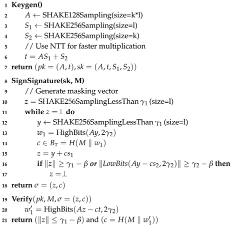
2.2. Dilithium
Dilithium [8] is a Digital Signature Algorithm (DSA) that is lattice-based, relying on the hardness of finding short vectors in lattices for security. The key generation algorithm first generates a matrix A, where each element is 256-dimensional polynomial in the Ring . This is achieved by sampling uniform random values from the SHAKE128 hash value. The algorithm then samples random secret vectors . Using these values, the public key is computed as .
The signing algorithm first generates a masking vector of polynomials y with coefficients less than . After generating y, is computed and is set to high-order bits of the coefficients in this vector. The challenge c is computed as the hash of the message and using SHAKE256. The signature is then computed as . To avoid the leakage of the secret key, we ensure that z does not reveal any dependency on the secret key.
The verification algorithm first computes as the high-order bits of . We then check the conditions to validate the signature. Polynomial multiplication is efficiently performed by applying the Number Theory Transform (NTT) to each element. The Dilithium scheme uses a 23-bit q value of
| Algorithm 1:Main algorithm of Dilithium. |
 |
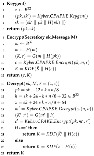
2.3. Kyber
Kyber [7] is an IND-CCA2 secure Key Exchange Algorithm (KEA) that is also lattice-based. Kyber is constructed in two stages, with the IND-CCA2-secure Kyber.CPAPKE. The CPAPKE algorithm is as follows.
- Kyber.CPAPKE.KeyGen. Key generation first generates a matrix A by sampling from the SHAKE128 hash function. It then samples secret s and e using SHAKE128. The public key is computed as , and the secret key is s.
- Kyber.CPAPKE.Encryption. Encryption first generates the matrix matrix by sampling from the SHAKE128 hash function. Then it computes and . The ciphertext c is computed as [0] .
- Kyber.CPAPKE.Decryption. Decryption uses the secret key and ciphertext c to restores u and v by decompressing the ciphertext. The original message is computed as .
Taking all the abovementioned into account, the Kyber.CPAPKE algorithm is detailed in Algorithm 2.
| Algorithm 2:Main algorithm of Kyber. |
 |
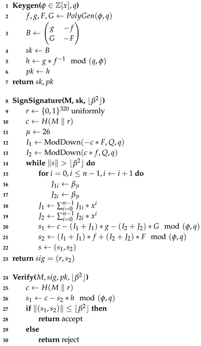
2.4. Falcon
Falcon [12] is a Digital Signature Algorithm (DSA) that utilizes the Gentry-Peikert-Vaikuntanathan (GPV) framework to construct a hash-and-sign lattice-based scheme. Thanks to the use of NTRU lattices, Falcon signatures are substantially shorter than those in any other lattice-based signature scheme with the same security level, while maintaining the same public key size. Originally, Falcon employs Fast Fourier Sampling with double precision floating point operations for fast implementation. However, the modification by [13] allows the use of NTT and modular arithmetic instead of costly double precision floating point operations. Considering all the aforementioned points, the modified Falcon algorithm by [13] is detailed in Algorithm 3.
| Algorithm 3:Main algorithm of Falcon. |
 |
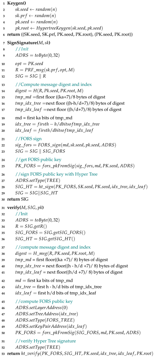
2.5. SPHINCS+
SPHINCS+ [10] is a stateless hash-based scheme, an advancement of the SPHINCS [14] signature scheme with several improvements, including reduced signature size. The signing information is essentially a hypertree signature, a hierarchical structure that combines multiple layers of hash-based XMSS signatures. XMSS (eXtended Merkle Signature Scheme) is a hash-based digital signature scheme that uses a Merkle-tree to generate and verify signatures. In SPHINCS+, an XMSS signature is a Merkle-tree signature consisting of WOTS+ (Winternitz One-Time Signature) used as one-time signatures on the given message and the authentication path in the binary hash-tree. By combining several layers of XMSS trees, a hypertree is formed, which is a variant of . The overall algorithm is detailed on Algorithm 4.
| Algorithm 4:Main algorithm of SPHINCS+. |
 |
3. Related Works and Motivation
Several works, such as [6] and [15], have presented accelerator for two schemes: Dilithium-Kyber, Dilithium-Saber, respectively. The authors in [6] used Kyber’s small Q value size to compute two coefficients simultaneously using Dilithium’s 24-bit datapath, scheduling operations to further utilize each component. As a result, they achieved performance per area comparable to, or in some cases better than, single-scheme accelerators. The authors in [15] optimized Saber [16] to use NTT-based polynomial multiplication and designed a unified NTT multiplier. Both work exploited the fact that theses schemes are lattice-based and shares many common operations. While they support both KEA and DSA schemes, they do not support all four schemes in the selected set. It is worth noting that Saber was not selected as a finalist in the PQC standardization process and is not covered in our work.
The authors in [17] introduced a coprocessor and instruction set for the RISC-V architecture to accelerate various schemes. The key achievement reported is that this design reduces the number of clock cycles required for NTT operations by about 50% compared to the same operations on a standard RISC-V 64-bit integer multiplication (RV64IM) architecture. The authors in [18] presented NTT accelerator specifically targeted for Dilithum and Kyber scheme to accelerate butterfly operations and polynomial multiplication which improved NTT execution time by 3.4×–9.6× in Dilithium and 1.36×–34.16× for Kyber. Both work accelerated part of each schemes in form of coprocessor, which does not implement full scheme. There are also various single-scheme accelerators designed for FPGA or ASIC, such as those in [19,20,21,22,23,24].
Despite these advancements, none of the existing works support all four PQC finalist schemes: Kyber, Dilithium, FALCON, and SPHINCS+. Supporting all four schemes is crucial for:
- 1. Versatility across applications and environments. Allows for a single solution adaptable to different security and performance requirements.
- 2. Reduced need for multiple specialized accelerators. Unifies HW resources, reducing overall cost and complexity.
- 3. Simplified maintenance and updates. Changes can be uniformly applied across all supported schemes and easier to adapt to evolving cryptographic standards.
- 4. Enhanced flexibility and longevity of the HW design. Ensures compatibility with future PQC standards and extends the useful life of the HW investment.
According to the National Institute of Standards and Technology (NIST), having a versatile and comprehensive approach to PQC is essential for addressing the wide-ranging threats posed by quantum computing. By standardizing a set of diverse and robust schemes, NIST aims to provide a secure foundation that can protect sensitive information well into the future. Therefore, our motivation lies in developing a HW design that efficiently supports all four PQC finalist schemes, enduring robust security and broad applicability.
4. Design Methodology
Our paper aims to provide a methodology to implement designs supporting all four PQC finalist schemes-Kyber, Dilithium, FALCON, and SPHINCS+-while accommodating various HW area constraints. Supporting diverse HW area constrains is significant because it allows for the deployment of PQC solutions across a wide range of devices and applications, from resource-constrained IoT devices to high-performance computing systems. This flexibility ensures that robust post-quantum security can be integrated into existing and future technology infrastructures without being limited by HW capabilities.
To achieve this, our approach avoids getting into intricated, detailed optimizations. Instead, we introduce a design space exploration (DSE) method that can be scaled according to any given area constraints. We begin by profiling the performance of each scheme to identify hotspots. Hotspots refer to parts of the scheme where the most computational resources are used. Next, we identify functions that are commonly shared across different schemes, with the goal of implementing them as single, unified HW modules. Following this, we analyze the trade-offs of specific design aspects, such as SRAM size and the number of parallel butterfly units, to optimize overall HW efficiency.
4.1. Performance Profiling
Figure 3 shows the breakdown of executed operations for each schemes. The profiling was performed using the NIST reference implementations on Intel Xeon W5-2465X CPU with 512GB of memory. Each reference implementation was compiled with gcc-11.4.0. using the -O3 optimization parameter. We used Intel VTune Profiler [25] to analyze the profiling result. The breakdown of operations highlights several hotspots:
Keccak. Predominantly in SPHINCS+ (99%) and significantly in Dilithium (43%).
NTT. Major component in Falcon as FFT operations (60.4%).
Polynomial Operations. Present in Falcon as floating point operations, indicating heavy computational load (30.8%).
Reduction. Notable in Kyber (25%) and Dilithium (21%) due to the use of Montgomery reduction.
From the results, we identified three major points that are highly relevant to the crux of our paper:
- P1-Polynomial operations are commonly used, but data-types are different. Three schemes-Dilithium, Kyber, and Falcon—commonly perform operations over polynomial data. Dilithium and Kyber operate over polynomials with coefficients in integer rings, requiring the variants of Montgomery reduction [26] and the Number Theoretic Transform (NTT). Both functions are frequently used and represent significant hotspots in their execution profiles. Falcon also operates over polynomial data but uses polynomials with floating-point coefficients and performs Fast Fourier Transforms (FFT) instead of NTT, eliminating the need for modular reductions.
Whereas the three schemes share a common trait in operating over polynomials, the difference in data types leads to distinct design for HW modules, reducing efficiency. To address this and minimize the need for multiple types of modules, we use a modified variant of Falcon called Peregrine [13], which offers the same functionality but operates over integer rings. Although the modulo bases differ, this approach allows us to reuse modules required for Montgomery reductions and NTT.
- P2-Dissimilar proportion of Keccak. Keccak is another hotspot function present in all four schemes, but accounts for a varying proportions of execution time. It constitutes 43% of Dilithium’s operations, 19% for Kyber, 3.7% for Falcon, and 99% for SPHINCS+. Since there is no clear preference for any specific scheme, (there are no statistical numbers available on which scheme is more frequently used, as PQC schemes are merely developed, not deployed in industries), we assume all four schemes will be used equally.
Figure 2.
Executed number of operations breakdown on each schemes, note that NTT part of Falcon is FFT since the measurement is done to NIST submission package for fair comparison.
Figure 2.
Executed number of operations breakdown on each schemes, note that NTT part of Falcon is FFT since the measurement is done to NIST submission package for fair comparison.
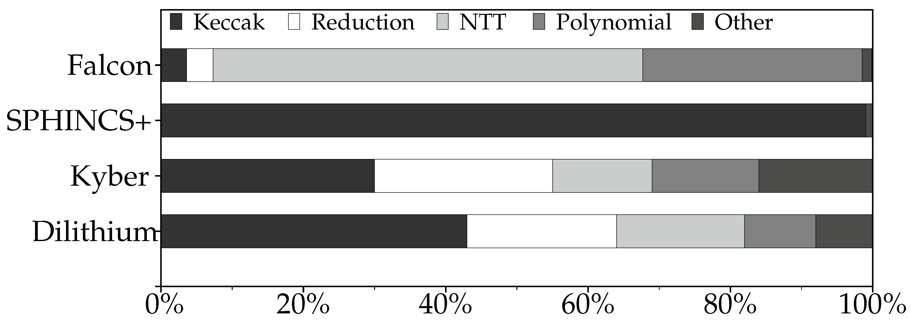
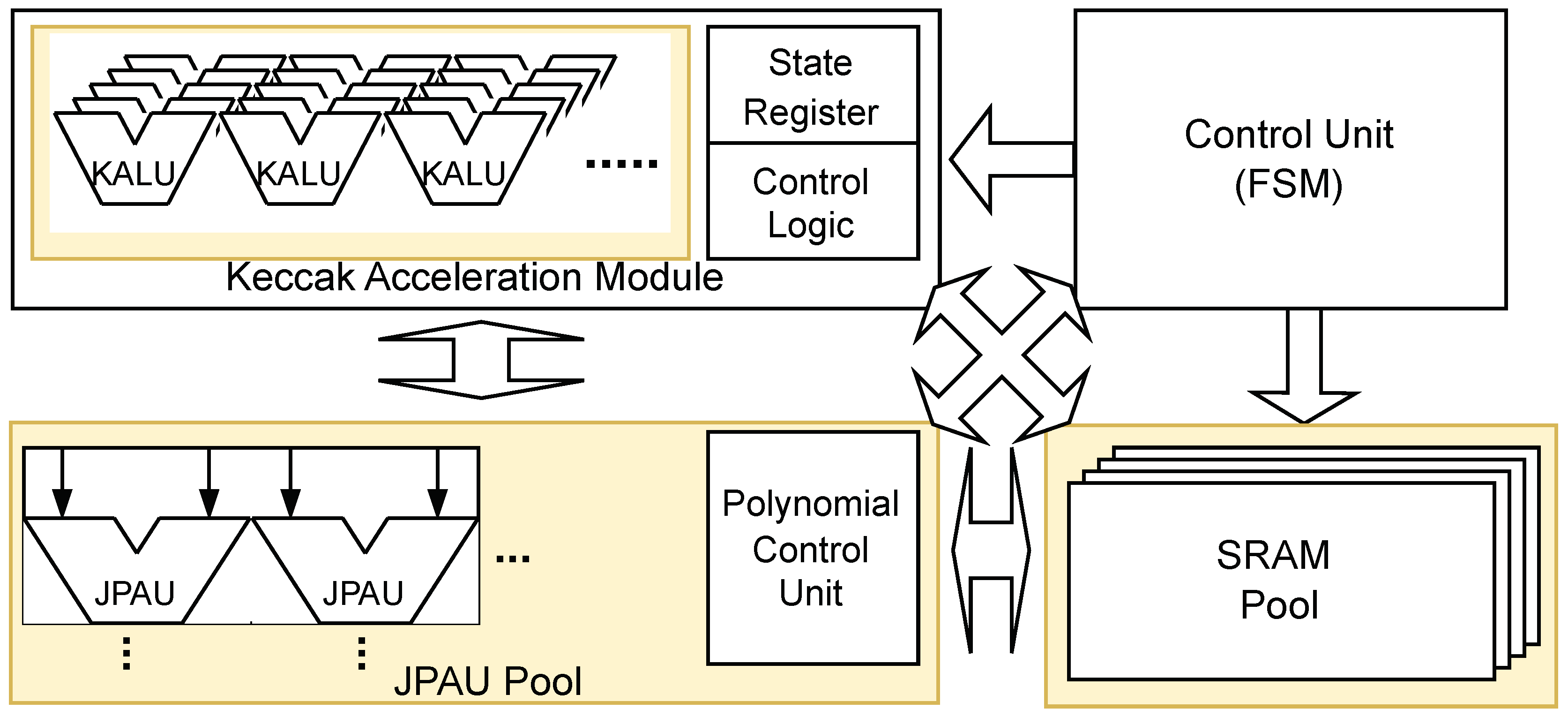
Figure 3.
High-level design of our proposed accelerator with scalable parts are in yellow.
Generally, functions with a high average proportion of usage across schemes should receive more HW resources. However, in practice. users are unlikely to run all schemes concurrently. For example, if someone requires running a DSA, they would use one of the three options, not all three. The average proportion of Keccak is less than 50%. For a user who runs SPHINCS+ only, more than a half of the HW would be idle during computation, as Keccak is primary function used. Conversely, for users running Falcon, dedicating about half of the HW area to Keccak is inefficient since it is rarely used. Based on these circumstances, we settle down to an approach that is not soley optimized for Keccak’s performance but is simplifiable and scalable to arbitrary area constraints Additionally, we incorporate specific optimizations targeting Keccak to balance overall efficiency.
- P3-Distinct high-level operation sequence. Although the schemes share common functions, their high-level operation sequences differ significantly. This is due to not only the inherent difference in algorithm but also the varying polynomial length used in different parameters. For instance, using parallel butterfly modules to compute NTT [27] requires different numbers of stages, and for each stage, we need different numbers of cycles depending on the number of butterfly modules we instantiate.
As a result, we need to integrate multiple control flows for each of the possibilities in order to provide full functionality of the schemes, which will not only lead to large Finite-State-Machine (FSM) as control unit, but also result in different sizes depending on the number of each type of modules we instantiate. Based on these observations, we acknowledge that designing efficient FSM is also a key to enhance the efficiency of our targeted HW.
4.2. Proposed Design
Figure 3 shows our overall design. To support all four schemes with maximum area efficiency, we utilize the results from Section 4.1 to build each component of our accelerator. Our design integrates several key components: Keccak Acceleration Module (KAM), Joint Polynomial Arithmetic Unit (JPAU), and a sophisticated Control Unit. Scalability is achieved by designing components that can adjust their resource usage based on available hardware area, while flexibility is ensured through modular design that allows easy reconfiguration for different schems. Each of these components is detailed in the following subsections.
4.2.1. Keccak Accleration Moudle (KAM)
The first component is the Keccak Acceleration Module (KAM). All four schemes use Keccak operations to compute SHAKE hash values. For scalability, we present three KAM design choices.
- 1. KAM-Small. Optimized for minimal area consumption, it uses 5 KALUs (Keccak ALUs) to compute each step of the Keccak permutation, taking 5 cycles per step.
- 2. KAM-Large. A mid-range solution balancing area and performance, it has 25 KALUs, allowing each Keccak permutation step to be computed in a single cycle.
- 3. KAM-FP. For maximum performance, this variant has a fully-pipelined datapath that computes each round of permutation in a single cycle.
Figure 4 represents the structure of KAM-Small and KAM-Large variant of KAM. Since Keccak permutation needs XOR and bitwise operations over 1600 bit, implementing the entire datapath on KAM could consume significant area and resources. To reduce area, both KAM-Small and KAM-Large use Keccak ALU (KALU) clusters. Each KALU consists of a barrel shifter, XOR, and AND gates to perform bitwise operations. The KAM-Small variant, optimized for minimal area consumption, has 5 KALUs, consuming 5 cycles for each step of Keccak permutation by computing 5 entries per cycle. The KAM-Large variant, which offers a balance between area and performance, has 25 KALUs, consuming 1 cycle per step of Keccak permutation. The KAM-FP variant, instead of having a KALU for sequential computation, has a fully-pipelined datapath for maximum performance. computing each round of permutation in each cycles. A fully-pipelined design means that different stages of the permutation process are handled simultaneously by different pipeline stages, allowing for continuous data processing and maximizing throughput. Figure 5 shows the structure of KAM-FP variant, which can be used when any surplus area is identified.
Each KAM can perform three operations: absorb, squeeze, and permutation. The absorb operation handles the Keccak’s absorb stage, splitting input and adding SHAKE padding to each input block. After adding padding to each input block, we perform XOR to Keccak state stored on Keccak State Register File, and then the permutation operation is performed. This is repeated on each input block. The squeeze operation outputs results after permutation. The output buffer is placed at the output, which allows us to minimize latency during the execution of sampling operations.
The permutation operation performs the Keccak-f1600 permutation, which is a critical part of the SHA-3 and SHAKE algorithms standardized by NIST. The Keccak-f1600 permutation involves 24 rounds of complex transformations, each requiring XOR computations over 1600 bits. Since the Keccak permutation operation is complex, requiring XOR computations over 1600 bits at each stage, the KAM-Small and KAM-Large variants compute the permutation sequentiall, with latencies of 30 and 6 cycles per round, respectively. The fully-pipelined variant, which consumes more area, can compute a round in each cycle providing maximum performance.
Figure 6.
Diagram of JPAU unit
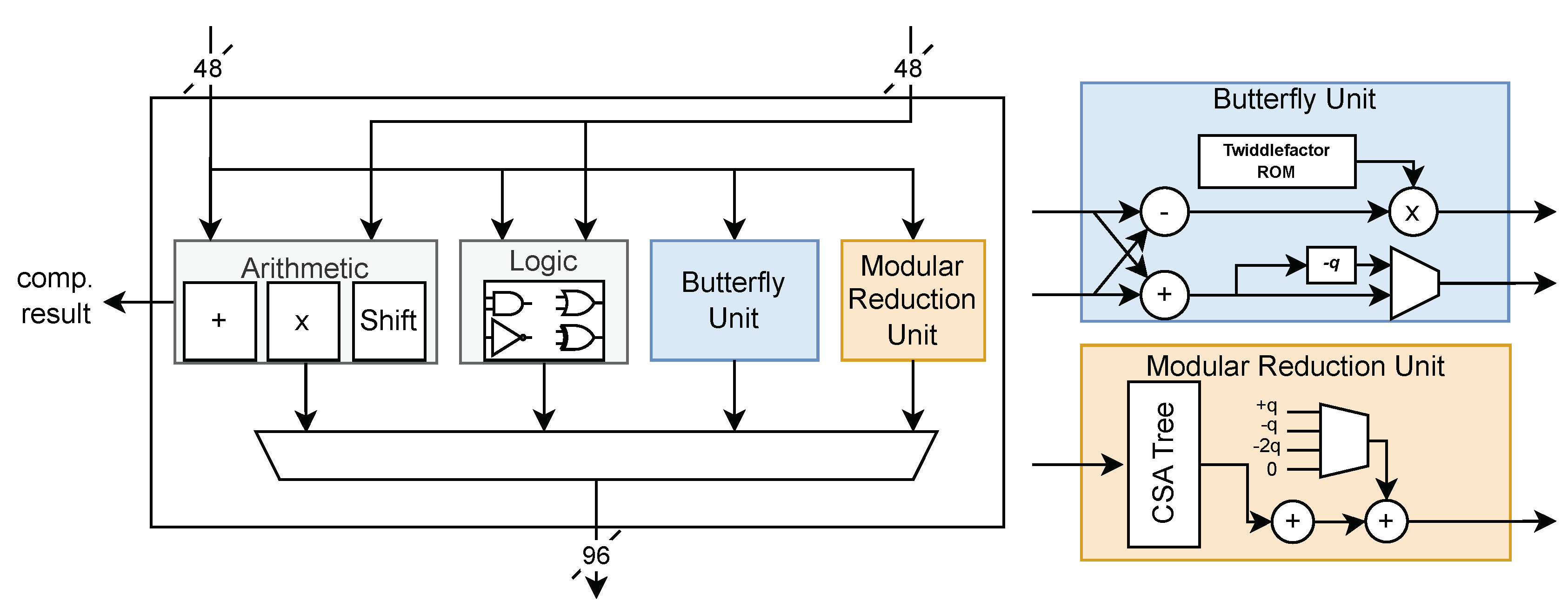
4.2.2. Joint Polynomial Arithmetic Unit (JPAU).
The second component is Joint Polynomial Arithmetic Unit (JPAU). The JPAU serves as a generic ALU to support operations on multiple schemes by breaking down each computation into basic operations such as addition, multiplicaton, and logical operations. Table ?? shows the list of JPAU’s opcodes used for each operation. Since reduction and NTT/INTT operations account for significant portions of execution time (up to 18%, 30.8%, respectively), the butterfly unit and Montgomery reduction unit are also attached to JPAU. These design choices were made to handle the most computationally intensive tasks more efficiently. The included adder can also be used to compute CADDQ function which is used on Dilithium and Kyber. The CADDQ function stands for conditional addition with quotient, which helps manage polynomial coefficients during computations, ensuring they stay within a specific range to maintain algorithm correctness and efficiency.
When performing modular multiplication, reduction should follow the multiplicaton. In this case, the upper 48 bits of the output port are used, with these values stored in a temporary register outside and fed back to the JPAU for reduction. This design ensures accurate and efficient reduction operations, preventing overflow and maintaining consistency. Comparison operations can be performed by subtracting two data values, useful for condition checks such as rejection sampling or signature validation. The comparison result is outputted through a separated port.
Because each scheme uses different q values and coefficients for NTT, a Twiddle factor ROM is also attached to JPAU. This allows for flexible and accurate handling of various polynomial transformations needed for different algorithms. Since Kyber uses 12-bit q value and Dilithium uses the largest q value of 23 bits, we follow the approach of [6], which extends the ALU’s datapath to 24 bits and computes four coefficients instead of two when using the Kyber scheme. This significantly increases throughput and utilization for Kyber, optimizing the hardware for its specific requirements.
Each JPAU can perform coefficient-wise operations on two coefficients simultaneously, with each port receiving two coefficients from two different polynomials. Adding more JPAUs can further accelerate polynomial operations, enhancing overall computational efficiency. The JPAU is fully-pipelined, maximizing throughput and minimizing latency. by ensuring that multiple stages of computation can be processed concurrently without waiting for previous stages to complete. This pipelining is crucial for maintaining high performance across the supported cryptographic schemes.
4.2.3. Control Unit
The control unit is responsible for sending commands to JPAU and Keccak modules, as well as managing memory and mux addresses. It is implemented as a large FSM with states for each scheme. Building a separate FSM for each scheme can result in a significant area overhead due to the need to construct separate states for each of the four schemes. This can lead to a large state register and also delays in control signal paths.
To overcome this problem, we designed a Unified Polynomial Control Unit (UPCU) separate from main control unit. Figure 7 shows the diagram for main control unit and UPCU. The main control unit handles the high-level control flow for each scheme, including initializing operations and managing the overall sequence of tasks. For instance, in the Dilithium_sign operation, the control unit starts by initializing and performing the SHAKE256 operation, then moves to Keccak operations and matrix expansion. Similarly, for Falcon_sign, it handles random sampling and then proceeds to polynomial multiplication.
When a JPAU operation is needed, instead of main control unit sending all JPAU opcodes and MUX control signals, it sends a predefined polynomial function code to the UPCU. The UPCU then takes the function code along with information such as the scheme and security level and starts sending the appropriate JPAU opcodes and SRAM memory addresses. The UPCU adjusts parameters such as N for each scheme and security level, eliminating the need to create separate control sequence for each scheme. This segregation of detailed polynomial control to the UPC minimizes the FSM complexity in the main control unit. This design ensures that the control logic is streamlined and efficient, capable of handling various polynomial operations without excessive state overhead. The detailed operation of the UPCU can be summarized as follows:
- Sample_polynomial. The UPCU initiates and manages the polynomial sampling process. This includes setting up necessary registers and handling data flow for efficient sampling.
- Polynomial_multiplication. The UPCU controls the sequence of multiplication and accumulation operations, coordinating data flow and setting up operands for the computation.
- NTT_INTT. The UPCU manages the NTT and INTT operations, controlling the butterfly units and Montgomery reduction units. It ensures efficient operations by adjusting control signals and managing data flow through various stages, utilizing the Twiddle factor ROM for different schemes.
By implementing these processes within the UPCU separately, the complexity of the overall FSM is significantly reduced, leading to higher area efficiency. This approach allows the control unit to handle the operations of all four PQC schemes without incurring a large area overhead, this enhancing the overall performance and efficiency of the hardware design.
5. Implementation
We synthesized our design using Design Compiler N-2017.09-SP2 [29] with 15nm Opencell library [30]. We use kGE as a metric to ensure a fair comparison across different silicon processes, as it normalizes the differences in technology nodes. This standardization allows us to compare designs more effectively regardless of the specific fabrication technology used.
Our target kGE (kilo Gate Equivalent) is set to 600 kGE, which represents the sum of kGE values from various reported works, as there is no single reference implementation supporting all four PQC finalist schemes. This target was determined by combining the most efficient individual implementations for each scheme to achieve the minimum possible kGE sum. Specifically, we considered Gupta et al. [20]’s 157 kGE for Dilithium, Bisheh-Nisar et al. [24]’s 93 kGE for Kyber, Lee et al.[19]’s 98.729 kGE for Falcon verification and Soni et al.[28]’s 181.120 kGE for Falcon-1024 signing, and Wagner et al.[21]’s 84 kGE for SPHINCS+. Adding these values results in a total of 613.849 kGE. However, we conservatively set our target to 600 kGE to provide a more challenging and aggressive goal, ensuring a more efficient and streamlined design. It is worth noting that no implementation for Falcon’s key generation was available, so this function’s kGE is not included in our target kGE. Additionally, while Aikata et al.[6] implemented both Dilithium and Kyber, their reported 747 kGE was deemed too high. Thus, we opted for the combination of separate implementations by Gupta et al.[20] for Dilithium and Bisheh-Nisar et al.[24] for Kyber, as this resulted in a lower total kGE target. This approach allows us to set a realistic and competitive target for our unified implementation of all four PQC finalist schemes.
We first build a small baseline design, Ours_Baseline with 4×JPAU and KAM-Small variant, and extend our design with changing KAM-Small to KAM-Large to build Ours_S variant. Our first priority in scaling up is the JPAU cluster, which generally affects each scheme’s performance. After scaling up the JPAU by 4× to 8×, we build Ours_M variant, we then check whether we have margin left. If we have spare resources, we can allocate more to use faster KAM modules. By changing to the KAM-FP, we build the Ours_L variant, which results in 611.389 kGE, which satisfies our target kGE. Table 3 shows synthesis result of our proposed design compared with other designs.
6. Evaluation
We compare the performance of our design variants presented in Section 5, namely Ours_S, Ours_M and Ours_L with prior works. Parameters used for evaluation of each PQC scheme is listed on Table 5 and Table 9. In cases where no prior HW implementation exists for certain operations (e.g., key generation for Falcon and SPHINCS+), we use the performance of CPU implementations with AVX extensions as a baseline for comparison. These CPU cycle counts, reported in the NIST reference submissions, are converted to throughput numbers to provide a point of reference. For ease of comparison and representations, we present the performance results for Dilithium and Kyber in a single subsection, as they were both implemented in the work by Aikata et al.[6]. The results for Falcon and SPHINCS+ are discussed in separate subsections due to their unique implementation characteristics and the lack of comprehensive HW implementations for all operations. This approach allows us to provide a comprehensive comparison across all schemes and operations, even in cases where direct hardware implementation comparisons are not available. It also enables us to highlight the advantages of our unified design across different PQC algorithms.
6.1. Dilithium and Kyber
In Dilithium and Kyber, we compared our design with current state-of-the-art ASIC accelerators that support more than two different parameters, namely Aikata et al. [15], Aikata et al. [6] and state-of-art Dilithium ASIC accelerator, Gupta et al. [20]. Table 4 shows the normalized throughput of our variants on Dilithium and Kyber compared to other accelerators. The throughput is calculated in the same manner as benchmarks in the NIST submission package, which performs Keygen, Sign/Encapsulate, Verify/Decapsulate on each security parameter.

Table 4.
Relative throughput on Dilithium and Kyber.
| Parameter | Gupta et al. [20] |
Aikata et al. [15] |
Akata et al. [6] |
Ours_S | Ours_M | Ours_L | |
| Keygen | Dilithium2 | - | 0.52 | 1.27 | 1.00 | 1.74 | 2.09 |
| Dilithium3 | 0.57 | 1.39 | 1.00 | 1.76 | 2.08 | ||
| Dilithium5 | 1.11 | 0.61 | 1.50 | 1.00 | 1.77 | 2.08 | |
| Kyber512 | - | - | 4.66 | 1.00 | 1.04 | 2.18 | |
| Kyber768 | - | - | 3.47 | 1.00 | 1.04 | 2.26 | |
| Kyber1024 | - | - | 3.08 | 1.00 | 1.04 | 2.31 | |
| Sign/Encapsulate | Dilithium2 | - | 0.96 | 2.31 | 1.00 | 1.90 | 2.01 |
| Dilithium3 | - | 1.08 | 2.63 | 1.00 | 1.92 | 2.01 | |
| Dilithium5 | 2.39 | 1.35 | 3.30 | 1.00 | 1.93 | 2.01 | |
| Kyber512 | - | - | 2.85 | 1.00 | 1.07 | 2.74 | |
| Kyber768 | - | - | 2.57 | 1.00 | 1.07 | 2.71 | |
| Kyber1024 | - | - | 2.34 | 1.00 | 1.07 | 2.68 | |
| Verify/Decapsulate | Dilithium2 | - | 0.83 | 2.02 | 1.00 | 1.83 | 2.00 |
| Dilithium3 | - | 0.85 | 2.08 | 1.00 | 1.85 | 2.01 | |
| Dilithium5 | 1.71 | 0.86 | 2.11 | 1.00 | 1.86 | 2.03 | |
| Kyber512 | - | - | 2.26 | 1.00 | 1.11 | 2.65 | |
| Kyber768 | - | - | 1.96 | 1.00 | 1.11 | 2.61 | |
| Kyber1024 | - | - | 2.10 | 1.00 | 1.11 | 2.57 |
Table 5.
Used parameter on Dilithium and Kyber.
| Dilithium2 | Dilithium3 | Dilithium5 | |
| q | 8380417 | 8380417 | 8380417 |
| N | 256 | 256 | 256 |
| (k,l) | (4,4) | (6,5) | (8,7) |
| (q-1)/88 | (q-1)/32 | (q-1)/32 | |
| Kyber512 | Kyber768 | Kyber1024 | |
| q | 3329 | 3329 | 3329 |
| N | 256 | 256 | 256 |
| k | 2 | 3 | 4 |
| 3 | 2 | 2 | |
| 2 | 2 | 2 | |
| (10,4) | (10,4) | (10,5) | |
For Dilithium, due to significant loads on matrix generation, changing the Keccak module to the KAM-FP variant can improve performance by up to 8%. Compared with Aikata et al. [15], who accelerated both Dilithium and Saber schemes, our Ours_M and Ours_L variants achieved a 3.11× and 3.69× speedup on Keygen, a 1.73× and 1.81× speedup on Sign, and a 2.18× and 2.38× speedup on Verify, on average, with 2.65× and 2.77× larger kGE counts, respectively. Ours_S variant also achieved speedup of 1.76×, 1.17× average on Keygen and Verify, while having 0.87×, lower throughput on Sign with having 1.43× larger kGE counts.
Comparing to Aikata et al. [6], the current state-of-the-art implementation for accelerating both Dilithium and Kyber schemes, our Ours_M and Ours_L variants achieved an average throughput increase of 1.51× and 1.27× in Keygen, respectively. In Sign, our variants had a slightly lower throughput of 0.75× and 0.71×, and in Verify, the throughput was 0.89× and 0.97× lower, on average, compared to Aikata et al. [6]. However, Ours_M and Ours_L variants have significantly lower kGE counts, which are 0.27× and 22× lower than those of Aikata et al. [6]. Ours_S variant had lower throughput of 0.72×, 0.37× 0.48× average on Keygen, Sign and Verify, respectively. While having 2.63× smaller kGE counts.
For Kyber, each JPAU in our design can perform operations on four coefficients simultaneously, significantly reducing the time spent using the JPAU and increasing the proportion of time dedicated to the KAM. Replacing the KAM from KAM-Large to KAM-FP when transitioning from Ours_M to Ours_L variant significantly increased the throughput in Kyber. Ours_S and {Ours_M, Ours_L} variant showed an average of 0.72×, 0.29×, 0.62× lower throughput in Keygen. In Encapsulate, the Ours_S and {Ours_M, Ours_L} variant shows differences of 0.38×,0.42×,1.05×, and on Decapsulate, 0.47×,0.53×, 1.24×, respectively, compared to Aikata et al. [6]. This is because our design focuses on breaking down each function to maximize shared functions, whereas Aikata et al. [6] focuses on accelerating Kyber by consuming as many hardware resources as possible.
6.2. Falcon
Table 6 shows our speedup factor on Falcon [13] compared with other Falcon accelerators implemented on ASIC. Since it is difficult to find works that have implemented the full scheme in ASIC, we compared each functionality (namely Keygen, Sign, Verify) with existing accelerators including SW implementation on CPU with AVX extensions reported in [9]. Our accelerator achieved speedup of 8.06×, 14.76× and 14.76× on Keygen, 4.03×, 6.49×, 6.49× on Sign, 7.87×, 15.66×, 15.76× on Verification compared to CPU with AVX extensions Ours_S and {Ours_M, Ours_L} variants respectively. Since the Keccak operation accounts for about 0.1% of total Falcon operations, using KAM-FP almost does not affect overall performance. Our accelerator outperformed prior works implemented in ASIC in all three variants with more than 100× speedups.
6.3. SPHINCS+
In SPHINCS+, since the current state-of-art design is on FPGA, we compare our designs with both FPGA-based work and existing ASIC implementations in Table 8. We also included a comparison with CPU performance with AVX extensions as reported in [10] as the baseline for Keygen, since no prior work has targeted the Keygen of SPHINCS+. SPHINCS+’s performance is highly dependent on the throughput of KAM. Due to heavy use of SHAKE256 hash functions for tree hashing, utilizing KAM-Large and KAM-FP dramatically increases overall throughput.
Since there are many parameters in SPHINCS+, we selected the most time-consuming parameters of 256s-simple and 256s-robust, which are also implemented in [21]. The parameters are represented in Table 9. Note that the robust parameter adds an extra layer of SHAKE to generate bitmasks and XOR the bitmask to the input when hashing each inputs. Ours_S and Ours_M variant outperformed CPUs with a speedup of 33.3× in signing signatures. Ours_L variant, which has KAM-FP, can further accelerate up to 99×. Compared with the current state-of-art FPGA implementation in [31], our design has 1.2× and 3.6× higher throughput on {Ours_S, Ours_M} and Ours_L variant, respectively.
Table 9.
Used parameter on SPHINCS+
| Parameter | n | h | d | log(t) | k | w | NIST Security Level |
| SPHINCS+-256s | 32 | 64 | 8 | 14 | 22 | 16 | 5 |
| SPHINCS+-256s robust | 32 | 64 | 8 | 14 | 22 | 16 | 5 |
7. Conclusions
The advent of quantum computing poses a significant threat to classical cryptosystems, creating a need for Post-Quantum Cryptography (PQC). In response, NIST announced four schemes for standardization, each with its own advantages and disadvantages, such as Falcon’s short signature length. Prior works have primarily focused on accelerating individual schemes, making integration with other schemes challenging. We presented a scalable accelerator designed to support all four NIST-selected algorithms, incorporating a modified version of FALCON. Through function-level profiling, we identified common operations shared between schemes and designed each component of our accelerator accordingly. Our design achieves nearly the same throughput compared with state-of-the-art multi-scheme accelerator with small area overhead on Dilithium and Kyber and also achieved significant speedup compared other single-scheme accelerators on Falcon and SPHINCS+. Overall, our design provides a general speedup across all four NIST-selected schemes, demonstrating its effectiveness and versatility in addressing the challenges posed by quantum computing to cryptographic systems.
Author Contributions
Conceptualization, methodology H.O.; Software,Investigation,Data curation, Writing-original draft, H.J.; All authors have read and agreed to the published version of the manuscript.
Funding
This work was supported by the National Research Foundation of Korea(NRF) grant funded by the Korea government(MSIT) (No. RS-2022-00166529) , National Research Foundation of Korea(NRF) grant funded by the Korea government(MSIT) (RS-2023-00277326) , Institute of Information & communications Technology Planning & Evaluation (IITP) under the artificial intelligence semiconductor support program to nurture the best talents (IITP-2023-RS-2023-00256081) grant funded by the Korea government(MSIT) , Institute of Information & communicationsTechnology Planning & Evaluation (IITP) grant funded by the Koreagovernment(MSIT) (RS-2023-00277060, Development of open edge AI SoC hardware and software platform) , MSIT(Ministry of Science and ICT), Korea, under the ITRC(Information Technology Research Center) support program(IITP-2023-2020-0-01602) supervised by the IITP(Institute for Information & Communications Technology Planning & Evaluation) , Inter-University Semiconductor Research Center (ISRC) , BK21 FOUR program of the Education and Research Program for Future ICT Pioneers, Seoul National University in 2023 The EDA tool was supported by the IC Design Education Center(IDEC), Korea.
Conflicts of Interest
The authors declare no conflict of interest.
| 1 | For simplicity, we will refer to CRYSTALS-Kyber as Kyber and CRYSTALS-Dilithium as Dilithium throughout this paper. |
References
- Carracedo, J.M.; Milliken, M.; Chouhan, P.K.; Scotney, B.; Lin, Z.; Sajjad, A.; Shackleton, M. Cryptography for Security in IoT. In Proceedings of the 2018 Fifth International Conference on Internet of Things: Systems, Management and Security; 2018; pp. 23–30. [Google Scholar] [CrossRef]
- Katzenbeisser, S.; Polian, I.; Regazzoni, F.; Stöttinger, M. Security in Autonomous Systems. In Proceedings of the 2019 IEEE European Test Symposium (ETS); 2019; pp. 1–8. [Google Scholar] [CrossRef]
- Muzikant, P.; Willemson, J. Deploying Post-quantum Algorithms in Existing Applications and Embedded Devices. In Proceedings of the Ubiquitous Security; Wang, G.; Wang, H.; Min, G.; Georgalas, N.; Meng, W., Eds., Singapore; 2024; pp. 147–162. [Google Scholar]
- Kim, D.; Choi, H.; Seo, S.C. Parallel Implementation of SPHINCS+ With GPUs. IEEE Transactions on Circuits and Systems I: Regular Papers 2024, 71, 2810–2823. [Google Scholar] [CrossRef]
- Shor, P.W. Polynomial-time algorithms for prime factorization and discrete logarithms on a quantum computer. SIAM review 1999, 41, 303–332. [Google Scholar] [CrossRef]
- Aikata, A.; Mert, A.C.; Imran, M.; Pagliarini, S.; Roy, S.S. KaLi: A Crystal for Post-Quantum Security Using Kyber and Dilithium. IEEE Transactions on Circuits and Systems I: Regular Papers 2023, 70, 747–758. [Google Scholar] [CrossRef]
- Avanzi, R.; Bos, J.; Ducas, L.; Kiltz, E.; Lepoint, T.; Lyubashevsky, V.; Schanck, J.M.; Schwabe, P.; Seiler, G.; Stehlé, D. CRYSTALS-Kyber, 2020. Algorithm Specifications and Supporting Documentation, Submission to the NIST post-quantum project.
- Ducas, L.; Kiltz, E.; Lepoint, T.; Lyubashevsky, V.; Schwabe, P.; Seiler, G.; Stehlé, D. CRYSTALS-Dilithium, 2020. Algorithm Specifications and Supporting Documentation, Submission to the NIST post-quantum project.
- Fouque, P.A.; Hoffstein, J.; Kirchner, P.; Lyubashevsky, V.; Pornin, T.; Prest, T.; Ricosset, T.; Seiler, G.; Whyte, W.; Zhang, Z. Falcon: Fast-Fourier Lattice-based Compact Signatures over NTRU, 2020. Specification v1.2.
- Aumasson, J.P.; Bernstein, D.J.; Beullens, W.; Dobraunig, C.; Eichlseder, M.; Fluhrer, S.; Gazdag, S.L.; Hülsing, A.; Kampanakis, P.; Kölbl, S.; et al. SPHINCS+ specification, 2022. Submission to the NIST post-quantum project.
- NIST. Selected Algorithms 2022, July 2022. https://csrc.nist.gov/projects/post-quantum-cryptography/selected-algorithms-2022.
- Prest, T.; Fouque, P.A.; Hoffstein, J.; Kirchner, P.; Lyubashevsky, V.; Pornin, T.; Ricosset, T.; Seiler, G.; Whyte, W.; Zhang, Z. Falcon. Post-Quantum Cryptography Project of NIST, 2020. [Google Scholar]
- Seo, E.Y.; Kim, Y.S.; Lee, J.W.; No, J.S. Peregrine: toward fastest FALCON based on GPV framework. Cryptology ePrint Archive 2022. [Google Scholar]
- Bernstein, D.J.; Hopwood, D.; Hülsing, A.; Lange, T.; Niederhagen, R.; Papachristodoulou, L.; Schneider, M.; Schwabe, P.; Wilcox-O’Hearn, Z. SPHINCS: Practical Stateless Hash-Based Signatures. In Proceedings of the Advances in Cryptology – EUROCRYPT 2015; Oswald, E.; Fischlin, M., Eds., Berlin, Heidelberg; 2015; pp. 368–397. [Google Scholar]
- Aikata, A.; Mert, A.C.; Jacquemin, D.; Das, A.; Matthews, D.; Ghosh, S.; Roy, S.S. A Unified Cryptoprocessor for Lattice-Based Signature and Key-Exchange. IEEE Transactions on Computers 2023, 72, 1568–1580. [Google Scholar] [CrossRef]
- Basso, A.; Bermudo Mera, J.M.; D’Anvers, J.P.; Karmakar, A.; Sinha Roy, S.; Van Beirendonck, M.; Vercauteren, F. SABER: Mod-LWR based KEM (Round 3 Submission), 2017. SABER submission package for round 3.
- Lee, J.; Kim, W.; Kim, J.H. A Programmable Crypto-Processor for National Institute of Standards and Technology Post-Quantum Cryptography Standardization Based on the RISC-V Architecture. Sensors 2023, 23. [Google Scholar] [CrossRef] [PubMed]
- Nguyen, T.H.; Kieu-Do-Nguyen, B.; Pham, C.K.; Hoang, T.T. High-Speed NTT Accelerator for CRYSTAL-Kyber and CRYSTAL-Dilithium. IEEE Access 2024, 12, 34918–34930. [Google Scholar] [CrossRef]
- Lee, Y.; Youn, J.; Nam, K.; Jung, H.H.; Cho, M.; Na, J.; Park, J.Y.; Jeon, S.; Kang, B.G.; Oh, H.; et al. An Efficient Hardware/Software Co-Design for FALCON on Low-End Embedded Systems. IEEE Access 2024, 12, 57947–57958. [Google Scholar] [CrossRef]
- Gupta, N.; Jati, A.; Chattopadhyay, A.; Jha, G. Lightweight Hardware Accelerator for Post-Quantum Digital Signature CRYSTALS-Dilithium. IEEE Transactions on Circuits and Systems I: Regular Papers 2023, 70, 3234–3243. [Google Scholar] [CrossRef]
- Wagner, A.; Oberhansl, F.; Schink, M. To Be, or Not to Be Stateful: Post-Quantum Secure Boot using Hash-Based Signatures. In Proceedings of the Proceedings of the 2022 Workshop on Attacks and Solutions in Hardware Security, New York, NY, USA, 2022, ASHES’22,; pp. 85–94. [CrossRef]
- Mandal, S.; Roy, D.B. KiD: A Hardware Design Framework Targeting Unified NTT Multiplication for CRYSTALS-Kyber and CRYSTALS-Dilithium on FPGA. In Proceedings of the 2024 37th International Conference on VLSI Design and 2024 23rd International Conference on Embedded Systems (VLSID); 2024; pp. 455–460. [Google Scholar] [CrossRef]
- Beckwith, L.; Nguyen, D.T.; Gaj, K. Hardware Accelerators for Digital Signature Algorithms Dilithium and FALCON. IEEE Design & Test. [CrossRef]
- Bisheh-Niasar, M.; Azarderakhsh, R.; Mozaffari-Kermani, M. A Monolithic Hardware Implementation of Kyber: Comparing Apples to Apples in PQC Candidates. In Proceedings of the Progress in Cryptology – LATINCRYPT 2021; Longa, P.; Ràfols, C., Eds., Cham; 2021; pp. 108–126. [Google Scholar]
- Inc., I. Inc., I. Intel Vtune Profiler, 2023. https://www.intel.com/content/www/us/en/develop/documentation/vtune-help/top.html/.
- Montgomery, P.L. Modular multiplication without trial division. Mathematics of computation 1985, 44, 519–521. [Google Scholar] [CrossRef]
- Bekele, A. Cooley-tukey fft algorithms. Advanced algorithms 2016. [Google Scholar]
- Soni, D.; Basu, K.; Nabeel, M.; Aaraj, N.; Manzano, M.; Karri, R. Hardware Architectures for Post-Quantum Digital Signature Schemes 2021. [CrossRef]
- SYNOPSYS Inc.. Synopsys Design Cimpiler. https://www.synopsys.com/implementation-and-signoff/rtl-synthesis-test/dc-ultra.html.
- Martins, M.; Matos, J.M.; Ribas, R.P.; Reis, A.; Schlinker, G.; Rech, L.; Michelsen, J. Open Cell Library in 15nm FreePDK Technology. In Proceedings of the Proceedings of the 2015 Symposium on International Symposium on Physical Design, New York, NY, USA, 2015; ISPD ’15, ; pp. 171–178. [CrossRef]
- Amiet, D.; Leuenberger, L.; Curiger, A.; Zbinden, P. FPGA-based SPHINCS+ Implementations: Mind the Glitch. In Proceedings of the 2020 23rd Euromicro Conference on Digital System Design (DSD); 2020; pp. 229–237. [Google Scholar] [CrossRef]
Figure 1.
General process of KEA and DSA.
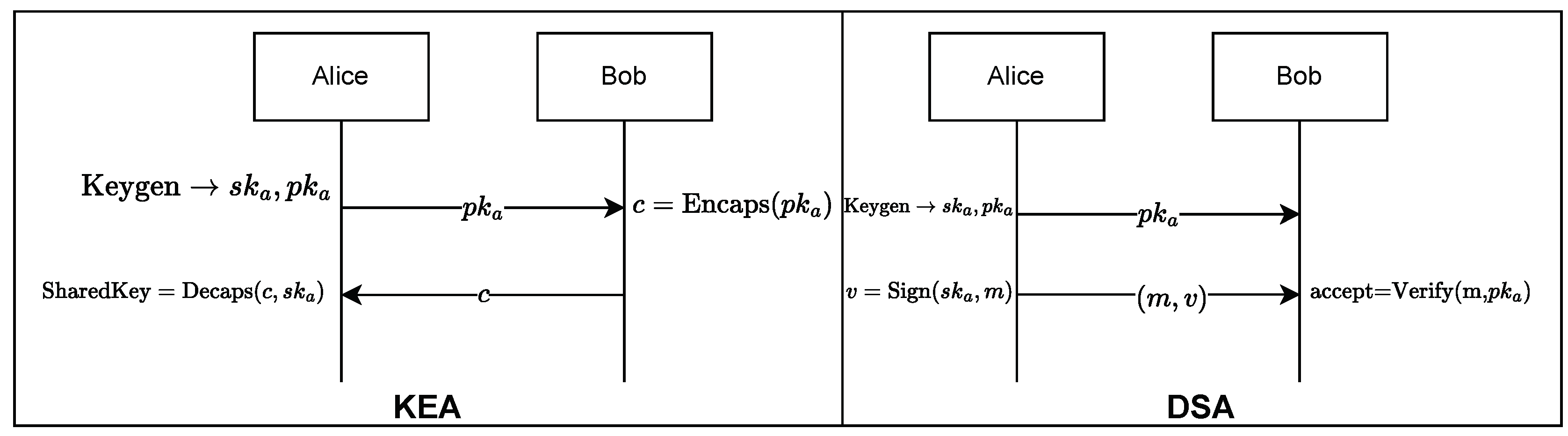
Figure 4.
Diagram of KAM-Small, KAM-Large variant. Note that the number of KALU in Keccak ALU cluster can vary depending on each variant.
Figure 4.
Diagram of KAM-Small, KAM-Large variant. Note that the number of KALU in Keccak ALU cluster can vary depending on each variant.
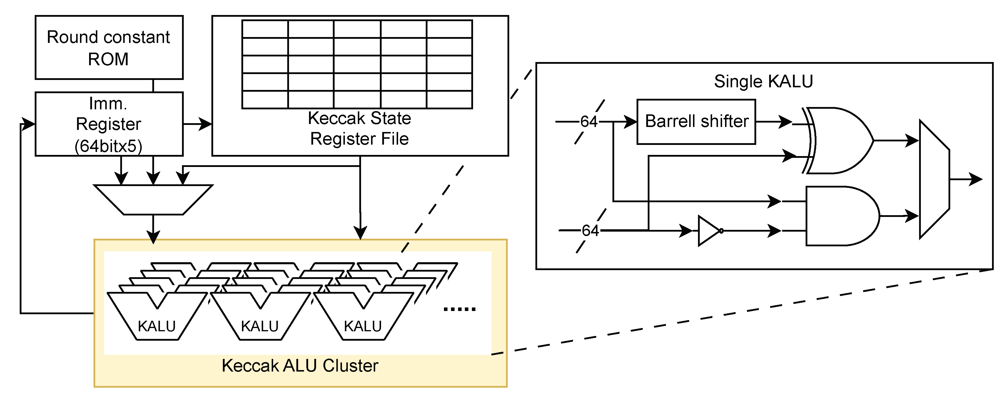
Figure 5.
Diagram of KAM-FP variant perfroming single stage of Keccak Permutation.
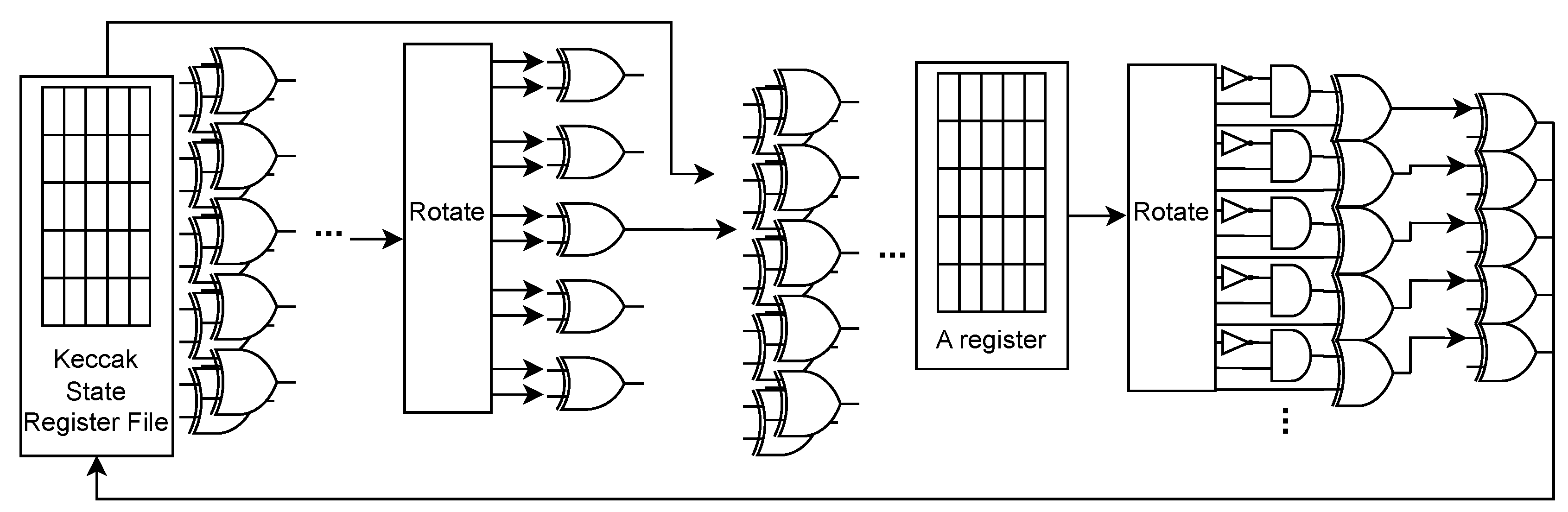
Figure 7.
Diagram of control unit with UPCU.
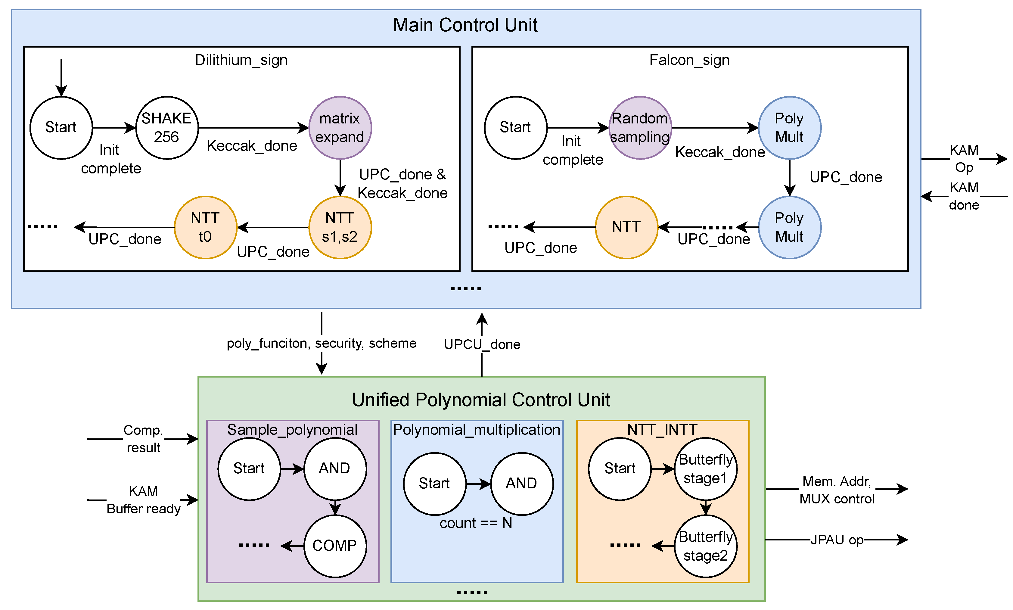
Table 1.
Selected Finalist PQC schemes.
| Kyber | Dilithium | FALCON | SPHINCS+ | |
| Algorithm Type | Key Exchange (KEA) | Digital Signature (DSA) | ||
| Based Approach | Lattice-Based | Hash-Based | ||
Table 2.
List of JPAU’s opcodes.
| Mnenomic | Opcode | Discription |
| NOP | 0000 | No operation, Do nothing |
| ADD | 0001 | Result[i]←vec_a[i]+vec_b[i] |
| SUB | 0010 | Result[i]←vec_a[i]-vec_b[i] |
| CADDQ | 0011 | Result[i]←(vec_a[i] <0) ? vec_a[i] +Q : vec_a[i] |
| MULT | 0100 | Result[i]←vec_a[i] × vec_b[i] |
| SHIFT | 0101 | Result[i]←vec_a[i] <<SHIFT_AMOUNT |
| REDUCE | 0110 | Result[i]←MontgomeryReduction(vec_a[i] ) |
| AND | 0111 | Result[i]←vec_a[i] AND vec_b[i] |
| OR | 1000 | Result[i]←vec_a[i] OR vec_b[i] |
| XOR | 1001 | Result[i]←vec_a[i] XOR vec_b[i] |
| NTT_BUTTERFLY | 1010 | Result←Butterfly(vec_a) |
| INTT_BUTTERFLY | 1011 | Result←InvButterfly(vec_a) |
| COMP | 1100 | Comp_result[i] ← COMPARE(vec_a[i], vec_b[i]) |
| RESERVED | 1101-1111 | - |
Table 3.
Synthesis result compared with other works.
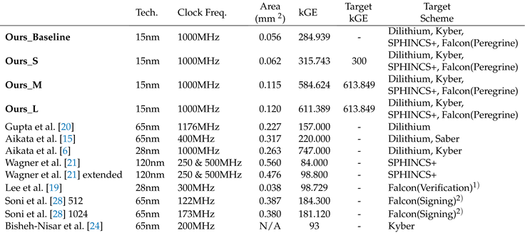 |
1)Implemented verification algorithm in Falcon, 2)Implemented signing algorithm in Falcon
Table 6.
Relative throughput on Falcon
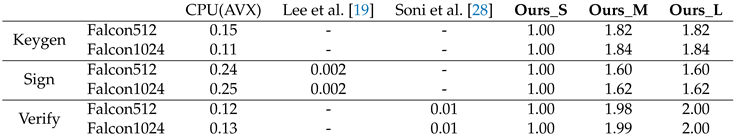 |
Table 7.
Used parameter on Falcon.
| Falcon512 | Falcon1024 | Peregrine *512 | Peregrine*1024 | |
| q | 12289 | 12289 | 12289 | 12289 |
| N | 512 | 1024 | 512 | 1024 |
| b | 34034726 | 70265242 | 34034726 | 150700176 |
*Modified Falcon scheme presented in [13]
Table 8.
Relative throughput on SPHINCS+.
| Parameter | CPU (AVX) |
Wagner et al. [21] |
Wagner et al. [21] extended |
Amiet et al. [31] |
Ours_S | Ours_M | Ours_L | |
| Keygen | 256s-simple | 0.05 | - | - | - | 1.00 | 1.00 | 2.95 |
| 256s-robust | 0.04 | - | - | - | 1.00 | 1.00 | 2.97 | |
| Sign | 256s-simple | 0.03 | - | - | 0.82 | 1.00 | 1.00 | 2.95 |
| 256s-robust | 0.03 | - | - | 0.83 | 1.00 | 1.00 | 2.97 | |
| Verify | 256s-simple | 0.01 | 0.03 | 0.04 | 0.06 | 1.00 | 1.00 | 2.58 |
| 256s-robust | 0.01 | 0.02 | 0.04 | 0.08 | 1.00 | 1.00 | 2.59 |
Disclaimer/Publisher’s Note: The statements, opinions and data contained in all publications are solely those of the individual author(s) and contributor(s) and not of MDPI and/or the editor(s). MDPI and/or the editor(s) disclaim responsibility for any injury to people or property resulting from any ideas, methods, instructions or products referred to in the content. |
© 2024 by the authors. Licensee MDPI, Basel, Switzerland. This article is an open access article distributed under the terms and conditions of the Creative Commons Attribution (CC BY) license (http://creativecommons.org/licenses/by/4.0/).
Copyright: This open access article is published under a Creative Commons CC BY 4.0 license, which permit the free download, distribution, and reuse, provided that the author and preprint are cited in any reuse.


