1. Introduction
Tungsten is a material presenting outstanding properties (higher melting temperature from all metals, good thermal conductivity and stability), being of high interest in many fields, including the domestic, industrial and high technology ones. These include lighting (for light bulbs filaments), electrical engineering (like alloys of W-Cu for electrical contacts), electronics (for electrons emitters, thin films in microelectronic devices, heat sinks), high temperature technique (like heating elements and radiation shields in high temperature furnaces, thermocouples W/W-Re), metal machining (welding electrodes, cutting), X-Ray generation (with applications in medicine and other fields), coating technologies (for evaporation boats or sputtering targets), chemical industry (as catalyst, high temperature components for production of quartz glass, spring materials in corrosive media), melting metallurgy (for alloys and steel production), space aviation (for ignition tubes in rocket engines, guide nozzles), aviation (for aircraft balance weight ), military applications (for high kinetic energy penetrators in ammunition, armor plating) and not at least for leisure time and sports equipment (like parts of professional darts, golf club components, counter balance weights in Formula 1 racing cars). This long list is not exhaustive, more applications of W material are available in [
1].
Also, tungsten and its compounds find modern applications in nanotechnology. Thin films of W find application in spintronics [
2,
3] or for superconducting transition-edge sensors used as ultrasensitive thermometers [
4]. Moreover, nanostructured tungsten oxide surfaces (obtained as thin films [
5,
6] or from nanoparticles [
7]) react with many gas molecules, making them a perfect choice for developing new types of gas sensors [
8]. Also, nano-composites obtained from WO
3 based nanocomposites (with conductive polymers or carbon nanostructures) may present enhanced electrochemical properties [
9], or enhanced capacitive performance [
10,
11].
Tungsten is also considered “the best, if not the only, material to withstand the extraordinary operating conditions in a nuclear fusion reactor divertor” [
1]. In this part of the reactor, a large part of the fusion heat is removed, the heat flux reaching more than 20 MW/m
2 and the surface temperatures up to 1800
OC [
12]. Tungsten’s thermal properties (high melting temperature, high thermal conductivity, low thermal expansion coefficient) and its low sputtering yield make it suitable to be used as armor material.
Despite its advantages, the use of tungsten in fusion reactors presents challenges, one of them being the formation of tungsten dust due to plasma-wall interaction. Apart from the degrading of the fusion plasma performances [
13], the dust can pose safety hazards related mainly to accumulation of the nuclear fuel in the dust over the admissible limits [
14] . Recent investigations over the dust collected from the divertor region of the WEST (W Environment in Steady-state Tokamak) reactor show the presence of two distinct dust populations [
15]. The first one is dominated by particles with expected sizes (micrometers up to tens of micrometers), being attributed to the off-normal events (droplets emitted due to high thermal load) or delamination of W coatings. The second class of dust was unexpected to appear in tokamaks with W plasma facing components and it consists of W particles with dimensions in the range of nanometers. Their formation can be attributed either to the condensation of the supersaturated vapors above molten tungsten droplets or due to ion metallic clusters developing in the low temperature plasma regions in the presence of W sputtering. In this context, it is important to study the synthesis of W dust in laboratory conditions as much close to that of a fusion device. One of the plasma-based methods for the synthesis of metallic dust is magnetron sputtering gas aggregation (MSGA) and it consists of condensation in an inert gas (argon) flow of the metallic supersaturated vapors produced by a magnetron discharge. Using this method, we successfully produced W nanoparticles with controlled shape using only Ar as working gas [
16,
17]. During these preliminary studies, we noted a rapid decrease of W dust synthesis rate when only Ar was used as process gas and we determined that adding a small amount of H
2 (around 5%) in discharge would increase and sustain the W dust synthesis rate [
18,
19].
In this work, we present the results of a parametric study regarding the synthesis of W nanometric dust using the MSGA operated by increasing the amount of H
2 in discharge (between 0-80%), while the pressure is kept constant by progressively decreasing the amount of Ar. This study proves that the MSGA device can be operated in atmospheres dominated by H
2, being a valuable tool for the generation of W dust similar to the nanometric one detected in the WEST [
15]. The influence of air leaks over the synthesis of the W dust will be also presented. The following properties of the generated dust are considered in this study: the variation of the synthesis rate, the dust morphology and its chemical composition. Also, the possibility of coating flat surfaces with W nanoparticles is assessed.
2. Materials and Methods
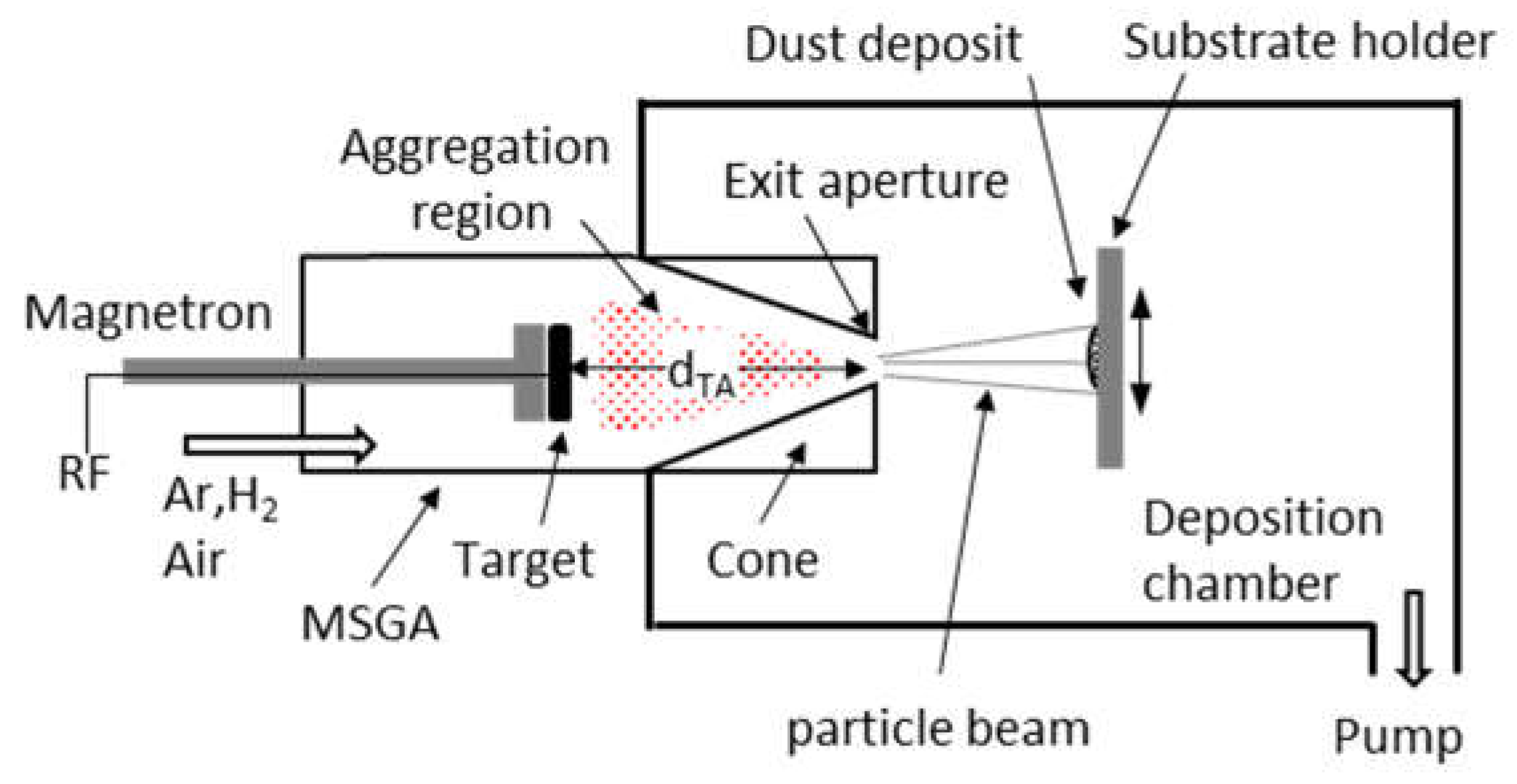
Figure 1 presents the experimental setup used for the production of W dust by magnetron plasma [
16,
17]. It consists of an MSGA cluster source (left) attached to a collection vacuum chamber (right). The magnetron is equipped with a 2” diameter and 1/8” thickness W target (99.95% purity from Lesker). The exit aperture, connecting the cluster source with the deposition chamber, has a diameter of 2 mm, while the length of the aggregation region (d
TA) is 90 mm. Due to the pressure difference between the MSGA (80 Pa) and the deposition chamber (5 Pa), the nanoparticles grown in the aggregation chamber are ejected through the exit aperture and are collected on the substrates. The sputtering process is performed using an RF (13.56 MHz) generator and an impedance matching box, the applied RF power being 80 W for all the deposited samples. Sole Ar or mixed with H
2 are used as process gases, both gases presenting a 6.0 grade purity. The influence of H
2 over the W NPs synthesis was investigated in a parametric study, in which the amount of H
2 injected in discharge was varied between 0-82% (i.e., the H
2[sccm]/(Ar[sccm]+H
2[sccm] ratio). During this parametric study, the pressure in the MSGA chamber was kept constant (80 Pa), to eliminate the influence of the increasing pressure over the W NPs synthesis process. To this purpose, while the H
2 mass flow rate was increased from zero up to 9.7 sccm, the amount of Ar mass flow rate was correspondingly diminished between 5.3 – 2.25 sccm. At 41 % hydrogen content in discharge, small amounts of synthetic air (0.01-0.5 sccm, i.e 0-5 %) were deliberately injected in discharge, again keeping the pressure constant by reducing correspondingly the Ar flow. The synthetic air used is a mixture of 79% N
2 and 21% O
2 and presents a 5.0 purity. The deposition duration was adapted for every sample, depending on the individual set of parameters deposition rates: 30 minutes for the samples with high deposition rates and up to three hours for those with lower deposition rates.
The deposition procedure requires some precautions, detailed in the following. We noted that using sole Ar as process gas, the deposition process starts with a high value, which decreases to a much smaller value in a short time interval (up to half of hour) [
18,
19]; this effect is related to the consumption of the residual gases in the aggregation chamber. Only after that, does the deposition take place only in Ar, without the influence of the residual gases. By tests, we identified that only H
2 is the atmospheric residual gas sustaining and enhancing the W NPs synthesis. For this reason, each time when the chamber was vented with atmospheric air, the W NPs were first deposited on a shutter until the deposition rate decreased to near zero. During this preparatory stage, the discharge was fed only with Ar. Only after this the desired amount of H
2 or air was injected in the discharge. In this way, only the W NPs deposited in conditions relevant to our study are collected on the substrate. The substrates consist of microscope glass slides (25 mm x 75 mm) or 011 Si substrates (10 mm x 10 mm) fixed on a holder which can be translated vertically, perpendicular to the nanoparticles beam, using a vacuum compatible translation stage. The substrates are placed 5 cm from the exit aperture. The dust collection rates were determined by weighing the collectors before and after dust deposition, using an electronic scale with 0.01 mg accuracy. The samples surface morphology was investigated using scanning electron microscopy (SEM). This analysis was conducted using an Apreo FEG High-Resolution Scanning Electron Microscope (HR-SEM), specifically the S LoVac model from Thermo Fisher Scientific Inc. in Hillsboro, OR, USA, and a Gemini 500 equipment from Zeiss (Oberkochen, Germany). The particle detection from SEM images was made by using a homemade Matlab program [
20], which can detect the particles in automatic mode. The program uses a 5-step calculation process, and the selection criteria of the particles are made by the radius range and the sensitivity value of the particle’s boundaries. In this line, the obtained statistics are based on the most detectable particles in the SEM images. The chemical composition of the tungsten nanoparticles was analyzed using X-ray Photoelectron Spectroscopy (XPS). We used a K-Alpha Thermo Scientific (ESCALAB™ XI+, East Grinstead, UK) spectrometer equipped with a 180° double-focusing hemispherical analyzer. To calibrate the peak positions, we used the adventitious C1s peak at 284.8 eV as a reference, indicated by Avantage data software (Thermo Avantage v5 9921, East Grinstead, UK). Surface elemental composition was determined by recording survey spectra at a pass energy of 50 eV. For the evaluation of elemental bonding states, high-resolution spectra for the binding energy regions of C1
s, O1
s, N1
s, and W4
f were measured at a pass energy of 20 eV. The acquisition and processing of spectra were performed using the Avantage data software mentioned above.
3. Results and Discussions
The experiments performed in this work provide information on the W dust (W NPs) deposition rate, the dimension of the deposited spot, dust size and morphology and its chemical composition.
3.1. Deposition Rates Evolution in the Presence of H2 Injected in Discharge and in the Presence of Air Leaks
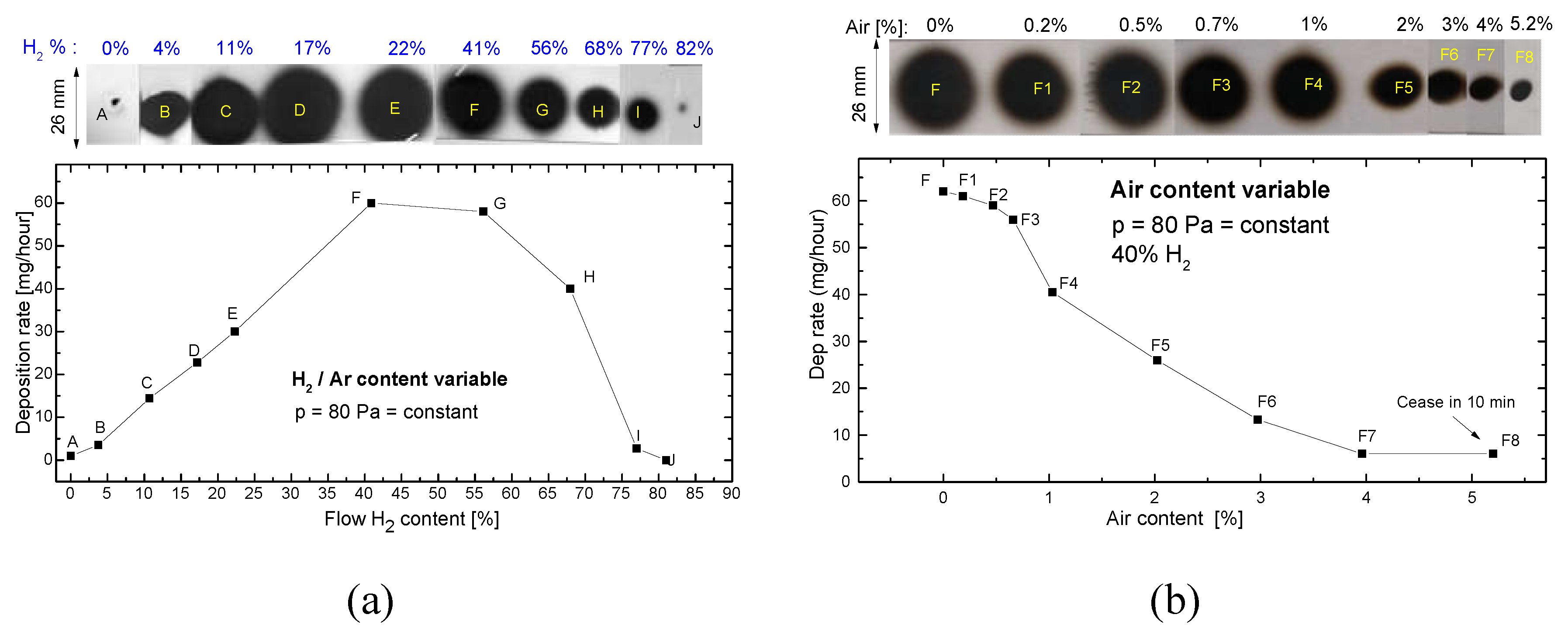
Figure 2 a present the evolution of the deposition rate and the deposited spot shape when the amount of H
2 in discharge is increased, the pressure being kept constant (80 Pa). We note that the deposition rate in sole Ar (point A) present a low value, around 1 mg/h. The deposition rates increase up to 60 times when the H
2 content is increased up to 40 % in discharge, even if the amount of Ar was gradually reduced to keep constant the pressure in the MSGA chamber.
For values of H2 content over 55 % the deposition rate is noted to decrease. Still, W dust is observed on the substrate even if H2 become dominant in discharge (up 82 % H2), the deposition rate being low but still not negligible (0.02 mg/hour). It is important to mention that for every experimental point (B-J) the deposition rate remains constant in time, proving that the presence of the H2 in discharge sustain continuously the synthesis of the W NPs.
The increase of the deposition rate when low amounts of H
2 are added in discharge was investigated recently by us [
18], being related to the presence in the discharge of new species namely the ArH
+ ions which enhance the target sputtering, leading to an increasing number of W species (atoms, ions) available for W NPs synthesis. In this range of H
2 content, the Ar ions has a reduced contribution to sputtering due to the symmetric charge transfer (SCT) between Ar and Ar
+: [
21]. SCT limits the energies of the Ar ions and neutrals, the Ar
+ ions being accelerated over small distances before being neutralized. We note that the variation tendency of the W NPs deposition rate (presented in
Figure 2a) is similar with that of the sputtering rate of thin films of Au in presence of H
2 (0-80%) mixed with Ar [
22]. Similar with the arguments presented in this work, the sputtering rate of W is most probable decreasing at high H
2 content in discharge due to the dissociation of the fast ArH
+ ions (for example via collision-induced dissociation [
23]. It results that the fast Ar ions and atoms will now be dominant and, due the SCT, the number of the sputtered W species will decrease, with a subsequent decrease of the W NPs synthesis rate.
Figure 2 b presents the evolution of dust synthesis rate in the presence of air leaks (collected dust spots F1-F8), compared with that obtained using 41 % H2 in discharge (spot F in both
Figure 2a,b). The increase in the amount of air leaks leads to a rapid decrease in the W dust synthesis rate. Again, the deposition rate remains constant in time for every experimental point up to 3% air in discharge (points F1-F7). The decrease of the deposition rate is natural to happen while the air leaks interact with the target surface, the resulting chemical compounds presenting a smaller sputtering yield when compared with the metallic W. Over 5% air, the deposition rate ceases in around 10 minutes (point F8 in
Figure 2 b); this behaviour is most probably due to the target poisoning.
One may observe that the W NPs spots obtained on the substrate present a maximum diameter of 2.6 cm, the method allowing the efficient coating of a microscope slides by translating the substrate in front of the MSGA cluster source.
3.2. Morphological Investigations of W NPs Obtained with Variable Amounts of H2 Injected in Discharge
The dust formation was assessed by examining the surface of Si collectors placed on the collector holder.
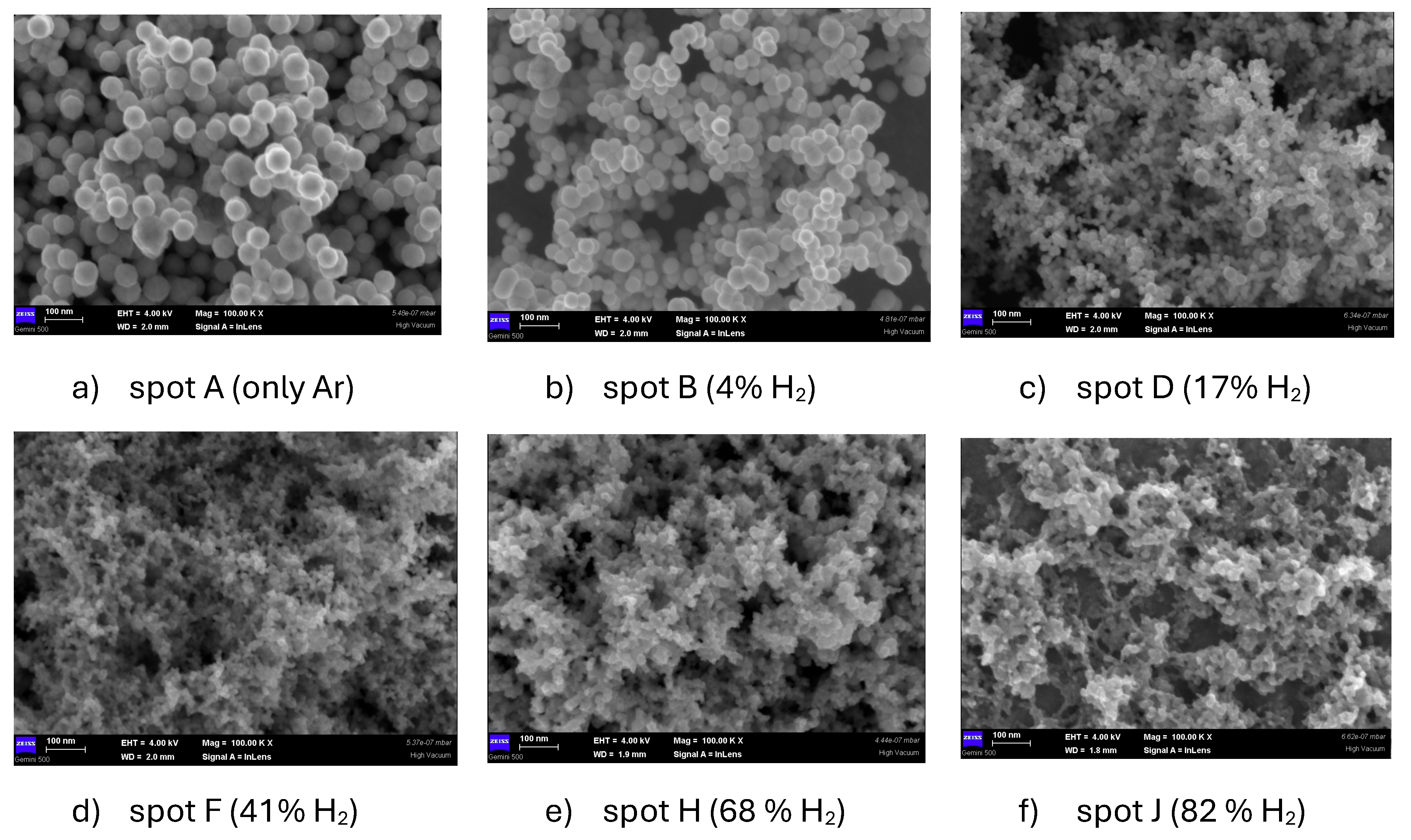
Figure 3 presents a series of SEM images describing the morphology of the particles at various H
2 amounts in discharge. It is visible that increasing the H
2 amount in discharge, the dust appearance changes from individual nanoparticles (in Ar-dominated atmospheres), to agglomerations of smaller nanoparticles (obtained in H
2 dominated atmospheres).
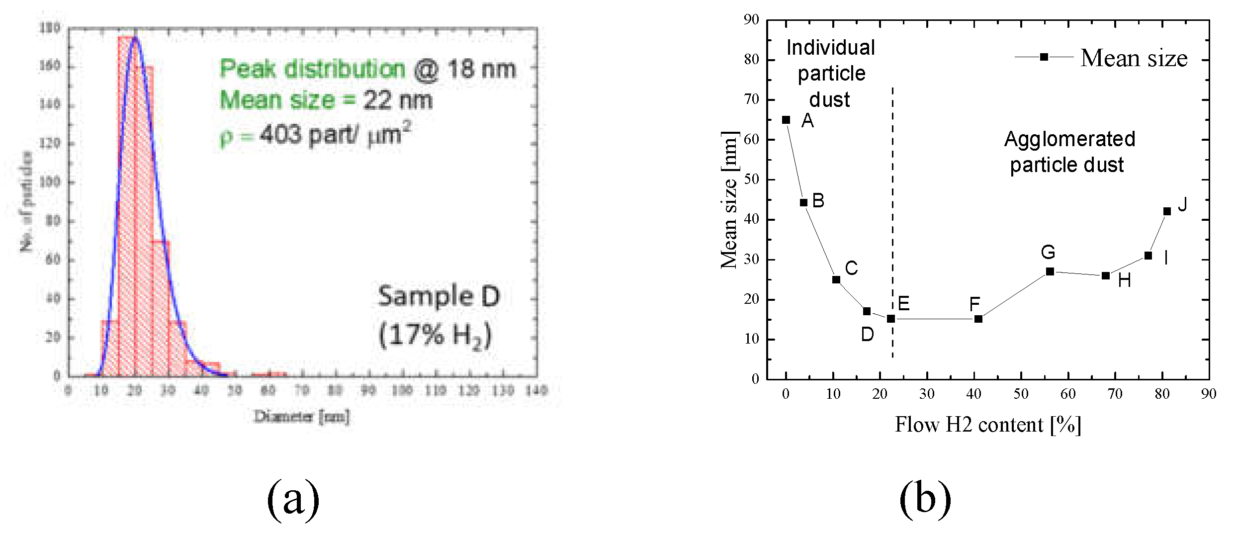
Figure 4a presents an example of the particle size distribution, obtained from the sample deposited with 17% H
2 content in discharge (sample D). In this line, the computational strategies were presented in reference [
20], and the resulting particle dimensions show an interesting behavior of the deposition process. Herein, by using a small amount of H
2, the mean size particle is around 56 nm (spot A), with a particle density of 280 part/μm
2. Increasing the H
2 content in the discharge, highlights a two-step threshold phenomenon. Mainly, by increasing the H
2 content (starting with spot B), the mean size of the tungsten particles, starts to decrease, from 41 nm (spot B) up to 15 nm (spot E). This could be considered the first particle mean size threshold. By continuing to increase the H
2 content (spot F), the mean size increases from 21 nm (spot F), up to 41 nm (spot J). This behavior could be considered as the second threshold. From this analysis, it can be easily identified the two major regions, in which the growth of the tungsten particles takes place under the H
2 influence. It is worth mentioning that, in the second growth region (from the spot F up to the J), the growth tendency of the particles is slow, rather expressing the tendency of nanoparticles to agglomerate and to form structures similar to film-like deposits. Usually, the deposits of nanoparticles produced by MSGA technique operated with Ar consist of individual nanoparticles, with a low degree of agglomeration, this being reported in many works like [
24].
The same characteristics are observed in W NPs samples obtained with low H
2 content. The tendency of nanoparticles to agglomerate at high H
2 content may be associated with the known mechanisms of nanoparticles growth: coagulation (joining together of two clusters), coalescence (growth of large clusters while the small clusters evaporate) and aggregation (solid clusters are joined due to their contact, while partially preserving their initial shape) [
25], these processes taking place in the aggregation space of the MSGA. On the other hand, it is not excluded that the agglomeration of the nanoparticles to take place at the substrate level, especially for the higher H
2 content in discharge (see
Figure 3f, for 82% H
2 content in discharge). This hypothesis requires supplementary investigations, being important for fusion related studies.
3.3. Morphological Investigations of W NPs Obtained with Air Leaks in Discharge
Figure 5 presents a series of SEM images describing the morphology of the particles at different amounts of air leaks injected in discharge: corresponding to the following spots from
Figure 2b: F3 (0.7% air), F4 (1% air) and F5 (2% air). The SEM image from
Figure 3d (spot F in
Figure 2a, corresponding to 41% H
2 in discharge, deposited in absence of air leaks) is the reference sample for this experiment. From
Figure 5a-c and
Figure 2a results that inserting air in discharge, the NPs tends to agglomerate, the dimension of the agglomerates increasing with air content. Moreover, at 2% air content, the dust deposit has the aspect of a continuous film. Of course, due to air leaks, their chemical composition must be altered.
3.3. Chemical Composition of the W dust. Influence of the Air Leaks
A comprehensive analysis of the chemical bonding in tungsten nanoparticles was performed using X-ray photoelectron spectroscopy (XPS) investigations. To this purpose were considered three samples obtained under different experimental conditions: i) using only Ar (spot A in
Figure 2a); ii) containing 41% H
2 in the Ar + H
2 mixture (sample F in
Figure 2a,b); iii) adding 0.5% air leak in discharge (sample F2 in
Figure 2b).
The survey spectra of these samples are presented in
Figure 6a, revealing that the primary elements present in the obtained nanoparticles are tungsten, oxygen and nitrogen. The spectra also show the presence of carbon, which is adventitious postdeposition contaminant (proven by the absence of the C-W bond from the C1
s high-resolution spectrum, which is not presented here). Compared to our previous results, the presence of N
2 in the sample using only Argon is unexpected; this is most probably due to the residual nitrogen coming from the gas supply system.
The detection of oxygen and nitrogen suggests the formation of tungsten oxides, nitrides and oxynitrides which could result from incorporation of these compounds during synthesis of the NPs (in the presence of air leaks or of the residual N
2) or on the NPs surface due to subsequent exposure to air (for all samples). Figures 6b,c present the high-resolution spectra of all examined samples in the W4
f, respectively N1
s spectral regions. The spectra in W4f region contains the following distinct doublets: metallic tungsten, with peaks at 31.3 eV (W4 f 7/2) and 33.4 eV (W4 f 5/2), tungsten dioxide WO
2, with peaks at 32.7 eV (W4f7/2) and 34.8 eV (W4f5/2), and tungsten trioxide WO
3, with peaks at 35.9 eV (W4f7/2) and 38.1 eV (W4f5/2). Supplementary, some peaks attributed to W-N and/or W-N-O bonds are expected to overlap (see
Figure 5b) within the W 4f spectrum, this preventing it proper deconvolution [
26]. Despite of this, the following qualitative remarks over the W4
f spectral region can be drawn. The spectra indicated in
Figure 6b show that the maximum amount of the metallic W can be found in the sample deposited in sole Ar. On the other hand, the contribution of WO
3 bonds increases with the addition of hydrogen and/or synthetic air in the plasma atmosphere, with a significant contribution when argon, hydrogen, and synthetic air are mixed. However, all samples, whether from plasma synthesis process or post synthesis nanoparticle exposure in the ambient environment, show a common tendency towards oxidation.
On the other hand, in the N1
s spectral region do not appear such overlapping, allowing the proper decomposition of this spectral region. As an example, in
Figure 6d is presented the deconvolution [
26] of the spectrum recorded in the N1
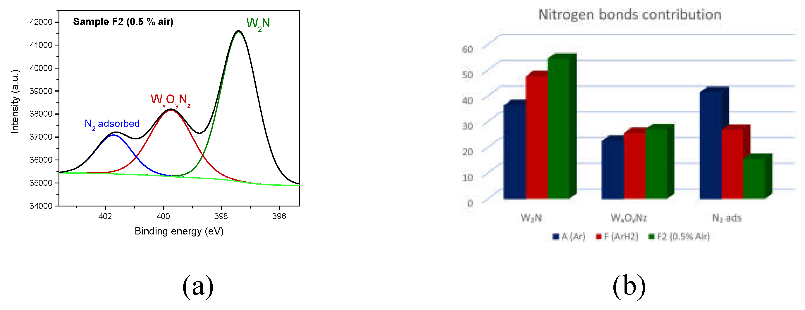
s region recorded for the sample F2 (deposited with 0.5 air leak in discharge): W
2N bond at 397 eV (contribution of 54.3%), WxOyNz bond at 399 eV (contribution of 27%) and nitrogen adsorbed on surfaces at 402 eV (contribution of 19%).
Figure 6e illustrates the relative contributions of different nitrogen bonds to the overall N1
s related XPS signal, depending on the gas used during the synthesis of tungsten nanoparticles. The processed data reveal that when a mixture of argon, hydrogen, and synthetic air is used as process gas, a pronounced contribution of tungsten nitride (W
2N) is note, while the amount of N
2 adsorbed on surfaces decreases. However, regardless of the synthesis conditions or exposure to a nitrogen rich environment after synthesis, all the samples consistently tend to form nitrogen based chemical bonds.
Figure 6e illustrates the relative contributions of different nitrogen bonds to the overall N1s-related XPS signal, depending on the gas used during the synthesis of tungsten nanoparticles. The processed data reveal that when a mixture of argon, hydrogen, and synthetic air is used as process gas, a pronounced contribution of tungsten nitride (W
2N) is note, while the amount of N
2 adsorbed on surfaces decreases. However, regardless of the synthesis conditions or exposure to a nitrogen-rich environment after synthesis, all the samples consistently tend to form nitrogen-based chemical bonds.
4. Conclusions
The results presented in this work show the possibility to produce tungsten dust (W NPs) using the MSGA method operated with totally different amounts of H2 injected in discharge. At low H2 content in discharge the deposition rate is strongly enhanced, this working regime being useful for application where high amount of W NPs with controlled dimension are necessary (for example in nanotechnology). When the MSGA discharge is dominated by H2, W dust is still produced, and this regime may be relevant to synthesis of nanometric dust in nuclear fusion devices. Supplementary, the presence of air leaks in discharge shows a complex change of nanoparticles morphology and chemical composition. Future studies will focus on increasing the maximum content in discharge and on studies regarding nuclear fuel retention in tungsten dust.
Author Contributions
Conceptualization, T.A., G.D.; Methodology, T.A., G.D.; Validation, T.A., G.D.; Formal analysis, T.A. V.M., V.S.; Investigation, E.M., A.B., V.S.; Data curation, E.M., A.B., V.M.; Supervision, G.D., Writing—original draft, T.A.; writing—review and editing, T.A, E.M., A.B., V.M., V.S. and G.D., project administration, G. D, T.A; funding acquisition, G. D., T.A. All authors have read and agreed to the published version of the manuscript
Funding
This research was funded by the European Union through the EURO fusion consortium and the Romanian Ministry of Research, Innovation and Digitalization.
Institutional Review Board Statement
Not applicable.
Informed Consent Statement
Not applicable.
Data Availability Statement
Data is contained within the article.
Acknowledgments
This work has been carried out within the framework of the EURO fusion Consortium, funded by the European Union via the Euratom Research and Training Programme (Grant Agreement No. 101052200—EURO fusion). Views and opinions expressed are however those of the authors only and do not necessarily reflect those of the European Union or the European Commission. Neither the European Union nor the European Commission can be held responsible for them. Part of this research was supported (or financed) by Romanian Ministry of Research, Innovation and Digitalization under Romanian National Core Program of the National Institute for Laser, Plasma and Radiation Physics LAPLAS VII–contract no. 30N/2023 and of the National Institute for Materials Physics, Project PC1-PN23080101.
Conflicts of Interest
The authors declare no conflicts of interest.
References
- Lassner, E.; Schubert, W.-D. Tungsten; Springer US: Boston, MA, 1999; ISBN 978-1-4613-7225-7. [Google Scholar]
- Pai, C.-F.; Liu, L.; Li, Y.; Tseng, H.W.; Ralph, D.C.; Buhrman, R.A. Spin Transfer Torque Devices Utilizing the Giant Spin Hall Effect of Tungsten. Appl Phys Lett 2012, 101, 122404. [Google Scholar] [CrossRef]
- Costa, M.; Costa, A.T.; Hu, J.; Wu, R.Q.; Muniz, R.B. β -Tungsten: A Promising Metal for Spintronics. Journal of Physics: Condensed Matter 2018, 30, 305802. [Google Scholar] [CrossRef]
- Abdelhameed, A.H.; Angloher, G.; Bauer, P.; Bento, A.; Bertoldo, E.; Canonica, L.; Fuchs, D.; Hauff, D.; Iachellini, N.F.; Mancuso, M.; et al. Deposition of Tungsten Thin Films by Magnetron Sputtering for Large-Scale Production of Tungsten-Based Transition-Edge Sensors. J Low Temp Phys 2020, 199, 401–407. [Google Scholar] [CrossRef]
- Filipescu, M.; Ion, V.; Colceag, D.; Ossi, P.M.; Dinescu, M. GROWTH AND CHARACTERIZATIONS OF NANOSTRUCTURED TUNGSTEN OXIDES; 2012; Vol. 64;
- Palla-Papavlu, A.; Filipescu, M.; Schneider, C.W.; Antohe, S.; Ossi, P.M.; Radnóczi, G.; Dinescu, M.; Wokaun, A.; Lippert, T. Direct Laser Deposition of Nanostructured Tungsten Oxide for Sensing Applications. J Phys D Appl Phys 2016, 49. [Google Scholar] [CrossRef]
- Filipescu, M.; Ossi, P.M.; Dinescu, M. WO x Cluster Formation in Radio Frequency Assisted Pulsed Laser Deposition. Appl Surf Sci 2007, 254, 1347–1351. [Google Scholar] [CrossRef]
- Dong, C.; Zhao, R.; Yao, L.; Ran, Y.; Zhang, X.; Wang, Y. A Review on WO3 Based Gas Sensors: Morphology Control and Enhanced Sensing Properties. J Alloys Compd 2020, 820, 153194. [Google Scholar] [CrossRef]
- Zhu, J.; Wei, S.; Zhang, L.; Mao, Y.; Ryu, J.; Mavinakuli, P.; Karki, A.B.; Young, D.P.; Guo, Z. Conductive Polypyrrole/Tungsten Oxide Metacomposites with Negative Permittivity. The Journal of Physical Chemistry C 2010, 114, 16335–16342. [Google Scholar] [CrossRef]
- Marcu, M.; Preda, L.; Vizireanu, S.; Bita, B.; Mihai, M.A.; Spataru, T.; Acsente, T.; Dinescu, G.; Spataru, N. Enhancement of the Capacitive Features of WO3 Supported on Pristine and Functionalized Graphite by Appropriate Adjustment of the Electrodeposition Regime. Materials Science and Engineering: B 2022, 277, 115585. [Google Scholar] [CrossRef]
- Coman, L.G.; Marcu, M.; Acsente, T.; Vizireanu, S.; Satulu, V.; Dinescu, G.; Matei, E.; Spataru, T.; Spataru, N.; Preda, L. Hybrid Nanostructures Based on Vertically Graphenes Decorated with Tungsten Oxide Nanoparticles for Enhanced Capacitive Performance. Diam Relat Mater 2023, 139, 110316. [Google Scholar] [CrossRef]
- You, J.H.; Visca, E.; Barrett, T.; Böswirth, B.; Crescenzi, F.; Domptail, F.; Fursdon, M.; Gallay, F.; Ghidersa, B.-E.; Greuner, H.; et al. European Divertor Target Concepts for DEMO: Design Rationales and High Heat Flux Performance. Nuclear Materials and Energy 2018, 16, 1–11. [Google Scholar] [CrossRef]
- Winter, J.; Gebauer, G. Dust in Magnetic Confinement Fusion Devices and Its Impact on Plasma Operation. Journal of Nuclear Materials 1999, 266–269, 228–233. [Google Scholar] [CrossRef]
- Rosanvallon, S.; Grisolia, C.; Delaporte, P.; Worms, J.; Onofri, F.; Hong, S.H.; Counsell, G.; Winter, J. Dust in ITER: Diagnostics and Removal Techniques. Journal of Nuclear Materials 2009, 386–388, 882–883. [Google Scholar] [CrossRef]
- Arnas, C.; Campos, A.; Diez, M.; Peillon, S.; Martin, C.; Hassouni, K.; Michau, A.; Bernard, E.; Fedorczac, N.; Gensdarmes, F.; et al. Micron-Sized Dust and Nanoparticles Produced in the WEST Tokamak. Nuclear Materials and Energy 2023, 36, 101471. [Google Scholar] [CrossRef]
- Acsente, T.; Negrea, R.F.; Nistor, L.C.; Logofatu, C.; Matei, E.; Birjega, R.; Grisolia, C.; Dinescu, G. Synthesis of Flower-like Tungsten Nanoparticles by Magnetron Sputtering Combined with Gas Aggregation. The European Physical Journal D 2015, 69, 161. [Google Scholar] [CrossRef]
- Acsente, T.; Negrea, R.F.; Nistor, L.C.; Matei, E.; Grisolia, C.; Birjega, R.; Dinescu, G. Tungsten Nanoparticles with Controlled Shape and Crystallinity Obtained by Magnetron Sputtering and Gas Aggregation. Mater Lett 2017, 200, 121–124. [Google Scholar] [CrossRef]
- Tomy Acsente; Silviu Daniel Stoica; Cristina Craciun; Bogdana Mitu; Gheorghe Dinescu Enhancement of W Nanoparticles Synthesis by Injecting H 2 in a Magnetron Sputtering Gas Aggregation Cluster Source Operated in Ar, Submited to Plasma Chemistry and Plasma Processing.
- Acsente, T.; Gabriela Carpen, L.; Matei, E.; Bita, B.; Negrea, R.; Bernard, E.; Grisolia, C.; Dinescu, G. Tungsten Nanoparticles Produced by Magnetron Sputtering Gas Aggregation: Process Characterization and Particle Properties. In Progress in Fine Particle Plasmas; IntechOpen, 2020.
- Valentina, M.; Anca, B. Proceedings of the International Scientific Conference SEA-CONF Algorithm-Based Methods as Information Source for Plasma-Material Interaction Studies-an Overview Algorithm-Based Methods as Information Source for Plasma-Material Interaction Studies-an Overview. 2021; 252–259. [Google Scholar] [CrossRef]
- Mason, R.S.; Allott, R.M. The Theory of Cathodic Bombardment in a Glow Discharge by Fast Neutrals. J Phys D Appl Phys 1994, 27, 2372–2378. [Google Scholar] [CrossRef]
- Budtz-Jørgensen, C.V.; Kringhøj, P.; Bøttiger, J. The Critical Role of Hydrogen for Physical Sputtering with Ar–H2 Glow Discharges. Surf Coat Technol 1999, 116–119, 938–943. [Google Scholar] [CrossRef]
- Bogaerts, A.; Gijbels, R. Effect of Small Amounts of Hydrogen Added to Argon Glow Discharges: Hybrid Monte Carlo–Fluid Model. Phys Rev E 2002, 65, 056402. [Google Scholar] [CrossRef]
- Kratochvíl, J.; Kuzminova, A.; Kylián, O.; Biederman, H. Comparison of Magnetron Sputtering and Gas Aggregation Nanoparticle Source Used for Fabrication of Silver Nanoparticle Films. Surf Coat Technol 2015, 275, 296–302. [Google Scholar] [CrossRef]
- Smirnov, B.M. Processes Involving Clusters and Small Particles in a Buffer Gas. Uspekhi Fizicheskih Nauk 2011, 181, 713. [Google Scholar] [CrossRef]
- Kamiura, Y.; Umezawa, K.; Teraoka, Y.; Yoshigoe, A. Characterization of Polycrystalline Tungsten Surfaces Irradiated with Nitrogen Ions by X-Ray Photoelectron Spectroscopy. Mater Trans 2016, 57, 1609–1614. [Google Scholar] [CrossRef]
|
Disclaimer/Publisher’s Note: The statements, opinions and data contained in all publications are solely those of the individual author(s) and contributor(s) and not of MDPI and/or the editor(s). MDPI and/or the editor(s) disclaim responsibility for any injury to people or property resulting from any ideas, methods, instructions or products referred to in the content. |
© 2024 by the authors. Licensee MDPI, Basel, Switzerland. This article is an open access article distributed under the terms and conditions of the Creative Commons Attribution (CC BY) license (http://creativecommons.org/licenses/by/4.0/).
