
Submitted:
27 June 2024
Posted:
03 July 2024
You are already at the latest version
Abstract
Lithium-ion batteries have gained immense popularity in electric vehicles(EVs) due to their high energy density, offering an extended driving range. This has made them the preferred choice in the automotive industry, driving the shift towards EVs. However, alongside their popularity, safety concerns have arisen. The main issues include the potential for thermal runaway leading to fires or explosions, which can occur due to overcharging, physical damage, or manufacturing defects. While safety features and rigorous testing aim to mitigate these risks, ongoing research and development focus on enhancing safety measures to further ensure the reliability and safety of lithium-ion batteries in EVs. This paper focuses on the development and deployment of a real-time monitoring dashboard for Li-ion battery health monitoring using STM32 Microcontroller within the framework of Industry 4.0. Leveraging advanced sensor technology and data analytics, the dashboard provides continuous, comprehensive insights into battery performance, including state of charge and temperature. Integrating with Industry 4.0 principles, such as IoT, the system enables predictive maintenance, optimizing production processes and ensuring efficient utilization of resources. The implementation showcases the integration of real-time monitoring tools for Li-ion batteries, aligning with the transformative paradigms of Industry 4.0 to enhance operational efficiency and reliability within industrial settings.
Keywords:
lithium ion battery
; electric vehicle
; battery management system
; Internet of Things
; State-of-Charge
1. Introduction
Lithium-ion (Li-Ion) batteries are rechargeable batteries which can maximize battery lifespan and at the same time increase power energy density. They outlast the lifespan of traditional batteries, such as Nickel Metal Hydride (NiMH). Hence they have become quite popular [1,2,3,4,5,6]. Especially, they are quite successful in the application of autonomous mobile robots, which require long battery life during search and rescue missions [7,8,9,10,11,12]. Moreover, with the advent of machine learning and its ability to optimize the features, as a very low cost memory wise solution. Battery life can be optimized using state-of-the-art machine learning techniques [13,14,15,16,17,18]. Accordingly, a significant factor in improving EV performance is handling the management and estimation issues for the essential states of lithium-ion batteries. Estimating the state of charge (SOC) in lithium-ion batteries is a crucial issue to satisfy safe use and better battery management. Evaluation and monitoring of battery health, safety, and reliability are performed through the Battery Management System (BMS), in which the State of Charge (SOC) and temperature are fundamental parameters. SoC represents a measure of the battery remaining capacity, compared to the fully charged capacity. During a battery lifespan, its capacity decays even if it is not used, due to inter- nal aging processes. Due to this phenomenon, performances decrease and the battery is typically no longer considered reliable after a 20% fading in its nominal value. Therefore, Maximal releasable capacity estimations are essential to reduce safety risks and to prevent critical failures, allowing for appropriate battery replacement.
The direct open-circuit voltage (OCV) based method is straightforward and cost- effective. This approach works by assigning an SOC value for each value of the battery output voltage in the open-circuit state. Generally, the OCV-based method requires a few simple components to be implemented. However, obtaining an accurate OCV when the battery is under operation is not achievable for most batteries. Lithium-ion batteries need long relaxation time to obtain an accurate OCV after disconnecting the battery. Additionally, the OCV-based method is profoundly affected by the aging process of the battery. The current integrating (Coulomb counting) method can be used to calculate the descent or growth of an SOC based on the energy transferred from or to the battery. This method works efficiently for online SOC estimation.
This paper provides an overall outlook into the implementation of an efficient battery health and safety monitoring system that integrates IoT and advanced technologies inculcating Industry 4.0.
2. State-of-Charge
SOC is the ratio of the available charge capacity (also called capacity) of the battery ( to the capacity of a fully charged battery ( expressed in percentage.
SOC is an indication of the available charge in the battery at each moment. If the initial SOC is known, SOC at any instant can be estimated from the current drawn from the battery as:
where I is the load current and is the coulombic efficiency that is defined as the ratio of the charge delivered during discharge and the charge stored during previous recharge.
If there are no significant unwanted parasitic reactions in a Li-ion cell and the electrodes show no significant mechanical degradation, then the coulombic efficiency can be assumed as unity.
In electric vehicles (EVs), the state of charge (SOC) of lithium-ion batteries is crucial for determining how much driving range is available. By maintaining the SOC within optimal levels, the battery’s lifespan can be extended which ensures consistent performance over time.
Under ideal conditions, a 100% SOC indicates a fully charged battery whereas a 0% SOC indicates a fully discharged battery.
2.1. Method for Calculating SOC - Coulomb Counting
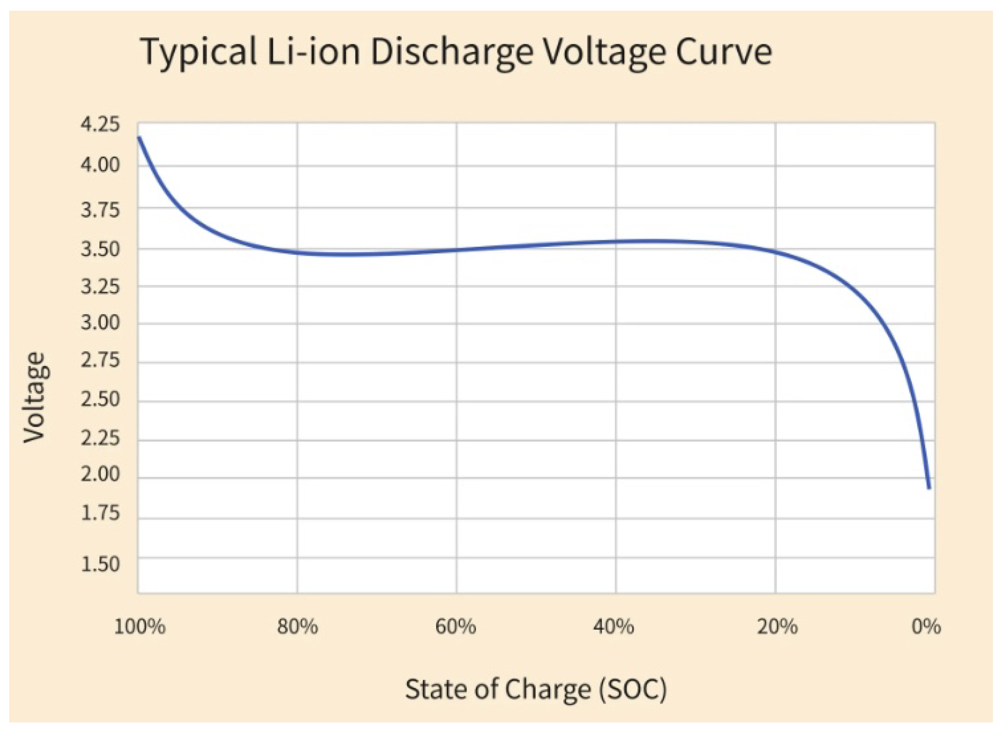
The most common method for calculating SOC is Open Circuit Voltage (OCV) Method. The OCV curve represents the relationship between battery voltage and SOC for a specific battery chemistry and temperature. Using the OCV method, the battery voltage is measured when it is at rest (no charge or discharge current flowing). However, during charging/discharging, voltage translation cannot be used to estimate SOC, since beyond a particular range of voltage, relation between SOC and voltage is non-linear.
On the other hand, Coulomb counting directly measures the charge/discharge current flowing into/out of the battery, providing real-time information about the amount of charge stored or consumed. Hence accurate values of SOC is obtained.
Figure 1.
Voltage vs SOC.
3. Methodology
3.1. Charging/Discharging of Li-Ion Battery
Charging
- Connect Battery: Plug the lithium-ion battery into the iMAX-B6 charger, ensuring correct polarity.
-
Start Charging: Initiate the charging process. The charger will follow the charging phases (CC, CV) automatically.Constant Current (CC) Phase: Charge at a constant current until a certain voltage is reached.Constant Voltage (CV) Phase: Hold the voltage steady while the current decreases.
- Monitor Parameters: Keep an eye on the charger display to observe current, voltage, and temperature readings. The iMAX B6 typically provides real time data.
- Charge Termination: The charger should automatically stop charging when the battery reaches the set voltage or when a certain amount of time has elapsed.
Discharging
- Connect Load: Connect a suitable load or iMAX-B6 charger/ discharger to the battery output for discharging.
- Start Discharging: Initiate the discharging process. Monitor the charger display for real-time information.
- Monitor Parameters: Keep an eye on the current, voltage, and temperature readings during the discharge process.
- Discharge Termination: The charger should automatically stop discharging when the battery reaches the set voltage or when a certain amount of time has elapsed.
3.2. Sensing of Current, Voltage and Temperature
To sense current, voltage, and temperature:
- Current Sensing: Use a current sensor in series with the battery. This current sensor is to be calibrated. For that, 1A current is passed through the sensor which read 0.038.
- Voltage Sensing: Measure the voltage across the battery terminals. A voltage divider is used as a voltage sensor by creating a circuit with two resistors in series to divide the input voltage down to a level that can be safely measured by a microcontroller.
- Temperature Sensing: Employ a temperature sensor placed near the battery.
3.3. Data to STM
- Connect Sensors: Connect the output of the current, voltage and temperature sensors to the corresponding analog input pins on the STM32.
- Analog to Digital Conversion: The analog values are converted into digital values using edge computing technique of STM.
- To Matlab: The values are then transferred to matlab which are obtained in the range of 0-1. These values are then multiplied by the gain for obtaining the actual values of current/voltage.
- Data Processing: The sensed data is then processed and involves filtering, averaging, or applying algorithms for the calculation of SOC.
3.4. Matlab
- Installion of Support Package: The STM32 support package is installed from the Add-Ons Explorer within MATLAB.
- Setting Up of STM32F411RE Nucleo Board: Connection of STM32F411RE Nucleo board to computer is done using a USB cable.
- Simulink: Create a new Simulink model. From the Simulink Library Browser, the necessary blocks are dragged and dropped onto the model to configure the communication with the STM32F411RE board.
- Configuration of Parameters: The parameters of STM32 blocks are configured according to the requirements.
- Connection of Blocks: The blocks are connected to define the flow of data and control between the STM32 board and other components of the system.
- Build and Deploy: After the model is ready, initiation is done to generate the code for the STM32F411RE board. Then, the code is deployed to the board using the appropriate options in Simulink.
- Run the Model: After deploying the code, Simulink model is run. MATLAB then communicates with the STM32F411RE board and execute the specified tasks.
- Results: The behaviour of the system is analysed by visualizing the data collected from STM which includes current, voltage, temperature and SOC variations in real time.
3.5. Display of Information
Matlab generated data including SOC, current, voltage and temperature are displayed in real-time. Further set up can be done to display this information in the form of a dashboard and made available in the mobile phones of EV users using advanced technologies.

Table 1.
Component Specifications.
| No. | Components | Specifications |
|---|---|---|
| 1 | Li-Ion Battery | 12V , 20Ah |
| 2 | Charger/Discharger | iMAX-B6AC |
| 3 | Current sensor | 30 Amps, ACS712 30A |
| 4 | Voltage sensor | Voltage Divider |
| 5 | Temperature sensor | Thermistor |
| 6 | STM32 MCU | Nucleo board F411RE |
| 7 | Perforated hardboard | - |
4. STM32 MCU Nucleo Board F411RE
The STM32F411RE is a 32-bit microcontroller with a 100 MHz ARM Cortex-M4 core, 512 KB Flash memory, 128 KB SRAM, various digital and analog peripherals, ADC, communication interfaces, timers, low-power modes, and support for development tools. It is an Arduino-compatible STMicroelectronics board. It offers a powerful and flexible platform for prototyping and developing various applications using STM32F411RE microcontrollers.
STM32 microcontrollers excel in edge computing, combining processing power with low power consumption for real-time, low-latency data handling at the edge. The integration in edge devices enables on-device computation, analysis, and data pre-processing, optimizing system performance in IoT, industrial automation, and sensor networks.
Figure 2.
STM32 MCU Nucleo Board F411RE.
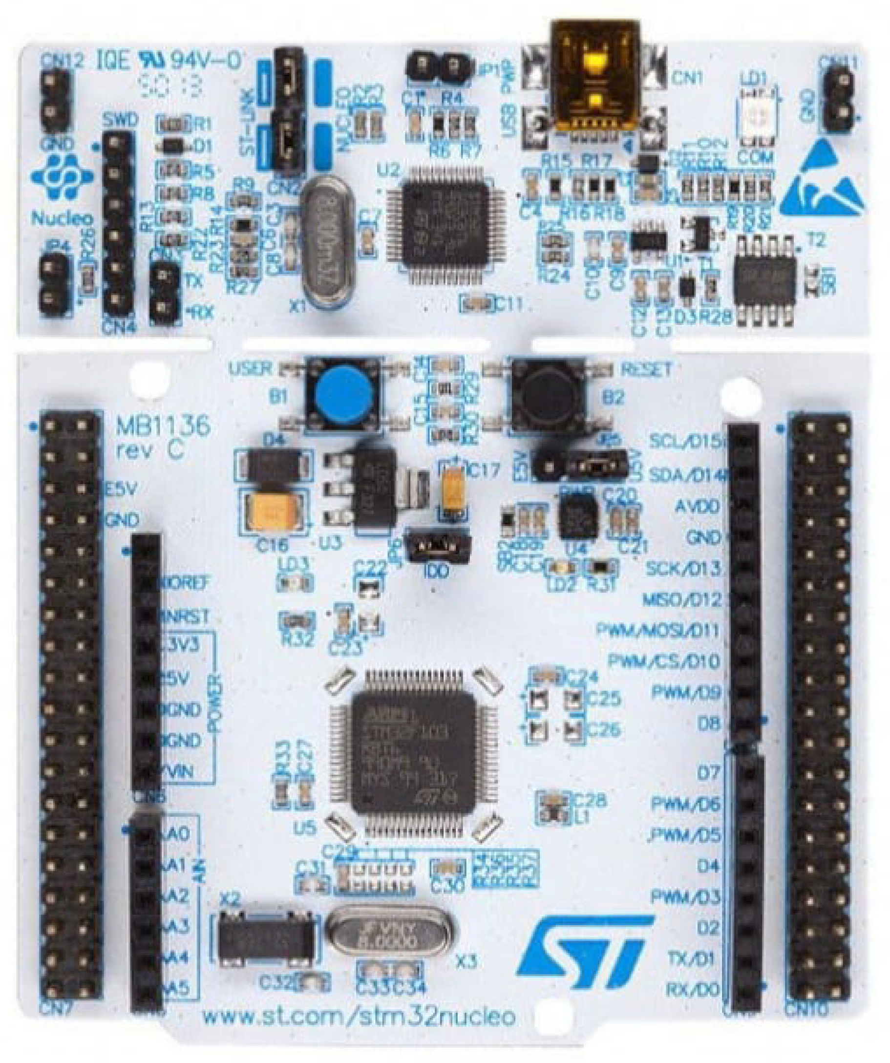
Features Some key features of STM32 Nucleo board are:
- Microcontroller: The STM32 Nucleo F411RE is built around the STM32F411RE MCU, which belongs to the ARM Cortex-M4 family. It operates at a clock frequency of up to 100 MHz.
- Memory: It typically has 512 KB of Flash memory and 128 KB of RAM, providing sufficient resources for a wide range of embedded applications.
- Integrated Debugger/Programmer: The Nucleo board includes an ST-Link debugger/programmer, allowing for easy programming and debugging of the STM32 MCU.
- Expansion Options: The board features Arduino Uno V3 connectors, making it compatible with a variety of Arduino shields. Additionally, it has ST Morpho extension headers for accessing the MCU’s peripherals.
- Power Supply: The board can be powered through a USB cable or an external source. It also has a built-in ST-LINK/V2-1 for programming and debugging via USB.
- Peripherals: The STM32F411RE MCU on this Nucleo board comes with a variety of peripherals, including GPIO, UART, SPI, I2C, ADC, and more, making it versatile for different applications.
- Integrated Development Environment (IDE): You can use the STM32CubeIDE or other compatible development environments to program and develop applications for the STM32 MCU on this Nucleo board.
- Community and Documentation: STMicroelectronics provides extensive documentation, datasheets, and user manuals for the STM32 Nucleo F411RE. Additionally, there is an active community of developers and users who share knowledge and experiences related to this development board.
5. Simulink Model
Figure 4 shows the simulink model.
5.1. Flowchart
Figure 3 shows the flowchart of the method adopted.
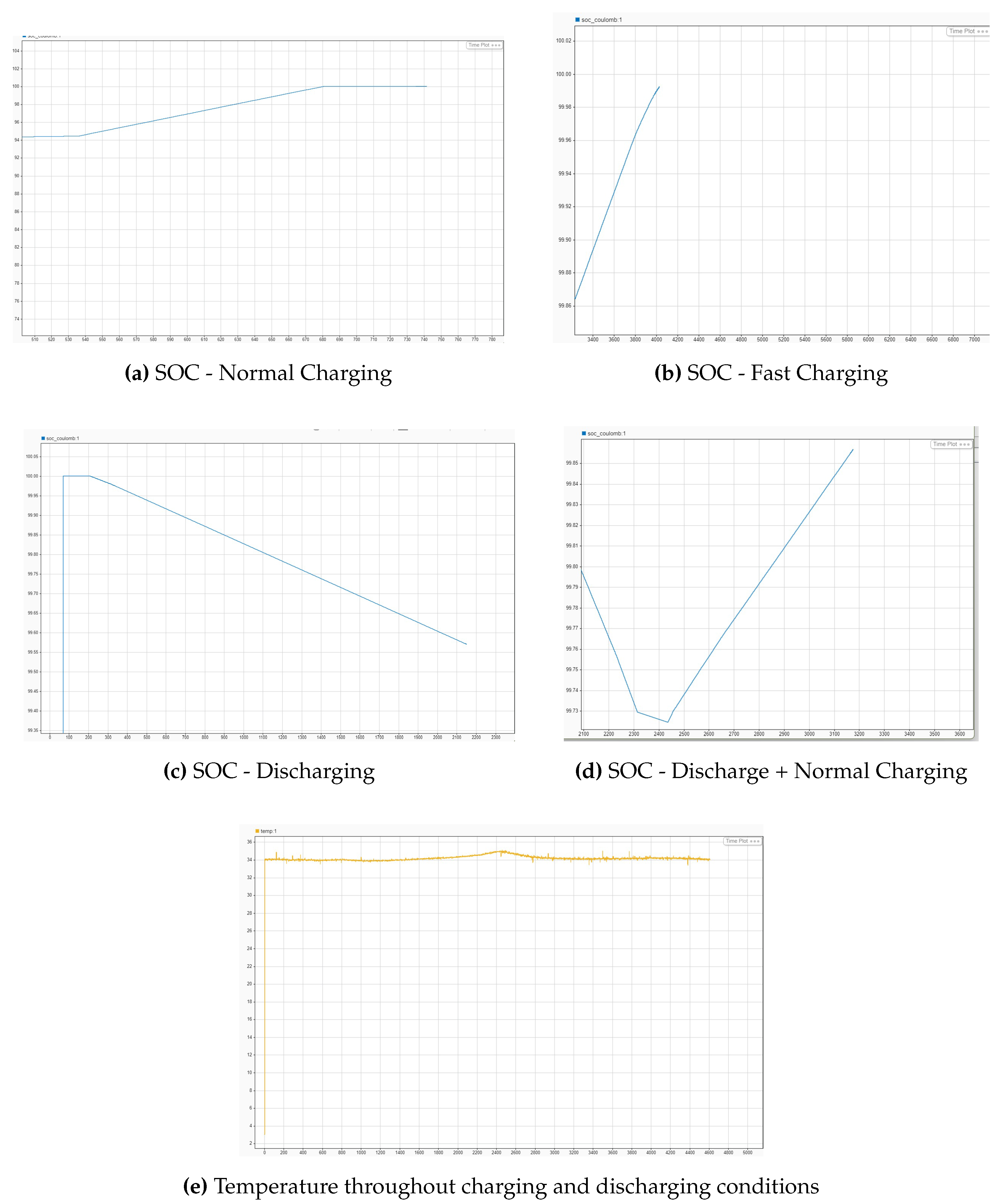
6. Results
Figure 5 shows SOC variations during charging/discharging conditions.
7. Result Analysis
Table 2.
Normal Charging.
| No. | Time(s) | SOC(%) | Temperature(C) |
|---|---|---|---|
| 1 | 2450 | 99.7284 | 34.1 |
| 2 | 2660 | 99.7676 | 34.2 |
| 3 | 2900 | 99.809 | 34.4 |
| 4 | 3197 | 99.8634 | 34.9 |
Table 3.
Fast Charging.
| No. | Time(s) | SOC(%) | Temperature(C) |
|---|---|---|---|
| 1 | 2450 | 99.7218 | 33.9 |
| 2 | 2660 | 99.774 | 34.029 |
| 3 | 2900 | 99.8337 | 34.094 |
| 4 | 3197 | 99.9067 | 34.104 |
Table 4.
Discharging.
| No. | Time(s) | SOC(%) | Temperature(C) |
|---|---|---|---|
| 1 | 1410 | 99.998 | 34.010 |
| 2 | 1650 | 99.927 | 34.142 |
| 3 | 1900 | 99.853 | 34.246 |
| 4 | 2306 | 99.7316 | 34.725 |
Inference
- Here the partial charging/ discharging of the battery has been done and the variation of SOC and temperature with time has been tabulated.
- From the tables, it can be seen that there are no significant variations in the temperature of the battery. It is around 34∘ C. However there is a slight increase during extended charging/ discharging hours. External factors and internal factors can also contribute to temperature rise of the battery.
- The SOC is found to increase during charging and decrease during discharging.
8. Conclusion
Considering the various safety concerns associated with the Li-ion batteries of EVs, the design of a real-time health monitoring system for lithium-ion batteries, within the context of Industry 4.0, has been set up, representing a significant advancement in the management of energy storage systems. This system is planned to seamlessly integrate cutting-edge technologies and data analytics to ensure efficient, and intelligent monitoring of battery health.
The system employs state-of-the-art sensors and communication protocols to continuously gather real-time data from Li-ion batteries. There is seamless data exchange between devices, enabling swift decision-making and preventive actions. Through the incorporation of sophisticated algorithms and data visualization techniques, the system provides real-time insights to industry professionals to anticipate potential issues, optimize performance, and extend the overall lifespan of Li-ion batteries. The principles adopted ensure scalability and adaptability to evolving technological landscapes and the system’s integration with the industrial IoT enables remote monitoring and management, fostering a more agile and responsive approach to battery health maintenance. To summarise, the designed system not only meets the demands of real-time health monitoring for Li-ion batteries but also facilitates a proactive and data-driven approach to battery management, ultimately contributing to enhanced safety, reliability, and efficiency in energy storage systems.
9. Future Scope
The use of electric vehicles are increasing day by day. Hence, the manufacturers are putting in dire efforts towards ensuring their safety while in use. This paper which includes the real-time monitoring and analysis of the safety parameters of lithium-ion battery can be further clubbed with a dashboard that can be accessed by the user from any location and is even capable of providing warning signals or safety measures in case of anomalies. For this, the data that we have obtained through the process can be used to train the microcontroller using artificial neural networks to detect anomalies and notify the users or manufacturers.
References
- Amin Bavand, Ali Khajehoddin, Masoud Ardakani, and Ahmadreza Tabesh, "Online Estimations of Li-Ion Battery SOC and SOH Applicable to Partial Charge/Discharge", IEEE Transactions on Transportation Electrification, VOL. 8, NO. 3, 2022.
- Erik Schaltz, Daniel-loan Stroe, Kjeld Norregaard, Lasse Stenhoj Ingvardsen, and Andreas Christensen, "Incremental Capacity Analysis Applied on Electric Vehicles for Battery State-of-Health Estimation ",IEEE Transactions on Industry Applications, VOL. 57, NO. 2, 2021.
- Yumeng Fu, Jun Xu, Mingjie Shi and Xuesong Mei "A Fast Impedance Calculation-Based Battery State-of-Health Estimation Method", IEEE Transactions on Industrial Electronics, VOL. 69, NO.7,JULY 2022.
- Jichao Hong, Zhenpo Wang, Changhui Qu, Fei Ma, Xiaoming Xu, Jue Yang, Jinghan Zhang, Yangjie Zhou, Tongxin Shan, and Yankai Hou, "Fault Prognosis and Isolation of Lithium-Ion Batteries in Electric Vehicles Considering Real-Scenario Thermal Runaway Risks", IEEE Journal of Emerging and Selected Topics in Power Electronics, VOL. 11, NO. 1, 2023.
- Ruixin Yang, Rui Xiong, Weixiang Shen “On-board Diagnosis of Soft Short Circuit Fault in Lithium-ion Battery Packs for Electric Vehicles Using an Extended Kalman Filter”, CSEE Jornal of Power and Energy Systems, VOL. 8, NO. 1, 2022.
- Mahammad, A. Hannan, MD. Murshadul Hoque, Aini Hussain, Yushaizad Yusof, Pin Jern Ker “State-of-the-Art and Energy Management System of Lithium-Ion Batteries i ikn Electric Vehicle Applications: Issues and Recommendations”, Special Section on Advanced Energy Storage Technologies and Their ApplicationsS, March 21, 2018.
- Zaheer, S. , Gulrez, T., & Thythodath Paramabath, I. A. "From Sensor-Space to Eigenspace – A Novel Real-Time Obstacle Avoidance Method for Mobile Robots". IETE Journal of Research, 68(2), 1512–1524, 2019. [CrossRef]
- Zaheer, S. , & Gulrez, T. "A Path Planning Technique For Autonomous Mobile Robot Using Free-Configuration Eigenspaces". International Journal of Robotics and Automation (IJRA), 6(1), 14, 2015.
- Zaheer, S. , Jayaraju, M., & Gulrez, T. "Performance analysis of path planning techniques for autonomous mobile robots". In 2015 IEEE international conference on electrical, computer and communication technologies (ICECCT) (pp. 1-5). IEEE. 2015.
- Gulrez, T. , Zaheer, S., & Abdallah, Y. "Autonomous trajectory learning using free configuration-eigenspaces". In 2009 IEEE International Symposium on Signal Processing and Information Technology (ISSPIT) (pp. 424-429). IEEE.
- Aravindan, A. , Zaheer, S., & Gulrez, T. (2016, September). "An integrated approach for path planning and control for autonomous mobile robots". In 2016 International Conference on Next Generation Intelligent Systems (ICNGIS) (pp. 1-6). IEEE.
- Zaheer, S. , Jayaraju, M., & Gulrez, T. (2014, March). "A trajectory learner for sonar based LEGO NXT differential drive robot". In 2014 International Electrical Engineering Congress (iEECON) (pp. 1-4). IEEE.
- Marken, R. , Kennaway, R., & Gulrez, T. (2022). "Behavioral illusions: The snark is a boojum". Theory & Psychology, 32(3), 491-514. [CrossRef]
- Gulrez, T., Kekoc, V., Gaurvit, E., Schuhmacher, M., & Mills, T. (2023, March). "Machine Learning Enabled Mixed Reality Systems-For Evaluation and Validation of Augmented Experience in Aircraft Maintenance". In Proceedings of the 2023 7th International Conference on Virtual and Augmented Reality Simulations (pp. 77-83).
- Satoshi, T. , Gulrez, T., Herath, D. C., & Dissanayake, G. W. M. (2005). "Environmental recognition for autonomous robot using slam. real time path planning with dynamical localised voronoi division". International Journal of Japan Society of Mech. Engg (JSME), 3, 904-911.
- Gulrez, T. , Tognetti, A., Yoon, W. J., Kavakli, M., & Cabibihan, J. J. (2016). "A hands-free interface for controlling virtual electric-powered wheelchairs". International Journal of Advanced Robotic Systems, 13(2), 49. [CrossRef]
- Zaheer, S. , & Gulrez, T. (2011, April). "Beta-eigenspaces for autonomous mobile robotic trajectory outlier detection". In 2011 IEEE Conference on Technologies for Practical Robot Applications (pp. 31-34). IEEE.
- Gulrez, T. , & Mansell, W. (2022). "High Performance on Atari Games Using Perceptual Control Architecture Without Training". Journal of Intelligent & Robotic Systems, 106(2), 45. [CrossRef]
Figure 3.
Simulink Model.
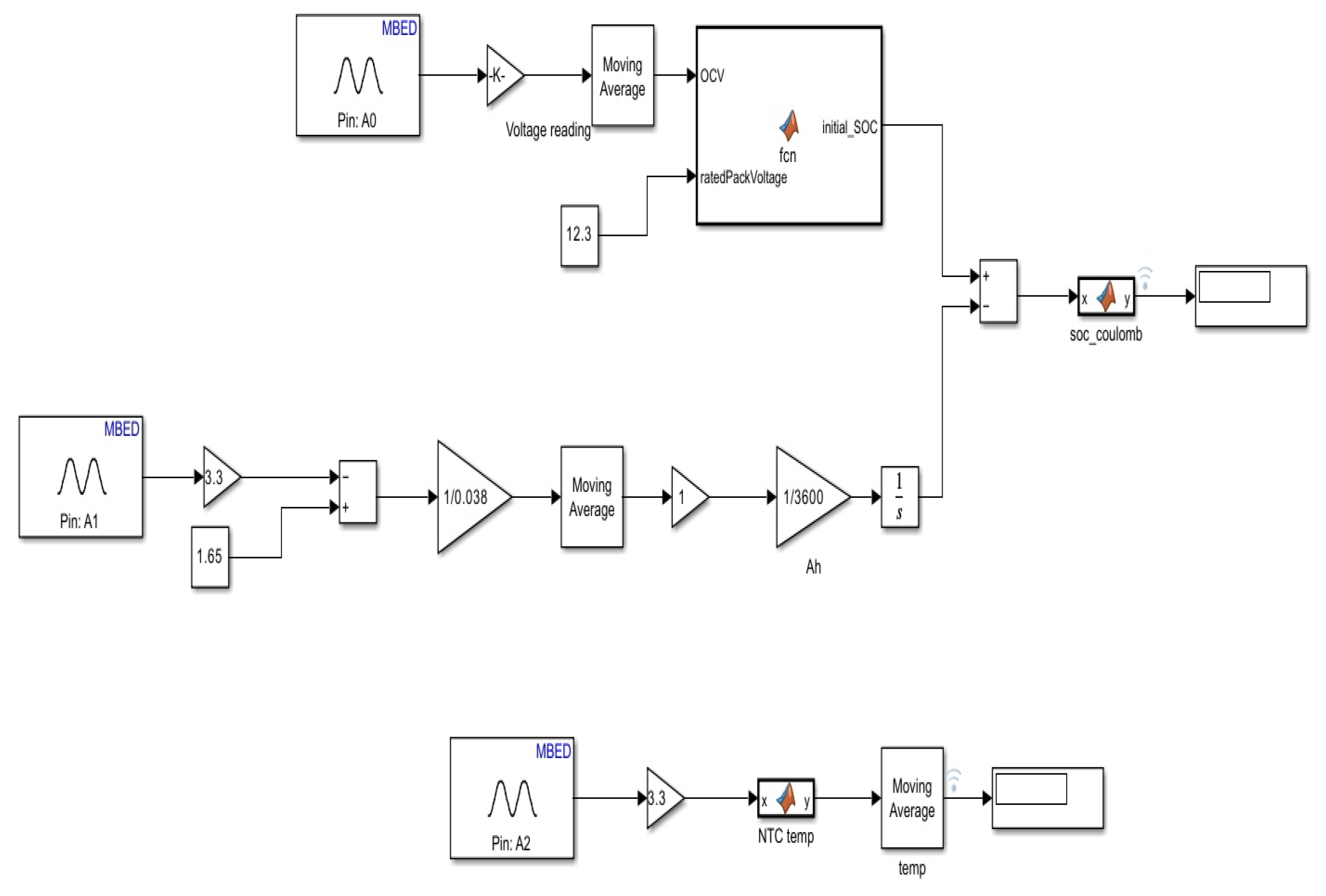
Figure 4.
Flowchart.
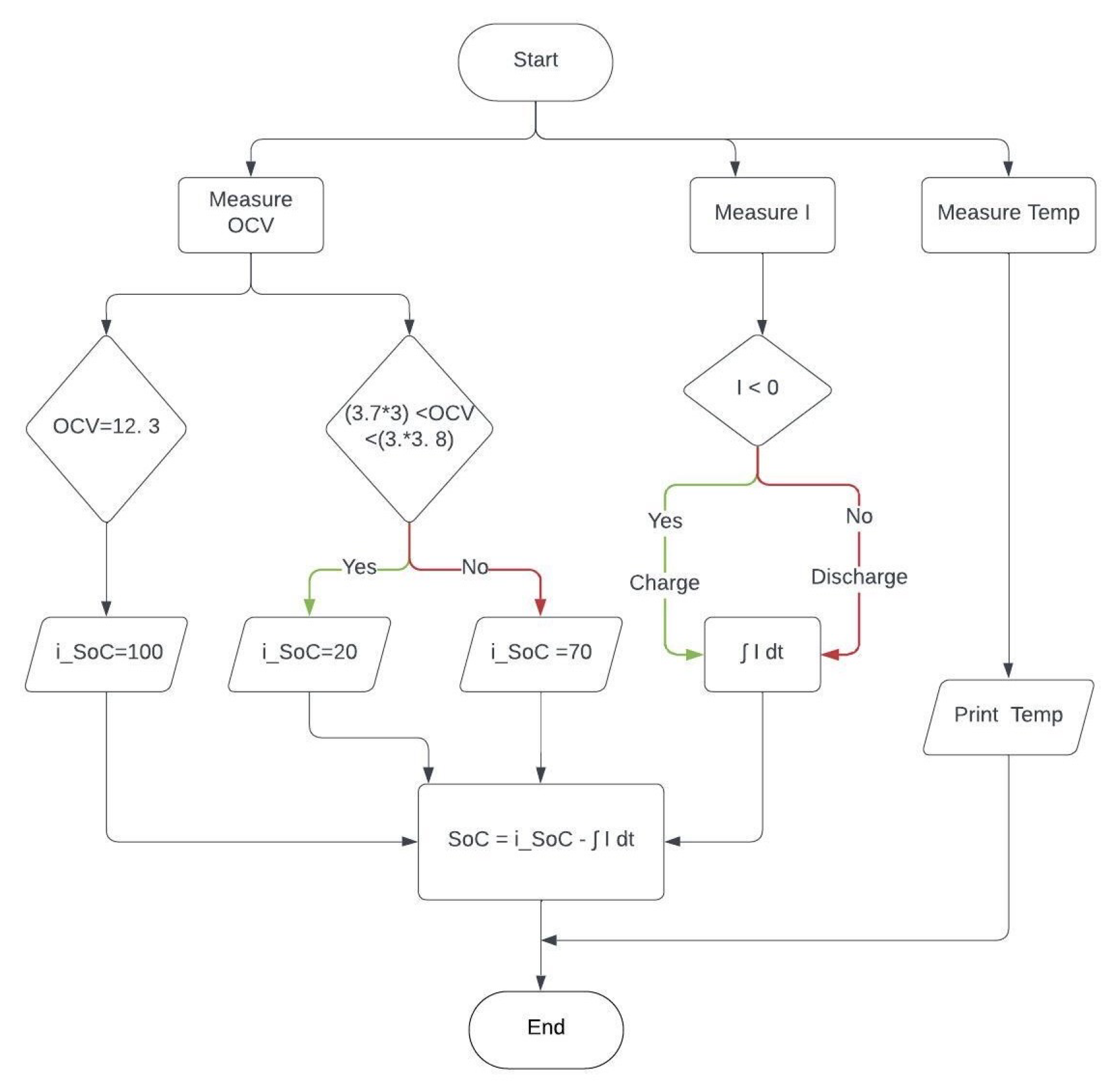
Figure 5.
SOC variations during Charging/Discharging Conditions
Disclaimer/Publisher’s Note: The statements, opinions and data contained in all publications are solely those of the individual author(s) and contributor(s) and not of MDPI and/or the editor(s). MDPI and/or the editor(s) disclaim responsibility for any injury to people or property resulting from any ideas, methods, instructions or products referred to in the content. |
© 2024 by the authors. Licensee MDPI, Basel, Switzerland. This article is an open access article distributed under the terms and conditions of the Creative Commons Attribution (CC BY) license (https://creativecommons.org/licenses/by/4.0/).
Copyright: This open access article is published under a Creative Commons CC BY 4.0 license, which permit the free download, distribution, and reuse, provided that the author and preprint are cited in any reuse.


