1. Introduction
Oil palm,
Elaeis guineensis Jacq. is the world’s most productive oil crops [
1] with average yield is about 4.26 ton per hectare [
2]. Among of the top four popular edible oils, palm oil is the most traded globally by roughly 40% of world supply [
3]. Palm oil is widely used for commercial products globally such as food, hygiene and chemical industry [
4]. Moreover, in the last decade, palm oil has been used in the production of biofuels, including in Indonesia [
5].
Oil palm can grow under a wide range of conditions, in mineral and peat soil, from flat to steep terrain. For mineral soil, the recommended slope terrain for oil palm is below 13.5°[
6]. However, [
7] reported that oil palm plantation mostly occurs in hilly and undulating terrain with slopes 10-20°. In addition to mineral soil, [
8] reported that around 1.7 million ha of Indonesia’s oil palm plantation is in peatland. Peat soil is characterized by low bearing capacity, low shear strength and high compressibility [
9,
10,
11].
Harvesting and transportation are the most crucial operations in the management of any crop plantation representing a substantial proportion of the labor cost of a plantation [
12]. About 15% of the fresh fruit bunch (FFB) production cost occurred in these operations [
13]. One of the important activities involved in FFB transportation is collecting and evacuating FFB from in-field to the collection bin or container bin. This collection bin will then be withdrawn by truck for onward transport to the mill.
For this activity, several equipment and machines have already been developed and applied in the plantation. Several options are manual wheelbarrow, wheeled and tracked transporter, and tractor with trailer. The selection of machines is based on the topography of the plantation and cost concern. Smallholders prefer small equipment, whereas large plantations prefer big machinery with high capacity.
In the application of wheelbarrow, [
14] reported that FFB evacuation by this equipment is low capacity and labor consumed as well as very hard-working leading to high risk of experiencing musculoskeletal disorders pain [
15]. Whereas a tracked machine is reported of being slow even it has good ability to work under wet conditions [
16]. In the application of tractor with trailer, [
12] reported that some technical problems arose such as soil compaction that agronomically lead to low growth of the root of the oil palm tree. Additionally, it also has a limitation where its usage is usually confined to the firm ground on flat and slightly undulating areas [
16].
In most cases, tracked type were used for oil palm harvester and transporter machine in a steep terrain [
17] of mineral soil. Instead of tracked type transporter, wheeled transporter with low ground pressure have been developed to be able traverse in either mineral or peat soil. The ability to work in low ground pressure is very important for machines that operate in peat soil since it has low bearing capacity [
18,
19]. Thus, a special design of agricultural machines is necessary to be developed to meet the allowable bearing capacity of peat or soft soil which should be lower than 100 kPa [
20,
21].
For this purpose, [
16] designed a six-wheel drive transporter powered with 23 HP water-cooled diesel engine. In 2020, [
12] continued to develop a six-wheel drive with four-wheel steering system transporter by using a bigger engine, i.e. 45.3 HP engine. The weight of the transporters (without load) was 1500 and 2750 kg, respectively. Those transporters could achieve productivity of 20 to 28 tons per day, respectively. Both designs could perform direct loading into a container bin by using a grabber. However, due to price concern, smallholders may not be able to afford big machines.
Several researchers have come up with lighter design of transporter and to satisfy the requirement of affordable price as well as ability for transporting general goods [
22]. A powered wheelbarrow with gasoline engine 4 HP, having carrying capacity of 300 kg and the productivity was 4 – 5 ton per day has been developed by [
22]. [
23] developed a compact transporter machine with single chassis, double sprocket and chain transmission, having carrying capacity of 300 kg and the productivity was 5-7 ton per day. However, those machines could not perform direct loading into a container bin.
Based on these considerations, a wheeled transporter with higher carrying capacity and able to perform direct unloading into a container bin needed to be designed. For this purpose, a transporter 6x6WD with a carrying capacity of 750 kg and employed scissor lift mechanism was developed.
2. Materials and Methods
2.1. Transporter Design
2.1.1. Design Criteria
The design criteria have been set to design a wheeled transporter that can traverse in peat soil, undulating terrain, higher carrying capacity and enable direct loading into a container bin. To meet this objective, the basic criteria of the FFB transporter were as follows: having maximum Ground Pressure (GP) 100 kPa, can be operated at steep terrain slope >20°, having carrying capacity 750 kg of FFB and able to dump load to the collecting bin with mechanism of hydraulic scissor lift.
2.1.2 Design Analysis
Maximum GP was derived as the ratio between the total weight of vehicle at full load with the contact surface area [
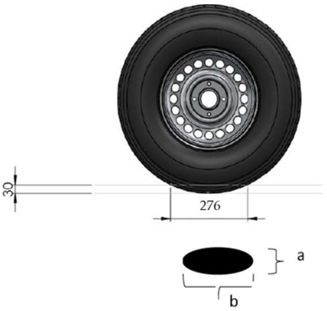
24]. GP was calculated at full load conditions in 4-wheel drive and 6-wheel drive. The contact surface area was calculated by assuming the wheel sinking to 30 mm. With this sinking (
Figure 1), the a was 216 mm and b was 276 mm.
The GP was equated as follow:
where GP – ground pressure, kPa; G – the vehicle weight at full load, kN; a – width of the contact area, mm; b – length of the contact area, mm; n – number of wheels.
To evaluate the stability and ability of transporter to traverse at steep terrain with slope >20° in different type of roads, the Center of Gravity (CoG) and maximum tipping angle of the transporter were calculated. The CoG was calculated based on the total weight of the transporter and moment acting on each transporter’s component. The calculation of CoG (Equation 2 and 3) [
13] was conducted at elevated bucket raised and at normal position in two levels of loads i.e., no load and full load. In this research, CoG was expressed in (x, y) coordinate system which expressed the longitudinal and lateral distance to the center of the rear axle.
where M
n – mass of each component, kg; x
n – the distance of the CoG of each component to the center of the rear axle at x-axis, mm; y
n – the distance of the CoG of each component to the center of the rear axle at y-axis, mm; x – the CoG of the transporter at x-axis, mm; y - the CoG of the transporter at y-axis, mm.
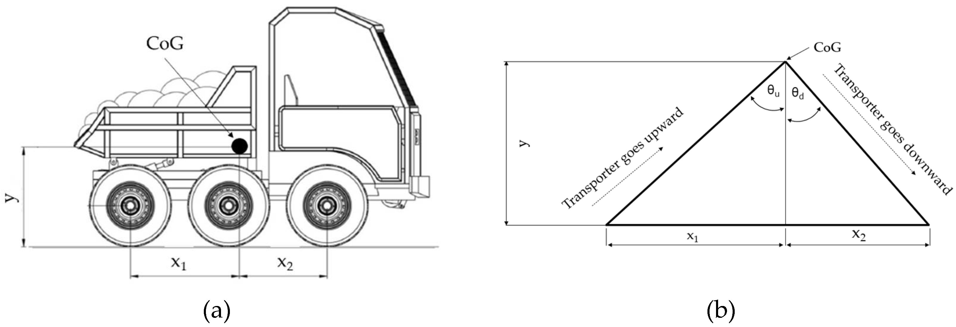
Afterwards, the maximum tipping angle was calculated by using trigonometric approach considering the CoG at full load (
Figure 2 and Equation 4,5) [
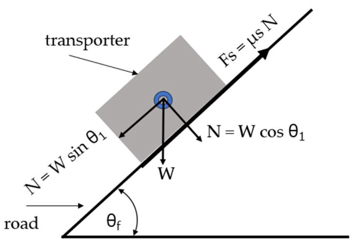
26] as well as considering the friction force of the different type of roads (
Figure 3, Equation 6).
where θ
u – tipping angle at upward position, °; x
1 – horizontal distance between the rear axle to CoG, mm; y – vertical distance between the bottom edge of rear wheel with CoG, mm; θ
d – tipping angle at downward position, °; x
2 – horizontal distance between the front axle to CoG, mm.
where θ
f – tipping angle based on the type of roads, °; μ
s- friction coefficient of the road.
The bucket tipping angle was designed to be 25.1° by considering the angle of repose of the FFB. Based on the measurement, the angle of repose of FFB was 20° which corresponds to the findings of [
27,
28] who reported that the dynamic angle of repose of FFB on mild steel varied from 18.59° to 26.29°.
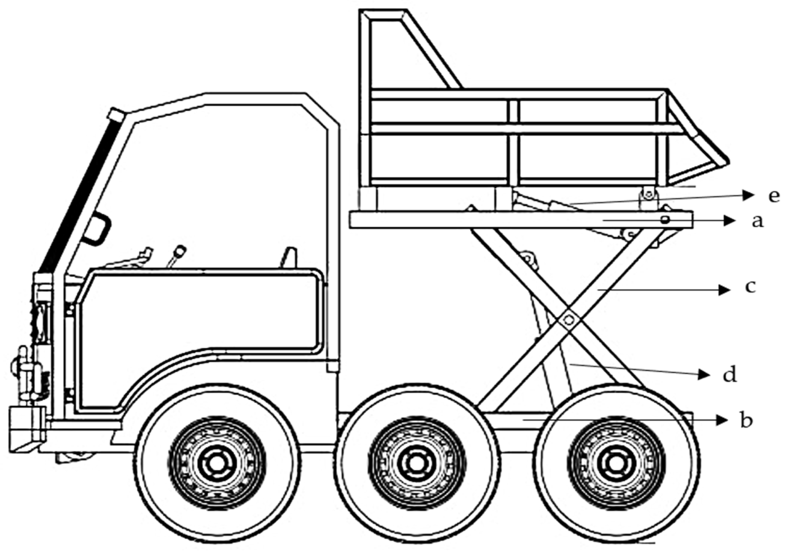
The ability to dump load directly to the collection bin was generated by the mechanism of hydraulic scissor lift (
Figure 4), which consisted of: a) top frame; b) bottom frame; c) arms to lift the top frame; d) actuator for hydraulic scissor lift; e) actuator for hydraulic dumper; f) hydraulic pump; g) control valve; h) hose and adaptor; and i) reservoir. The design was carried out optimally to enable the scissor lift to lift the bucket till at maximum load and dump the load to collecting bin. The rod diameter of the actuator was selected by plotting the force acting on the hydraulic cylinder, total length of the stroke and safety factor onto the Piston Rod Selection Chart [
29].
2.1.3. Transporter Components
All the components’ materials, including chassis, undercarriage, bucket, hydraulic scissor lift and operator cab were designed based on the optimized designed parameters. The three-dimensional design (3D) of the transporter component was developed by using Solidworks 2016 software. The construction material of the transporter used carbon steel S30C. Finite Element Analysis (FEA) was taken place to analyze stress conditions under different working conditions [
30] upon the transporter.
The materials for developing the prototype of the machine were selected based on the strength of the materials, availability, properties, machinability, affordability and economic considerations [
31].
2.2. Performance Evaluation
2.2.1. Drawbar Performance
The drawbar performance was carried out in three conditions of driven wheels namely six-wheels drive (6x6WD), four-wheels drive (4x4WD) and two-wheels drive (4x2WD). The 4x4WD transporter was set up by removing the middle wheels, while the 4x2WD was set up by also removing the connecting chain of front to middle wheels.
The transporter was set at gear 2 low transmission and 2200 rpm engine speed. A 30 hp four-wheels tractor was used to apply 5 level drawbar loads to the transporter. Drawbar pull was measured by using a tractive force drawbar load cell (Kyowa LTR-S-50KNSA1) and recorded in a handy strain meter (Kyowa UCAM-1A). The test was conducted on a grassy surface and the setup is shown in
Figure 5.
2.2.2. Steering Performance
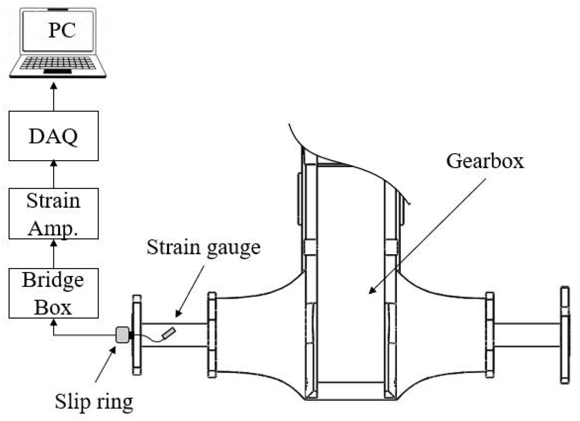
The steering performance test was conducted by evaluating the torque of the drive axle and the turning radius. The test of turning torque was conducted for transporter 6x6WD and 4x4WD on three different surfaces i.e., asphalt, concrete, and soil. The axle torque was sensed by using strain gages which were installed at the drive axle of the gearbox. Signal from strain gage was connected to Strain Amplifier Minebea DAS-406B with bridge Box Kyowa DB-120A. Output from strain amplifier was connected to minilab 1008 USB data acquisition (DAQ) and the data was recorded by PC. The instrumentation setup for steering performance test is shown in
Figure 6.
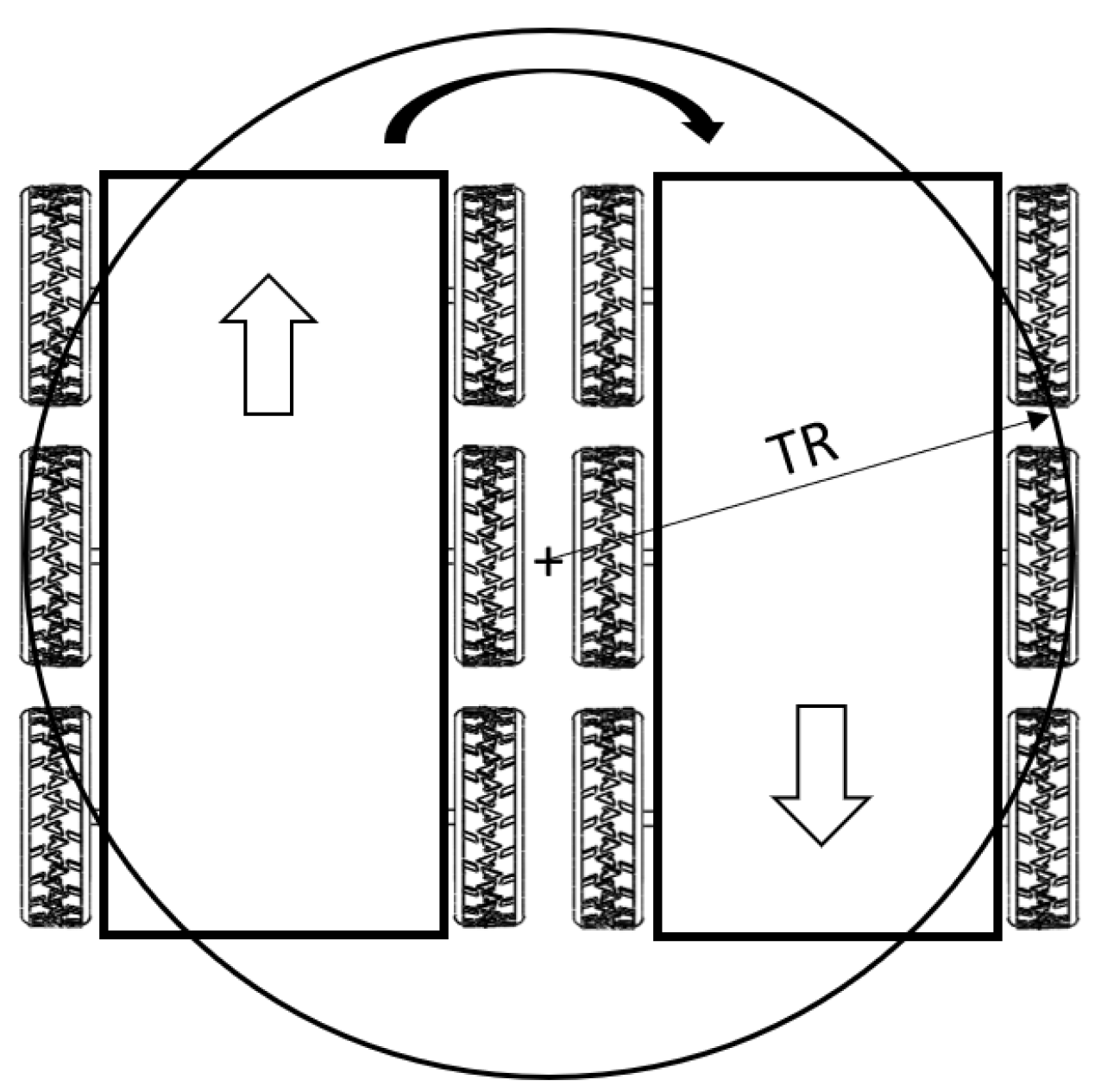
The turning radius was determined as the radius of outer wheel tread when the transporter performing 180° of turning (U-turn) and it was measured by metering tape as shown in
Figure 7. To perform U-turn, one side of wheels was powered while the other side was fully braked.
2.2.3. Hydraulic Scissor Lift Mechanism
The performance of hydraulic scissor lift mechanism was evaluated for unloading or dumping the designed loads in three parameters. The first was the rising time of the hydraulic scissor lift by using a stopwatch. The second was the pressure in hydraulic line by using a hydraulic pressure gauge. The loads applied in the bucket ranged from 0 kg, 250 kg, 500 kg and 750 kg. The third parameter was the temperature of the hydraulic oil which was observed by using analogue type hydraulic oil thermometer.
3. Results and Discussion
3.1. Design Result
3.1.1. Ground Pressure
One of considerations in developing the transporter was the ability to traverse in peat soil which is characterized by having low ground pressure and in mineral soil which is characterized by undulating and steep terrain. Hence a special-designed wheeled transporter was developed. In soft clay soil, the maximum allowable bearing capacity is 100 kPa [
34].
The tire used to develop the transporter was based on the availability of off-road tire found in the market. The tire specification was 27/8.5 R13. Based on Equation 1, the maximum ground pressure of 4x4WD and 6x6WD transporter is shown in
Table 1. To be able traverse in peat soil, the maximum GP shall be lower than the allowable bearing capacity (100 kPa), thus the transporter that suits the criteria was 6x6WD.
The ability of traversing in peat soil was indicated by the 6x6WD with GP 69.42 kPa. The small value of GP generated from this transporter was obtained from the even distribution of force acting on the transporter to the six wheels of the transporter. The utilization of 6-wheels drive also provides benefit to minimize slippage which may often occur in peat soil and in wet mineral soil (wet soil caused by rain).
3.1.2. Specification and CAD Drawing
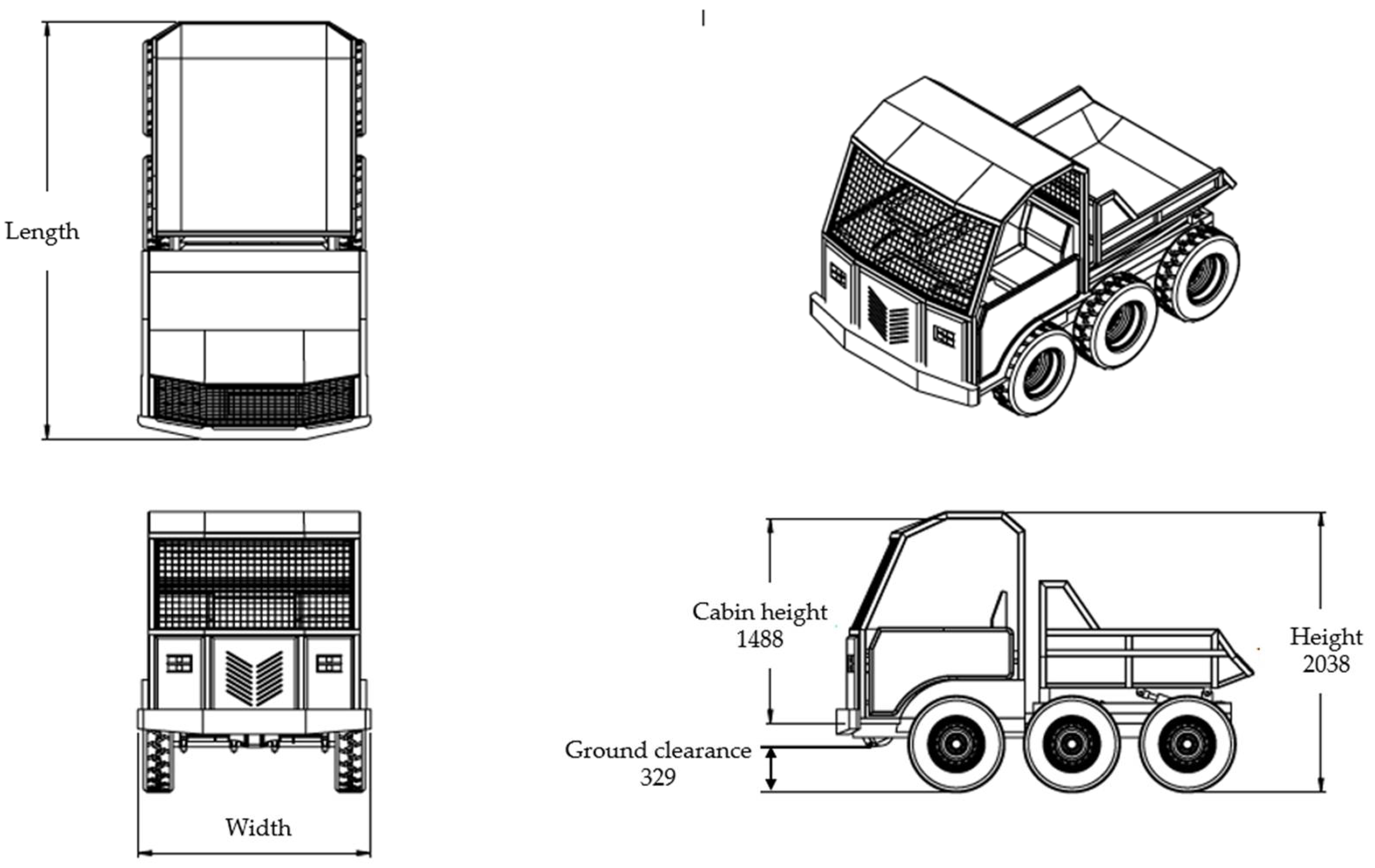
In order to understand the material strength of components used in this prototype, the FEA simulation was taken place to several transporter’s components that receive the biggest part of force, namely chassis, mounting gearbox, and mounting engine. Based on the simulation results, the von misses stress and displacement were below the allowable stress of steel carbon JIS S30C. The technical specification and CAD drawing of the 6x6WD transporter are shown in
Table 2 and
Figure 8.
3.2. Transporter Stability
3.2.1. Specification and CAD Drawing
After the 6x6WD transporter was selected, the stability of the transporter was one of the evaluations criteria that confirmed the design had ability to traverse in steep terrain which is commonly found in mineral soil. In this regard, a terrain slope of 20° was used as the minimum limit for the transporter not to tipping. To meet the requirement, the tipping angle that can be passed by transporter was evaluated from the CoG as well as based on the types of the roads.
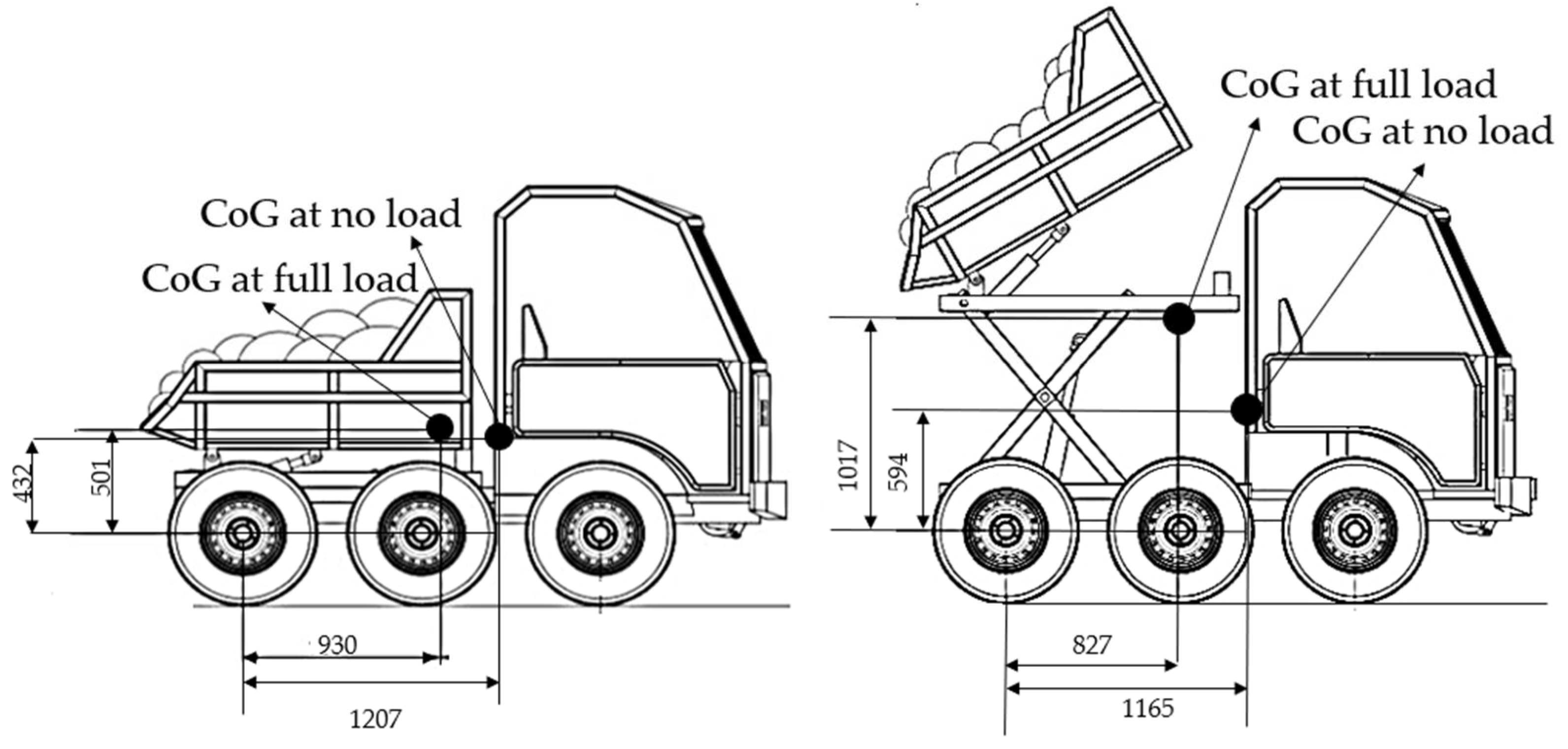
Based on the calculations of Equation 2 and 3, the CoG at normal and unloading positions are shown in
Table 3 and
Figure 9. The normal position represented the condition of transporter when traversing with full load or no load in the bucket, while the unloading position represented the transporter when unloading the FFB with the bucket tipping angle was 25.1°.
3.2.2. Tipping Angle
The maximum tipping angle was the maximum angle that can be passed by transporter without tipping. Based on the CoG coordinate (
Table 3) and Equation 4 and 5, the maximum tipping angle at upward, downward, and lateral position are shown in
Table 4.
To be able to travel on different types of roads especially on wet and dry soil, the maximum tipping angle at asphalt and soil road were also calculated by considering the friction force (
Table 5).
Based on
Table 4 and
Table 5, the tipping angle results were higher than the terrain slope (20°) as specified on the design criteria. Thus, the transporter was expected to have good stability.
3.3. Transporter Performance
3.3.1. Speed
The forward speed at 3 gears levels as resulted from performance test ranged from 0.38 to 2.58 ms
-1 while the reverse speed was 0.27 ms
-1 (
Table 6). These speeds were appropriate speed range for the in-field machinery operation for palm oil plantation, where the terrain is mostly poor condition.
3.2.2. Tractive Performance
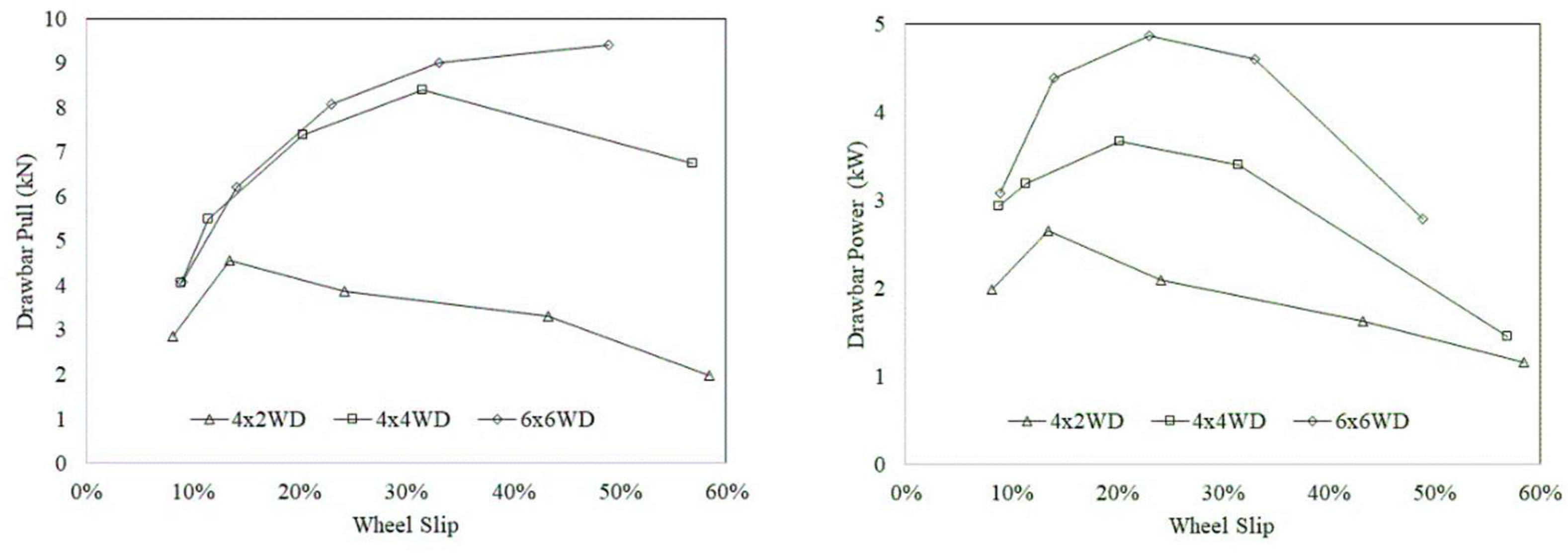
The tractive performance in terms of relation between drawbar pull and drawbar power at different wheel slips is shown in
Figure 10. The tractive performance graphs revealed that the transporter with 6x6WD achieved superior tractive performance compared with 4x4WD and 4x2WD. The transporter with 6x6WD provided the highest performance with the maximum drawbar pull was 9.41 kN which obtained at wheel slip 48.9% and the maximum drawbar power was 4.87 kW at wheel slip 23.0%.
3.2.3. Turning performance
The average turning radius at different transporter wheels setting is shown in
Table 7. It was found that 6x6WD transporter performed the smallest turning radius compared with others. It can be explained that 6x6WD transporter could result in higher tractive force because it had three driven wheels when performing turning operation. A transporter with 4x2WD showed the biggest turning radius because it only had one driven wheel to perform turning and it did not have adequate traction to turn the transporter.
The comparison of turning torque for 6x6WD and 4x4WD transporter on two different surfaces i.e., asphalt and soil is shown in
Table 7. From that data it was revealed that the transporter with 6x6WD had comparatively bigger axle torque compared with 4x4WD and it validated the explanation why 6x6WD has smaller turning radius compared with 4x4WD.
3.2.4. Hydraulic scissor lift performance
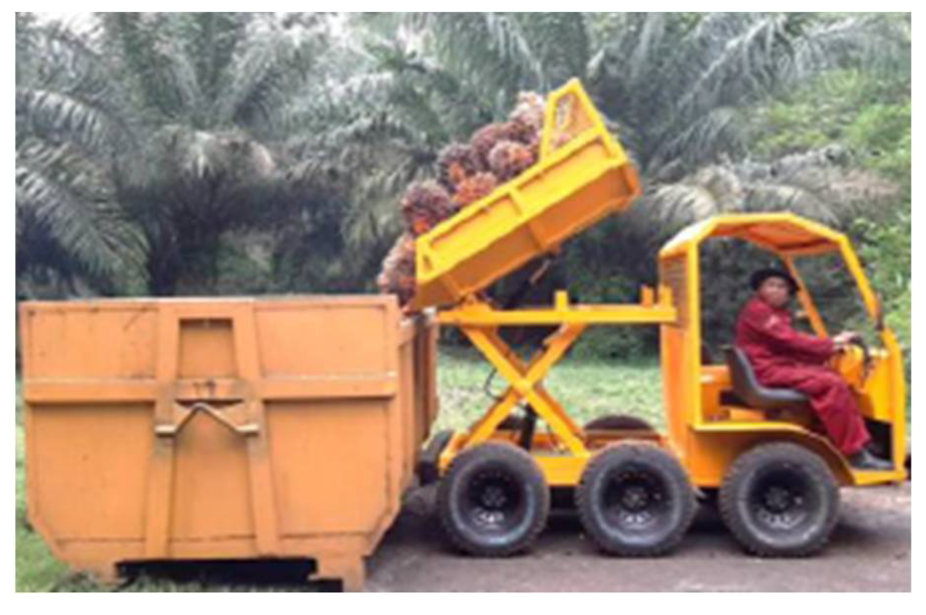
The unloading mechanism of the hydraulic scissor lift is shown in
Figure 11. In this picture, the transporter lifts the bucket till the maximum extrusion and dumps the FFB to the collecting bin. The performance is shown in
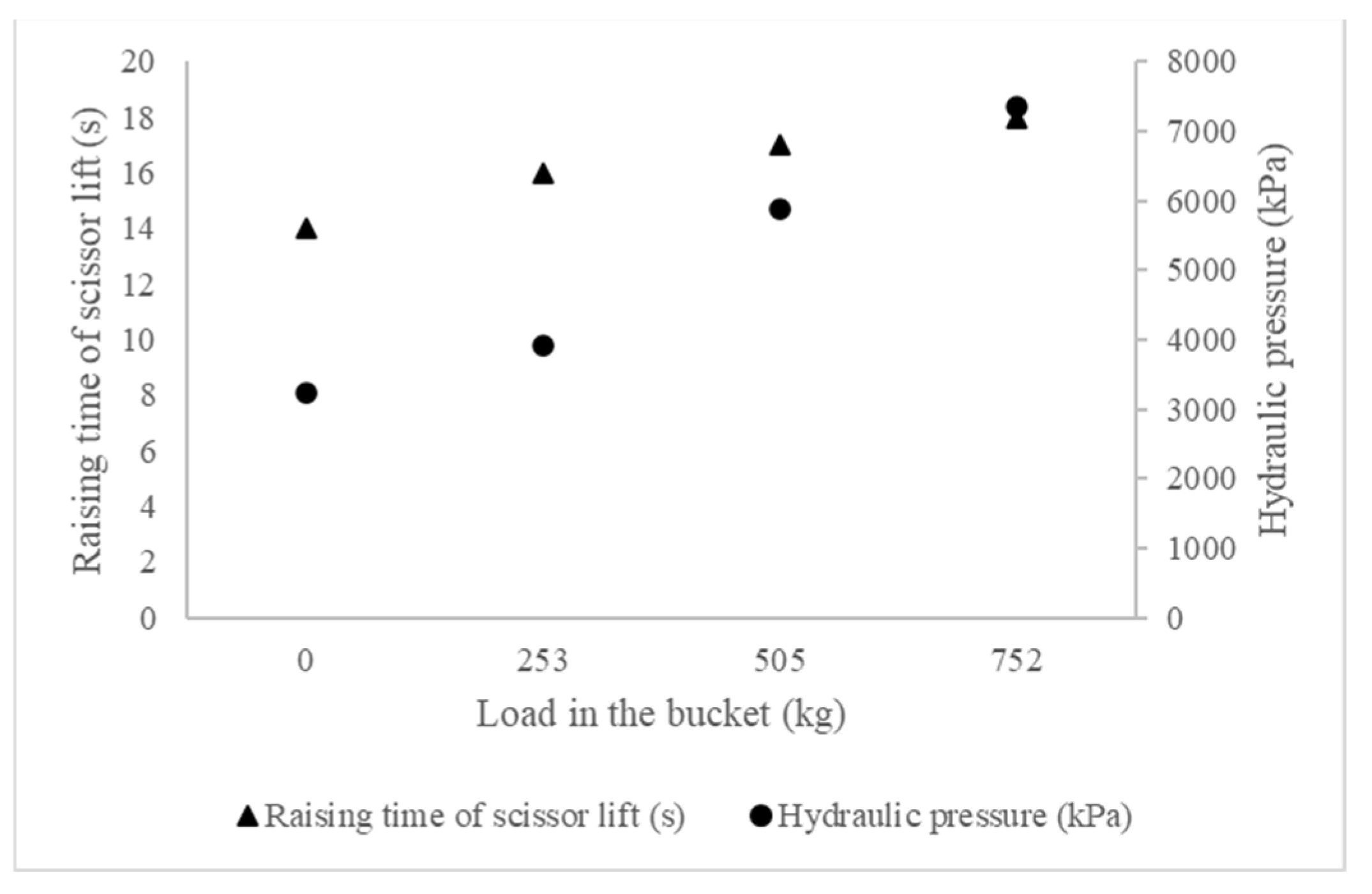
Figure 12. The rising time of the scissor lift increased with the increased load in the bucket and maximum rising time was 18.1 s at the highest load 751.7 kg.
Hydraulic pressure in the hydraulic system also increased with the increased load in the bucket. At the maximum load 751.7 kg, the hydraulic pressure was 7.35 MPa. This pressure was still below the maximum capacity of the hydraulic pump 12 MPa. The temperature of hydraulic oil was stable during the test with the maximum temperature was 56oC. This temperature was still lower than the allowable temperature of SAE 10W hydraulic oil used in the test.
3.2.5. Working capacity
The field working capacity or productivity of this transporter was 13-17 tons day
-1. The field working capacity depends on the maturity density and weight of FFB. Based on the field productivity result of the 6x6WD transporter and the secondary data of other FFB transporters performance, it could be concluded that this vehicle could increase 15 times of productivity than conventional (manual) wheelbarrow (
Table 8).
5. Conclusions
The objective of this research has been completed with the development of one unit prototype of 6x6WD transporter. Based on the design analysis, this transporter could traverse both in peat soil and mineral soil where palm oil is commonly grown in Indonesia. The designed transporter also had the advantage of direct evacuation of FFB from in-field to collection bin. The 6x6WD transporter could carry capacity up to 750 kg with the average productivity was 15 tons day-1. It was concluded that 6x6WD transporter designed in this research could increase working capacity up to 15 times than conventional (manual) wheelbarrow.
6. Patents
This 6x6WD transporter with scissor lift mechanism has been granted by Patent from the Ministry of Law and Human Rights of the Republic of Indonesia with Patent Number IDS000003776 Year 2021.
Author Contributions
Conceptualization, D., I. M. E., R. P. A. S., and A. S.; methodology, D., R. P. A. S., and A. S.; software, D., and R. P. A. S.; validation, D., R. P. A. S., and A. S.; formal analysis, D., R. P. A. S., and A. S.; investigation, D.; resources, D. and I. M. E.; data curation, D., I. M. E., R. P. A. S., and A. S; writing—original draft preparation, D., and I. M. E.; writing—review and editing, D., I. M. E., R. P. A. S., and A. S.; visualization, D., and I. M. E.; supervision, D.; project administration, D., and I. M. E.; funding acquisition, D., and I. M. E. All authors have read and agreed to the published version of the manuscript.
Funding
This research was funded by PALM OIL FUND MANAGEMENT AGENCY (BPDPKS), grant number PRJ-92/DPKS/2018, addendum number PRJ-2/DPKS/2019 and addendum number PRJ-32/DPKS/2019 and The APC was self-funded.
Data Availability Statement
All data are presented in this article in the form of figures and tables.
Conflicts of Interest
The authors declare no conflicts of interest.
References
- Goh, K.J.; Wong, C.K.; Ng, P.H.C. Oil palm. In Encyclopedia of Applied Plant Sciences, 2nd ed.; Thomas, B., Murray, B.G., Murphy, D.J., Eds.; Academic Press: USA, 2017; pp. 382-390. [CrossRef]
- Murphy, D.J.; Goggin, K.; Paterson, R.R.M. Oil palm in the 2020s and beyond: challenges and solutions. CABI Agric Biosci 2021, 2:39, 1-22. [CrossRef]
- Factbox: Global Edible Oil Markets Simmer After Shock Indonesia Ban. Available online: https://www.reuters.com/business/energy/global-edible-oil-markets-simmer-after-shock-indonesia-ban-2022-04-22/ (accessed on 24 August 2023).
- Villela, A.A.; Jaccoud, D.B.; Rosa, L.P.; Freitas, M.V. Status and prospects of oil palm in the Brazilian Amazon. Biomass and Bioenergy 2014, 67, 270-278. [CrossRef]
- Adiatma, J.C.; Prasojo, H. Critical Review on the Biofuel Development Policy in Indonesia; IESR: Jakarta, Indonesia, 2021.
- Firmansyah, M.A. Karakterisasi, kesesuaian lahan dan teknologi kelapa sawit rakyat di rawa pasang surut Kalimantan Tengah (Characterization, land suitability and technology of smallholders palm oil in tidal swampy area in Central Kalimantan, in Bahasa). Jurnal Penelitian Pertanian Terapan 2014, 14(2), 97-105.
- Rhebergen, T.; Fairhust, T.; Zingore, S.; Fisher, M.; Oberthur, T.; Whitbread, A. Climate, soil and land-use based land suitability evaluation for oil production in Ghana. Europ. J. Agronomy 2016, 81, 1-14. [CrossRef]
- Marwanto, S.; Hendri, J.; Salwati. Excessive Amount of Rainfall Decreases Oil Palm Yield on Well-Drained Peatland. IOP Conf. Ser. Earth Environ. Sci. 2021, 648, 012099. [CrossRef]
- Islam, M.S.; Hashim, R. Bearing capacity of stabilised tropical peat by deep mixing method. Aust. J. Basic & Appl. Sci. 2009, 3(2), 682-688.
- Hua, L.J.; Mohd, S.; Tajudin, S.A.H.; Mohamad, S.N.A.; Bakar, I.; Masirin, M.I.M.; Zainorabidin, A.; Mahmood, A.A.W. Construction of Infrastructure on Peat: Case Studies and Lesson Learned. MATEC Web of Conf. 2016, 47, 03014. [CrossRef]
- Dewi, R.; Hastuti, Y.; Sutejo, Y.; Iqbal, M.M.; Arfan, M. Peat soil improvement method using woven bamboo and cerucuk. Int. J. Adv. Sci. Eng. Inf. Tech. 2020, 10(4), 1617-1623. [CrossRef]
- Shuib, A.R.; Radzi, M.K.F.M.; Bakri, M.A.M.; Khalid, M.R.M. Development of a harvesting and transportation machine for oil palm plantations. J. Saudi Soc. Agric. Sci. 2020, 19(5), 365-373. [CrossRef]
- Henson, I. Ripening, harvesting, and transport of oil palm bunches. In Palm Oil; Lai, O.M., Tan, C.P., Akoh, C.C., Eds.; AOCS Press, 2012, 137-162. [CrossRef]
- Awaludin, A.; Salim, S.S.S.; Abidin, A.H.Z.; Ngah, M.R. Performance study of an oil palm fresh fruit bunch three wheeler evacuation machine. Onl. J. Sci. Tech. 2015, 5(2), 46-53.
- Nawik, N.S.M.; Deros, B.M.; Rahman, M.N.A.; Sukadarin, E.H.; Nordin, N.; Tamrin, S.B.M.; Bakar, S.A.; Norzan, M.L. Conceptual Design of Semi-Automatic Wheelbarrow to Overcome Ergonomics Problems Among Palm Oil Plantation Workers. IOP Conf. Ser.: Mater. Sci. Eng. 2015, 100, 012045. [CrossRef]
- Shuib, A.R.; Hitam, A. Performance of wakfoot as an in-field FFB transporter for soft ground and peat. Oil Palm Bulletin 2003, 46, 28-34.
- Matthies, D.; Wolf, B.; Kremer, J.; Ohrner, G. Comparative study of the impact of wheeled and tracked forest machines on soil and roots. In Austro2003: High Tech Forest Operations for Mountainous Terrain, Schlaegl, Austria, 5-9 October 2003.
- Agus, F.A.; Subiksa, I.G.M. Lahan Gambut: Potensi untuk Pertanian dan Aspek Lingkungan (Peatlands: Potency for Agriculture and Environmental Aspects), Balai Penelitian Tanah dan World Agroforestry Centre (ICRAF): Bogor, Indonesia, 2008.
- Aljawadi, R.A.M.; Ahmad, D.; Nawi, N.M.; Kassim, M.S.M.; Ismail, W.I.W. A review of the in-field transporting machines currently used in oil palm plantations in Malaysia. Basrah J. Agric. Sci. 2021, 34, 119-137. [CrossRef]
- Omar, R.C.; Jaafar, R. The Characteristics and Engineering Properties of Soft Soil at Cyberjaya. In Proceedings of the Geological Society of Malaysia Annual Geological Conference, Pulau Pinang, Malaysia, 8-9 September 2000.
- Shenbagavalli, M.; Jenitha, G.; Abirami, M.; Kalaiselvi, M. Experimental investigation of sub soil profile using GIS. Int. J. Civ. Eng. Tech. 2017, 8(2), 135-140.
- Hitam, A.; Deraman, M.S. Powered wheelbarrow: an implement to assist oil palm field activities. MPOB Information Series. 2001, 88.
- Deraman, M.S.; Hitam, A.; Shuib, A.R.; Mohamed, A. Compact transporter for in-field activities. MPOB Information Series. 2006, 316.
- Poršinsky, T.; Pentek, T.; Bosner, A.; Stankić I. Ecoefficient timber forwarding on lowland soft soils. In Global Perspectives on Sustainable Forest Management; Okia, C.A., Ed.; Intech Open, 2012, pp. 275-288.
- Meriam, J.L.; Kraige, L.G. Engineering Mechanics Statics, Fifth Edition. John Wiley & Sons, Inc.: United States of America, 2002, Volume 1, pp. 225-256.
- Royal Academy of Engineering. Available online: https://raeng.org.uk/media/phckgici/5-forces-centre-of-gravity-reactions-and-stability.pdf (accessed on 18 August 2023).
- Owolarafe, O.K.; Olabige, M.T.; Faborode, M.O. Physical and mechanical properties of two varieties of fresh oil palm fruit. J. Food Eng. 2007, 78(4), 1228-12232. [CrossRef]
- Morakinyo, T.A.; Bamgboye, A.I. Effects of age on some physical properties of oil palm fruitlets. Agri Eng Int. 2015, 17(3), 342-352.
- Parker Hannifin. 2018. HMI/HMD Hydraulic Clylinders. Europe: Parker Hannifin Corporation.
- Gu, S. Application of Finite Element Method in Mechanical Design of Automotive Parts. IOP Conf. Ser.: Mater. Sci. Eng. 2017, 231, 012180. [CrossRef]
- Fadeyibi, A.; Ajao O. F. Design and performance evaluation of a multi-tuber peeling machine. AgriEngineering. 2020, 55-71.
- Matthies, D.; Wolf, B.; Kremer, J.; Ohrner, G. Comparative Study of the Impact of Wheeled and Tracked Forest Machines on Soil and Roots. In Proceedings of the Austro2003: High Tech Forest Operations for Mountainous Terrain, Schlaegl, Austria, 5-9 October 2003.
- Lundbäck, M.; Persson, H.; Häggström, C.; Nordfjell, T. Global analysis of the slope of forest land. Int. J. For. Res. 2021, 94, 54-69. [CrossRef]
- The Engineering Toolbox. Available online: https://www.engineeringtoolbox.com/bearing-load-soil-d_1896.html (accessed on 18 August 2023).
Figure 1.
Contact surface area of the wheel.
Figure 1.
Contact surface area of the wheel.
Figure 2.
Schematic diagram to calculate tipping angle. (a) diagram of the transporter; (b) trigonometric illustration.
Figure 2.
Schematic diagram to calculate tipping angle. (a) diagram of the transporter; (b) trigonometric illustration.
Figure 3.
Schematic diagram to calculate tipping angle based on different type of roads.
Figure 3.
Schematic diagram to calculate tipping angle based on different type of roads.
Figure 4.
Design of hydraulic scissor lift.
Figure 4.
Design of hydraulic scissor lift.
Figure 5.
Drawbar test setup.
Figure 5.
Drawbar test setup.
Figure 6.
Axle torque setup for steering performance test.
Figure 6.
Axle torque setup for steering performance test.
Figure 7.
Measurement of turning radius.
Figure 7.
Measurement of turning radius.
Figure 8.
The CAD drawing of 6x6WD transporter.
Figure 8.
The CAD drawing of 6x6WD transporter.
Figure 9.
Location of CoG at normal position (left) and unloading position (right).
Figure 9.
Location of CoG at normal position (left) and unloading position (right).
Figure 10.
Tractive performance test.
Figure 10.
Tractive performance test.
Figure 11.
Unloading the FFB by using scissor lift.
Figure 11.
Unloading the FFB by using scissor lift.
Figure 12.
Hydraulic scissor lift performance.
Figure 12.
Hydraulic scissor lift performance.
Table 1.
Ground pressure calculations result.
Table 1.
Ground pressure calculations result.
| Parameter |
4x4WD |
6x6WD |
| Ground pressure (kPa) |
104.13 |
69.42 |
Table 2.
Technical specification of the 6x6WD transporter.
Table 2.
Technical specification of the 6x6WD transporter.
| Item |
Specification |
| Engine |
11.5 HP water cooled diesel engine, 2400 rpm |
| Transmission |
All time six-wheel drive, gearbox-chain power transmission, 3 forward gears and 1 reverse gear, 1.4 km h-1; 2.7 km h-1 and 9.2 km h-1
|
| Steering system |
Skid steering |
Scissor lift mechanism:
Bucket weight
Fluid
Hydraulic pump
Control valve
Hose
Reservoir |
168.86 kg
Meditran S SAE 10W
Honor (brand); gear pump (type); 55 lpm (discharge); 120 bar (operating pressure)
Fuji 45/2 (brand); spring (type)
Auroflex Tractor (brand); EN 853 2SN-SAE 100 R2AT; 3/8 inch
1.9 l (volume) |
Weight:
Empty load
Full load |
1077 kg
1977 kg |
Vehicle dimension:
Length, width, height |
3035 mm, 1693 mm, 2038 mm |
| |
|
Table 3.
Coordinate of CoG.
Table 3.
Coordinate of CoG.
| Position |
Level of Load |
CoG (mm) |
| x |
y |
| Normal |
No load |
1207 |
432 |
| |
Full load |
930 |
501 |
| Unloading |
No load |
1165 |
594 |
| |
Full load |
827 |
1017 |
Table 4.
Tipping angle based on CoG.
Table 4.
Tipping angle based on CoG.
| Parameter |
No Load |
Full Load |
| Upward |
57° |
47.48° |
| Downward |
31.11° |
41.33° |
| Lateral |
44.92° |
42.51° |
Table 5.
Tipping angle at different types of roads.
Table 5.
Tipping angle at different types of roads.
| Parameter |
Friction coefficient |
Tipping angle (°) |
| Asphalt (dry) |
0.75 |
36.87 |
| Asphalt (wet) |
0.60 |
30.96 |
| Soil (wet) |
0.65 |
33.02 |
| Soil (dry) |
0.50 |
26.56 |
Table 6.
Forward and reverse speed.
Table 6.
Forward and reverse speed.
| Forward speed (ms-1) |
Reverse speed (ms-1) |
| Gear F1 |
Gear F2 |
Gear F3 |
Average |
Gear R |
| 0.38 |
0.75 |
2.58 |
0.27 |
0.27 |
Table 7.
Turning radius and turning torque performance.
Table 7.
Turning radius and turning torque performance.
| Parameter |
6x6WD |
4x4WD |
4x2WD |
| Average turning radius (m) |
4.53 |
5.59 |
11.94 |
| Average torque (Nm): |
|
|
|
| - Asphalt |
1363.9 |
1079.5 |
- |
| - Soil |
1106.5 |
1025.3 |
- |
Table 8.
Productivity (tons day-1) of FFB transporter and references.
Table 8.
Productivity (tons day-1) of FFB transporter and references.
| 6x6WD with scissor lift |
Conventional wheelbarrow |
Motorized wheelbarrow |
Mechanical buffalo |
Compact transporter |
Wakfoot |
6WD with grabber |
13-17
(average 15) |
0.93–1.4
(average 1.16) |
4-5
(average 4.5) |
7-10
(average 8.5) |
5-7
(average 6) |
20-28 |
39.14-46.62
(average 42.43) |
| |
[22] |
[23] |
[16] |
[12] |
|
Disclaimer/Publisher’s Note: The statements, opinions and data contained in all publications are solely those of the individual author(s) and contributor(s) and not of MDPI and/or the editor(s). MDPI and/or the editor(s) disclaim responsibility for any injury to people or property resulting from any ideas, methods, instructions or products referred to in the content. |
© 2024 by the authors. Licensee MDPI, Basel, Switzerland. This article is an open access article distributed under the terms and conditions of the Creative Commons Attribution (CC BY) license (http://creativecommons.org/licenses/by/4.0/).
