Preprint
Article

Design of Multichannel Spectrum Intelligence Systems using Approximate DFT Algorithm for Antenna Array based Spectrum Perception Applications

Altmetrics

Downloads

175

Views

71

Comments

0

A peer-reviewed article of this preprint also exists.

Submitted:

03 July 2024

Posted:

04 July 2024

You are already at the latest version

Alerts
Abstract
The radio spectrum is a scarce and extremely valuable resource that demands careful real-time monitoring and dynamic resource allocation. Dynamic spectrum access (DSA) is a new paradigm for managing the radio spectrum, which requires AI/ML driven algorithms for optimum performance under rapidly changing channel conditions and possible cyber-attacks in the electromagnetic domain. Fast sensing across multiple directions using array processors, with subsequent AI/ML based algorithms for sensing and perception of the waveforms that are measured from the environment is critical for providing decision support in DSA. As part of directional and wideband spectrum perception, the ability to finely channelize wideband inputs using efficient Fourier analysis is much needed. However, a fine-grain fast Fourier transform (FFT) across a large number of directions is computationally intensive and leads to high chip area and power consumption. We address this issue by exploiting recently proposed approximate discrete Fourier transforms (ADFT) which has its own sparse factorization for real-time implementation at low complexity and power consumption. The ADFT is used to create a wideband multi-beam RF digital beamformer and temporal spectrum-based attention unit which monitors 32~discrete directions across 32~sub-bands in real-time using a multiplierless algorithm having low computational complexity. The output of this spectral attention unit is applied as a decision variable to an intelligent receiver that adapts its center frequency and frequency resolution via FFT channelizers that are custom-built for real-time monitoring at high resolution. This two-step process allows the fine-gain FFT to be applied only to directions and bands of interest as determined by the ADFT based low-complexity 2D spacetime attention unit. The fine-grain FFT provides a spectral signature that can find future use cases in neural network engines for achieving modulation recognition, IoT device identification, and RFI identification. Beamforming and spectral channelization algorithms, digital computer architecture, and early prototypes using a 32-element fully digital multichannel receiver and field programmable gate array (FPGA)-based high-speed software defined radio (SDR) is provided.
Keywords: 
Subject: Engineering  -   Telecommunications

1. Introduction

In Tolkien’s classic The Lord of the Rings, an omnipresent “All Seeing Eye” senses, and hitherto inspires inhabitants of Middle Earth to act based on their proximity to objects under the influence of Lord Sauron [1]. In our world, we will enable persistent and omnipresent knowledge of the electromagnetic spectrum via sensing across space, time, and waveform, through radio frequency (RF) perception, and thus enable intelligent action for AI based DSA. We need an RF All-Seeing Eye for the spectrum. The fusion of RF spectrum sensing with AI and machine learning (ML) enables the full perception of the spectrum. Omnipresence, which implies everywhere, and persistence which implies all the time for information on what might be happening in the electromagnetic environment will lead to unimaginably powerful capabilities for tomorrow’s intelligent wireless systems. The spectrum is an immensely valuable and scarce natural resource.; however the exponential growth in wireless connectivity inevitably leads to running out of spectrum. The problem of spectrum shortage can in theory be mitigated by moving communication networks to the mm-wave band in the 30–300 GHz range. Nevertheless, industry has recently learnt a bitter lesson with mm-wave. Indeed, mm-wave technology works in a laboratory environment; yet, a number of issues are present: (i) it is difficult to get to work across real-world environments as the sharp RF beams necessary for maintaining connectivity are prone to blockages, (ii) beam-search is a tough problem to solve specially considering mobility aspects, (iii) power amplifiers (PA) are inefficient and waste a lot of energy, and (iv) channel coherence times are very low requiring faster updates of channel state information (CSI) leading to high computational load.

1.1. FR3 Band; The Goldilocks Spectrum

On the one-hand, FR1/sub-6 GHz frequency bands—the legacy spectrum—is simply not available for expanded growth. Indeed, the 100 MHz sub-band at 3.5 GHz was sold at an eye-popping, $29B clearly showing the demand from the wireless industry. However, all the money in the world cannot get you resources that do not exist. Given that mm-wave is unlikely to lead to practical systems in the near future, industry is turning to a middle ground. This spectral middle ground lies in the FR3 band (6–24 GHz), affectionately known as the upper-mid band by industry players. In our recent work, we show that the upper-mid band is not too low that it is overcrowded as the FR1 (legacy band) and is not too high that building practically scalable infrastructure is not currently viable. The FR3 band sits “just right” as it lies within a range that is favorable for scalable systems. Additionally, bandwidth is available in FR3 for the next generation wireless, provided that a tangle-web of spectrum policy can be navigated [2].

1.2. A Shared Spectrum Economy

There is a pressing problem with using the upper-mid band for wireless connectivity. The 6–24 GHz has already been assigned for mission critical applications and its licenses are owned by the Department of Defense (DoD) and other government entities. Most of the DoD mission critical sensors, including X-band radar, communication networks, science experimental bands (e.g., radio astronomy), and weather radar sensors also exist within the FR3 band. Primary users (PUs) will likely never give up their “precious” spectrum permanently; however, the future will likely necessitate DSA where secondary users (SUs) such as commercial wireless networks can make use of the FR3 bands in a way that poses little or no threat to critical applications pursued by PUs. Although DSA can bring massive benefits and economic growth to society, such great power comes with great responsibility as compliance to sharing agreements
MUST be ensured with non-repudiation and zero trust.

1.3. The Need for Real-Time AI-Spectral Perception

“DoD determined that sharing is feasible if certain advanced interference mitigation features & a coordination framework to facilitate spectrum sharing are put in place” proclaims the 2023 National Spectrum Strategy from the White House [3]. The early detection of acts-of-war sits higher on the list of priorities than commercial wireless network quality of service. Although the chance of a cataclysmic event is small, it is not zero. The only way to ensure SUs do not encroach on PU spectrum allocations across space, time, and waveform domain is through independent measurements assuming zero trust to fully guarantee the compliance to spectrum sharing agreements. In addition to genuine mistakes and unintentional harmful RF interference, there are impending cyber-threats from bad actors hitherto unknown. The possibility of jamming of critical wireless and defense infrastructure should not be taken lightly. Reliable, high-sensitivity measurements, with RF sensing everywhere all the time allows better resilience to such future threats from a spectrum warfare standpoint.

1.4. Spectrum Sensors with Omnipresent Perception

RF autonomy due to AI systems created using deep learning (DL) and reinforcement learning (RL) are expected to generate a deep knowledge—that is “perception”—about the sensed electromagnetic environment [4]. National Spectrum Strategy (The White House, 11/2023) calls for initial studies in the 3.1–3.45 GHz, 5.030–5.091 GHz, 7.125–8.400 GHz, and 18.1–18.6 GHz bands towards DSA between commercial and DoD entities. AI-enabled perception calls for RF spectrum sensing and the detection of waveform parameters (e.g., modulation and perhaps even coding parameters [5]), carrier-aggregation and bandwidth parts or similar information, propagation directions, power levels and channel behaviors such as multipath, Doppler, and inter-symbol interference (ISI) metrics [6]. Typical spectrum sensors likely do not provide actionable intelligence on the spectrum except for usage statistics [7,8,9,10], where the detection of “spectrum holes” determines sub-band(s) possibly available for SUs [11,12,13,14,15,16,17]. Spectrum fraud is a major issue [18]. The presence of harmful RF interference (RFI) can only be proven by independent third-party sensing and perception. To internalize a model of the spectral landscape, we will need a good understanding of the measured RF environment; simple energy binning using an FFT is too limiting for future use cases. Mitigating RFI events everywhere all the time is challenging and calls for detection of jamming, pulse-weapons, and spectrum fraud. We need real-time perception using machine intelligence as events happen everywhere all the time at rates of thousands of events per second thus ruling out any human-in-the-loop approaches. Fully AI-enabled perception of RF environment is of critical importance and serves as an intelligent information source to drive automated DSA [19].

2. Review

2.1. Dynamic Spectrum Access: Signal Processing and ML/DL Approaches

DSA was first considered two decades ago based on the measurements of actual spectrum usage performed by the Spectrum Policy Task Force of Federal Communications Commission (FCC) [20]. On the contrary to the majorities belief on a well-crowded spectrum, actual measurements indicated that many portions of the spectrum are idle at a given time and location, leading to spectral holes. This results from the fixed spectrum access policy. Under DSA, secondary users (i.e, unlicensed users) were allowed to utilize spectral holes of primary users (i.e., licensed users) without interfering to the operation of primary users through a cognitive radio [21,22,23,24], which is an intelligent system built on a software-defined radio. Here, we briefly review spectrum sensing techniques associated with DSA whereas the reader is referred to [25,26,27] for other aspects of DSA, such as spectrum management and spectrum sharing policies.
Several techniques have been proposed for both narrowband and wideband spectrum sensing. For narrowband sensing, the main non-ML techniques are: energy detection [28,29,30,31], matched filter based detection [32,33,34], cyclostationary features detection [35,36], and covariance based detection [37,38,39]. The energy detection and covariance based detection approaches do not require prior knowledge on the primary user’s signal; however, the former is not reliable at low signal-to-noise ratio (SNR) values. Matched filter based detection provides optimal sensing and better detection at low SNR values, but this technique requires prior knowledge on the primary user’s signal, which may not always be available. The cyclostationary features detection is generally robust against noise uncertainly and works well at low SNR values, however, it suffer from large sensing time. In wideband sensing, as an straight forward approach, a wideband signal may be divided into a set of narrowband signals via temporal DFT or a filter bank [40,41,42,43] and sense sequentially or parallelly using narrowband sensing techniques. However, sequential sensing requires longer time whereas parallel sensing requires more resources. Because a wideband signal with spectral can be considered as a sparse signal in the frequency domain, several compressive sensing based techniques have been proposed for wideband sensing [44,45,46,47]. These approaches require lower sampling rate and have lower power consumption in addition to the fast sensing. Thus, compressive sensing based approaches eliminate most of the drawbacks of sequential or parallel narrowband sensing of a wideband signal.
In the last decade, a considerable number of ML and DL techniques have been proposed for spectrum sensing. ML algorithms have been mostly used to determine the channel occupancy patterns of a primary used and to classify the channel as either free or occupied. In [48,49,50,51,52], K-means clustering and Gaussian mixture models have been first used to determine the presence of primary users and a classifier such as support vector machine and K-nearest-neighbor have then been employed to determine a channel is free or occupied. DL techniques such as convolutional neural networks and long short-term memory have been employed for spectrum sensing in [53,54,55,56], which outperformed the conventional techniques. Recently, a transformer-based DL architecture has been proposed in [57]. This DL approach outperform the previously proposed approaches based on convolutional neural networks. Another DL approach employed for spectrum sensing in a cooperative way is deep reinforcement learning [58,59,60,61]. These deep reinforcement learning improves the robustness of the spectrum sensing system and allows to make more accurate decisions in dynamic environments. The reader is referred to [62,63,64] for a comprehensive review of spectrum sensing techniques.
Spatio-temporal modeling of cognitive radio systems using multi-dimensional signal processing concepts has been presented in [65]. Here, directional sensing has been exploited using three-dimensional infinite impulse response (IIR) filters as beamformers. Similar directional sensing approaches using multi-dimensional filters were presented in [66,67,68]. Furthermore, antenna array systems have been employed for directional sensing in [69,70,71]. In [72], DFT-based multibeamformer has been employed for real-time directional sensing. Compared to the multibeamformer employed with ADFT in this paper, exact DFT has been employed in [72] with 16 simultaneous beams at 2.4 GHz.

2.2. Radio Astronomy and RFI

Radio astronomy relies on a minimally contaminated radio spectrum to observe the universe [73]. Detecting and estimating weak celestial signals arriving from far away galaxies are particularly required in achieving the key science goals of the next generation radio telescopes, i.e. The Square Kilometre Array (SKA) [74], The 2030 Atacama Large Millimeter/sub-millimeter Array - Wideband Sensitivity Upgrade (ALMA-WSU) [75] and The next-generation Very Large Array (ngVLA) [76]. Despite being located at remote sparsely populated regions in the world, the increasing intensity, frequency, bandwidth, and occurrences of RFI are threatening the utility of the next generation radio telescopes [77]. RFI from Global navigation satellite system (GNSS) [78], terrestrial and airborne wireless communications systems, satellite mega constellations [79] and other technologies are encroaching on the spectra that have been exclusively used by radio astronomers, making it harder to distinguish faint celestial signals from RFI.
The International Telecommunication Union (ITU) and the FCC have important roles in protecting the spectrum for radio astronomy and other passive users. The ITU, through its Radio communication Sector (ITU-R), is responsible for developing international regulations and recommendations for the use of radio frequencies. It recognizes the significance of protecting the spectrum for passive services, such as radio astronomy, Earth exploration-satellite services, and meteorological satellite services. The ITU-R identifies specific frequency bands for these passive services and establishes regulatory provisions to ensure their protection from harmful interference. These provisions include coordination procedures, power limits, and frequency separation requirements to safeguard the sensitive observations and measurements conducted by radio astronomers and other passive users [80,81]. Similarly, the FCC in the United States recognizes the importance of protecting the spectrum for radio astronomy and other passive services. The FCC’s Office of Engineering and Technology (OET) formulates policies and rules to prevent harmful interference to these services. It establishes technical standards and licensing conditions that take into account the needs of passive users, including radio astronomers. Also, the FCC works closely with the National Science Foundation (NSF) and other relevant agencies to coordinate spectrum usage and protect the integrity of scientific observations. However, both organizations are under relentless pressure from the industry and governments for more commercial utilization of the spectrum that has been previously allocated for the non-commercial users.
Therefore, ideally, the awareness of the key characteristics of RFI (i.e., frequency range, modulation scheme, source locations, intensity, etc.) would help the radio telescopes to plan and schedule the observations. Nevertheless, this is not practical for all cases of RFI, therefore, records of radio spectral strength in terms of strength, direction, duration, and time of incident would also help the radio astronomers to flag and excise the contaminated observations [82]. In this case, the omnipresent perception of the EM environment would be a huge boon in the post processing stage for radio astronomical observations [83].

2.3. Approximate DFT

The discrete Fourier transform is a linear operator that relates an input N-point signal x = x [ 0 ] x [ 1 ] x [ N 1 ] to the output signal X = X [ 0 ] X [ 1 ] X [ N 1 ] according to the following expression:
X [ k ] = n = 0 N 1 x [ n ] · ω N n k , k = 0 , 1 , , N 1 ,
where ω N = exp ( 2 π j / N ) is the Nth root of the unity and j 1 . Computed by definition, the DFT presents a computational complexity in O ( N 2 ) which is prohibitively high for real-time applications.
In practice, the DFT is computed by means of one of many efficient numerical routines—fast algorithms, which are collectively referred to as “FFTs”. Particular popular choices of FFTs are the radix-2-based algorithms, such the Cooley-Tukey FFT, which can recursively decompose the N-point DFT block in two N / 2 -point DFT sub-blocks [84].
In general, the FFTs are capable of reducing the computational complexity of the DFT computation from O ( N 2 ) to O ( N log N ) [85]. In many cases [86,87,88,89,90,91], such computational cost reduction achieves the theoretical minimum multiplicative complexity of the DFT [92]. As a consequence, it is impossible to further reduce the multiplicative complexity. Being a quite mature area of research, the proposition of new FFTs capable of offering significant reductions in computation cost is an unlikely event.
However, noticeable reductions can be accomplished under a fault-tolerant paradigm. If the DFT computation is permitted a given error level, then the computational effort can be re-adjusted to meet the lower, but acceptable, precision level. As a consequence, fewer arithmetical operations are needed for the DFT estimation [93].
Systematically, a way to obtain such low-complexity DFT estimators is by means of matrix approximation theory. In matrix formalism, the DFT is described by the following operation
X = F N · x ,
where the N-point DFT matrix, denoted by F N , is the N × N matrix whose elements are given by f k , n = ω N n k , k , n = 0 , 1 , , N 1 .
In the context of approximations for discrete transforms, qualitatively, an approximate discrete transform, F ^ N , is a transform matrix such that X ^ = F ^ N · x X = F N · x . In other words, the exact and the approximate transform-domain signals are “close” in some relevant sense to be quantitatively defined. Generally, an approximation transform must satisfy the following conditions: (i) it can largely preserve meaningful properties of the exact transform; (ii) mathematical proximity between the exact and approximate transform matrix according to a contextually relevant metric function—usually a performance figure of merit; and (iii) it possesses a significantly lower computational cost, compared to the exact computation by FFTs. In [94] an overview of the theory is made available.
Usually, in order to preserve the physical interpretation of the approximate spectrum, approximate transformation matrices are sought to be close in the Euclidean sense to the associate exact transformation matrix. This can be accomplished by the minimization of the Frobenius norm of the difference between the exact and candidate matrices for approximation, subject to the restriction of low-complexity. Therefore, a low-complexity approximation can be obtained by restricting its elements to numerical sets of trivial multiplicands, such as { 0 , ± 1 } or { 0 , ± 1 , ± 2 } .
In symbols, a possible formulation for the problem of deriving a DFT approximation is given by [94]:
min f ^ k , n F N S · F ^ N F
subject to f ^ k , n { 0 , ± 1 } 2 ,
where f ^ k , n , k , n = 0 , 1 , , N 1 , are the entries of the approximate matrix F ^ N , · F denotes the matrix Frobenius norm, and S is a normalization matrix to ensure that the basis vectors of S · F ^ N have energy equal or near to one.
In this work, we adopted the ADFT introduced mathematically in [95] and further elaborated in theory and in hardware in [96,97]. Figure 1 shows a comparison of the magnitude responses for the 32-point exact DFT and the 32-point ADFT.
Represented by the low-complexity matrix F ^ 32 , the selected ADFT admits the following factorization:
F ^ 32 = W 8 · W 7 · W 6 · W 5 · W 4 · W 3 · W 2 · W 1 ,
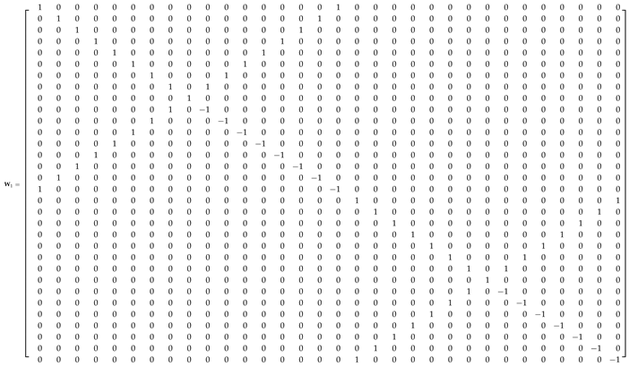
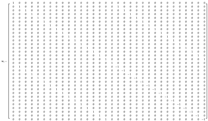
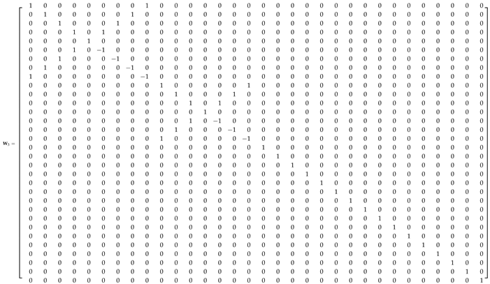
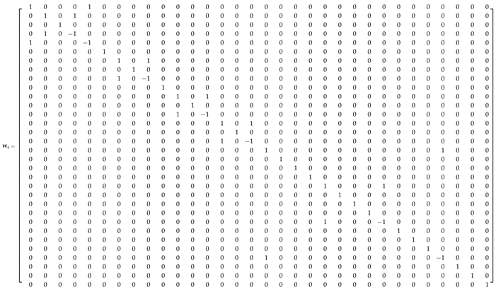
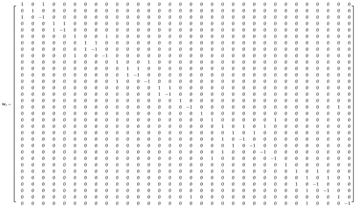
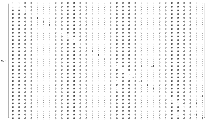
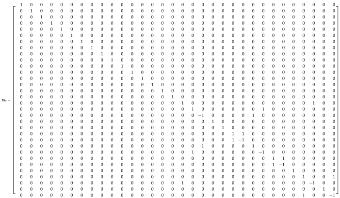
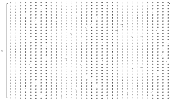
where W i , i = 1 , 2 , , 8 , are sparse, low-complexity matrices. In the Appendix A, we provide the explicit definition of matrices W i , i = 1 , 2 , , 8 .
For comparison, Table 1 lists the arithmetic operation count for the exact 32-point DFT computed according to its definition and to the radix-2 Cooley-Tukey FFT. For this operation counting, we assume that (i) the input signal is purely real-valued; (ii) trivial multiplications by 0, ± 1 , or ± j are not counted; and (iii) a multiplication between a real number and a complex number is performed as two real multiplications—not a complex multiplication [98]. Due to (i) and (iii), the 704 non-trivial multiplicands of F ^ 32 are equivalent to 1408 real multiplications. The evaluation of the number of additions considered the sum of the number of real- and imaginary-part additions. It is also provided the arithmetic complexity for the discussed 32-point ADFT by its definition and by means of its fast algorithm (factorization). The complexity analysis of the radix-2 Cooley-Tukey FFT is detailed in [98].
Table 2 shows the arithmetic complexity for each individual matrix term of the F ^ 32 factorization. The matrix W 8 does not present arithmetic costs because it consists of only sign-changing and data-swapping (real- and imaginary-part interchanging) operations. The data interchange is a consequence of the multiplication by j (a rotation by π / 2 ).

3. System Overview

3.1. Proposed Architecture

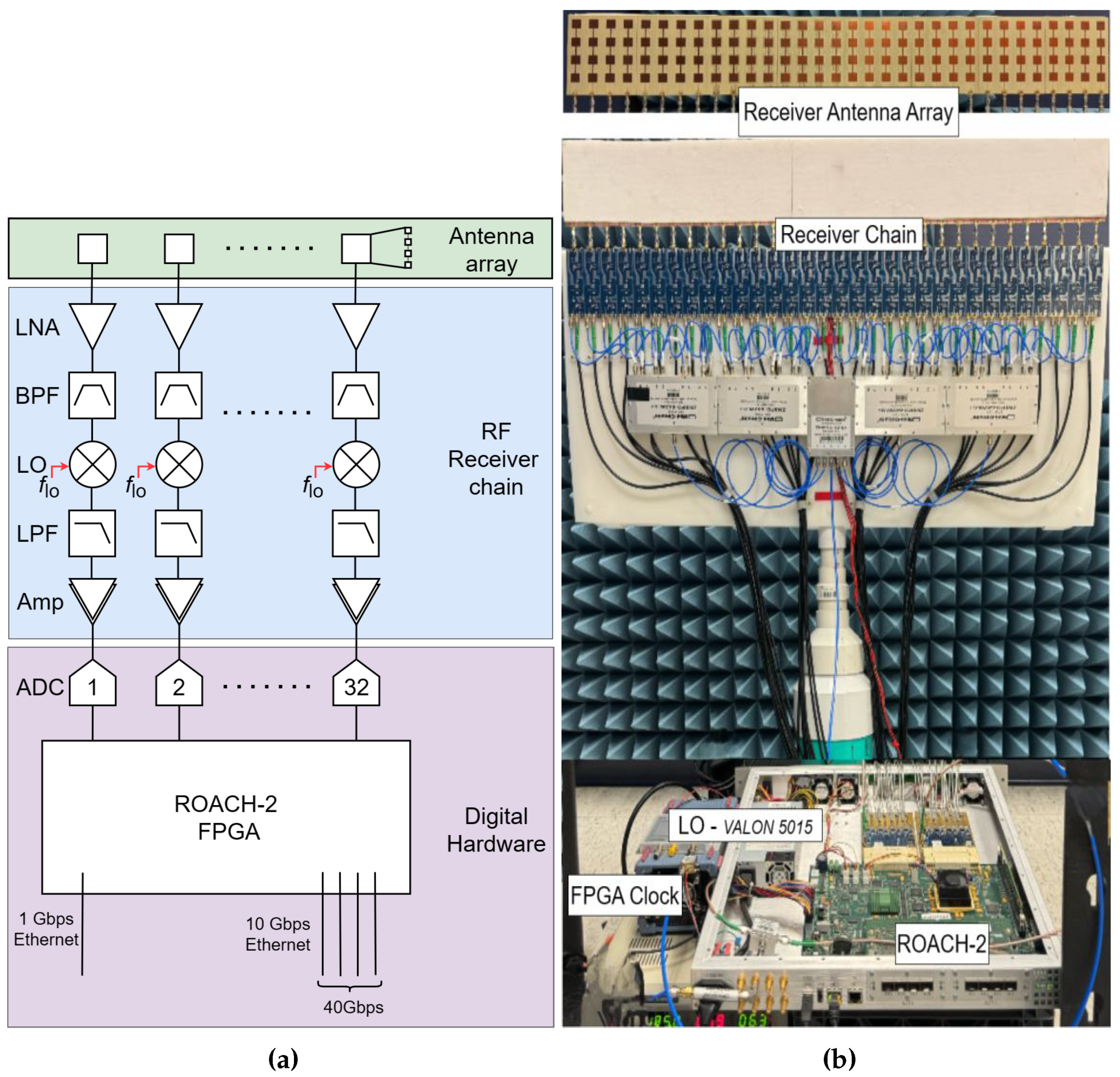
To experimentally validate and measure the beams generated by the proposed ADFT algorithms, a 5.7 GHz RF system with a digital processing back-end was meticulously designed and implemented. Figure 2(a) shows the overall architecture of the system based on a 32-element antenna array, encompassing key subsystems such as the antenna array itself, the RF receiver chain, and the digital hardware unit. Figure 2(b) shows the experimental setup of the proposed architecture. In addition to the digital cores responsible for executing the spatial DFT of the sampled signals, supplementary circuitry was developed within the FPGA. This additional circuitry facilitates real-time data manipulation and beam measurements across different angles, enhancing the flexibility and capability of the system.
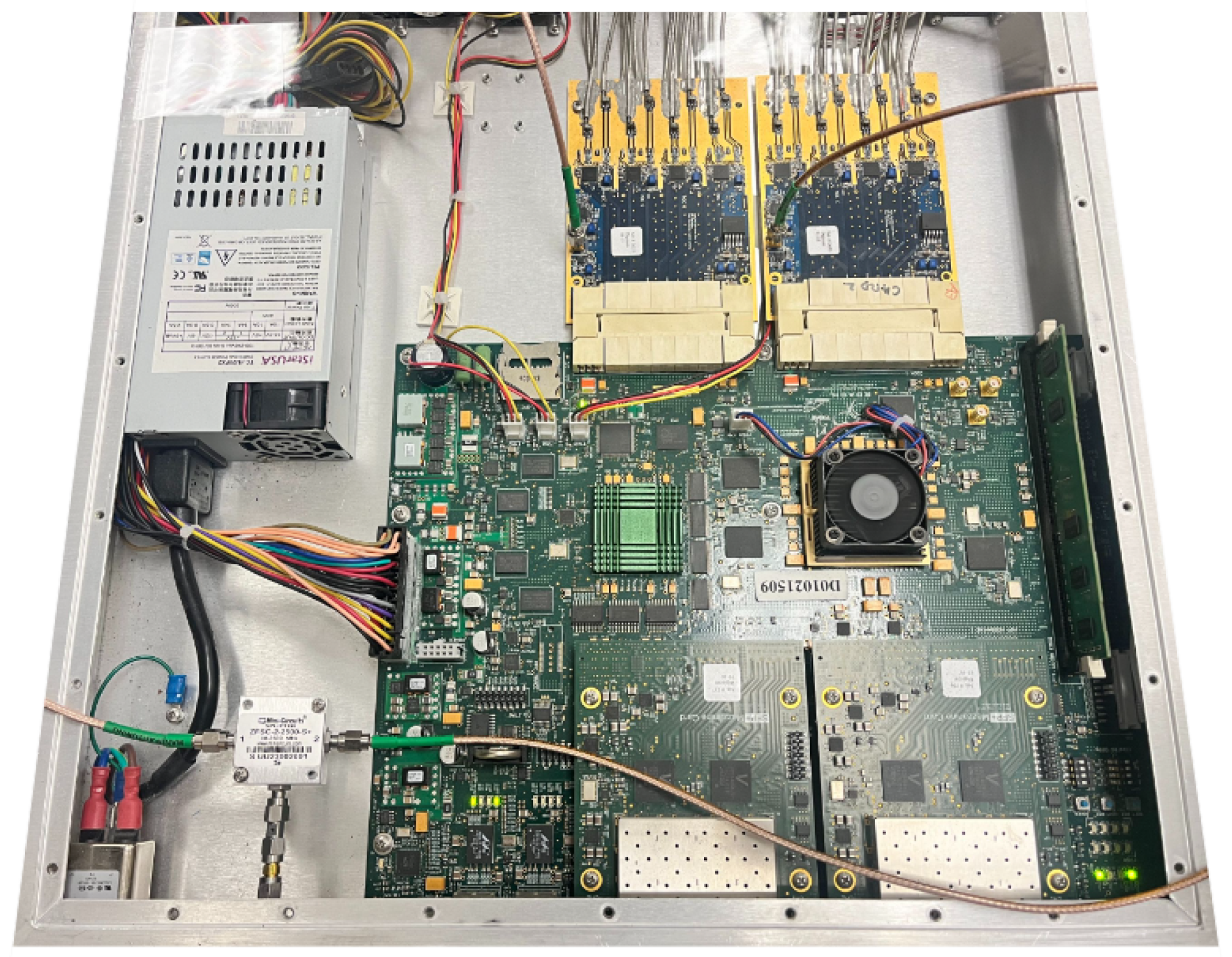
The re-configurable open architecture computing hardware (ROACH-2) based digital signal processing (DSP) platform is shown in Figure 3 which plays a crucial role by serving as an intermediary layer, enabling communication between the FPGA hardware (specifically its memory) and the onboard computer. The ROACH-2 board interfaces with the main host Linux server via a 1 Gbps Ethernet connection. A Python routine running on the host server is programmed to interact with the ROACH-2 platform, performing control functions and retrieving data from the FPGA memory while iteratively scanning through different angles. This unique system architecture not only ensures precise beam measurements but also enhances the overall efficiency and automation of the experimental providing a robust platform for validating advanced beamforming algorithms.

3.2. Analog Front-Ends

The RF front end of the receive-mode beamformer is constructed using a 32-element Uniform Linear Array (ULA) operating at 5.7 GHz, paired with 32 direct conversion RF receiver chains on printed circuit boards (PCBs). The array elements are spaced at 0 . 6 λ , which equates to approximately 32 mm at 5.7 GHz. Each antenna element is designed as a vertical subarray consisting of 4 × 1 patch antennas, facilitating passive beamforming in the vertical plane. This analog beamforming operates independently of the spatial FFT-based beamforming algorithms discussed in this work.
The outputs from the antenna elements are directly connected to 32 heterodyne receivers. These receivers utilize a centralized local oscillator (LO) system, which includes a low-phase-noise oscillator linked to a 32-output power divider network. Each receiver’s initial stage features a low-noise amplifier (LNA) that delivers 16 dB gain at 5.8 GHz with a noise figure of 2.4 dB. Following amplification, the signals are filtered through a bandpass filter spanning 4.7–6 GHz to eliminate out-of-band noise and interference. The filtered signals are then mixed and passed through low-pass filters to produce downconverted low intermediate frequency (IF) inputs.
Subsequently, these 32 low-IF signals are amplified by approximately 30 dB and digitized using two ADC16x250-8 analog-to-digital converter (ADC) cards. Each ADC card supports 16 single-ended input channels, provides 8-bit resolution, and operates at sampling rates up to 250 M sample / s per channel. This setup ensures high-fidelity digitization of the received signals for further processing [96].

3.3. ADFT Cores and Digital ADFT Spectral Estimation

The discussed 32-point ADFT was implemented by utilizing Xilinx tools. The sparse matrices from the factorization shown in (5) were structured as parallel input-output blocks to optimize performance [96,97]. Verification of these blocks was conducted through MATLAB Simulink, ensuring the reliability of the design before hardware deployment. Subsequently, the verified ADFT design was mapped onto the Xilinx Virtex-6 sx475T FPGA.
To integrate the ADFT core into the ROACH-2 FPGA platform, we utilized two libraries from the Collaboration for Astronomy Signal Processing and Electronics Research (CASPER) community [100,101]. This integration enabled the system to generate 32 simultaneous RF beams in parallel. Each beam corresponds to a discrete direction, calculated using the function θ k = arcsin ( k / 32 ) , k ranges from 16 to 15. The successful implementation of the ADFT on the ROACH-2 FPGA not only validated the algorithm effectiveness but also demonstrated the practical application of advanced digital hardware design techniques. This work highlights the potential of ADFT in various applications requiring efficient RF beamforming.
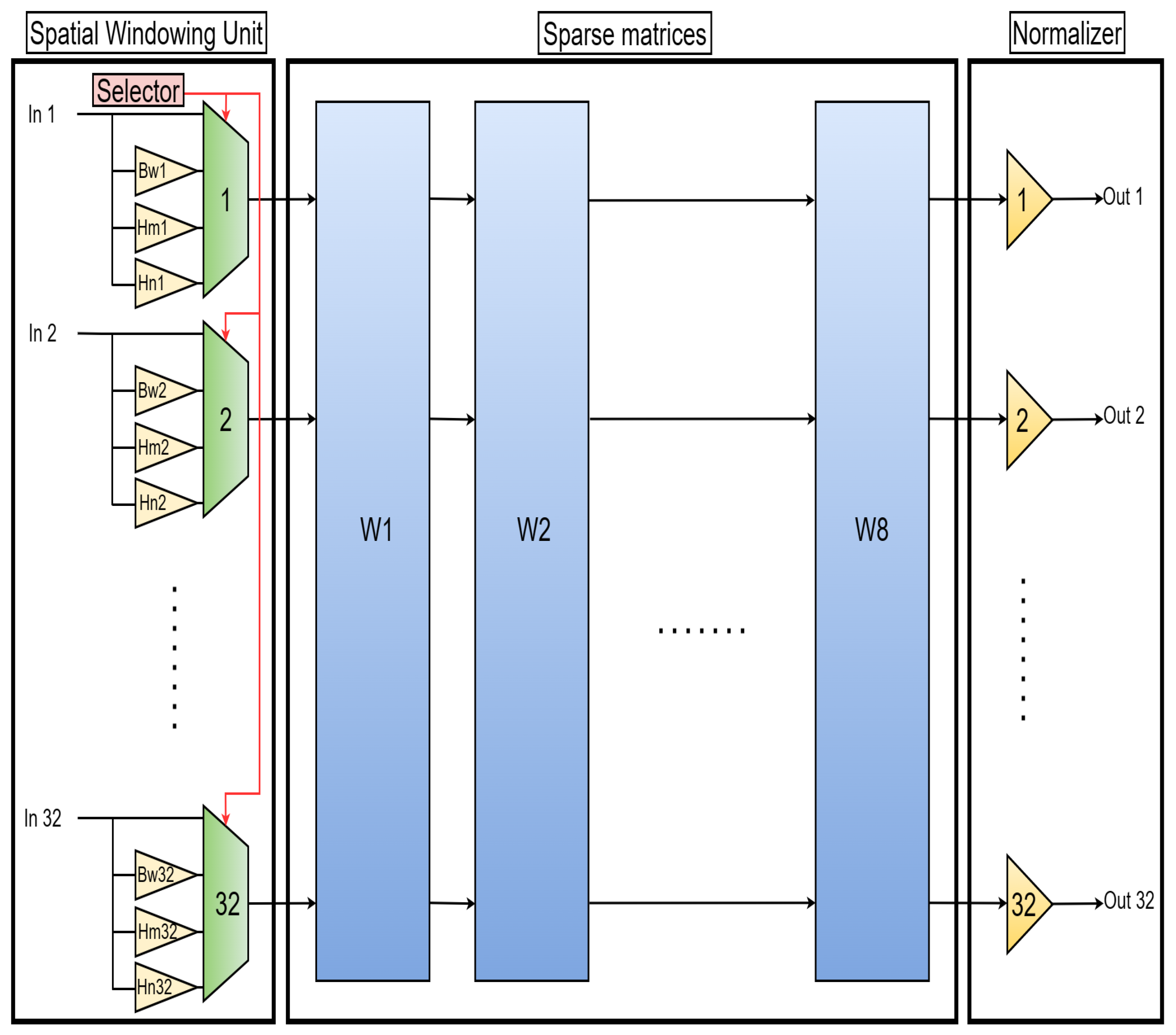
We implemented a spatial windowing technique to address the issue of high side lobes in the ADFT, where the worst-case side lobe was observed to be 1.5 dB higher than that of the (exact) DFT. Four configurations were tested: three windowing functions (Butterworth, Hamming, and Hanning) and a baseline with no windowing [102]. The selection among these windowing functions was managed using a multiplexer equipped with a control selector pin.
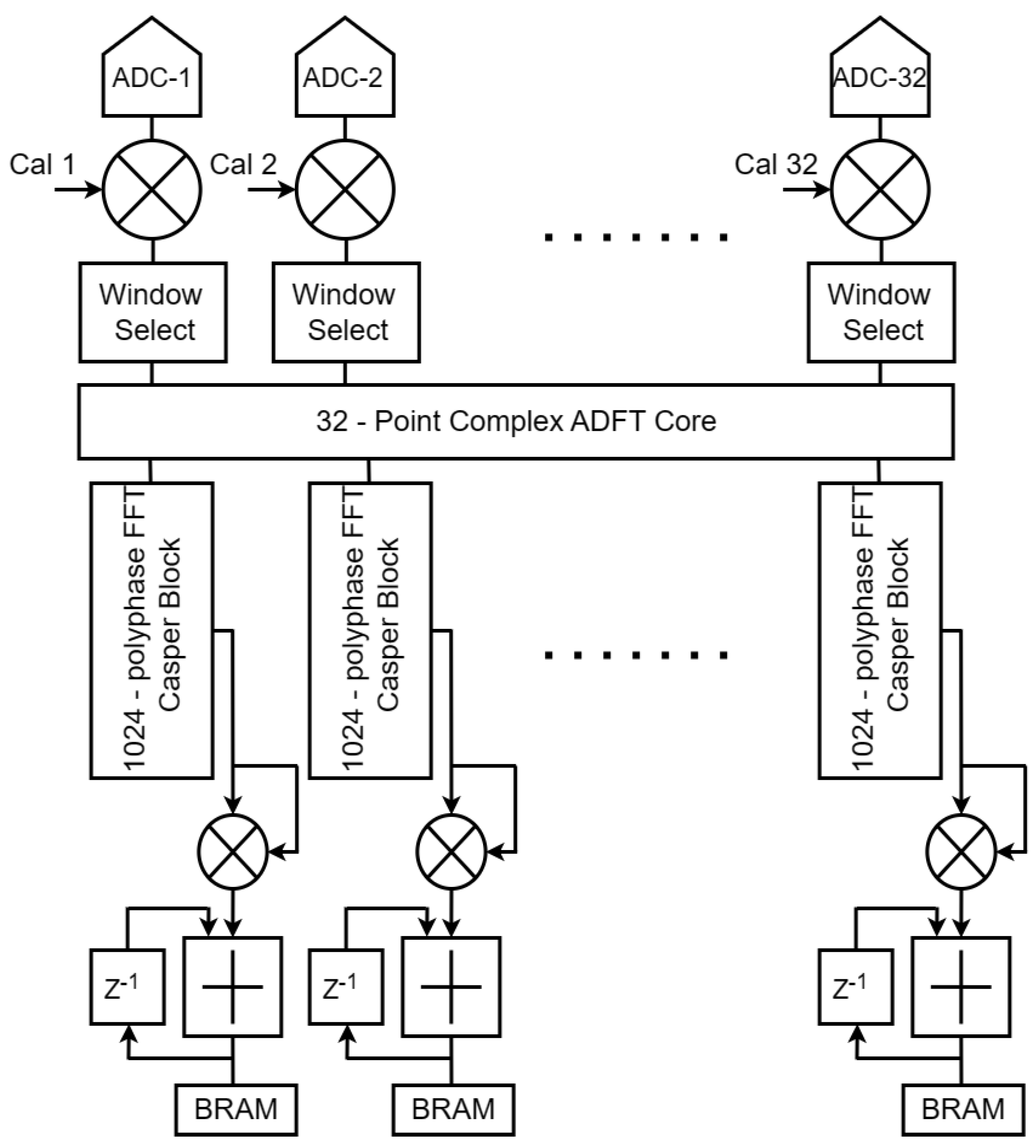
Figure 4 shows the spatial windowing unit coupled with the ADFT sparse matrices. In mathematical terms, the windowing is introduced as diagonal matrix. The ADFT-based spectral estimation can be described by combining the windowing diagonal matrix ( D windowing ), the low-complexity ADFT core ( F ^ 32 ), and a power-normalizing diagonal matrix ( D normalizer ). The mathematical representation of the proposed approximate spectrum estimation is given by:
ADFT estimator = D normalizer · F ^ 32 · D windowing .
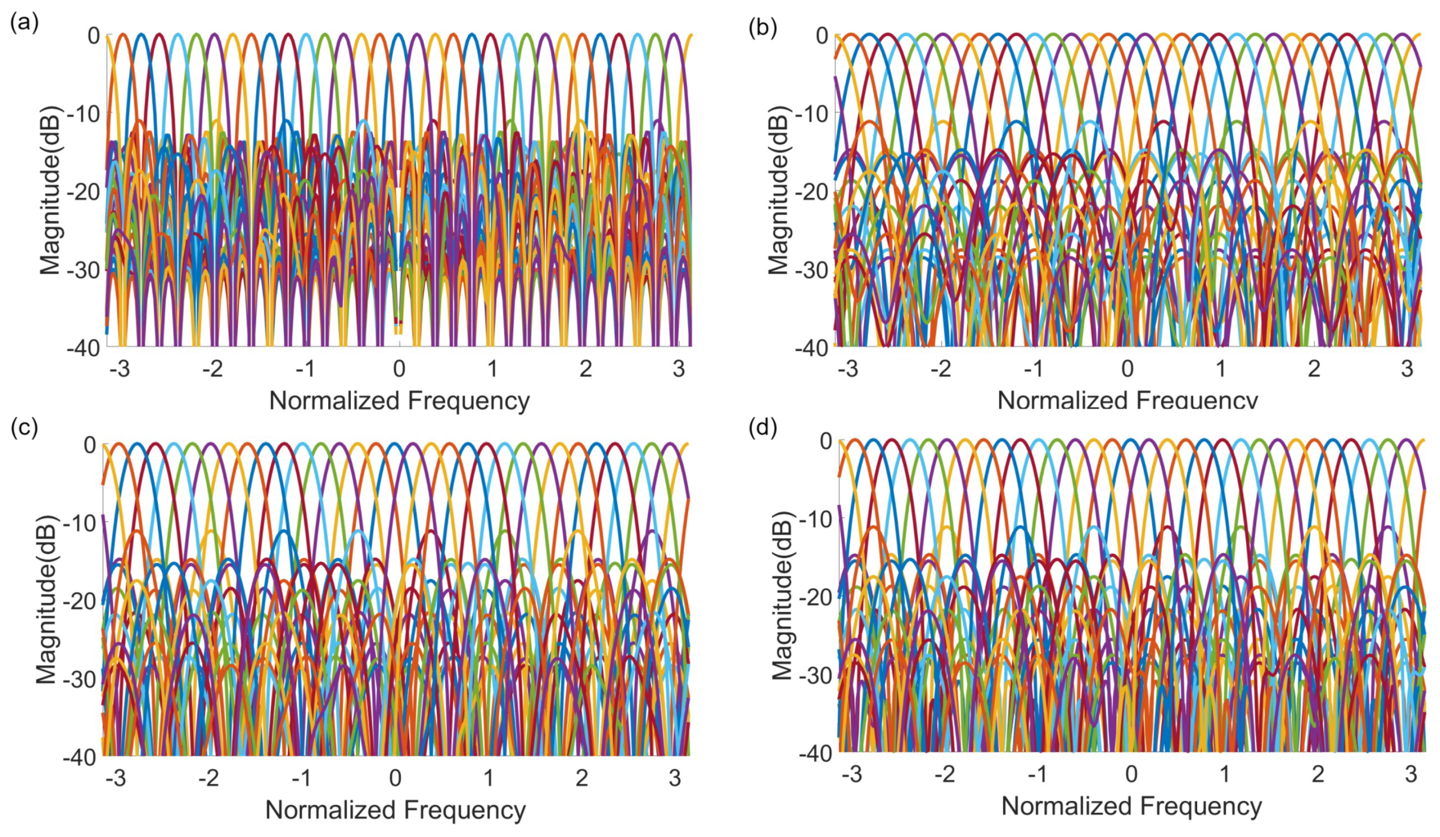
Figure 5 illustrates the ADFT response and its modifications under the windowing techniques. It is noteworthy that the introduction of windowing functions resulted in wider main lobes, which is a compromise made to suppress the side lobes. This trade-off between main lobe width and side lobe suppression is a consideration in the application of spatial windowing techniques. However, implementing spatial windowing increases the hardware complexity due to the multiplexers introduced by the windowing unit. Therefore, user must select the appropriate configuration based on their specific requirements and constraints.

3.4. Digital FFT Spectrometers

The system described involves the implementation of a spatial FFT that generates 32 parallel outputs, each corresponding to a distinct spatial RF beam. Subsequent to this spatial FFT, a temporal FFT spectrometer is applied to each of these 32 spatial RF beams, achieving channelization in the temporal frequency domain. Each temporal FFT is computed with 1024 points, necessitating the use of 32 parallel FFT cores. This parallel processing is facilitated by leveraging real-sampled biplex FFT blocks available in the Xilinx Virtex-6 SX475T FPGA.
The real-sampled biplex FFT blocks exploit the Hermitian conjugation method, enabling the computation of the real-sampled FFT. This technique utilizes a complex FFT core to simultaneously transform two real-valued data streams. As a result, the FFT operation produces all frequencies, both positive and negative, with negative frequencies being the mirror images of their positive counterparts[100].
The temporal FFT outputs for each beam yield 1024 complex values corresponding to 1024 discrete frequency bins. The power spectral density (PSD) is estimated by squaring the magnitude of each frequency bin. This estimate is derived by averaging across 1024 temporal FFT evaluations, resulting in a new PSD measurement every 1 million clock cycles. A Block random access memory (BRAM) vector accumulator block collects the PSD values and transfers them to the software process supported by the CASPER design flow. Figure 6 shows the overall ADFT and temporal FFT flow, including energy integration and BRAM registers. The casperfpga Python library is used to interact with CASPER hardware, extracting values from the shared BRAM.
The FPGA operates with a clock frequency set to 200 MHz. Given this configuration, the system frequency resolution for each beam is determined to be Δ F = 100 / 1024 MHz, which is approximately 100 kHz. The Nyquist bandwidth of the system is thus 100 MHz. This configuration ensures precise channelization and high-resolution frequency analysis for each of the 32 spatial RF beams.

3.5. Digital High-Speed Connectivity

The ROACH-2 boards are equipped with four SFP+ ports on a single 10 GbE mezzanine card, where the Ethernet interface is driven by an on-board 156.25 MHz crystal oscillator. This clock frequency is internally multiplied by a factor of 66 within the FPGA, resulting in an effective wire speed of 10.3125 Gbps.
The CASPER 10 Simulink core facilitates the transmission and reception of UDP packets over IPv4, encapsulated within Ethernet frames. Each Ethernet frame incurs an overhead of 38 bytes for the frame header, 20 bytes for the IPv4 header, and 16 bytes for the UDP header, totaling at least 74 bytes of overhead per packet. To align with 64-bit boundaries, some headers may also include zero-padding, further impacting the effective throughput. The maximum payload size for the CASPER 10 core is 8192 bytes, implemented in BRAM, with an additional 512 bytes available in distributed RAM for application-specific headers [100].

4. Experimental Results

4.1. Calibration

Calibration of the RF array system is essential for optimal beamforming performance and was carried out in two distinct phases. Initially, the calibration focused on the ADCs, utilizing open-source routines previously developed by CASPER group members for this hardware. The second phase addressed digital correction of mismatches in the microwave front end. Relative gain and phase mismatches of the IF outputs for each chain were determined in relation to a reference chain using a 5.71 GHz reference carrier input. The relative gain differences were compensated using digital multipliers and gain scale factors were calculated by measuring average power values of each ADC output. Ideally, for phase difference compensation, fractional delay filters are required, as the RF chains could have smaller delays than sampling period value. As an interim solution, integer delay filters were designed and implemented in the hardware to mitigate phase differences.

4.2. Beam Measurements

Power patterns were obtained by transmitting a continuous-wave (CW) signal at f RF = 5 . 71 GHz. The LO signal frequency f LO determines the IF as f RF f LO . For the measurements in this study, f LO was set to 5.7 GHz, resulting in an IF of 10 MHz, with the downconverted outputs digitized at f CLK = 200 MHz.
Digital integrator at each ADFT bin output were used to compute the received energy over a fixed duration. The geometry of the measurement setup significantly influences the measured array factor of the beams. Ideally, the transmitter and receiver should be sufficiently far apart so that the waves incident on the receiver array can be approximated as plane waves. According to standard guidelines [103], the separation between the transmitter and receiver should exceed 20 m at 5.7 GHz to ensure that the receiver aperture is in the far-field. The beams were measured on an open parking deck with a transmitter-receiver separation of approximately 20 m .
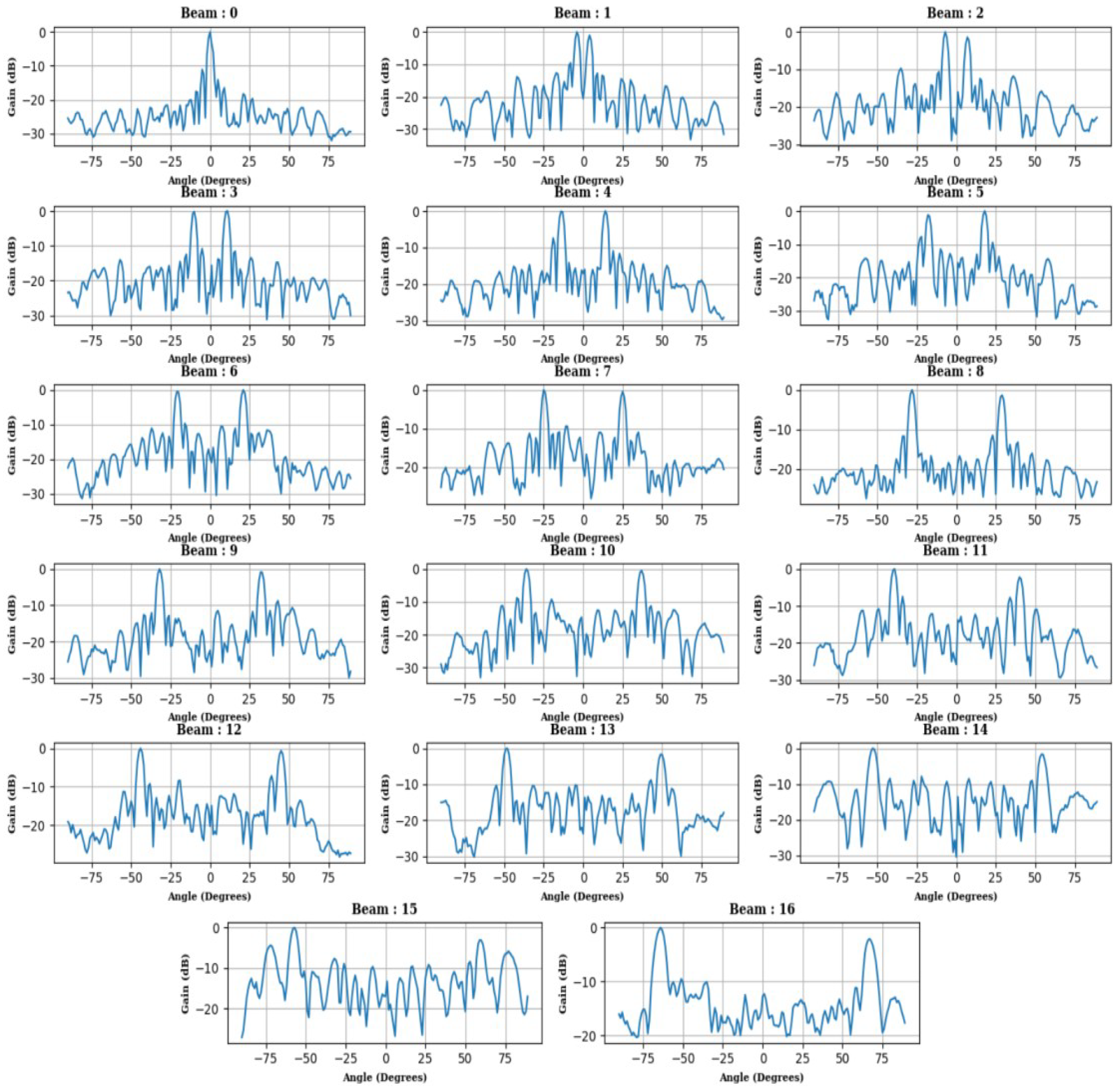
Figure 7 illustrates the measured array factor patterns for beams 0 to 16. Due to the input of real-valued IF signals into the ADFT, the resulting beam patterns exhibit symmetry, producing mirror images for the remaining bins. Additionally, the presence of two mirror peaks is observed within bins 0 to 16. The measured beams conform closely to the expected patterns, maintaining a separation of more than 10 dB from the other beam.
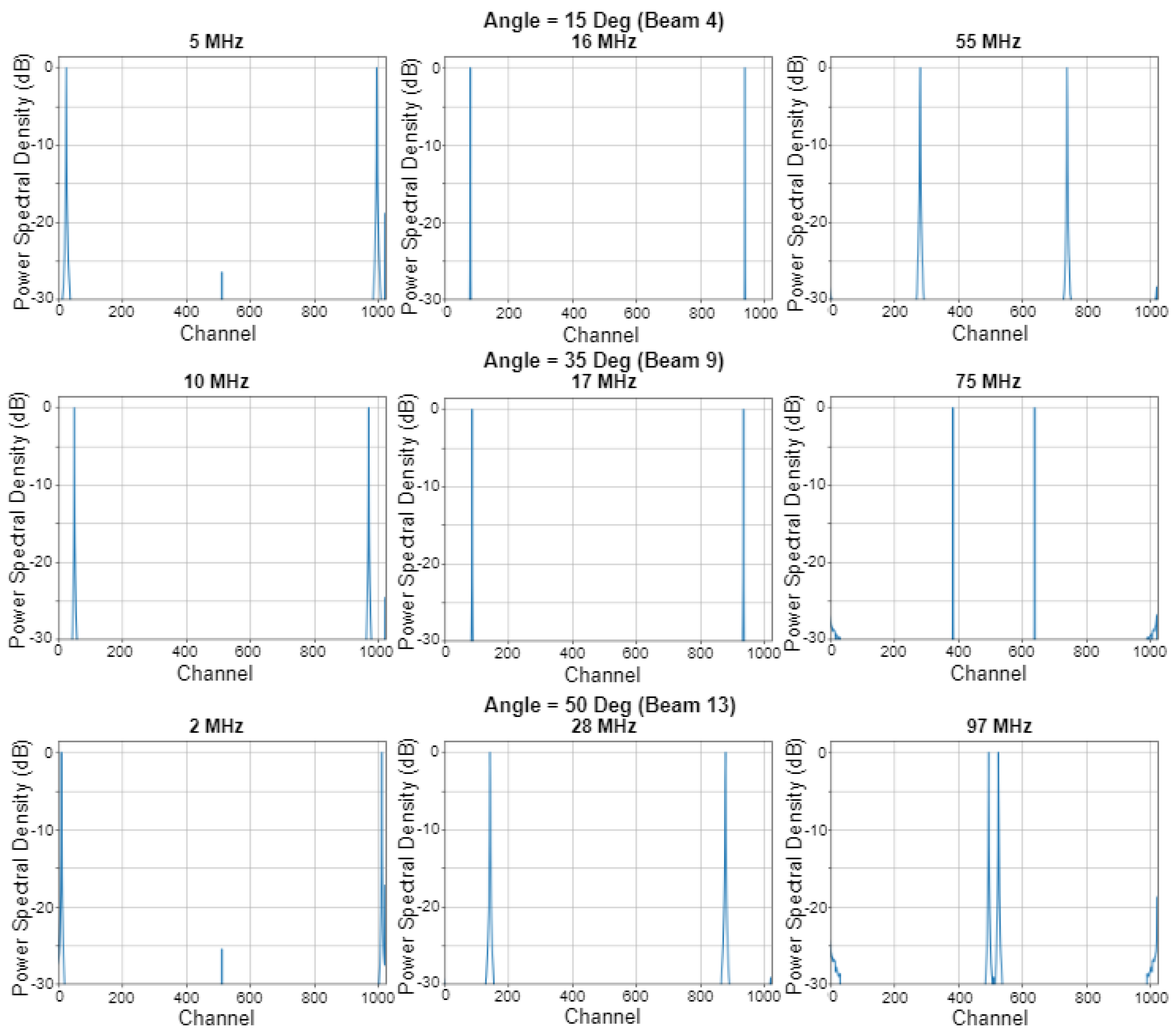
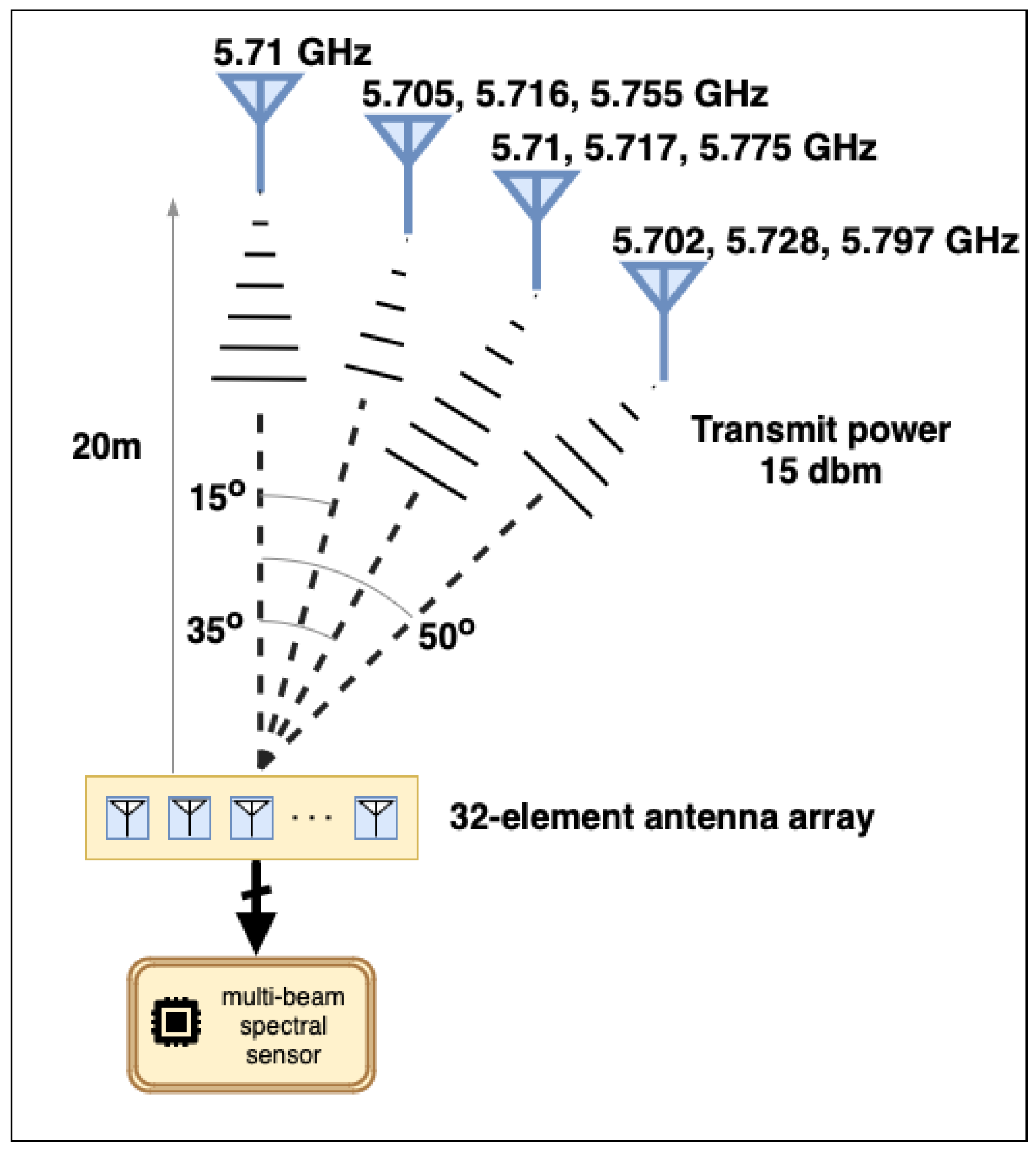
Figure 8 depicts the measured temporal PSD distribution of respective beams at multiple frequencies when the signal source is positioned on broadside angle of 15°, 35°, and 50°. The corresponding experimental setup with relative source locations and RF frequencies being emitted for testing purposes is shown in Figure 9.

5. Discussion

This paper presents a low-complexity digital beamforming architecture designed to generate 32 simultaneous RF beams using a 32-point DFT approximation, effectively eliminating multiplication operations. We validated the proposed method on a fully operational 32-element digital 1-D receive array operating at 5.7 GHz. The 1-D array employs 32 parallel ADCs for sampling the antenna outputs and uses an ADFT implemented on a Xilinx FPGA to compute 32 RF beams in real time. Additionally, the paper discusses the enhancement of our existing 32-channel 5.7 GHz spectrum sensing system through the implementation of 32 parallel 1024-bin temporal FFTs on a ROACH-2 hardware platform. This experimental verification with real-time measurements across a band of frequencies and angles of incidence demonstrates the capability of the architecture to sense information from multiple directions with a frequency resolution of 100 and directional resolution of about 6°.

Author Contributions

Conceptualization and system design by Madanayake. Theory and design of ADFT and fast algorithm by Cintra. Multidimensional signal processing review by Edussooriya. Review of radio astronomy interference issues by Gunaratne. Digital implementation of ADFT core by Lawrance. Experimental setup, digital design on CASPER tools, calibration and real-time experimentation by Sivasankar and Kumarasiri.

Funding

This work was supported in part by NSF (FuSE, SWIFT, ICORPS, SpectrumX), NTIA and CNPq (Brazil).

Data Availability Statement

All original contributions from this study are documented within the article. For further details, please contact the corresponding authors.

Conflicts of Interest

The authors declare no conflict of interest.

Abbreviations

The following abbreviations are used in this manuscript:
ADC Analog to digital converter
ADFT Approximate discrete Fourier transform
AI Artificial intelligent
ALMA Atacama large millimeter array
BRAM Block random access memory
CASPER Collaboration for astronomy signal processing and electronics research
CSI Channel state information
CW Continuous wave
DFT Discrete Fourier transform
DL Deep learning
DSA Dynamic spectrum access
DSP Digital signal processing
FCC Federal communication commission
FFT Fast Fourier transform
FPGA Field programmable gate array
GNSS Global navigation satellite system
IF Intermediate frequency
IOT Internet of things
ISI Inter-symbol interference
ITU International telecommunication union
LNA Low noise amplifier
LO Local oscillator
ML Machine learning
ngVLA Next generation very large array
NSF National science foundation
OET Office of engineering and technology
PCB Printed circuit board
PSD Power spectral density
PU Primary user
RF Radio frequency
RFI Radio frequency interference
RL Reinforcement learning
ROACH Reconfigurable open architecture computing hardware
SDR Software defined radio
SFP Small form-factor pluggable
SNR Signal to noise ratio
SU Secondary user
ULA Uniform linear array
WSU Wideband sensitivity upgrade

Appendix A

Appendix A.1. 32-Point ADFT Fast Algorithm
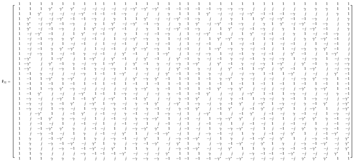
The fast algorithm for the discussed 32-point approximate DFT F ^ 32 consists of a factorization in low-complexity, sparse matrices, as shown in (5). The approximate matrix and its factorization terms are explicitly given below:
Preprints 111158 i001
where γ = 1 + j and * denotes complex conjugation,
Preprints 111158 i002
Preprints 111158 i003
Preprints 111158 i004
Preprints 111158 i005
Preprints 111158 i006
Preprints 111158 i007
Preprints 111158 i008
and
Preprints 111158 i009

References

  1. Tolkien, J. The Hobbit & The Lord of the Rings; Houghton Mifflin Harcourt, 1954.
  2. Kang, S.; Mezzavilla, M.; Rangan, S.; Madanayake, A.; Venkatakrishnan, S.B.; Hellbourg, G.; Ghosh, M.; Rahmani, H.; Dhananjay, A. Cellular Wireless Networks in the Upper Mid-Band. IEEE Open Journal of the Communications Society 2024, pp. 1–1. [CrossRef]
  3. The White House. NATIONAL SPECTRUM STRATEGY, 2023.
  4. Restuccia, F.; Melodia, T. Deep Learning at the Physical Layer: System Challenges and Applications to 5G and Beyond. IEEE Communications Magazine 2020, 58, 58–64. [CrossRef]
  5. Triaridis, K.; Doumanidis, C.; Chatzidiamantis, N.D.; Karagiannidis, G.K. MM-Net: A Multi-Modal approach towards Automatic Modulation Classification. IEEE Communications Letters 2023, pp. 1–1. [CrossRef]
  6. Baldesi, L.; Restuccia, F.; Melodia, T. ChARM: NextG Spectrum Sharing Through Data-Driven Real-Time O-RAN Dynamic Control. In Proceedings of the Proceedings of IEEE International Conference on Computer Communications (INFOCOM). IEEE, 2022, pp. 240–249.
  7. Zhang, L.; Xiao, M.; Wu, G.; Alam, M.; Liang, Y.C.; Li, S. A Survey of Advanced Techniques for Spectrum Sharing in 5G Networks. IEEE Wireless Communications 2017, 24, 44–51. [CrossRef]
  8. Hu, F.; Chen, B.; Zhu, K. Full Spectrum Sharing in Cognitive Radio Networks Toward 5G: A Survey. IEEE Access 2018, 6, 15754–15776. [CrossRef]
  9. Shokri-Ghadikolaei, H.; Boccardi, F.; Fischione, C.; Fodor, G.; Zorzi, M. Spectrum Sharing in mmWave Cellular Networks via Cell Association, Coordination, and Beamforming. IEEE Journal on Selected Areas in Communications 2016, 34, 2902–2917. [CrossRef]
  10. Lv, L.; Chen, J.; Ni, Q.; Ding, Z.; Jiang, H. Cognitive Non-Orthogonal Multiple Access with Cooperative Relaying: A New Wireless Frontier for 5G Spectrum Sharing. IEEE Communications Magazine 2018, 56, 188–195. [CrossRef]
  11. Agarwal, S.; De, S. eDSA: Energy-efficient Dynamic Spectrum Access Protocols for Cognitive Radio Networks. IEEE Transactions on Mobile Computing 2016, 15, 3057–3071. [CrossRef]
  12. Chiwewe, T.M.; Hancke, G.P. Fast Convergence Cooperative Dynamic Spectrum Access for Cognitive Radio Networks. IEEE Transactions on Industrial Informatics 2017. [CrossRef]
  13. Chang, H.H.; Song, H.; Yi, Y.; Zhang, J.; He, H.; Liu, L. Distributive Dynamic Spectrum Access Through Deep Reinforcement Learning: A Reservoir Computing-based Approach. IEEE Internet of Things Journal 2018, 6, 1938–1948. [CrossRef]
  14. Nguyen, H.Q.; Nguyen, B.T.; Dong, T.Q.; Ngo, D.T.; Nguyen, T.A. Deep Q-Learning with Multiband Sensing for Dynamic Spectrum Access. In Proceedings of the IEEE International Symposium on Dynamic Spectrum Access Networks (DySPAN), Oct 2018, pp. 1–5. [CrossRef]
  15. Naparstek, O.; Cohen, K. Deep Multi-user Reinforcement Learning for Distributed Dynamic Spectrum Access. IEEE Transactions on Wireless Communications 2019, 18, 310–323. [CrossRef]
  16. Wang, S.; Liu, H.; Gomes, P.H.; Krishnamachari, B. Deep Reinforcement Learning for Dynamic Multichannel Access in Wireless Networks. IEEE Transactions on Cognitive Communications and Networking 2018, 4, 257–265. [CrossRef]
  17. Yu, Y.; Wang, T.; Liew, S.C. Deep-Reinforcement Learning Multiple Access for Heterogeneous Wireless Networks. IEEE Journal on Selected Areas in Communications 2019, 37, 1277–1290. [CrossRef]
  18. Reston,VA. Ligado Networks Sues U.S. Government for Unlawful and Uncompensated Taking of Ligado’s Exclusive FCC-Licensed Spectrum, 2023.
  19. Barden, S.; Dewdney, P.; Friesen, R.; Murowinski, R.; Savanandam, S. ATD Strategic R&D Review Report - Signal Processing Portfolio. Herzberg Astronomy and Astrophysics Research Centre- National Research Council Canada, BC, Canada March 2022.
  20. FCC Spectrum Policy Task Force. Report of the spectrum efficiency working group, Nov. 2002. Accessed on May 28, 2024.
  21. Mitola, J.; Maguire, G. Cognitive radio: making software radios more personal. IEEE Personal Communications 1999, 6, 13–18. [CrossRef]
  22. Haykin, S. Cognitive radio: brain-empowered wireless communications. IEEE Journal on Selected Areas in Communications 2005, 23, 201–220. [CrossRef]
  23. Liang, Y.C.; Chen, K.C.; Li, G.Y.; Mahonen, P. Cognitive radio networking and communications: an overview. IEEE Transactions on Vehicular Technology 2011, 60, 3386–3407. [CrossRef]
  24. Wang, B.; Liu, K.R. Advances in cognitive radio networks: A survey. IEEE Journal of Selected Topics in Signal Processing 2011, 5, 5–23. [CrossRef]
  25. Zhao, Q.; Sadler, B.M. A Survey of Dynamic Spectrum Access. IEEE Signal Processing Magazine 2007, 24, 79–89. [CrossRef]
  26. Ji, Z.; Liu, K.R. Dynamic Spectrum Sharing: A Game Theoretical Overview. IEEE Communications Magazine 2007, 45, 88–94. [CrossRef]
  27. Bhattarai, S.; Park, J.M.J.; Gao, B.; Bian, K.; Lehr, W. An Overview of Dynamic Spectrum Sharing: Ongoing Initiatives, Challenges, and a Roadmap for Future Research. IEEE Transactions on Cognitive Communications and Networking 2016, 2, 110–128. [CrossRef]
  28. Zeng, Y.; Liang, Y.C.; Zhang, R. Blindly Combined Energy Detection for Spectrum Sensing in Cognitive Radio. IEEE Signal Processing Letters 2008, 15, 649–652. [CrossRef]
  29. Ling, X.; Wu, B.; Wen, H.; Ho, P.H.; Bao, Z.; Pan, L. Adaptive Threshold Control for Energy Detection Based Spectrum Sensing in Cognitive Radios. IEEE Wireless Communications Letters 2012, 1, 448–451. [CrossRef]
  30. Ranjan, A.; Anurag.; Singh, B. Design and analysis of spectrum sensing in cognitive radio based on energy detection. In Proceedings of the International Conference on Signal and Information Processing, 2016, pp. 1–5.
  31. Arjoune, Y.; Mrabet, Z.E.; Ghazi, H.E.; Tamtaoui, A. Spectrum sensing: Enhanced energy detection technique based on noise measurement. In Proceedings of the IEEE Annual Computing and Communication Workshop and Conference, 2018, pp. 828–834.
  32. Jiang, C.; Li, Y.; Bai, W.; Yang, Y.; Hu, J. Statistical matched filter based robust spectrum sensing in noise uncertainty environment. In Proceedings of the International Conference on Communication Technology, 2012, pp. 1209–1213.
  33. Zhang, X.; Chai, R.; Gao, F. Matched filter based spectrum sensing and power level detection for cognitive radio network. In Proceedings of the IEEE Global Conference on Signal and Information Processing, 2014, pp. 1267–1270.
  34. Lv, Q.; Gao, F. Matched filter based spectrum sensing and power level recognition with multiple antennas. In Proceedings of the IEEE China Summit and International Conference on Signal and Information Processing, 2015, pp. 305–309.
  35. Ilyas, I.; Paul, S.; Rahman, A.; Kundu, R.K. Comparative evaluation of cyclostationary detection based cognitive spectrum sensing. In Proceedings of the IEEE Annual Ubiquitous Computing, Electronics & Mobile Communication Conference, 2016, pp. 1–7.
  36. Cohen, D.; Eldar, Y.C. Compressed cyclostationary detection for Cognitive Radio. In Proceedings of the 2017 IEEE International Conference on Acoustics, Speech and Signal Processing (ICASSP), 2017, pp. 3509–3513.
  37. Zeng, Y.; Liang, Y.C. Spectrum-Sensing Algorithms for Cognitive Radio Based on Statistical Covariances. IEEE Transactions on Vehicular Technology 2009, 58, 1804–1815. [CrossRef]
  38. Zeng, Y.; Liang, Y.C. Eigenvalue-based spectrum sensing algorithms for cognitive radio. IEEE Transactions on Communications 2009, 57, 1784–1793. [CrossRef]
  39. Zayen, B.; Hayar, A.; Kansanen, K. Blind Spectrum Sensing for Cognitive Radio Based on Signal Space Dimension Estimation. In Proceedings of the 2009 IEEE International Conference on Communications, 2009, pp. 1–5.
  40. Farhang-Boroujeny, B. Filter Bank Spectrum Sensing for Cognitive Radios. IEEE Transactions on Signal Processing 2008, 56, 1801–1811. [CrossRef]
  41. Quan, Z.; Cui, S.; Sayed, A.H.; Poor, H.V. Optimal Multiband Joint Detection for Spectrum Sensing in Cognitive Radio Networks. IEEE Transactions on Signal Processing 2009, 57, 1128–1140. [CrossRef]
  42. Raghu, I.; Chowdary, S.S.; Elias, E. Efficient spectrum sensing for Cognitive Radio using Cosine Modulated Filter Banks. In Proceedings of the IEEE Region 10 Conference, 2016, pp. 2086–2089.
  43. Kumar, A.; Saha, S.; Bhattacharya, R. Improved wavelet transform based edge detection for wide band spectrum sensing in Cognitive Radio. In Proceedings of the USNC-URSI Radio Science Meeting, 2016, pp. 21–22.
  44. Polo, Y.L.; Wang, Y.; Pandharipande, A.; Leus, G. Compressive wide-band spectrum sensing. In Proceedings of the IEEE International Conference on Acoustics, Speech and Signal Processing, 2009, pp. 2337–2340.
  45. Arjoune, Y.; Kaabouch, N. Wideband Spectrum Sensing: A Bayesian Compressive Sensing Approach. Sensors 2018, 18, 1–15. [CrossRef] [PubMed]
  46. Li, Z.; Chang, B.; Wang, S.; Liu, A.; Zeng, F.; Luo, G. Dynamic Compressive Wide-Band Spectrum Sensing Based on Channel Energy Reconstruction in Cognitive Internet of Things. IEEE Transactions on Industrial Informatics 2018, 14, 2598–2607. [CrossRef]
  47. Yang, L.; Fang, J.; Duan, H.; Li, H. Fast Compressed Power Spectrum Estimation: Toward a Practical Solution for Wideband Spectrum Sensing. IEEE Transactions on Wireless Communications 2020, 19, 520–532. [CrossRef]
  48. Ding, G.; Wu, Q.; Yao, Y.D.; Wang, J.; Chen, Y. Kernel-Based Learning for Statistical Signal Processing in Cognitive Radio Networks: Theoretical Foundations, Example Applications, and Future Directions. IEEE Signal Processing Magazine 2013, 30, 126–136. [CrossRef]
  49. Thilina, K.M.; Choi, K.W.; Saquib, N.; Hossain, E. Machine Learning Techniques for Cooperative Spectrum Sensing in Cognitive Radio Networks. IEEE Journal on Selected Areas in Communications 2013, 31, 2209–2221. [CrossRef]
  50. Mikaeil, A.M.; Guo, B.; Wang, Z. Machine Learning to Data Fusion Approach for Cooperative Spectrum Sensing. In Proceedings of the International Conference on Cyber-Enabled Distributed Computing and Knowledge Discovery, 2014, pp. 429–434.
  51. Ghazizadeh, E.; Nikpour, B.; Moghadam, D.A.; Nezamabadi-pour, H. A PSO-based weighting method to enhance machine learning techniques for cooperative spectrum sensing in CR networks. In Proceedings of the Conference on Swarm Intelligence and Evolutionary Computation, 2016, pp. 113–118.
  52. Khalfi, B.; Zaid, A.; Hamdaoui, B. When machine learning meets compressive sampling for wideband spectrum sensing. In Proceedings of the International Wireless Communications and Mobile Computing Conference, 2017, pp. 1120–1125.
  53. Lee, W.; Kim, M.; Cho, D.H. Deep Cooperative Sensing: Cooperative Spectrum Sensing Based on Convolutional Neural Networks. IEEE Transactions on Vehicular Technology 2019, 68, 3005–3009. [CrossRef]
  54. Liu, C.; Wang, J.; Liu, X.; Liang, Y.C. Deep CM-CNN for Spectrum Sensing in Cognitive Radio. IEEE Journal on Selected Areas in Communications 2019, 37, 2306–2321. [CrossRef]
  55. Soni, B.; Patel, D.K.; López-Benítez, M. Long Short-Term Memory Based Spectrum Sensing Scheme for Cognitive Radio Using Primary Activity Statistics. IEEE Access 2020, 8, 97437–97451. [CrossRef]
  56. Peng, Q.; Gilman, A.; Vasconcelos, N.; Cosman, P.C.; Milstein, L.B. Robust Deep Sensing Through Transfer Learning in Cognitive Radio. IEEE Wireless Communications Letters 2020, 9, 38–41. [CrossRef]
  57. Zhang, W.; Wang, Y.; Chen, X.; Cai, Z.; Tian, Z. Spectrum Transformer: An Attention-based Wideband Spectrum Detector. IEEE Transactions on Wireless Communications 2024, pp. 1–1.
  58. Sarikhani, R.; Keynia, F. Cooperative Spectrum Sensing Meets Machine Learning: Deep Reinforcement Learning Approach. IEEE Communications Letters 2020, 24, 1459–1462. [CrossRef]
  59. Cai, P.; Zhang, Y.; Pan, C. Coordination Graph-Based Deep Reinforcement Learning for Cooperative Spectrum Sensing Under Correlated Fading. IEEE Wireless Communications Letters 2020, 9, 1778–1781. [CrossRef]
  60. Gao, A.; Du, C.; Ng, S.X.; Liang, W. A Cooperative Spectrum Sensing With Multi-Agent Reinforcement Learning Approach in Cognitive Radio Networks. IEEE Communications Letters 2021, 25, 2604–2608. [CrossRef]
  61. Ngo, Q.T.; Jayawickrama, B.A.; He, Y.; Dutkiewicz, E. Multi-Agent DRL-Based RIS-Assisted Spectrum Sensing in Cognitive Satellite–Terrestrial Networks. IEEE Wireless Communications Letters 2023, 12, 2213–2217. [CrossRef]
  62. Ali, A.; Hamouda, W. Advances on Spectrum Sensing for Cognitive Radio Networks: Theory and Applications. IEEE Communications Surveys & Tutorials 2017, 19, 1277–1304.
  63. Arjoune, Y.; Kaabouch, N. A Comprehensive Survey on Spectrum Sensing in Cognitive Radio Networks: Recent Advances, New Challenges, and Future Research Directions. Sensors 2019, 19, 1–32. [CrossRef]
  64. Zhang, Y.; Luo, Z. A Review of Research on Spectrum Sensing Based on Deep Learning. Electronics 2023, 12, 1–42. [CrossRef]
  65. Wijenayake, C.; Madanayake, A.; Kota, J.; Bruton, L. Space-Time Spectral White Spaces in Cognitive Radio: Theory, Algorithms, and Circuits. IEEE Journal on Emerging and Selected Topics in Circuits and Systems 2013, 3, 640–653. [CrossRef]
  66. Madanayake, A.; Wijenayake, C.; Tran, N.; Cooklev, T.; Hum, S.; Bruton, L.T. Directional spectrum sensing using tunable multi-D space-time discrete filters. In Proceedings of the IEEE International Symposium on a World of Wireless, Mobile and Multimedia Networks, 2012, pp. 1–6.
  67. Wijenayake, C.; Madanayake, A.; Bruton, L.T.; Devabhaktuni, V. DOA-estimation and source-localization in CR-networks using steerable 2-D IIR beam filters. In Proceedings of the IEEE International Symposium on Circuits and Systems, 2013, pp. 65–68.
  68. Gunaratne, T.K.; Bruton, L.T. Adaptive complex-coefficient 2D FIR trapezoidal filters for broadband beamforming in cognitive radio systems. Circuits, Systems, and Signal Processing 2011, 30, 587–608. [CrossRef]
  69. Wilcox, D.; Tsakalaki, E.; Kortun, A.; Ratnarajah, T.; Papadias, C.B.; Sellathurai, M. On Spatial Domain Cognitive Radio Using Single-Radio Parasitic Antenna Arrays. IEEE Journal on Selected Areas in Communications 2013, 31, 571–580. [CrossRef]
  70. Qian, R.; Sellathurai, M.; Ratnarajah, T. Directional spectrum sensing for cognitive radio using ESPAR arrays with a single RF chain. In Proceedings of the 2014 European Conference on Networks and Communications (EuCNC), 2014, pp. 1–5.
  71. Yazdani, H.; Vosoughi, A. On cognitive radio systems with directional antennas and imperfect spectrum sensing. In Proceedings of the 2017 IEEE International Conference on Acoustics, Speech and Signal Processing (ICASSP), 2017, pp. 3589–3593.
  72. Pulipati, S.; Ariyarathna, V.; Edussooriya, C.U.S.; Wijenayake, C.; Wang, X.; Madanayake, A. Real-Time FPGA-Based Multi-Beam Directional Sensing of 2.4 GHz ISM RF Sources. In Proceedings of the 2019 Moratuwa Engineering Research Conference (MERCon), 2019, pp. 129–134.
  73. Richard Thompson, A.; Gergely, T.E.; Vanden Bout, P.A. Interference and Radioastronomy. Physics Today 1991, 44, 41–49. [CrossRef]
  74. Science Goals - Square Kilometre Array Observatory. https://www.skao.int/en/explore/science-goals. Accessed: 2024-05-27.
  75. Carpenter, J.; Brogan, C.; Iono, D.; Mroczkowski, T. The ALMA2030 Wideband Sensitivity Upgrade. ALMA Memo 621.
  76. Science with a Next-Generation Very Large Array. https://ngvla.nrao.edu/page/science. Accessed: 2024-05-27.
  77. Sihlangu, I.; Oozeer, N.; Bassett, B.A. Nature and Evolution of UHF and L-band Radio Frequency Interference at the MeerKAT Radio Telescope. In Proceedings of the RFI Workshop 2022, European Centre for Medium-Range Weather Forecasts (ECMRWF) [Online], 2 2022.
  78. Galt, J. Contamination from satellites. Nature 1990, 345, 483–483. [CrossRef]
  79. De Pree, C.G.; Anderson, C.R.; Zheleva, M. Astronomy is under threat by radio interference from satellites - here’s what can be done about it. https://www.weforum.org/agenda/2023/03/astronomy-radio-interference-satellites-technology/, 2023. Accessed: 2024-05-27.
  80. Preferred frequency bands for radio astronomical measurements below 1 THz. Recommendation ITU-R RA.314-11, International Telecommunication Union - Radiocommunication Sector, https://www.itu.int/dms_pubrec/itu-r/rec/ra/R-REC-RA.314-11-202312-I!!PDF-E.pdf, 2023.
  81. Protection criteria used for radio astronomical measurements. Recommendation ITU-R RA.769-2, International Telecommunication Union - Radiocommunication Sector, https://www.itu.int/dms_pubrec/itu-r/rec/ra/R-REC-RA.769-2-200305-I!!PDF-E.pdf, 2003.
  82. Fridman, P.A.; Baan, W.A. RFI mitigation methods in radio astronomy. Astronomy & Astrophysics 2001, 378, 327–344. [CrossRef]
  83. Zhang, L.; Jin, R.; Zhang, Q.; Wang, R.; Zhang, H.; Wen, Z. Fusion Method of RFI Detection, Localization, and Suppression by Combining One-Dimensional and Two-Dimensional Synthetic Aperture Radiometers. Remote Sensing 2024, 16, 667. [CrossRef]
  84. Proakis, J.G.; Manolakis, D.G. Digital Signal Processing; Prentice Hall International Editions, Pearson Prentice Hall, 2007. [CrossRef]
  85. Oppenheim, A.V.; Schafer, R.W.; Buck, J. Discrete-time Signal Processing; Prentice Hall International Editions, Prentice Hall, 1999.
  86. Baghaie, R.; Dimitrov, V. DHT algorithm based on encoding algebraic integers. Electronics Letters 1999, 35, 1303–1305. [CrossRef]
  87. Britanak, V.; Yip, P.; Rao, K.R. Discrete Cosine and Sine Transforms; Academic Press, 2007.
  88. Feig, E.; Winograd, S. On the multiplicative complexity of discrete cosine transforms. IEEE Transactions on Information Theory 1992, 38, 1387–1391. [CrossRef]
  89. Malvar, H.S.; Hallapuro, A.; Karczewicz, M.; Kerofsky, L. Low-complexity transform and quantization in H.264/AVC. IEEE Transactions on Circuits and Systems for Video Technology 2003, 13, 598–603. [CrossRef]
  90. Winograd, S. Arithmetic Complexity of Computations; Vol. 33, CBMS-NSF Regional Conference Series in Applied Mathematics, SIAM, 1980.
  91. Winograd, S. On Computing the Discrete Fourier Transform. Mathematics of Computation 1978, 32, 175–199. [CrossRef]
  92. Heideman, M.T. Multiplicative Complexity, Convolution, and the DFT; Springer-Verlag, 1988.
  93. Oppenheim, A.V.; Verghese, G.C. Signals, Systems & Inference; Prentice-Hall Signal Processing Series, Pearson, 2016.
  94. Cintra, R.J. An integer approximation method for discrete sinusoidal transforms. Circuits, Systems, and Signal Processing 2011, 30, 1481–1501, [2007.02232]. [CrossRef]
  95. Suárez Villagrán, D.M. Discrete Fourier transform approximations with applications in detection and estimation. Master’s thesis, Universidade Federal de Pernambuco, Recife, Brazil, 2015. Advisors: Dr R J Cintra and Dr F M Bayer.
  96. Madanayake, A.; Ariyarathna, V.; Madishetty, S.; Pulipati, S.; Cintra, R.J.; Coelho, D.; Oliveira, R.; Bayer, F.M.; Belostotski, L.; Mandal, S.; et al. Towards a Low-SWaP 1024-Beam Digital Array: A 32-Beam Subsystem at 5.8 GHz. IEEE Transactions on Antennas and Propagation 2020, 68, 900–912, [2207.09054]. [CrossRef]
  97. Madanayake, A.; Cintra, R.J.; Akram, N.; Ariyarathna, V.; Mandal, S.; Coutinho, V.A.; Bayer, F.M.; Coelho, D.; Rappaport, T.S. Fast Radix-32 Approximate DFTs for 1024-Beam Digital RF Beamforming. IEEE Access 2020, 8, 96613–96627. [CrossRef]
  98. Blahut, R.E. Fast Algorithms for Signal Processing; Cambridge University Press, 2010. [CrossRef]
  99. Madanayake, A.; Ariyarathna, V.; Madishetty, S.; Pulipati, S.; Cintra, R.J.; Coelho, D.; Oliveira, R.; Bayer, F.M.; Belostotski, L.; Mandal, S.; et al. Towards a Low-SWaP 1024-Beam Digital Array: A 32-Beam Subsystem at 5.8 GHz. IEEE Transactions on Antennas and Propagation 2020, 68, 900–912. [CrossRef]
  100. The Collaboration for Astronomy Signal Processing and Electronics Research, 2024. [Accessed 23-05-2024].
  101. The CASPER Toolflow. GitHub, 2024. [Accessed 24-05-2024].
  102. Proakis, J.G.; Manolakis, D.G., Digital Signal Processing; Prentice Hall, 2022; chapter 10, pp. 664–670.
  103. Stutzman, W.L.; Thiele, G.A. Antenna Theory and Design; Wiley: Hoboken, NJ, USA, 2012.
Figure 1. Simulated magnitude response of (a) Ideal 32-point DFT and (b) low-complexity 32-point ADFT [96,97].
Preprints 111158 g001
Figure 2. (a) The system architecture; (b) the experimental setup of 32-beam array receiver operates at 5.700–5.800 GHz band followed by ROACH-2 FPGA system (Xilinx Virtex-6 sx475T FPGA) digital back-end.
Preprints 111158 g002
Figure 3. ROACH-2 based DSP platform based on Xilinx Virtex-6 Sx475 FPGA, and 32 channel ADC card. We gratefully acknowledge Dr. Dan Werthimer at UC Berkeley and the CASPER community for their contributions to the ROACH-2 and CASPER tools.
Preprints 111158 g003
Figure 4. ADFT architecture with spatial windowing and power normalizing units.
Preprints 111158 g004
Figure 5. Simulated magnitude response of 32-point ADFT and its modifications under three different windowing techniques. The subplot (a) shows the baseline response without any windowing. Subplots (b), (c) and (d) demonstrate the ADFT responses after applying Butterworth, Humming, and Hanning windows respectively.
Preprints 111158 g005
Figure 6. ADFT and FFT calibration, energy integration, and overall system block including BRAM registers.
Preprints 111158 g006
Figure 7. 16 beams measured from the 5.7 GHz array (vertical axis is in decibel and the horizontal axis is the azimuthal angle [ 90 ° , 90 ° ] ). Each subfigure contains the measured array factor patterns of beam using the real inputs of ADFT core. The imaginary component of each ADFT input is set to zero here, thus resulting in symmetrical main lobes as expected.
Preprints 111158 g007
Figure 8. Temporal PSD over the 1024 discrete frequency bins for the particular RF beam at multiple frequencies when the source is placed at 15°, 35°, and 50° broadside receiver angles.
Preprints 111158 g008
Figure 9. Illustration of the overall setup showing the transmitting antennas, receiving antenna array and the multi-beam spectral sensor. The 32-element antenna array receiver captures signals from different directions, with the transmitters located 20 m away from the receiver.
Preprints 111158 g009
Table 1. Performance of the DFT, the Cooley-Tukey FFT, and the discussed 32-point ADFT. Trivial multiplications by ± 1 or ± j not counted; purely real-valued input signal assumed
Method Real multiplications Real additions
Exact 32-point DFT ( F 32 ) 1408 1666
Radix-2 Cooley-Tukey FFT ( N = 32 ) [98] 88 408
Approximate DFT ( F ^ 32 ) [95] 0 1282
Fast algorithm for F ^ 32 ( i = 1 8 W i ) [99] 0 144
Table 2. Performance of the matrix factors of the ADFT fast algorithm. Trivial multiplications by ± 1 or ± j not counted; purely real-valued input signal assumed
Operation W 1 W 2 W 3 W 4 W 5 W 6 W 7 W 8
Real multiplications 0 0 0 0 0 0 0 0
Real additions 30 30 14 14 30 14 12 0
Disclaimer/Publisher’s Note: The statements, opinions and data contained in all publications are solely those of the individual author(s) and contributor(s) and not of MDPI and/or the editor(s). MDPI and/or the editor(s) disclaim responsibility for any injury to people or property resulting from any ideas, methods, instructions or products referred to in the content.
Copyright: This open access article is published under a Creative Commons CC BY 4.0 license, which permit the free download, distribution, and reuse, provided that the author and preprint are cited in any reuse.
Prerpints.org logo

Preprints.org is a free preprint server supported by MDPI in Basel, Switzerland.

Subscribe

© 2024 MDPI (Basel, Switzerland) unless otherwise stated