INTRODUCTION
Antennas operate in an important role in wireless communication by facilitating the transmission and reception of electromagnetic waves. Patch antennas and dipole antennas stand out from the varied range of antenna designs owing to their extensive use and distinguishing features. Understanding the distinctions between these two types of antennas is critical for enhancing the performance of wireless systems in a variety of applications.
Patch antennas, also known as microstrip antennas, are notable for their low-profile design, simplicity of manufacture, and compatibility with integrated circuits (Balanis, 2016). The Microstrip antenna, first designed in 1950, gained popularity in telecommunications after 1970 due to its small size, low manufacturing cost, reliability, and ease of fabrication, despite some drawbacks.
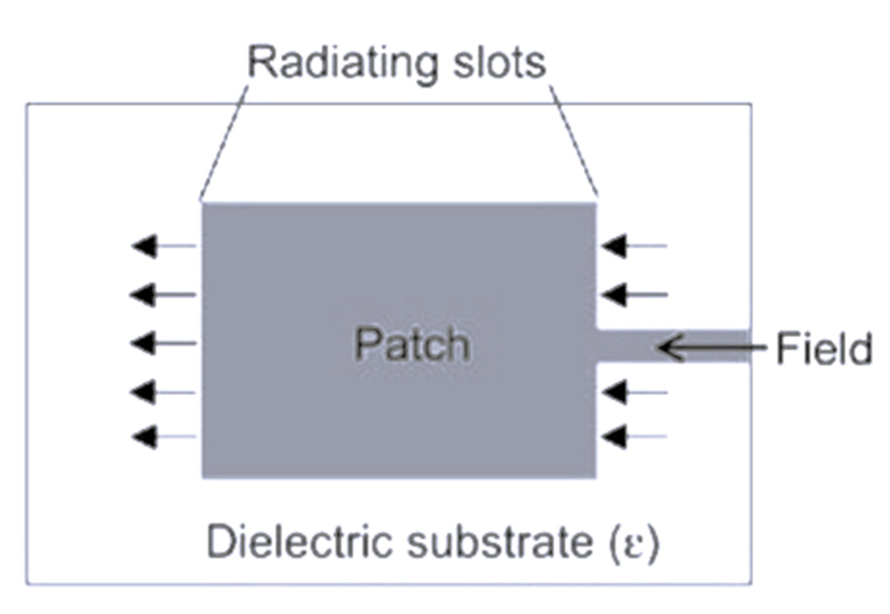
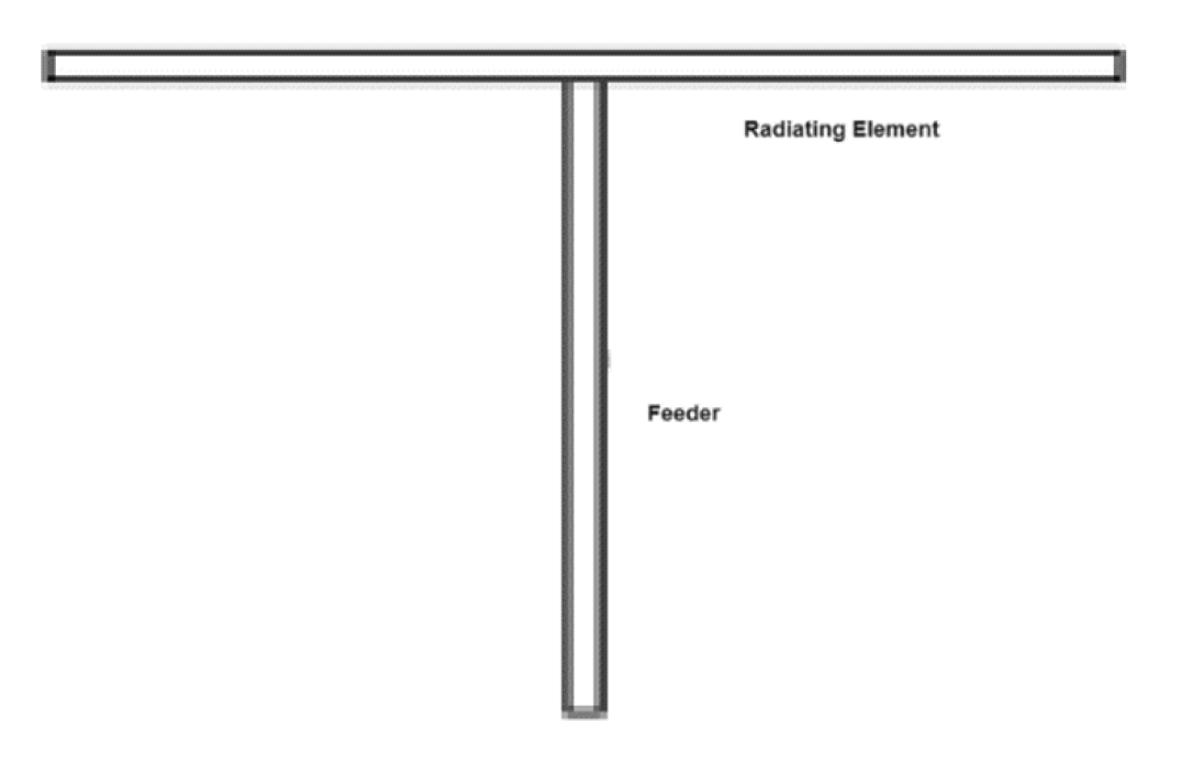
Microstrip antennas are printed antennas that function on the same principles as microstrip transmission lines. They consist of a radiating element put on top of a dielectric substance used as a substrate in between the ground and radiating patches, with a ground plane attached to the other side of the antenna design (Saeed & Nwajana, 2024).
Figure 1.
Patch Antenna top-view.
Figure 1.
Patch Antenna top-view.
Figure 2.
Patch Antenna side-view.
Figure 2.
Patch Antenna side-view.
These antennas are popular in applications that need a small form factor, such as mobile devices, satellite communication, and wearable technology (James & Hall, 1989). Their planar shape enables simple integration with printed circuit boards, making them a popular alternative for current electronic systems (Garg et al., 2001). Edge feeding, insect feeding, and aperture coupling are some of the approaches for feeding microstrip antennas. These feeding strategies enable control over the phase and amplitude of the current distribution on the patch, influencing the radiation pattern and facilitating beam steering (Wang et al., 2022).
Dipole antennas, consisting of two conducting components, are known for their simplicity, omnidirectional emission patterns, and wide operational bandwidth (Kraus & Marhefka, 2002). Dipoles, one of the oldest and most fundamental antenna designs, are widely used in a variety of wireless communication systems such as radio broadcasting, television transmission, and wireless networking (Stutzman & Thiele, 2012).
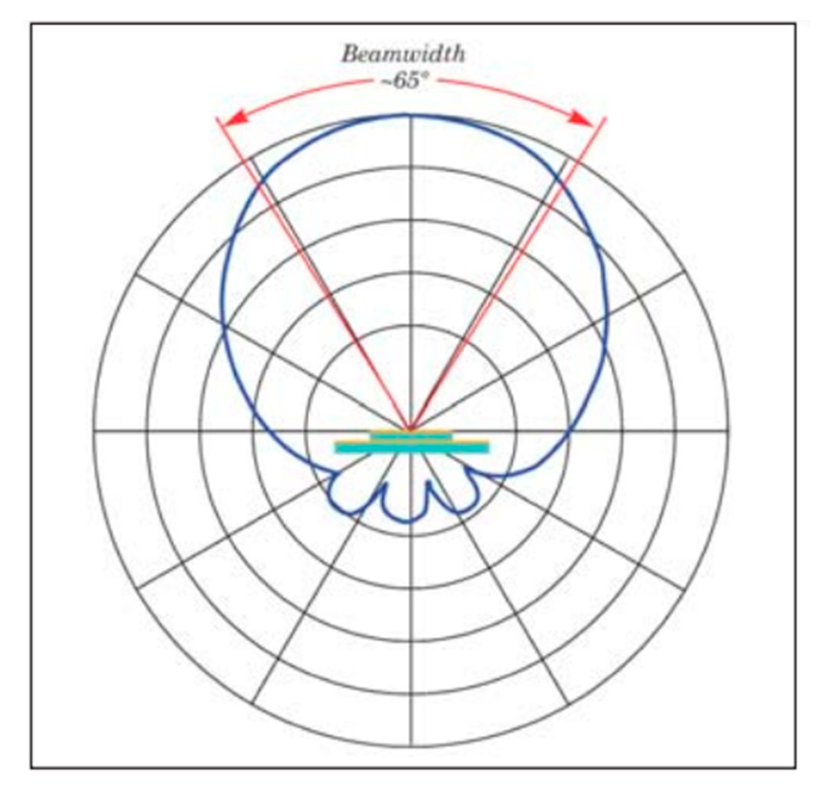
Figure 2.
Dipole Antenna.
Figure 2.
Dipole Antenna.
It is divided into two categories: short dipole antennas and folded dipole antennas. The term "short" in antenna engineering always refers to wavelength. In terms of frequency, the size of the wire connected to wavelength is more important than the size of the antenna. The dipole antenna’s gain rises as the wavelength grows. For best gain, the dipole should be larger than the wavelength. The folded dipole antenna consists of two parallel conductor wires that are linked together to form a loop (Vipul N., & Sharma S., 2017).
Their simple design and predictable performance characteristics make them common in both academic research and commercial applications. They can have odd and even modes, with classical theory focusing on odd modes due to high input impedances. Recent advancements allow simultaneous excitation of both modes using innovative feeding structures, enabling tuning of resonant frequencies through unique indentation and out dentation techniques. These principles enable efficient coverage of various frequency bands for applications like IoT and 5G systems (Xiao et al., 2022) Additionally, dipole antennas can utilize reflectors like three-dimensional photonic crystals to increase radiating gain and improve communication performance (Cheol et al., 2016).
OBJECTIVES
This comparative literature analysis will evaluate two types of antennas used in wireless communication: patch antennas and dipole antennas. Specifically, the objectives include:
Gather comprehensive literature reviews on Patch Antennas and Dipole Antennas from credible academic sources like Google Scholar.
-
Systematically compare the gathered data against numerous parameters, including
- a.
Antenna design parameters
- b.
Physical dimensions
- c.
Material Composition
- d.
Operating Frequency Bands
- e.
Radiation Patterns
-
Evaluate their performance measures, with an emphasis on
- a.
Gain
- b.
Bandwidth
- c.
Efficiency
- d.
Directivity
- e.
Impedance Matching
Investigate their specific applications and future use cases in wireless communication networks.
Identify and examine the limits of each antenna type.
METHODOLOGY
This comparative literature analysis uses a systematic framework to investigate Patch Antennas and Dipole Antennas in wireless communication. The first step is to do a thorough search for academic papers, journals, and technical reports on Patch and Dipole Antennas in credible databases. To guarantee thorough coverage of relevant literature, keywords like "Patch Antenna," "Dipole Antenna," "wireless communication," "antenna design," "antenna performance," and "radiation patterns" are used.
Once the appropriate literature has been collected, the following step is to extract and organize critical information. This provides information on the design parameters, physical dimensions, material composition, operational frequency ranges, and radiation patterns of both patch and dipole antennas. The retrieved data is arranged in a structured manner and categorized by important factors for ease of comparison.
Performance metrics are another important component of the comparison study. The research evaluates gain, bandwidth, efficiency, directivity, and impedance matching for both patch and dipole antennas. This examination aids in determining the performance advantages and disadvantages of each antenna type. Furthermore, the applications and possible use cases of Patch and Dipole Antennas in wireless communication systems are investigated, offering insights into their practical value.
Furthermore, the process includes identifying and analyzing the limits of each antenna type. This comprehensive method offers a clear grasp of the distinctions between Patch and Dipole Antennas, providing useful insights for improving the design and implementation of wireless communications systems.
DATA AND ANALYSIS
I. Antenna Design Parameters
| Antenna Design Parameters |
Antenna |
| Patch Antenna |
Dipole Antenna |
| Number of elements |
Patch antennas can be used both singly and in arrays. The number of elements in an array design might vary based on the application and performance requirements. Arrays frequently contain numerous patch parts to improve gain and directivity (Balanis, 2016). |
A standard dipole antenna comprises two elements, each usually a quarter-wavelength long, making the total length of the dipole half a wavelength. Dipole arrays can be formed by arranging numerous dipole components to improve performance (Kraus & Marhefka, 2002). |
| Geometry configuration |
Patch antennas are usually rectangular or circular in form, however alternative geometries such as triangular, elliptical, and more complicated shapes are utilized to obtain certain radiation characteristics. They are typically planar, with a radiating patch on one side of a dielectric substrate and a ground plane on the other (Garg et al. 2001). |
The traditional dipole antenna is straight and linear, made up of two conducting parts aligned collinearly. Folded dipoles have a similar radiation pattern but differing impedance characteristics. The dipole’s design is simple, which contributes to its widespread use (Stutzman & Thiele, 2012). |
| Frequency band(s) of operation |
Patch antennas may operate at a broad range of frequencies, often from 1 GHz to 60 GHz, depending on the design and application. They are frequently utilized in applications such as GPS (1.575 GHz), Wi-Fi (2.4 and 5 GHz), and millimeter-wave communications (28 and 60 GHz) (James & Hall, 1989). |
Dipole antennas may operate across a wide frequency range, often from low (LF) to very high (VHF) and beyond. They are widely utilized in the HF (3-30 MHz), VHF (30-300 MHz), and UHF (300 MHz-3 GHz) bands. They are widely employed in FM broadcasting (88-108 MHz) and television reception (54-216 MHz) (Kraus & Marhefka, 2002). |
| Beamforming technique |
Beamforming using patch antennas is frequently accomplished using phased array methods, in which the relative phase of the signal feeding each antenna element in an array is modified to guide the beam in the intended direction. This enables dynamic modification of the radiation pattern, as well as increased signal intensity and coverage (Balanis 2016).
|
Beamforming with dipole antennas is possible using antenna arrays, which are carefully positioned and fed with various phase shifts. This approach enables the radiation pattern to be steered or sculpted to fulfill specific coverage needs. Yagi-Uda arrays are a common example of such setups, which are frequently employed for television reception and amateur radio (Stutzman and Thiele, 2012).
|
II. Applications
A. Patch Antenna
1. Design of Microstrip Patch Antenna for Radar and 5G Applications
In this study, it examined the evolution of mobile wireless technology from 1G to 4G, as well as the current transition to 5G, which is being driven by the desire for larger data rates and improved wireless connection. The 5G technology has numerous significant advantages, including more bandwidth, greater cell resolution, and the capacity to link millions of devices. In addition, the utilization of Ku-band antennas in 5G research, as well as the benefits of microstrip patch antennas, which are commonly used in mobile phones and other applications due to their small size, low cost, and lightweight nature.
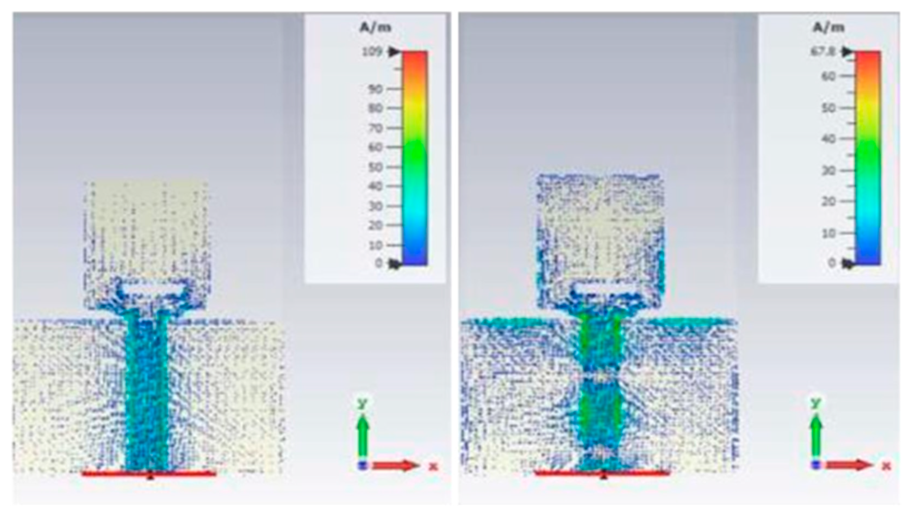
Figure 6.
Simulated surface current at 3.1 GHz for slot width of 5m.
Figure 6.
Simulated surface current at 3.1 GHz for slot width of 5m.
Using the CST Microwave Studio simulator program, the basic microstrip patch runs at 3.1 GHz in a single band, with a return loss of -10dB, a bandwidth of 900 MHz, and a gain of 7.57 dB. (Without rectangular slots). With the inclusion of rectangular slots,
The antenna has evolved into a dual-band antenna, with one band’s attributes similar to those of the previous version. The suggested antenna designs were intended to give good performance in terms of gain and bandwidth while maintaining a reflection coefficient of roughly -10dB (Hussein & Hussein, 2023).
2. Wide-Band E-Shaped Patch Antennas for Wireless Communication
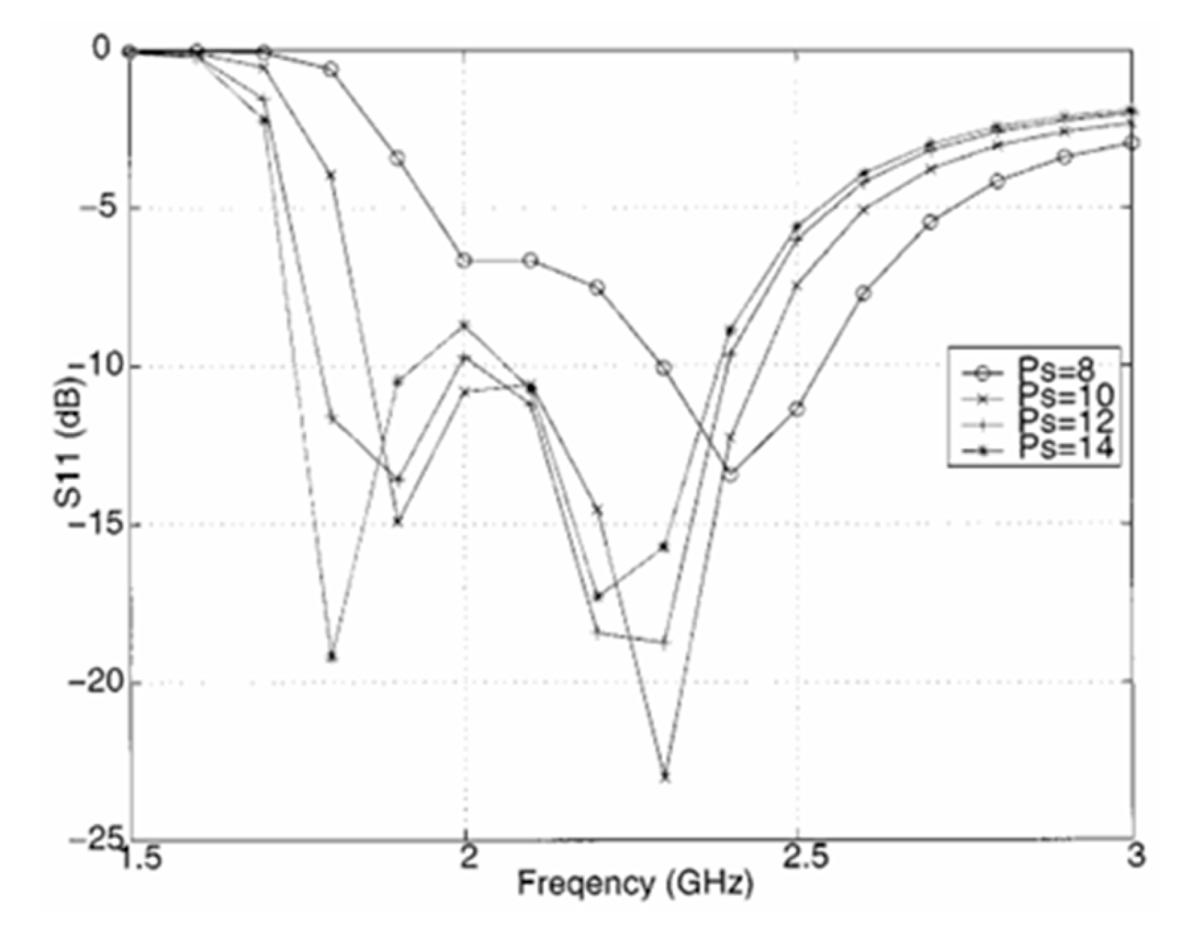
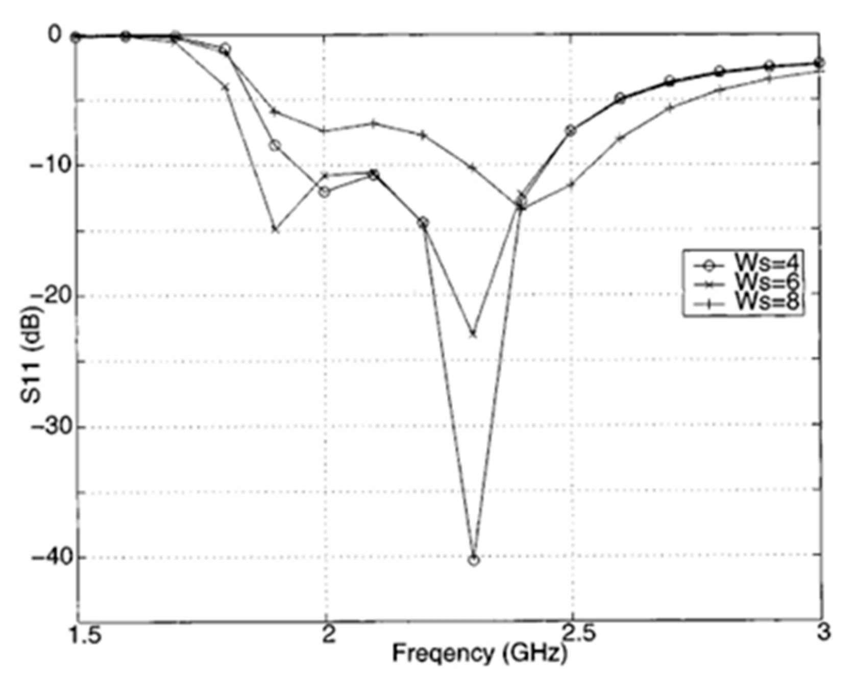
The wide-band mechanism investigates the behavior of the currents on the patch. The slot’s width and length and spot are tuned for a broad bandwidth. A 30.3% E-shaped patch antenna resonating at wireless communication frequencies of 1.9 and 2.4 GHz is developed, built, and tested. The Calculated E-shaped patch antennas with different slot positions and widths also demonstrated below .
Figure 7.
Calculated E-shaped patch antennas with different slot positions.
Figure 7.
Calculated E-shaped patch antennas with different slot positions.
Figure 8.
Calculated E-shaped patch antennas with different slot widths.
Figure 8.
Calculated E-shaped patch antennas with different slot widths.
As the slot length increases, a lower resonance frequency occurs. The second resonant frequency decreases as the slot length increases. The slot length is a crucial element for determining the resonant frequencies of an E-shaped patch antenna. When is tiny, the lower frequencies do not match well. When becomes greater, the two resonant frequencies become recognizable, and a broad-band match is achieved. As the size increases, the difference between two resonant frequencies might exceed dB. The antenna operates in a dual-frequency mode rather than wide-band mode. Therefore, is a valuable parameter to alter the matching to 50 (Yang, et.al., 2001).
3. Wideband Patch Array Antenna for Aerospace Communication
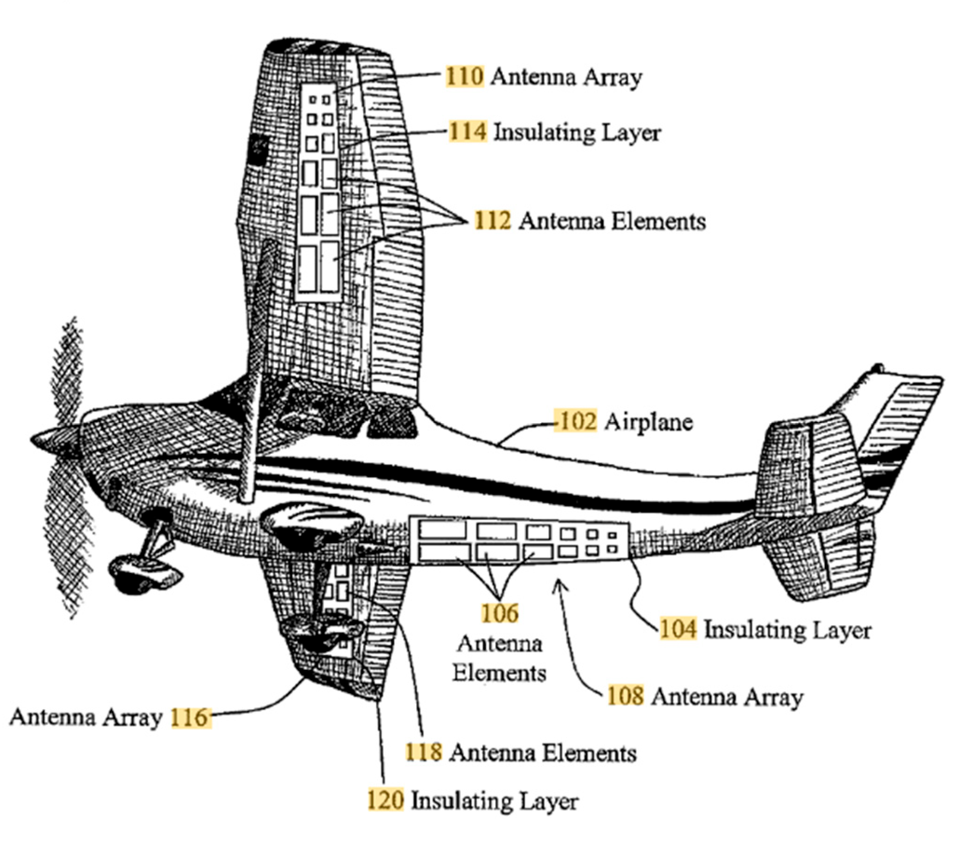
Patch antennas play an important role in improving communication in aircraft applications because to their distinct design features and performance characteristics. Patch antennas have numerous applications in aerospace, particularly in the field of Unmanned Aerial Vehicles (UAVs) and airborne measurements. Several studies have focused on improving the performance of patch antennas used in aeronautical applications. For example, one study presented a patch antenna design incorporating parasitic elements in the superstrate to boost bandwidth and gain, which is appropriate for mobile and aerospace applications (Reddy et al., 2023). Another research study explored the design of a wideband patch array antenna for UAV communication, highlighting the need of high gain and wide bandwidth in addressing UAV communication requirements, which were accomplished via proximity coupling techniques and array configurations (Fauzi et al., 2023). The figure below shows the integration of antennas onto the surface of an airplane without significantly affecting its aerodynamic shape (Donald B., 2014).
Figure 9.
Integration patch antenna array in the surface of airplane.
Figure 9.
Integration patch antenna array in the surface of airplane.
B. Dipole Antenna
1. Dipole Antenna in Mobile Communications
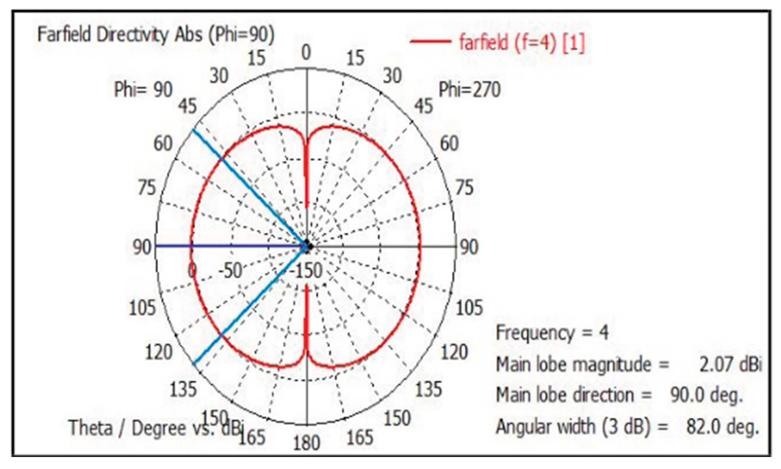
Dipole antennas have numerous applications in mobile communications. They are used to create dual-polarized base station antennas for 5G applications, with low input impedance and great port-to-port isolation (Gao et al., 2022). In mm-Wave communications, MIMO dipole pairs are used to improve performance in mobile devices by optimizing the envelope correlation coefficient (ECC) and mean effective gain (MEG) (Kim, 2022). Furthermore, narrow impedance dipoles are suited for GSM and WiMAX ranges, making them useful in smartphones, electronic devices, and base stations (Berdnik et al., 2021).
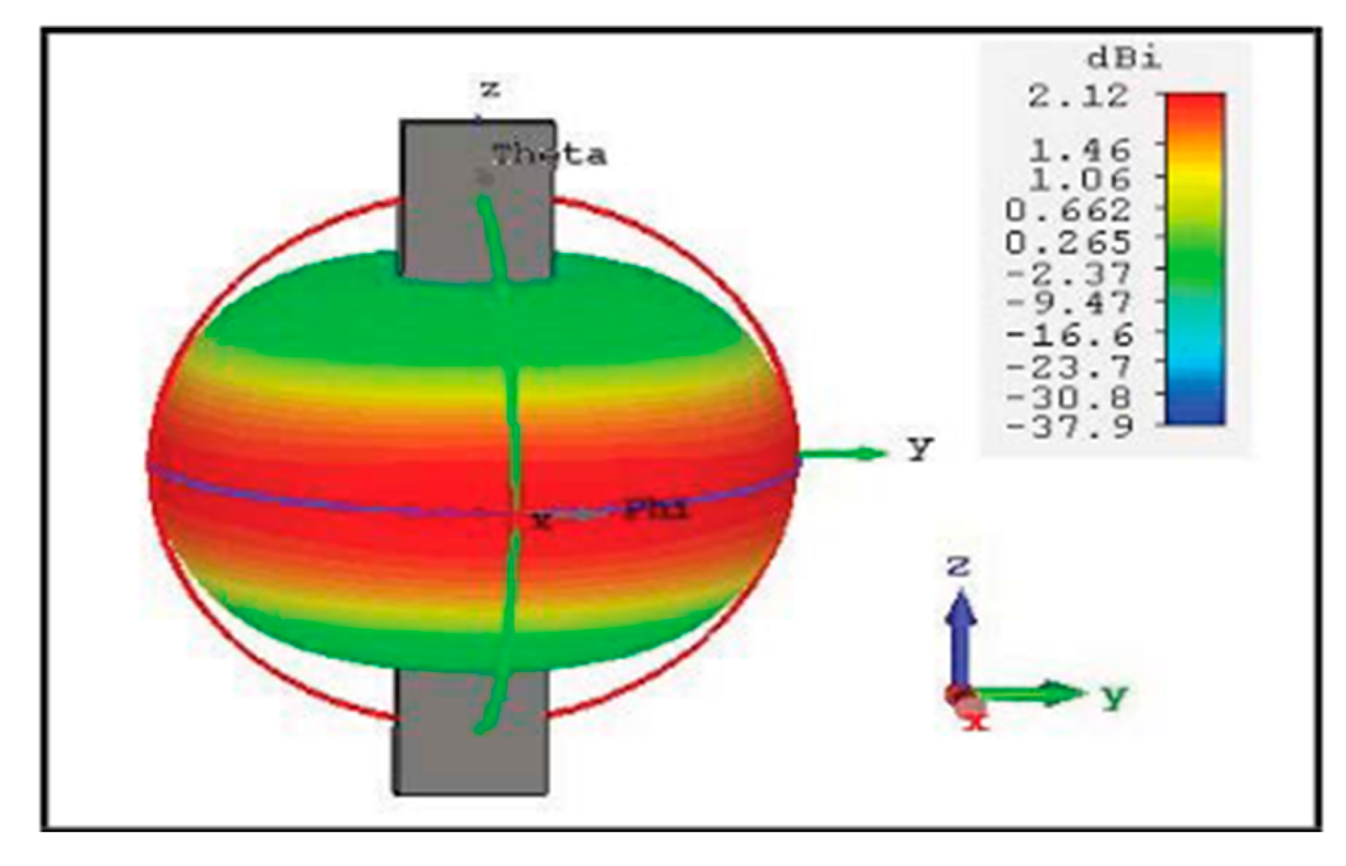
Figure 10.
Radiation pattern of dipole antenna in Ultra-Wide band Antenna.
Figure 10.
Radiation pattern of dipole antenna in Ultra-Wide band Antenna.
Furthermore, redesigned dipole antenna structures, which operate at 26 GHz, have advantages in size reduction, gain optimization, bandwidth, and radiation efficiency, making them viable for mobile applications beyond 5G (Perarasi et al., 2021).
2. Development of Dipole Antenna in Television Broadcasting
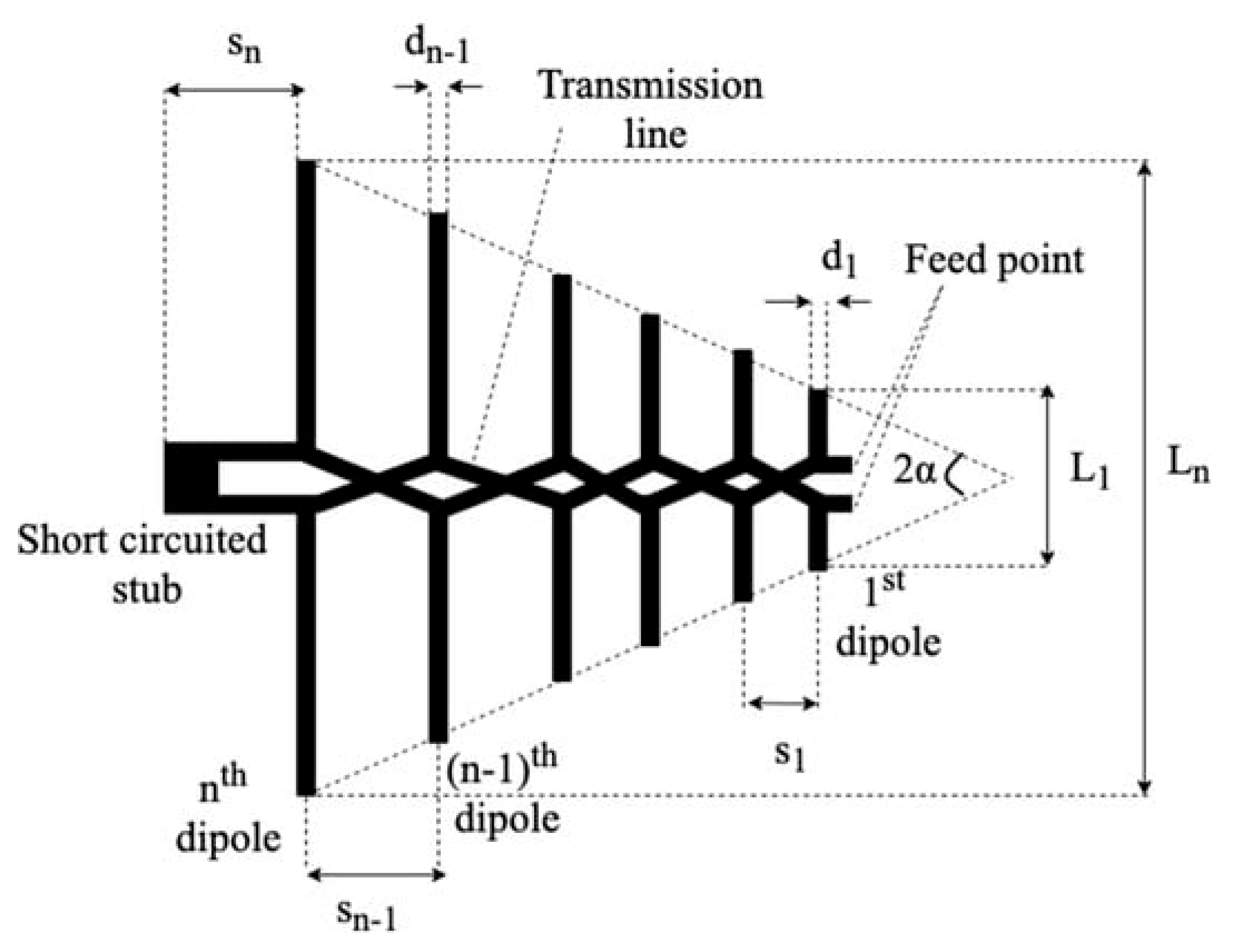
Dipole antennas in television broadcasting have advanced significantly over the last decade. Researchers have investigated a variety of approaches for improving the performance of dipole antennas, including employing I-shape addition techniques and horn waveguides to broaden the frequency range and increase gain (Naktong & Wattikornsirikul, 2022). LPDAs (Log Periodic Dipole Arrays), or simply log-periodic antennas, have been widely employed for TV reception since the 1960s due to their good wideband characteristics and strong directivity, despite the fact that their peak gain is generally lower than that of similar size Yagi-Uda antennas (Zaharis et al, 2021).
Figure 11.
Geometry of a conventional LPDA (Log Periodic Dipole Array) proposed by Carrel.
Figure 11.
Geometry of a conventional LPDA (Log Periodic Dipole Array) proposed by Carrel.
Furthermore, antennas with omni-directional radiation patterns and high antenna gains that can cover the DTV frequency band have been created through the design of wideband dipole antennas using slot etching and matching techniques (Komsing et al, 2021). The introduction of dipole array antennas with drilled spaces between radiators has enhanced radiation patterns and beamwidth, making them ideal for mass production while also improving broadcasting performance (Choi et al, 2021).
3. Dipole Antenna System Application to FM BROADCASTING
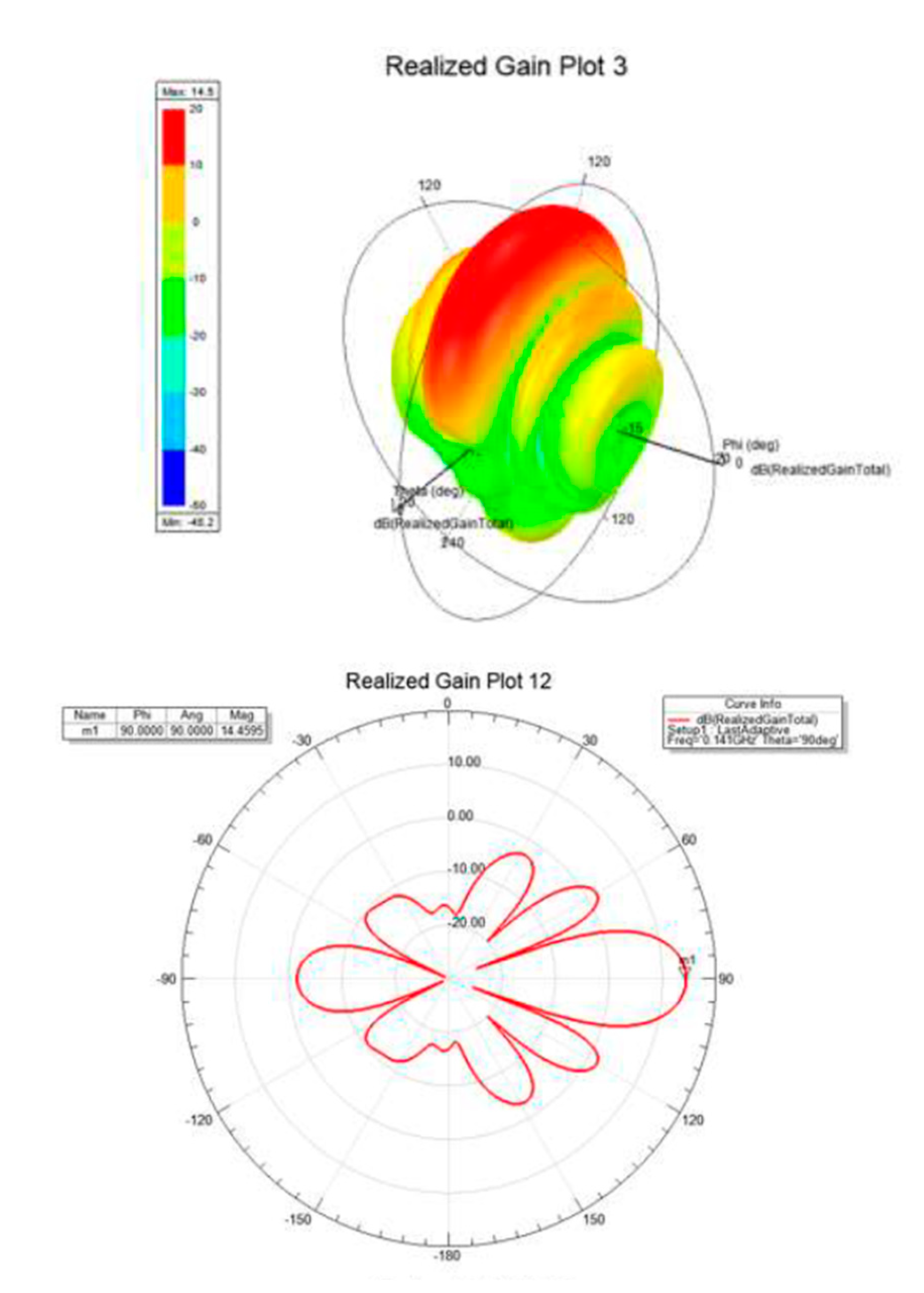
Dipole antennas are important in FM broadcasting because of their efficiency and performance. FM broadcasting systems use a variety of dipole antennas, including single and double dipoles, which provide advantages in terms of bandwidth, gain, and standing wave ratio (Q. Liu et al., 2020).
Figure 12.
Simulation of FM Dual Dipole Antenna and Array.
Figure 12.
Simulation of FM Dual Dipole Antenna and Array.
In addition, integrated dipole antennas constructed specifically for FM broadcast and terrestrial-digital multimedia broadcast (T-DMB) frequencies have been developed, demonstrating dipole antennas’ versatility across many broadcasting technologies (Kim et al., 2018). These studies demonstrate the various applications and benefits of dipole antennas in FM broadcasting systems.
III. Limitation
This antenna comparison review has a few limitations. The focus was limited to literature available in scientific journals and conference proceedings, potentially excluding crucial advances reported in proprietary sources. The studied antennas span multiple technical generations, making direct comparisons difficult due to changes in underlying technologies and testing conditions. Performance metrics are frequently context-dependent, and discrepancies in testing conditions might compromise reliability. The arbitrary character of evaluation criteria, along with the quick speed of technical innovation, complicates meaningful comparisons. Moreover, the review may not sufficiently address niche applications, and data completeness varies between studies. Geographical and environmental factors influencing performance were not consistently accounted for, and potential publication bias toward positive outcomes could distort the data. Finally, time and resource restrictions limited the scope of the assessment, highlighting the need for further in-depth future research.
CONCLUSIONS
Patch antennas and dipole antennas are two typical types of antennas that have distinct properties. Patch antennas are distinguished by their low profile and large bandwidth. They frequently show strong gain and stable radiation patterns over a wide frequency range. Dipole antennas, on the other hand, are known for their basic structure consisting of two conducting parts and are frequently employed in a variety of applications. Dipole antennas are distinguished by their omnidirectional radiation pattern and ease of construction. Patch antennas are preferred for their small size and wide bandwidth, although dipole antennas are popular for their simplicity and omnidirectional radiating properties.
Patch antennas are compact and easy to integrate, making them suitable for enclosed environments in wireless sensor networks. They are also used in high-speed wireless communication systems, where directivity and radiation pattern control are crucial. Dipole antennas, on the other hand, are used in high-speed communication systems, mobile phones, and broadcasting systems. Patch antennas excel in enclosed settings and sensor networks, while dipole antennas are preferred for controlled radiation patterns and high-speed communication systems. The decision between patch and dipole antennas is ultimately determined by specific requirements such as frequency range, size limits, and environmental circumstances. Future study should focus on these antenna types, taking into account evolving technologies and application situations, in order to improve their comparative evaluation and maximize their deployment in a variety of communication systems.
RECOMMENDATION
Multiple recommendations are made for future comparisons of patch and dipole antennas. Expanding the literature review to incorporate both established and new studies will provide a complete picture of the current state of various antenna types. Standardizing performance criteria such as gain, bandwidth, efficiency, and radiation pattern, as well as maintaining uniform testing settings, will improve the reliability of comparisons. Including a broader range of application scenarios, such as telephony, satellite communications, and IoT, will serve to demonstrate the versatility and limitations of each antenna type in various circumstances. Addressing geographical and environmental aspects influencing performance, as well as incorporating interdisciplinary insights from materials science and electrical engineering, will provide a comprehensive perspective.
Additionally, supporting the inclusion of both positive and negative results in published research will reduce prejudice and provide a more balanced perspective. Allocating enough time and resources to the review will result in a full and extensive analysis, allowing for more informed conclusions concerning the comparative benefits of patch and dipole antennas.
References
- Ahn, Bierng, Chearl., Jo, Sang, Woo., Park, Cheol, Su. (2016). A dipole antenna.
- Balanis, C. A. (2016). Antenna theory: Analysis and design (4th ed.). John Wiley & Sons.
- Berdnik, S., Katrich, V., Nesterenko, M., & Dumin, O. (2021). Triple-Band Dipole Antenna for Wireless Communication Systems. 2021 IEEE 3rd Ukraine Conference on Electrical and Computer Engineering (UKRCON). [CrossRef]
- Breed G. (2009, March). The Fundamentals of Patch Antenna Design and Performance. Summit Technical Media, LLC.
- Bevelacqua, P. (2008). Antenna Arrays: Performance Limits and Geometry Optimization [Doctoral dissertation, Arizona State University].
- Choi, Jae, Hoon., Lee, Ho, Joo., Kim, Sung, Peel. (2021). Dipole Array Antenna.
- Chen, P., Wang, L., Lin, Y., & Wang, D. (2022). Dual-band dual-polarized dipole antenna for gain and isolation enhancements. Applied Computational Electromagnetics Society Journal. [CrossRef]
- C. Yao et al., "Frequency Reconfigurable Planar Filtering Dipole Antenna with Omnidirectional Radiation Pattern," 2022 IEEE 10th Asia-Pacific Conference on Antennas and Propagation (APCAP), Xiamen, China, 2022, pp. 1-2. [CrossRef]
- Donald, M., Bishop. (2014). Airplane patch antenna.
- F. Yang, Xue-Xia Zhang, Xiaoning Ye and Y. Rahmat-Samii, "Wide-band E-shaped patch antennas for wireless communications," in IEEE Transactions on Antennas and Propagation, vol. 49, no. 7, pp. 1094-1100, July 2001. [CrossRef]
- Garg, R., Bhartia, P., Bahl, I., & Ittipiboon, A. (2001). Microstrip antenna design handbook. Artech House.
- Hussein, O. D., & Hussein, A. A. (2023). Design of microstrip patch antenna for radar and 5G applications. ESP Journal of Engineering & Technology Advancements, 3(2), 7–19. [CrossRef]
- James, J. R., & Hall, P. S. (1989). Handbook of microstrip antennas. Peter Peregrinus Ltd.
- Kim, J. (2022). Printed dipole MIMO pair for mobile platforms in mm-Wave communications. 2022 IEEE International Symposium on Antennas and Propagation and USNC-URSI Radio Science Meeting (AP-S/URSI). [CrossRef]
- Kim, Do, Hyun., Kim, Hwan, Ui., Kang, Seong, Gu., Park, Young, Il. (2018). FM Frequency Modulation and Terrestrial-Digital Multimedia Broadcast combined folded-dipole antenna.
- K. Pavan Reddy, S. Satya Sai, P. Rakhesh and Y. Sudarsana Reddy, "Design of Microstrip Patch Antenna for Bandwidth and Gain Enhancement using Parasitic Patches in Superstrate," 2023 4th International Conference for Emerging Technology (INCET), Belgaum, India, 2023, pp. 1-4. [CrossRef]
- Kraus, J. D., & Marhefka, R. J. (2002). Antennas: For all applications (3rd ed.). McGraw-Hill.
- L. Zhang and P. Yu, "High-Gain Magnetic Dipole Antenna by Loading Metalmaterials," 2021 International Applied Computational Electromagnetics Society (ACES-China) Symposium, Chengdu, China, 2021, pp. 1-2. [CrossRef]
- M. H. Fauzi, I. Kustiawan, N. F. A. Hakim, S. Herfiah, R. S. Asthan and A. Munir, "Design and Implementation of Wideband Patch Array Antenna for Unmanned Aerial Vehicle Communication," 2023 International Conference for Advancement in Technology (ICONAT), Goa, India, 2023, pp. 1-6. [CrossRef]
- M. Wang, W. Tang, X. Li and Z. Chen, "A Single Feed Wideband Circularly Polarized Dipole Antenna with Wide Beamwidth," 2022 IEEE MTT-S International Microwave Workshop Series on Advanced Materials and Processes for RF and THz Applications (IMWS-AMP), Guangzhou, China, 2022, pp. 1-3. [CrossRef]
- Naktong, W., & Wattikornsirikul, N. (2022). DIPOLE ANTENNA WITH HORN WAVEGUIDE FOR ENERGY HARVESTING IN DTV SYSTEMS. Progress in Electromagnetics Research M. Pier M, 111, 145–157. [CrossRef]
- Orban D. & Moernaut G.J.K (2017). The Basics of Patch Antenna. Orban Microwave Products. https://its-wiki.no/images/3/36/UNIK4700-Antennas.pdf.
- Perarasi, T., Ali, K., Moses, M. L., Poongodi, C., Deepa, D., & Gayathri, R. (2021). Design of Meander Dipole antenna structure for 5G wireless applications. 2021 Smart Technologies, Communication and Robotics (STCR). [CrossRef]
- P. Gao, Y. Xu, H. Ma, C. Wang, C. Sun and J. Tong, "Design of a Dual-Polarized Antenna with PPW and Dipole for 5G Application," 2022 IEEE MTT-S International Microwave Workshop Series on Advanced Materials and Processes for RF and THz Applications (IMWS-AMP), Guangzhou, China, 2022, pp. 1-2. [CrossRef]
- Q. Liu et al., "Performance Analysis of FM Dipole Antenna and Array," 2020 International Wireless Communications and Mobile Computing (IWCMC), Limassol, Cyprus, 2020, pp. 188-190. [CrossRef]
- Q. H. Hao, S. Y. Zheng and K. Lu, "A Magneto-Electric Dipole Antenna Array With Flat-Top Radiation Patterns," 2022 IEEE Conference on Antenna Measurements and Applications (CAMA), Guangzhou, China, 2022, pp. 1-3. [CrossRef]
- Saeed, M. A., & Nwajana, A. O. (2024). A review of beamforming microstrip patch antenna array for future 5G/6G networks. Frontiers in Mechanical Engineering, 9. [CrossRef]
- S. Komsing, N. Fhafhiem, A. Innok and A. Ruengwaree, "Design of Wide-Band Dipole Antenna for Digital TV Broadcasting Application," 2018 International Electrical Engineering Congress (iEECON), Krabi, Thailand, 2018, pp. 1-4. [CrossRef]
- Stutzman, W. L., & Thiele, G. A. (2012). Antenna theory and design (3rd ed.). John Wiley & Sons.
- Tewary, T., Maity, S., Mukherjee, S., Roy, A., Sarkar, P. P., & Bhunia, S. (2022). High gain miniaturrized super-wideband microstrip patch antenna. International Journal of Communication Systems, 35(11). [CrossRef]
- Tiwari, R., Sharma, R., & Dubey, R. (2020). Microstrip patch Antenna Array Design AnaylSis for 5G communication applications. Smart Moves Journal Ijoscience, 6(5), 1–5. [CrossRef]
- Vipul N. & Sharma, S. (2017). A Journey of Antenna from Dipole to Fractal: A Review. Journal of Engineering Technology. https://www.researchgate.net/profile/Narinder-Sharma7/publication/319127373_A_Journey_of_Antenna_from_Dipole_to_Fractal_A_Review/links/5a297dcba6fdccfbbf81730a/A-Journey-of-Antenna-from-Dipole-to-Fractal-A-Review.pdf.
- Xiao, B., Wong, H., Li, M., Wang, B., & Yeung, K. L. (2022). Dipole antenna with both odd and even modes excited and tuned. IEEE Transactions on Antennas and Propagation, 703), 1643–1652. [CrossRef]
- Zaharis, Z.D.; Skeberis, C.; Xenos, T.D.; Lazaridis, P.I.; Stratakis, D.I. IWO-based synthesis of log-periodic dipole array. In Proceedings of the 2014 International Conference on Telecommunications and Multimedia (TEMU), Heraklion, Greece, 28–30 July 2014; pp. 150–154.
|
Disclaimer/Publisher’s Note: The statements, opinions and data contained in all publications are solely those of the individual author(s) and contributor(s) and not of MDPI and/or the editor(s). MDPI and/or the editor(s) disclaim responsibility for any injury to people or property resulting from any ideas, methods, instructions or products referred to in the content. |
© 2024 by the authors. Licensee MDPI, Basel, Switzerland. This article is an open access article distributed under the terms and conditions of the Creative Commons Attribution (CC BY) license (http://creativecommons.org/licenses/by/4.0/).
