1. Introduction
Mobile manipulators, which combine a mobile base platform and a serial manipulator, are becoming increasingly popular in various applications due to their flexibility and adaptability when operating in diverse environments [
1,
2].
To ensure their efficient and reliable operation, it is crucial to choose movement algorithms that take into account the unique characteristics of both the mobile platform and the serial manipulator. While researchers work on combining base and manipulator movement [
3], also physical limitations of mobile manipulators have to be considered. Mobile platform movement of wheeled mobile robots is imprecise in comparison to the movement of serial manipulators due to friction and slip between wheel and ground contact [
4]. Furthermore, a safety-related reduction of velocity further highlights the need to study a division of a mobile manipulator into two subsystems. Combining their movements can lead to inaccurate positioning and potentially hazardous situations and much more complexity in the system. In this paper a simplified approach, as opposed to a holistic one, is used to find a suitable position for the mobile platform that allows for efficient and safe manipulation while ensuring optimal performance of the mobile platform and the manipulator. The combination of a mobile robot platform with a manipulator results often in a degree of freedom (DOF) greater than six and must be described as a robotic system with kinematic redundancy [
5,
6] for a certain task in three dimensional space where a DOF of six would be sufficient. However, the inherent complexities and uncertainties in these systems pose several challenges in realizing their full potential.
Different from conventional, stationary industrial robots which have often a DOF equal to six, redundant robots, as described above, can move while the position and orientation of the end-effector (EE) are fixed. Another advantage of such kinematically redundant systems is collision avoidance, while the EE follows a specific path [
7]. Therefore, such systems can be used for technically difficult dexterity tasks, such as grasping inside a tube or picking between two walls. The workspace of a stationary industrial robot is not only limited by the arm length but also by the allowed joint torques. The placement of a robotic manipulator base has to be done adequate to the task which should be fulfilled by the robotic system. For mobile manipulators, this is even more challenging since the base of the robot manipulator can be moved. This also brings the possibility to change the manipulator base for each task in respect to the task constraints. A human worker knows by nature how to operate during different tasks. He utilizes his arm redundancy to take a comfortable arm position [
8]. For example, soldering on a printed circuit board will be done with bent elbows in front of the body with a certain distance to ensure a good view. This position allows the worker optimal handling of tools. One could name this the ’human work comfort zone’ for this specific task. Modern mobile robots can be equipped with collaborative manipulators to fulfill different tasks as e.g. pick and place or transportation. This type of manipulator is specially designed to be used beside humans and to cooperate with human workers. However with some additional restrictions to speed, force and torque of these mobile platforms, they can be called collaborative mobile manipulators (see ISO15066 and ISO10218).
The selection of a suitable path and a suitable path goal for a mobile manipulator is a crucial aspect of its operation, as it directly affects the robot’s ability to perform tasks and its overall manipulability. In recent years, various approaches have been proposed in the literature to determine the optimal path for mobile manipulators.
For example [
9,
10,
11] divides the problem and separates the mobile manipulator into two independent subsystems: the mobile base and the mounted serial manipulator. The authors of [
12,
13] use a different approach to combine the mobile base and the manipulator into one system with a higher number of DOF, well-known and often used sampling-based planners are used in multiple variations within this approach. Sampling based planners like the Rapidly-exploring Random Tree (RRT) [
14], the Probabilisitic Road Map (PRM) [
15] and the Expansive-Spaces Tree planner (EST) [
16] or any of their variants (RRT-Connect, RRT-GoalBias, Informed RRT,...) have been used due to their ability to handle high-dimensional spaces. Those types of planners have been utilized for mobile manipulators where the entire system is treated as a single high DOF system during the planning process. Other types of planners minimize a certain cost function; Covariant Hamiltonian Optimization for Motion Planning (CHOMP) [
17] and Stochastic trajectory optimization for Motion Planning (STOMP) [
18] algorithms are often used in the robotics motion planning framework MoveIt [
19]. Those planners use cost functions with various constraints like EE position and orientation as well as joint torques, joint limits and distance to obstacles (for collision avoidance).
As already mentioned by the authors before, finding an appropriate goal position for a mobile robot that satisfies a specific task is a challenging problem in robotics. The goal position has not only to be reachable by the robot, but must also meet limitations such as e.g. avoiding obstacles. To find an optimal solution, multiple factors such as the robot’s kinematic and dynamic properties, environment, and task requirements must be considered. In [
20], Sandakalum et al. give a comprehensive review of the current state-of-the-art path planning of mobile manipulators as well as in determining the mobile base goal position in general. To find a suitable goal position of the mobile base and as well as a goal configuration of the mounted manipulator, two different approaches should be mentioned: Firstly, the concept of a reachability map [
21] uses the reachable workspace of a mounted serial manipulator. Secondly, the so-called capability map by Zhang et al. [
22,
23]. This capability map uses the distribution of the manipulability, based on Yoshikawa [
24], in Cartesian space to guide the base placement of manipulators [
25].
In a previous work we defined the comfort zone as a region in the n-dimensional discrete joint space [
26]. Each point in the so defined comfort zone represents a certain joint configuration and fulfills a multi-objective optimization including various manipulability measures (velocity, force, and stiffness dependent). Furthermore, these points are constrained with minimum/maximum velocities, forces, and stiffness. This was shown for a planar mobile robot with two translational and three rotational joints as used in
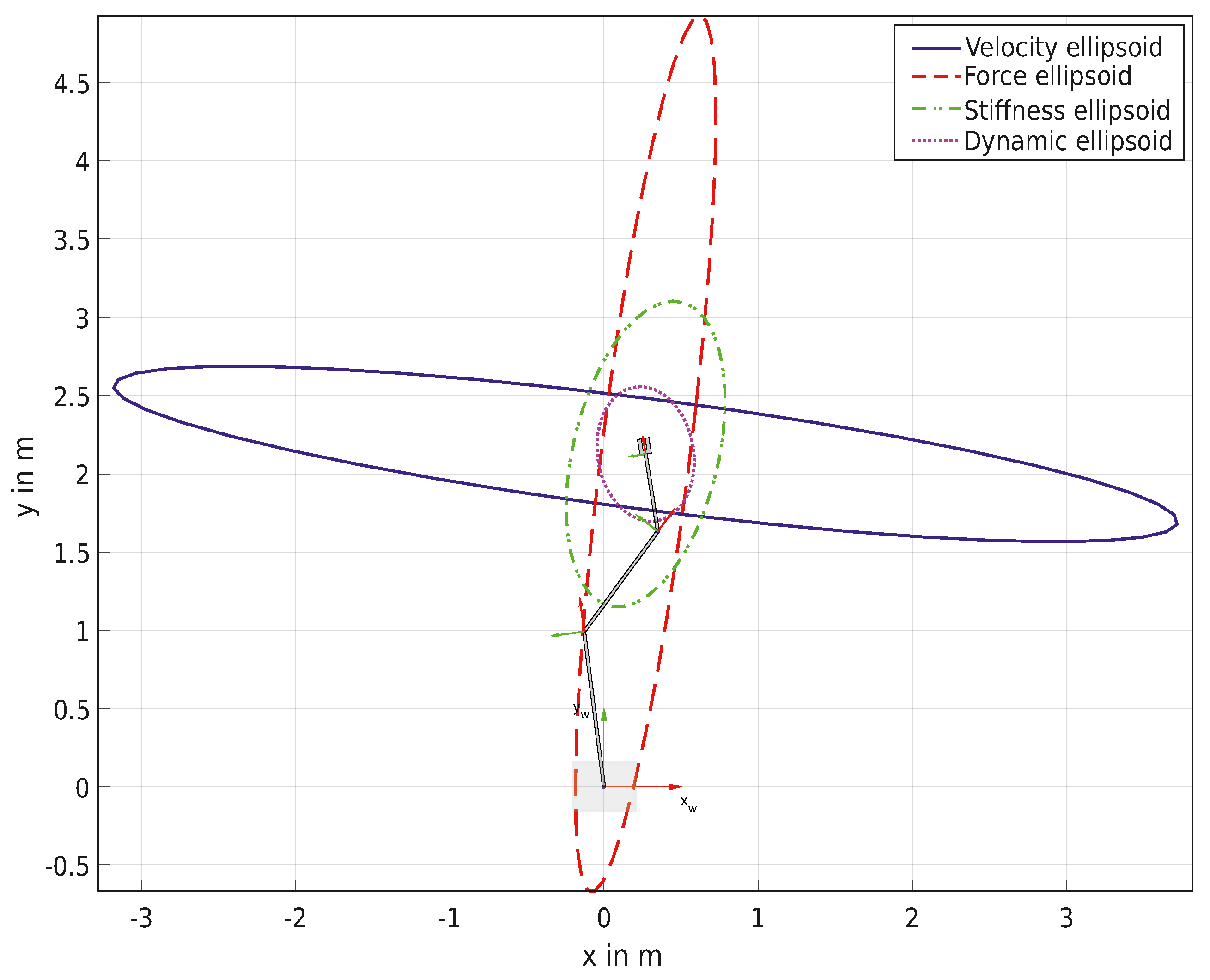
Figure 1.
In this paper we propose a further method to determine a zone of possible base positions (task dependent comfort zone) for a mobile manipulator that can be used with various individual manipulability measures, such as velocity, force, acceleration, and stiffness. Using these manipulability measures, we are able to evaluate the specific demands of different tasks and determine a zone of base positions (on a plane in Cartesian space) that can accommodate these demands. The capability of staying within this task dependent comfort zone ensures that the mobile manipulator can perform tasks effectively and efficiently, while also taking into account the need for high-speed movements, large forces, high accelerations, or high stiffness. Our results provide a comprehensive evaluation of the robot’s ability to perform tasks and offer specific guidelines for selecting appropriate base placement strategies. This enables task dependent autonomous positioning of the mobile manipulator in a variety of applications. The proposed method will be shown within an example task using different types of mobile manipulators, including different serial manipulator configurations and DOF.
This paper is organized as follows: In
Section 2 the Jacobian matrix is introduced and the various manipulability measures used to evaluate the robot’s performance for different tasks are described. The measures include velocity, force, acceleration, and stiffness dependent measures based on different already established approaches.
Section 3 incorporates the manipulability measures into the proposed method to determine the task dependent comfort zone, which represents a zone of possible positions for the mobile on a plane in Cartesian space.
Section 4 describes the evaluation of the proposed method using various mobile manipulators and arm configurations. Finally, the last section summarizes our findings and provides suggestions for future work.
3. Task Dependent Comfort Zone
In our previous work the comfort zone was defined by combining the manipulability measures with help of a multi-objective optimization [
26]. In this approach with a multi-objective optimization the problem rises that the used measures are related, and in some cases are inversely proportional. Here a different approach is considered to increase the variable usability of the proposed algorithm by choosing one measure at a time. However, care was taken to retain the possibility of performing a combination of the used measures.
3.1. Task Classification
In modern industrial environments the number and the need for human-robot interaction and thereby collaborative tasks continues to increase. Thus, tasks can be classified regarding requirements on the robotic system [
41]. As humans we can classify tasks regarding forces to our body arising from interactions with the environment. This can be done due to our great and fast sensory capabilities and by learning how to interact with the environment [
42]. To classify a robotic task, many different approaches are possible. For example, the motion constraints and the total force/torque acting on the system could be used [
43]. In
Table 2 we show a selection of tasks and try to classify them according to their velocity, force, stiffness, and acceleration requirements as to then choose the suitable manipulability measure for a certain task. Of course, these are just general examples and the specific requirements for each task will depend on the details of the task. It shows that our concept of task dependent comfort zone can be extended by using a different manipulability measure. Depending on the task, a directional manipulability measure [
44] may be preferable as opposed to the more general approach discussed in
Section 2.2.
3.2. Motivation
For any mobile manipulator, which is a combination of mobile robot platform and serial manipulator, the
joint variables can be separated as
where
p is the number of joints of the mobile platform and
m is the number of joints of the serial manipulator. Any pose of a mobile robot platform on a plane can be described with a three-dimensional vector
and
are the coordinates and
is the rotation around the local z-axis of the mobile robot. The pose of the EE of a robot manipulator can be described with
with
standing for the description of the orientation. We use Euler angles with rotation around (
)-axis and
is the position of the EE. This can also be expressed by using the homogeneous transformation matrix
. The problem is now to find feasible placements for the mobile base
with
where the EE can achieve the desired pose described by the homogeneous transformation matrix
. The manipulation of an object located on a desk is used to motivate the used algorithm. The task focuses on a fast velocity of the EE. Thus in this description only the velocity dependent manipulability measure will be taken into account. This task can be seen in a lot of standard industrial applications as well as in the rules of the RoboCup@Work competition [
45]. The schematic drawing shown in
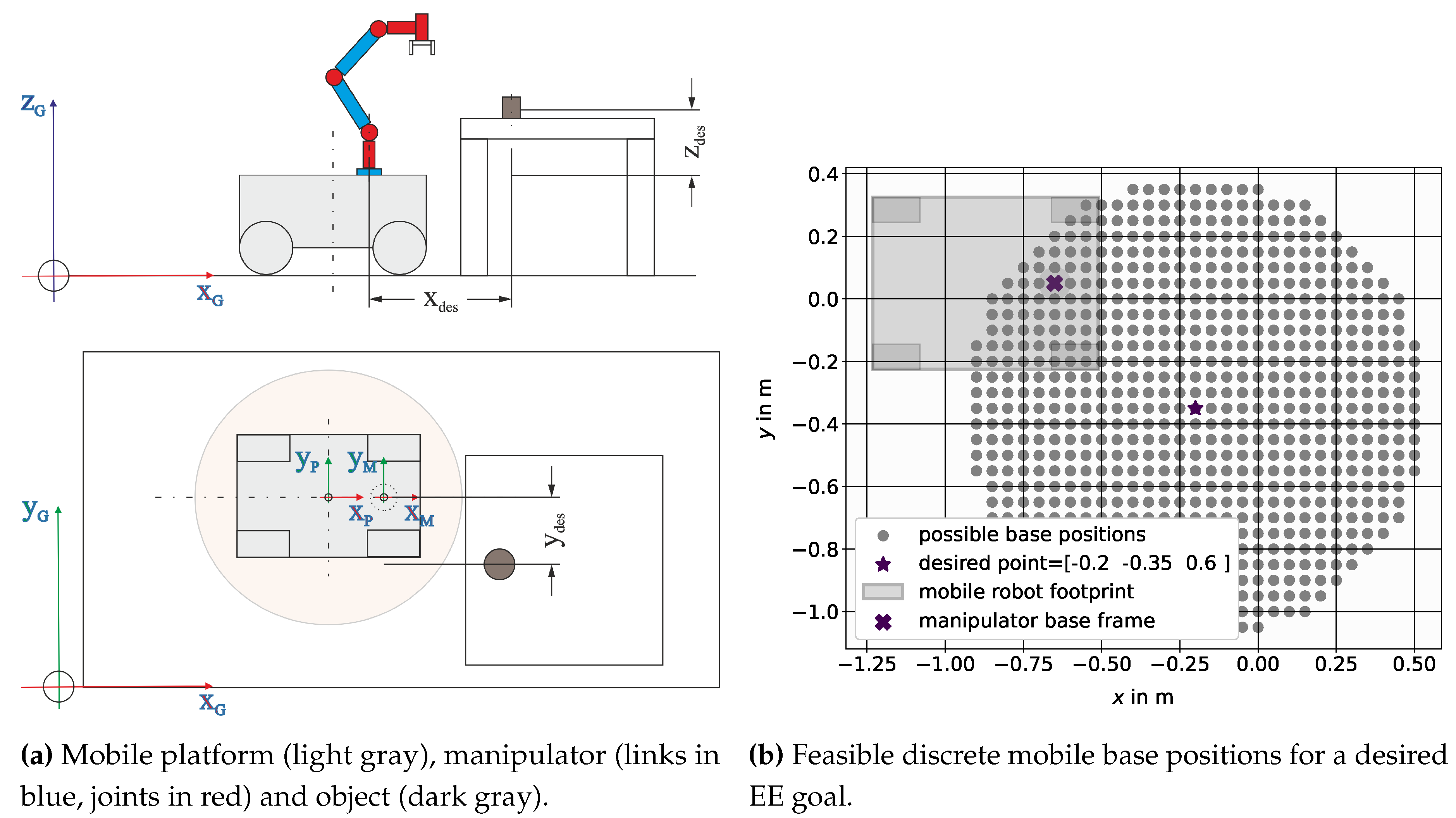
Figure 2a shows the principle of the task setup.
The pose of the object is described by the desired pose vector and will further on be used as the starting point to calculate the task dependent comfort zone for a suitable mobile base placement. Note that the calculation of the manipulability measures does not include the joints of the mobile platform , because excluding the platform joints allows to reserve this degree of freedom for navigation within the designated comfort zone and the orientation of the platform is often influenced by external factors, such as spatial constraints.
3.3. Recommended Workspace
While using a serial link structured robotic manipulator with rotational joints, the values for the minimal and maximal EE -coordinates,
and , are dependent of the desired z position. A subspace of the manipulators workspace where all positions and all orientations of the EE can be achieved is called recommended or dexterous workspace. To achieve all orientations of the EE, the desired position should be inside the recommended workspace of the robotic manipulator.
The workspace boundaries and workspace characterization of serial manipulators have been extensively researched [
7,
46,
47,
48]. Here, for simplification the outer limits of the recommended workspace for serial link manipulators are described by a triaxial ellipsoid as an approximation with
parameters a,b,c beeing the length of the three half axis which are specific to the used serial manipulator and the origin of the serial robot manipulator base frame is
Not reachable points within this simplified workspace are exclueded while calculating the proposed comfort zone.
By varying the
-positions of the mobile platform while holding the desired position of the EE fixed in the world frame, the configuration of the robotic manipulator can be changed. This set of configurations will be searched to find the comfort zone for the mobile manipulator. To find the inequality constraint equation for a point inside the recommended workspace, a plane is used to cut recommended workspace ellipsoid Eq. (
38) at point
with varying
-coordinates and a fixed
z-coordinate. Therefore, this plane in its normal form is
with
is said to be parallel to the (
)-plane and results in
Combining Eq. (
38) and Eq. (
41), an ellipse parallel to the
-plane, with its center at the point
and the axes lengths
can be found. Using the boundary condition
defined by the ellipse in Eq. (
42), a set of points
can be calculated. This set includes all points which can be reached by the EE while the mobile base is placed at the point
and can be defined as
Using the desired EE position
and all points
, a new set
of feasible base positions can be found. Assuming a planar movement in the
-plane of the mobile base and due to Eq. (
41),
is set to be zero and will further be neglected. Each element in the new set
represents a suitable position of the mobile base to ensure the desired EE position
using different manipulator joint configurations. By evaluation of the continuous set
with discrete values for
and
with
and
the discrete set
with
points can be found.
Figure 2b shows an exemplary set of
feasible positions for a mobile base with a mounted serial manipulator. The discrete set of points
is used to find a subset, defined as task dependent comfort zone (see Eq. (
54)) for mobile manipulator placement. Thereby different manipulability measures
, as described in the previous sections are used to evaluate the corresponding joint configuration for each point in the discrete set.
3.4. Manipulability Measure Norm, Combination, and Constrains
In order to obtain equal weighting of the different measures and to set suitable boundary conditions the measures are normed with the help of the minimum and maximum values out of a set of possible points
. The used manipulability measure
can be normalized into a range
using
with
is the maximum and
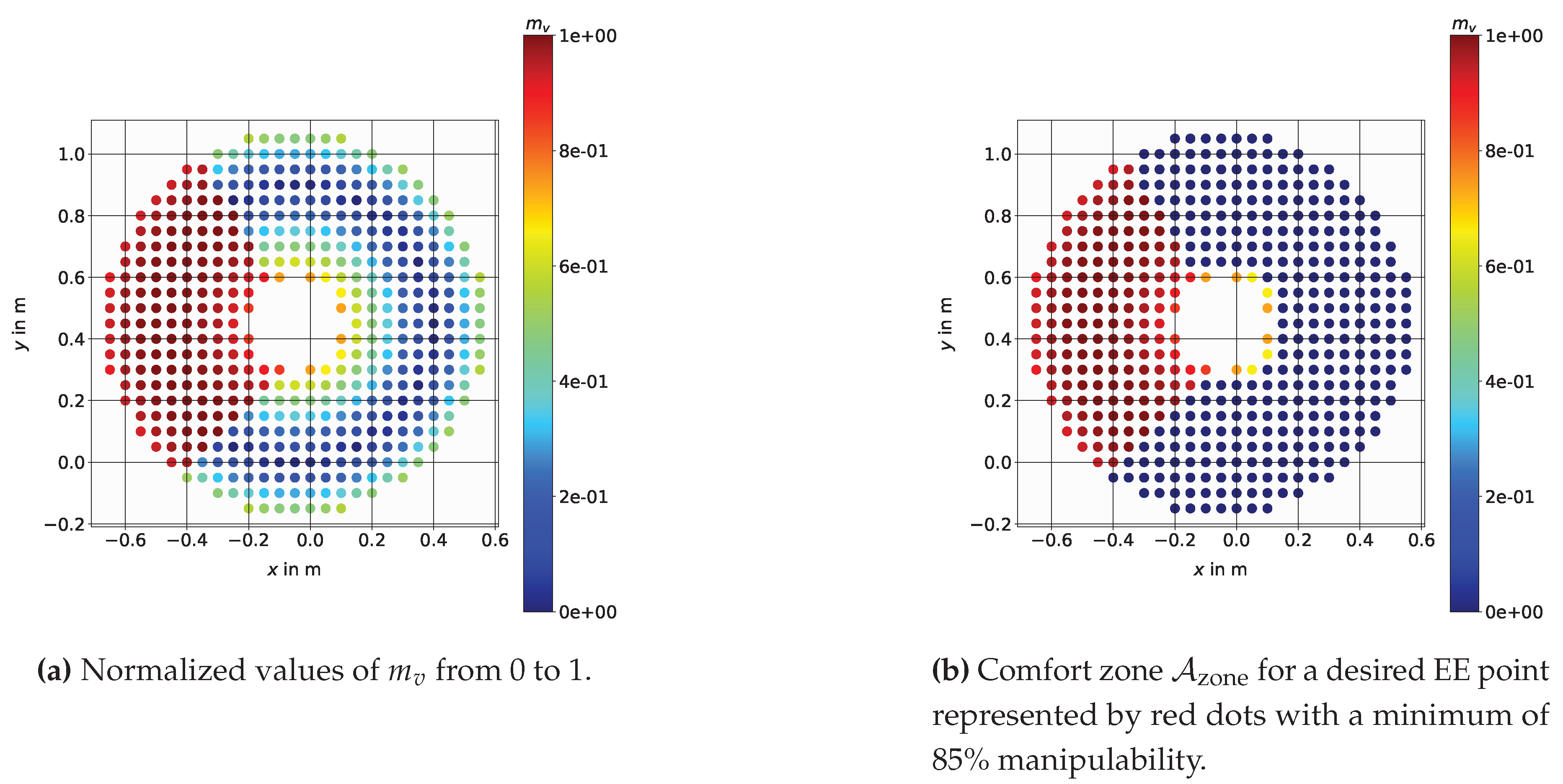
is the minimum value out of the given set of manipulability measures. This is shown by an example in
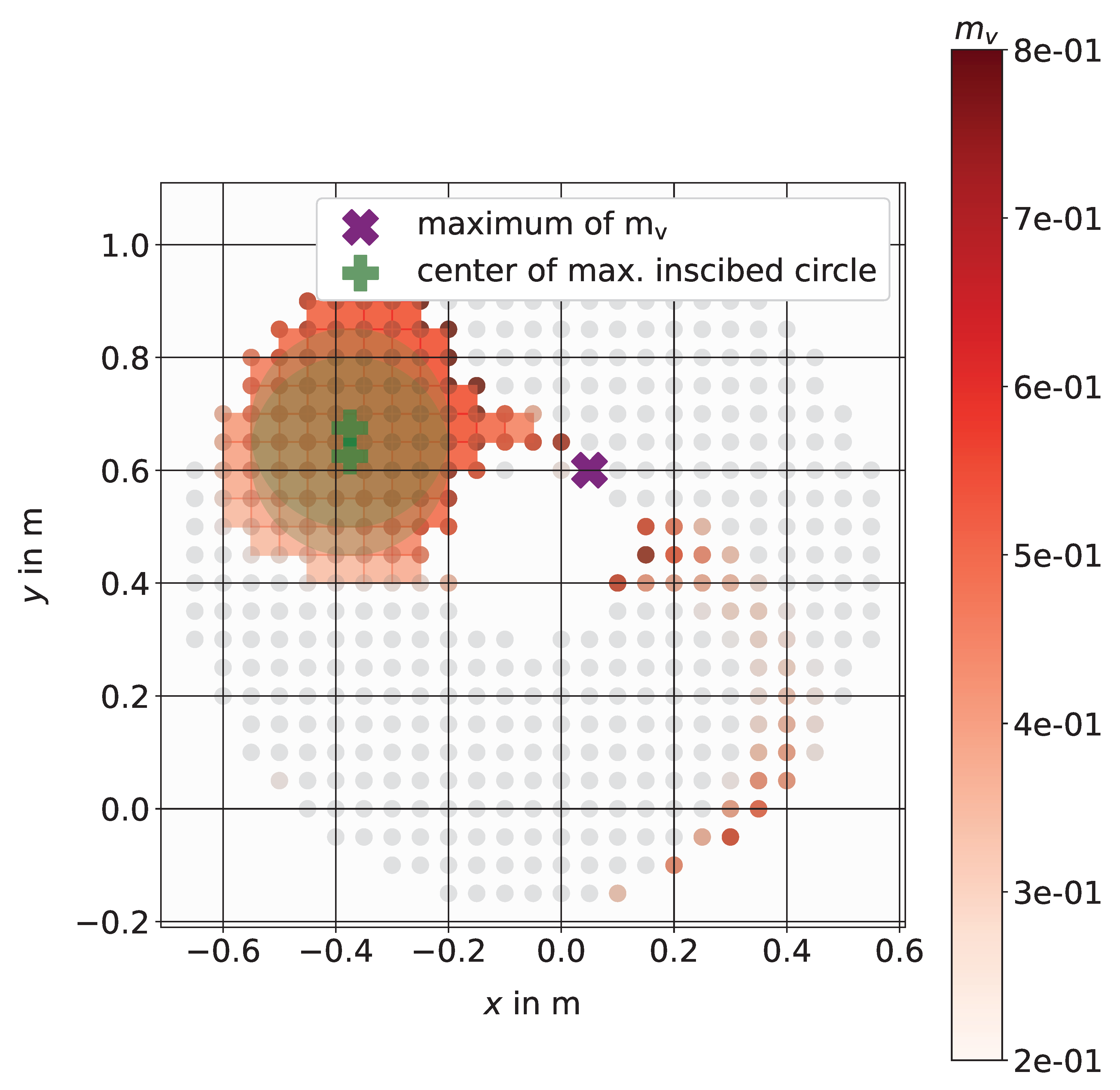
Figure 3a. Furthermore the measures can be combined using a weighted sum with
where
with
and
to maintain normalization.
3.5. Comfort Zone Definition
The discrete set of points
can be constrained into a feasible zone by using constraints for the manipulability measure
where
and
are the lower and upper constraints for each individual measure (
). By using these constraints, a zone of possible base positions can be defined. The defined task dependent comfort zone
for mobile manipulators with
includes all points
such that the corresponding joint configuration and its manipulability measure fulfills the set constraints as shown in
Figure 3b.
3.6. Comfort Zone Mesh Representation and Target Points
With the use of the discrete points defined by the comfort zone Eq. (
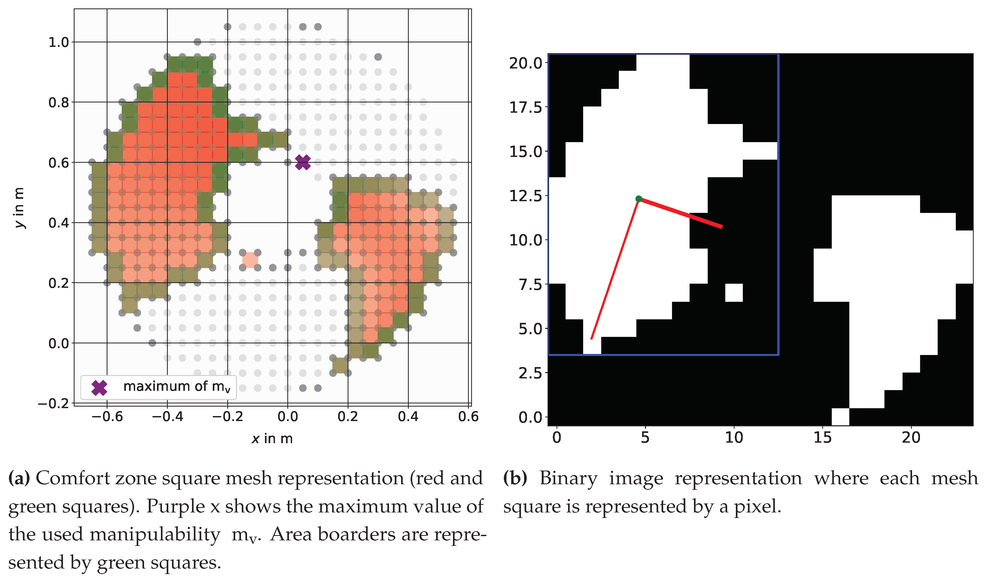
54) a square mesh as shown in
Figure 4a is built. For simplification and to avoid further computational effort with more precise discretization, the mean value out of 4 corner points for each square is used to interpolate the manipulability measure inside one square. We assume that in this square around each point no unfeasible solution in manipulator configuration will arise. The whole region is now used as a feasible goal for the mobile base.
Nevertheless, a defined point to aim for is needed and therefore we use the mesh representation and transform it into pixel coordinates where each square (center point) will be represented by an individual pixel. The resulting image, shown in
Figure 4b will then be used for further investigations with image processing algorithms from scikit-image
1, an image processing algorithm collection in Python [
49] and OpenCV
2, a library of Python bindings designed to solve computer vision problems. The following algorithms are used in three steps to determine a possible goal position inside the comfort zone: Firstly, the identification of possible disconnected areas by using the scikit-image function
label [
50]. Secondly, the comparison of the resulting areas with the scikit-image function
regionprops [
51] and, lastly, we use the OpenCV functions
distanceTransform [
52] and
minMaxLoc for finding the centerpoint and radius of the largest possible inscribed circle, see
Figure 5.
Figure 5 also shows that only the largest area found will be considered in further investigation. Therefore, other points which fulfill the manipulability constraints will be neglected even when the highest manipulability can be found outside the proposed comfort zone. Using the center of the largest possible inscribed circle in the comfort zone increases the robustness and enables to move around within this zone without a substantial loss of manipulability.
4. Comfort Zone Simulation Examples
We want to show the usage of the comfort zone for a given pick task and also that the approach can be applied to different types of mobile manipulators. All used mobile manipulators (the Stanford Robotics Platform, LeoBot, and Kairos) are equipped with a holonomic mobile base to achieve an omnidirectional movement. Each of these bases supports different types of serial manipulators. The results of this evaluation will provide insight into the practical usefulness of the proposed approach and its ability to offer specific guidelines for selecting appropriate base placements for different mobile manipulators. For the simulations a discrete workspace with a discretization of
and
, is used. The region of interest is a subdomain of the manipulators workspace. Therefore, a cuboid with
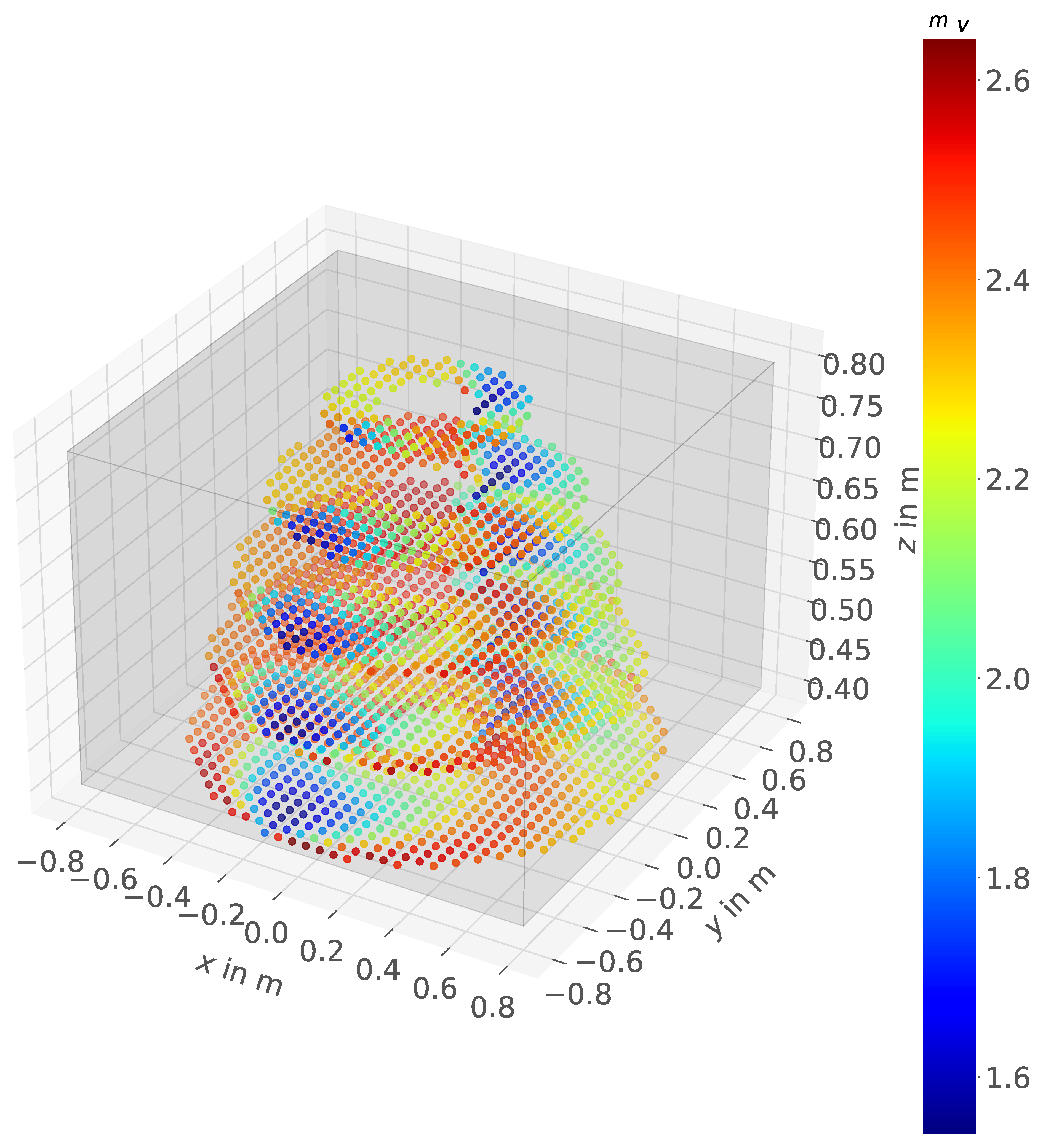
, as shown in
Figure 6, is used. The simulation examples are using either a desired EE pose
, or a desired EE position
where the orientation of the EE is not considered in the inverse kinematics calculation. For serial manipulators with a defined number of inverse kinematics solutions (UR5, PUMA) all feasible solutions (in terms of self-collision between manipulator and base) can be checked, for the Panda a numerical calculation of the inverse kinematics is used, so only one solution is checked. Also, within the shown results only either translational or rotational parts of the Jacobian matrix are considered while calculating the manipulability measures. Using the full Jacobian matrix would lead to problems as discussed in [
53]. Thereby the usage of the full Jacobian matrix has been shown to have no physical consistency due to the fact that the rotational and translational part have different physical units. All the simulations and calculations are done using Python and the flexible multibody systems framework Exudyn [
54]
3. In the simulation examples, the inverse kinematics algorithm
ikine_LMS according to Levenberg-Marquadt with Sugihara´s tweak [
55] from Peter Corke’s robotics toolbox [
56]
4 was used.
4.1. Stanford Robotics Platform
The Stanford Robotics Platform, is a mobile manipulator with a Puma560 mounted on a base using four so-called powered caster modules [
57]. In
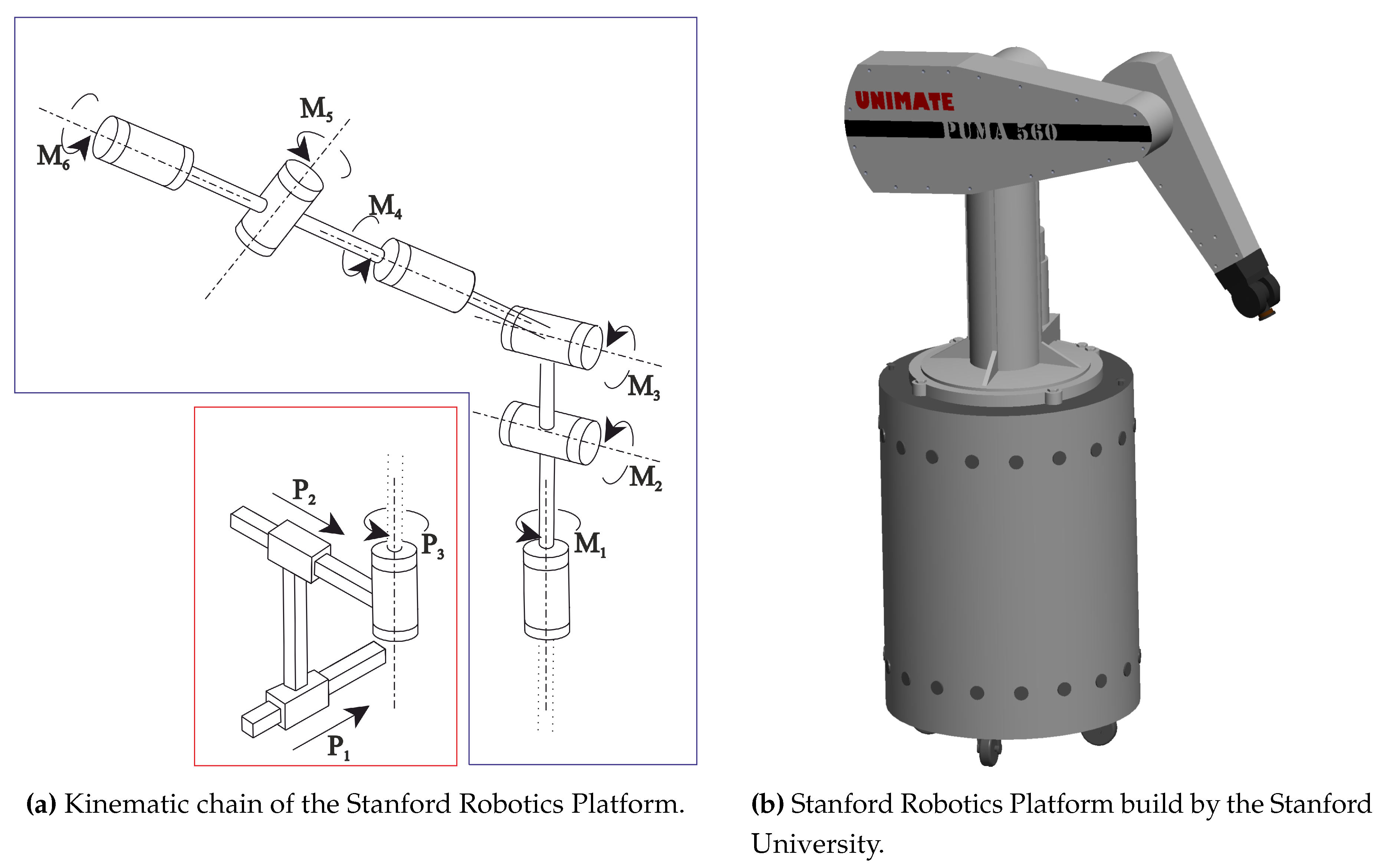
Figure 7b we show a 3D-CAD drawing as well as the kinematic chain. The Stanford Robotics Platformwas developed and built by the Stanford University Computer Science Department in year the 2000 [
58] and combines a Unimate Puma560 manipulator with 6 rotational joints and Euler wrist configuration mounted on a Nomadic XR4000 holonomic mobile base. The Puma560 manipulator is widely used in research as an example for a classic 6 DOF serial manipulator. The kinematic chain and its parameter are well described in the literature [
29,
59,
60]. The resulting system with 9 DOF is shown in
Figure 7a including the mobile platform joints
,
,
and the manipulator joints
to
.
In
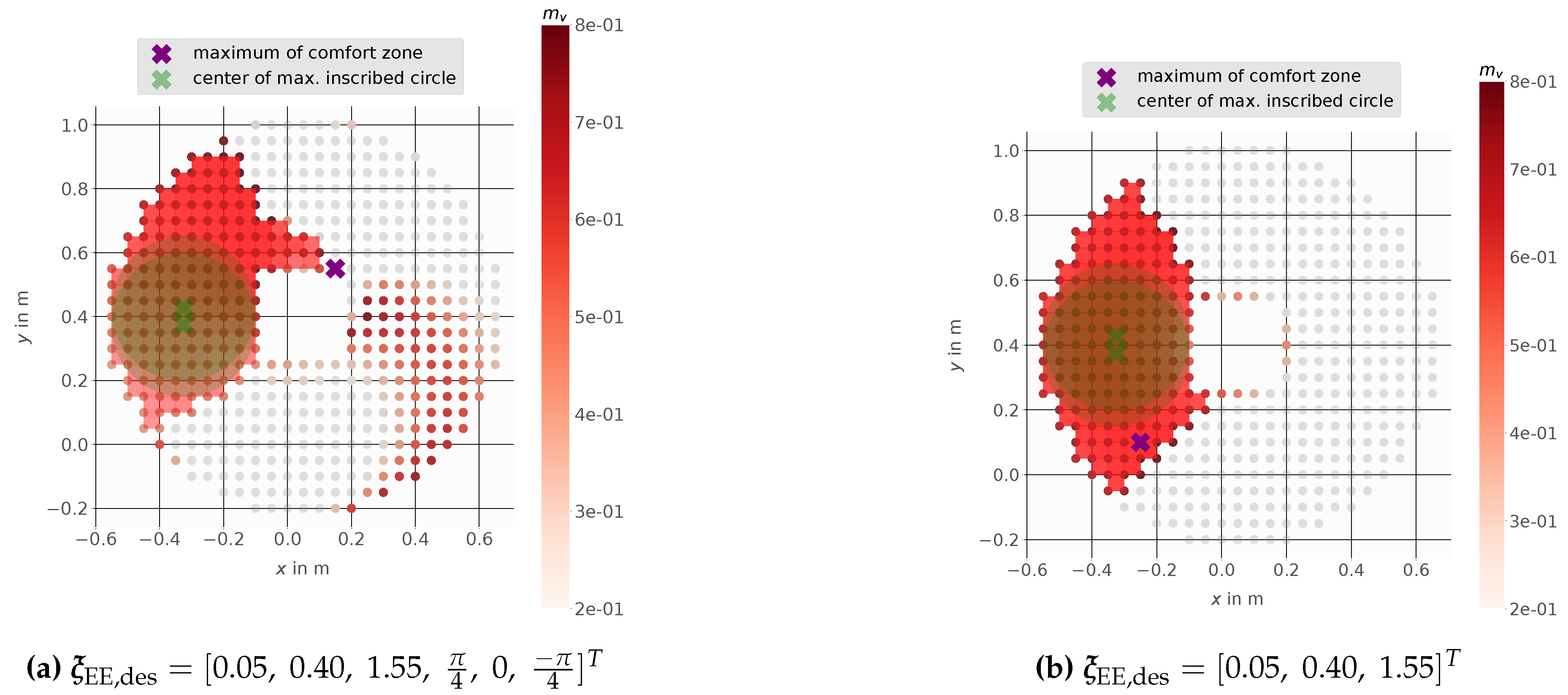
Figure 8 multiple possible placements for the mobile manipulator are shown. Both figures show the same results for pose and position while using the manipulability
where only linear velocities are considered.
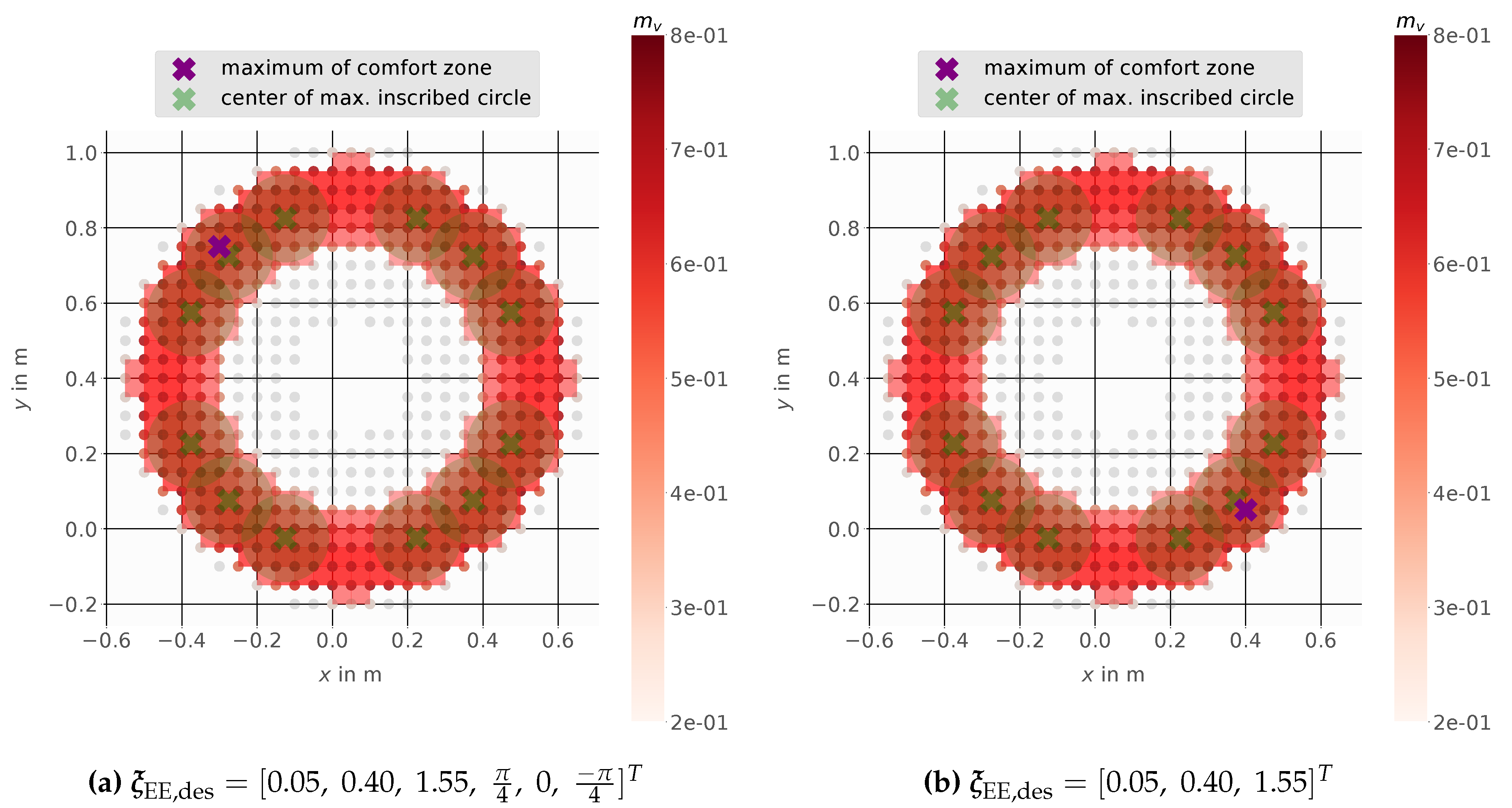
Figure 9 shows the results for
based on only angular velocities whereby especially in
Figure 9a the main purpose of the proposed comfort zone can be seen. Here the maximum value of the manipulability is outside the proposed comfort zone, therefore using this position leads to a lack of manipulability during operation for even a small movement of the mobile base. Using one of the proposed points (green), which are the centers of the maximum inscribed circles (light green), always leads to a manipulability of at least 65% of the maximum value.
4.2. Mobile Manipulator LeoBot
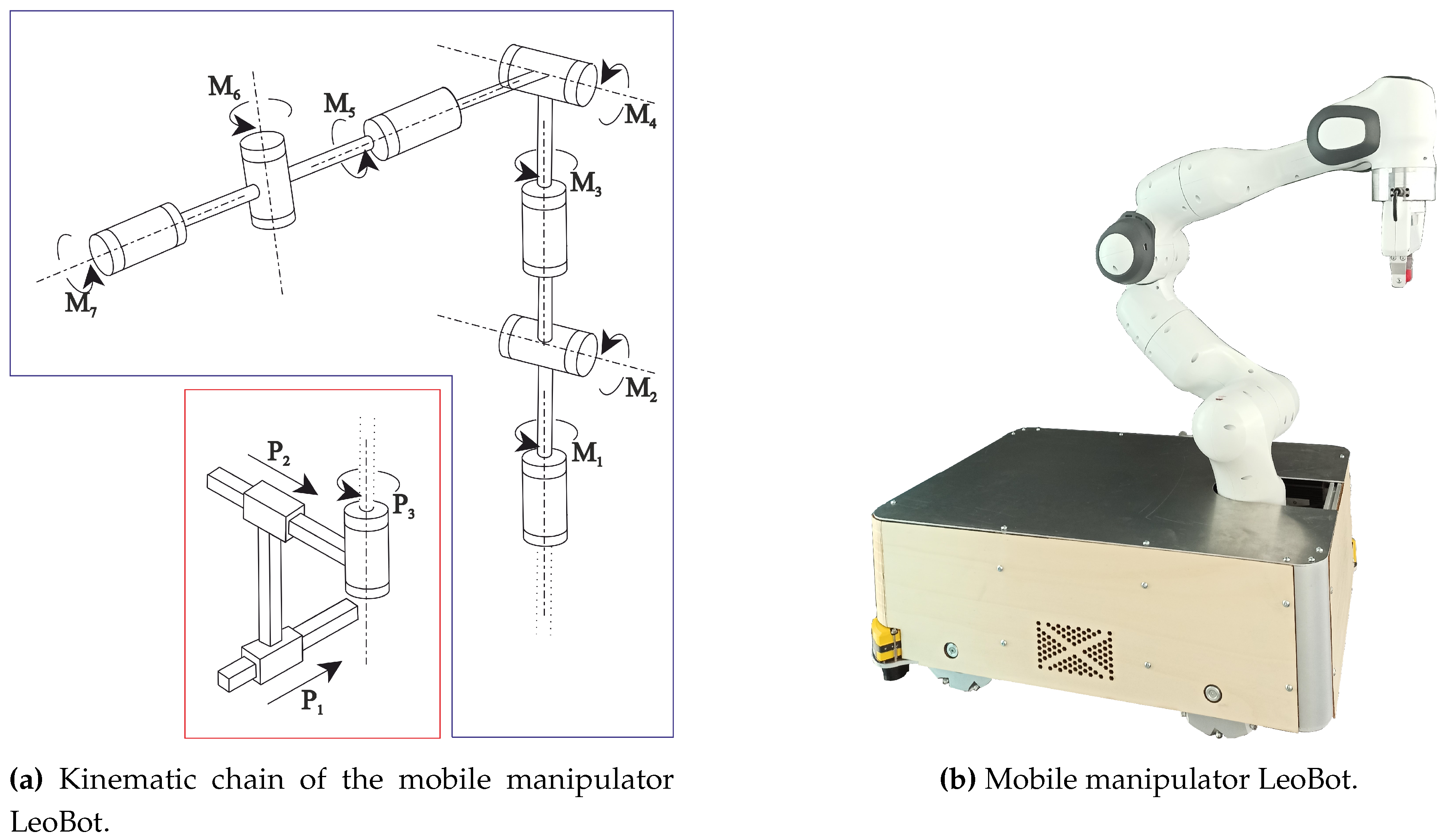
The mobile manipulator LeoBot [
61], shown in
Figure 10, uses Mecanum wheels for base motion with a mounted Franka Emika Panda 7 DOF serial manipulator.
Figure 10a shows the kinematic chain of LeoBot which achieves in total 10 DOF, including the mobile platform joints
,
,
and the manipulator joints
to
. The Franka Emika Panda is widely used in research and development and its parameters, including link masses, inertias and center of mass were recently investigated by researchers [
62].
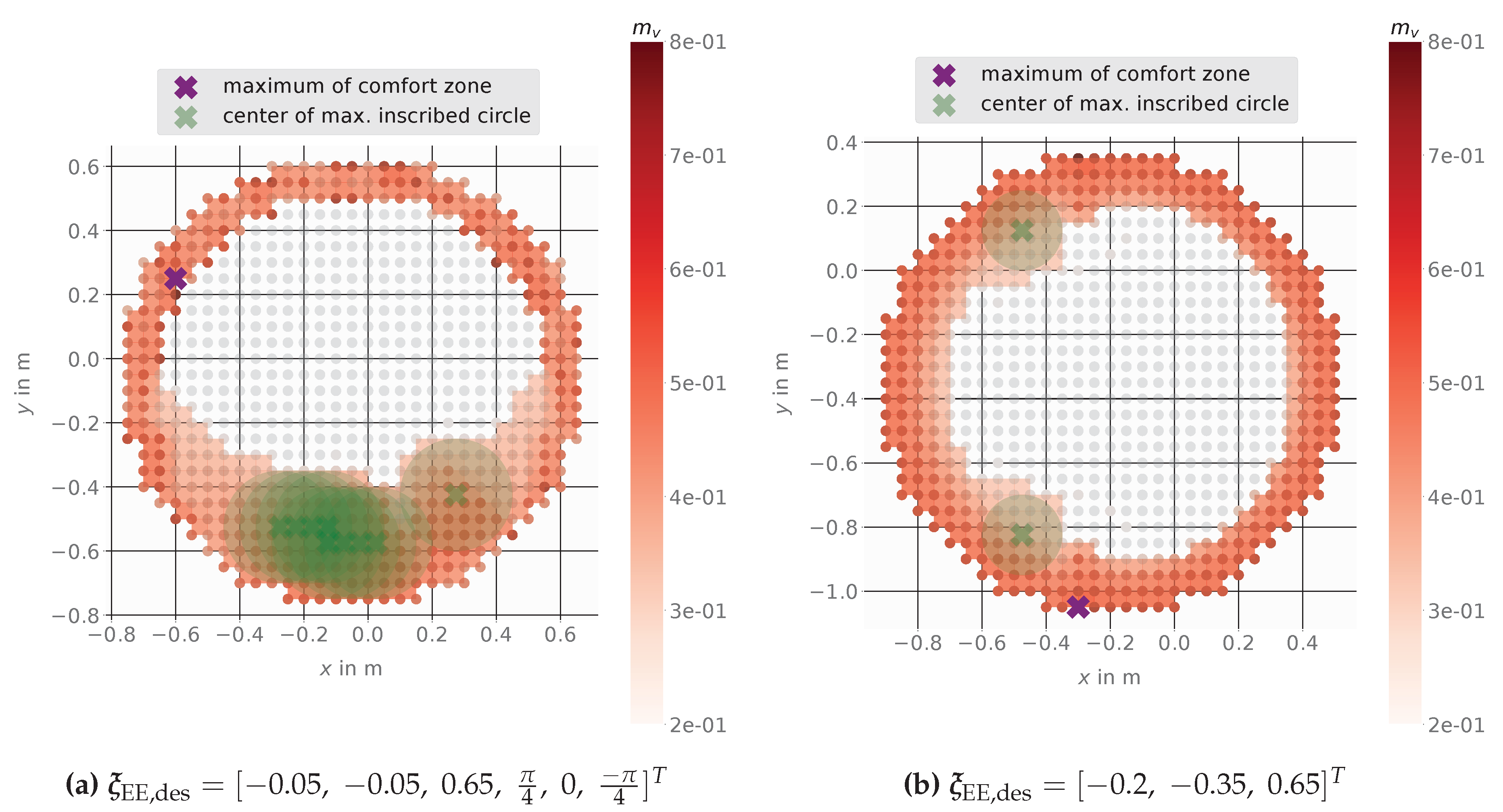
Figure 11 shows the results using
based on linear velocities.
Figure 11a shows that a mobile base placement at the proposed point (center of the maximal possible inscribed circle) gives the advantage to stay within a zone of minimum 30% manipulability even when the platform is moved. Also here the maximal manipulability is outside the comfort zone and a small movement there would lead to big loss in manipulability. The center points of all found inscribed circles would be feasible mobile platform goal positions with higher flexibility in base movement and ensures a solution for the inverse kinematics. A selection between them could be made by comparison of the individual manipulability of each point, but for all points here the manipulability is at least higher or equal than 30% of the maximum value.
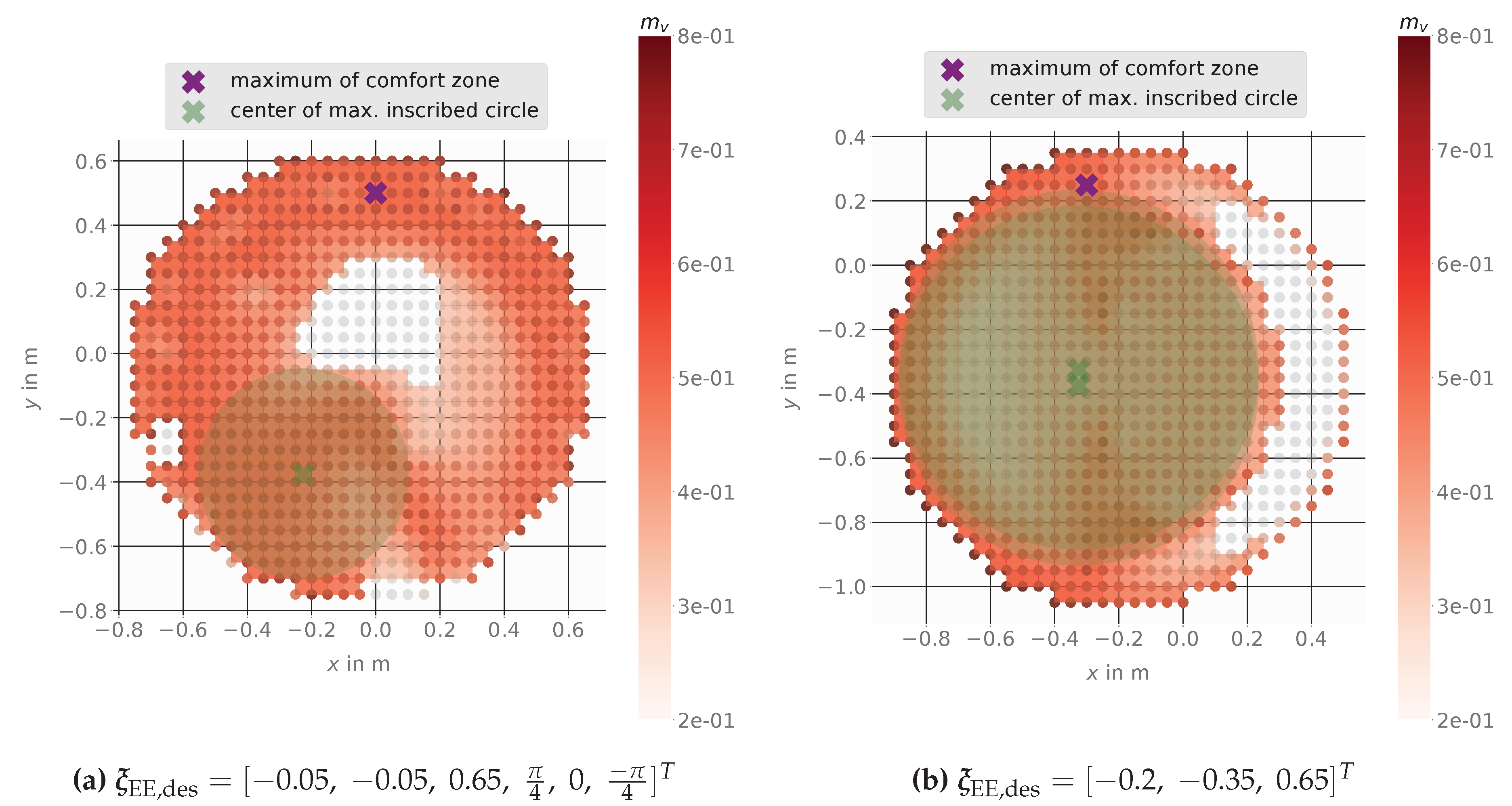
Figure 12 shows the results using
based on angular velocities. The mobile base placement at the proposed point (center of the maximal possible inscribed circle) gives a large zone of minimum 30% manipulability. The maximum value of manipulability is located outside of the comfort zone. So using that as a base goal position would quickly lead to a lack of manipulability.
4.3. Mobile Manipulator Kairos
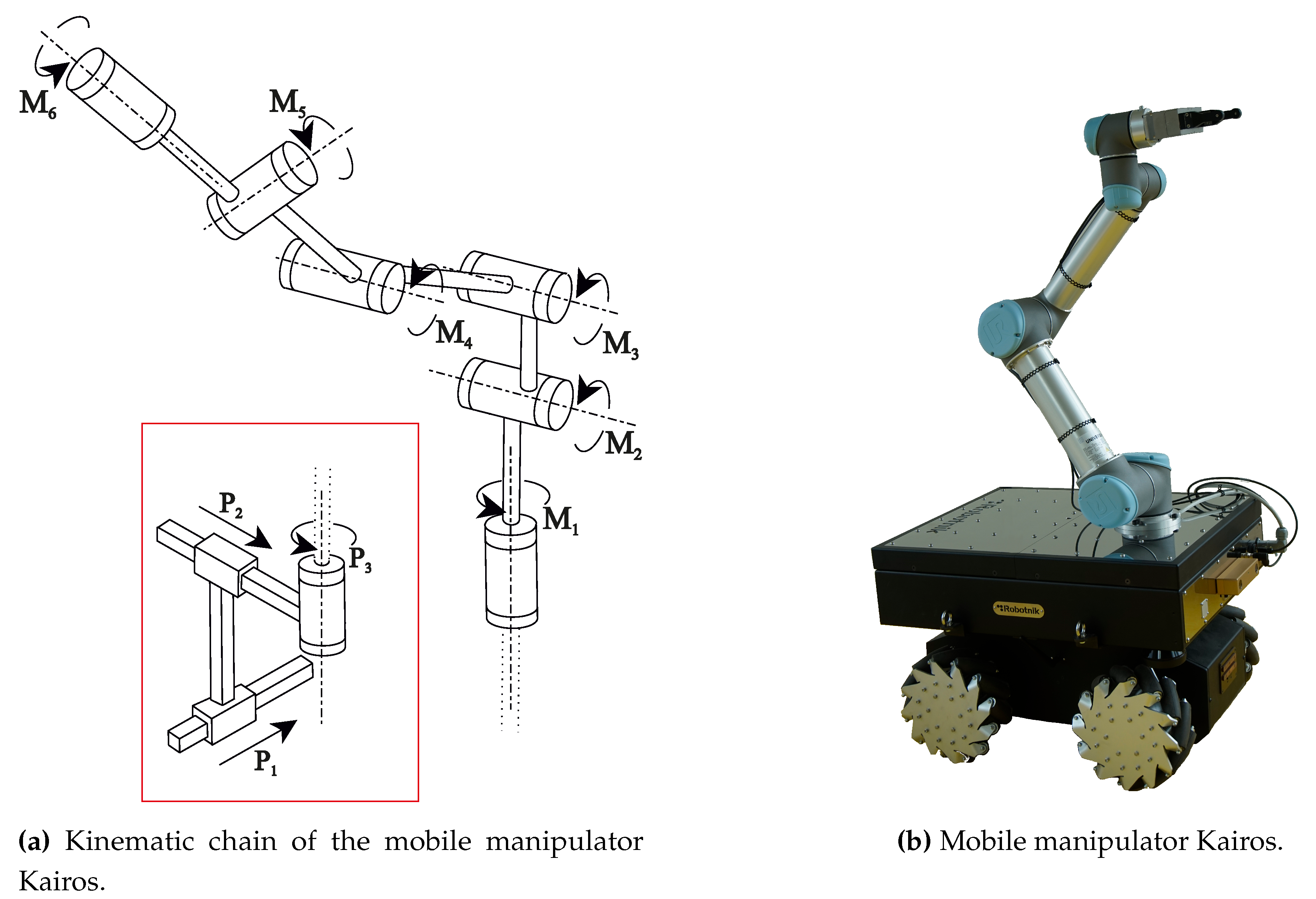
The mobile manipulator Kairos from the company Robotnik
5 combines a mobile base using Mecanum wheels with a mounted Universal Robot UR5 serial manipulator as shown in
Figure 13.
Figure 13a shows the kinematic chain of Kairos which achieves in total 9 DOF, including the mobile platform joints
,
,
and the manipulator joints
to
. The Universal Robot UR5 manipulator is often used in medium sized companies as well as in research and development. Its parameters including link inertias can be found in [
63,
64].
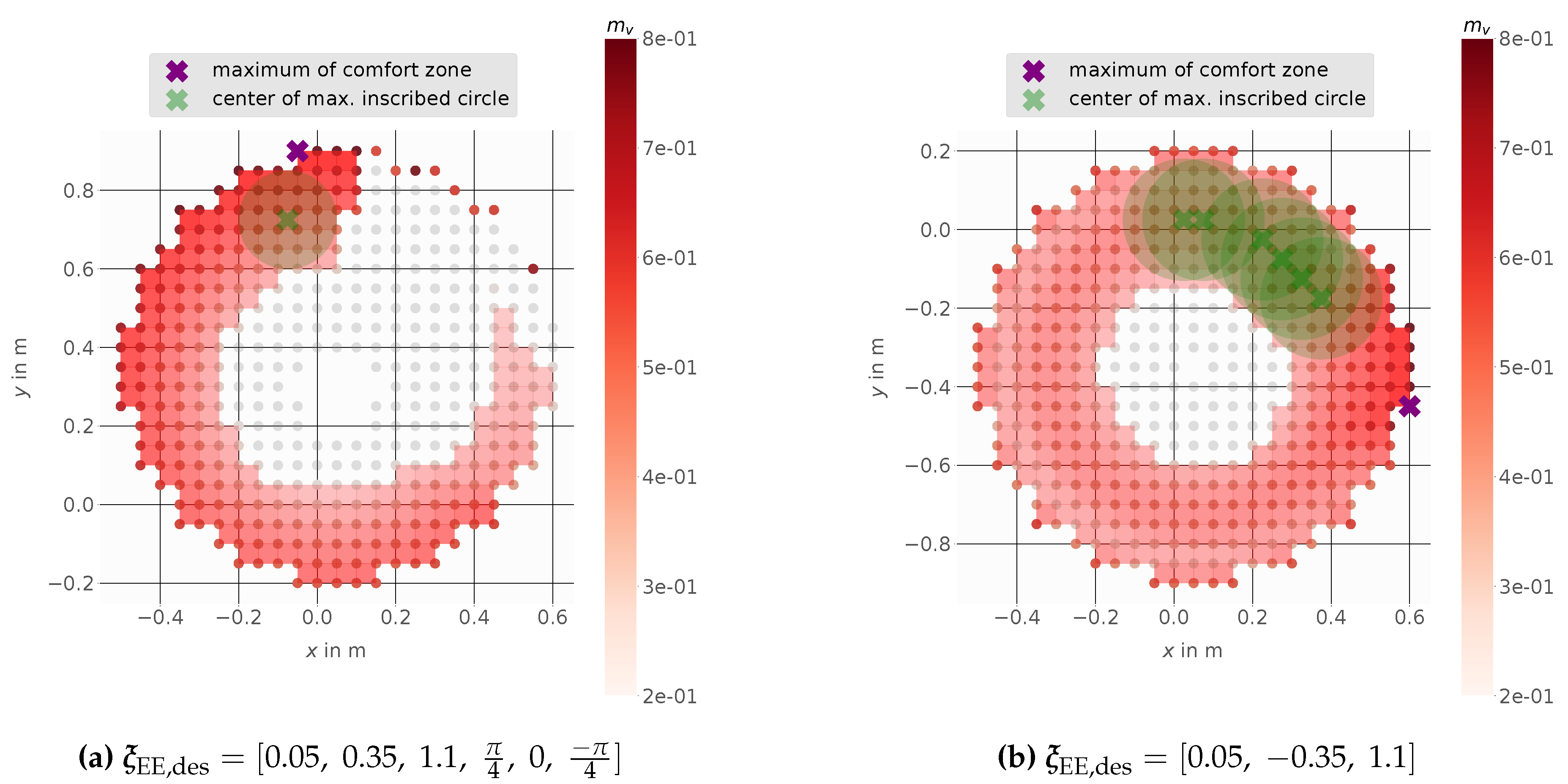
Figure 14 shows the results using
based on linear velocities.
Figure 14a shows that a mobile base placement at the proposed point (center of the maximal possible inscribed circle) gives the advantage of staying within a zone of minimum 30% manipulability, even when the platform is moved. The maximum value of the manipulability is located outside the comfort zone. Hence, using this position, already a small movement of the mobile platform would lead to a manipulability lower than 30% of the maximal value and the same is also valid for
Figure 14b.
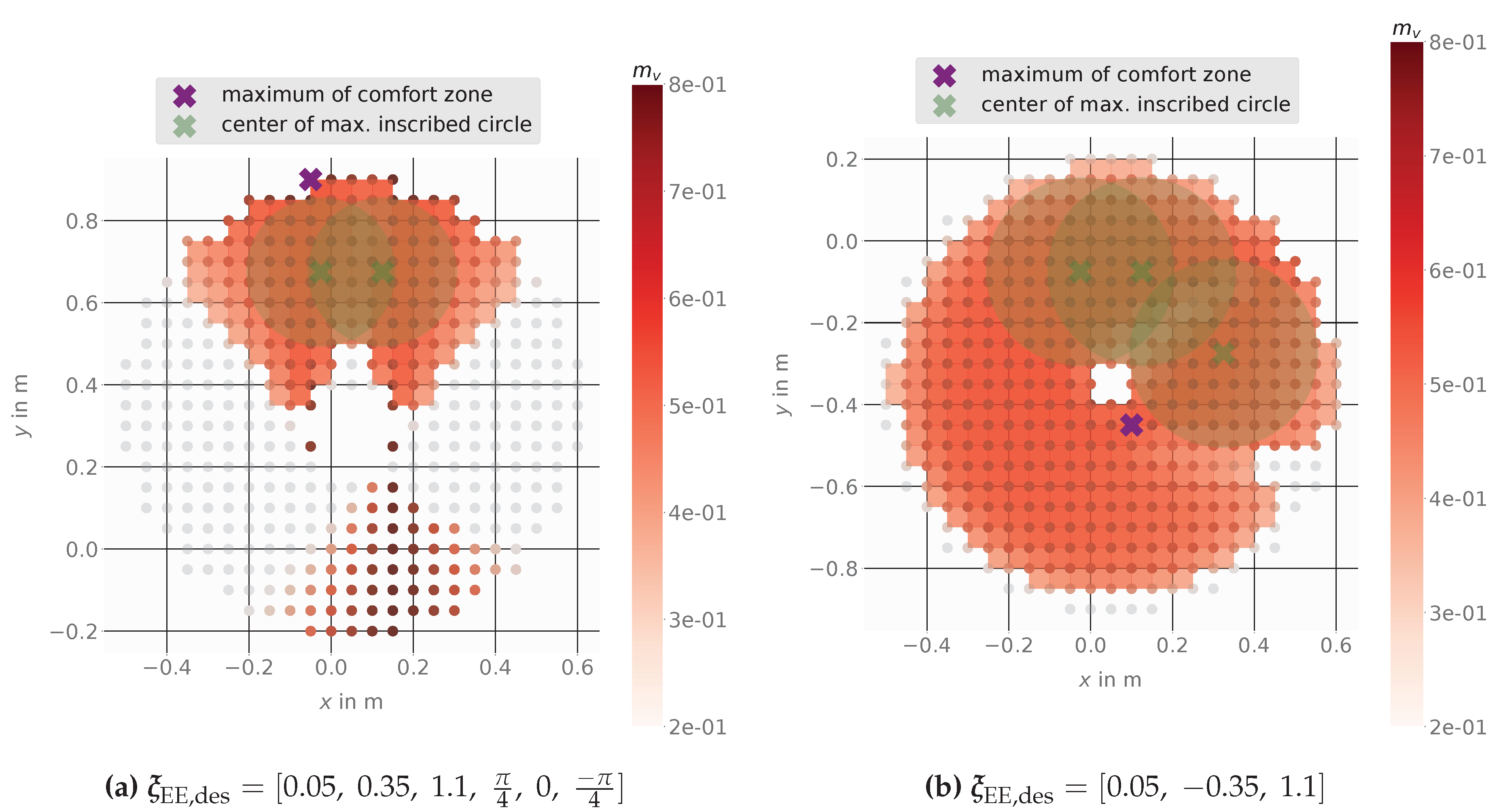
Figure 15 shows the results using
based on angular velocities. The mobile base placement at the proposed point (center of the maximal possible inscribed circle) gives a large zone of minimum 30% manipulability. In
Figure 15b the maximum value of manipulability is located near the middle of the comfort zone. Here, a small area is excluded from the comfort zone, so a base movement into this area could lead to failure of the task- as the inverse kinematics could not find a solution for this example. The center points of all inscribed circles would be feasible mobile platform goal positions with higher flexibility in base movement and ensures a solution for the inverse kinematics. A selection between them could be made by comparison of the individual manipulability of each point, but for all points here the manipulability is at least higher or equal than 30% of the maximum value.
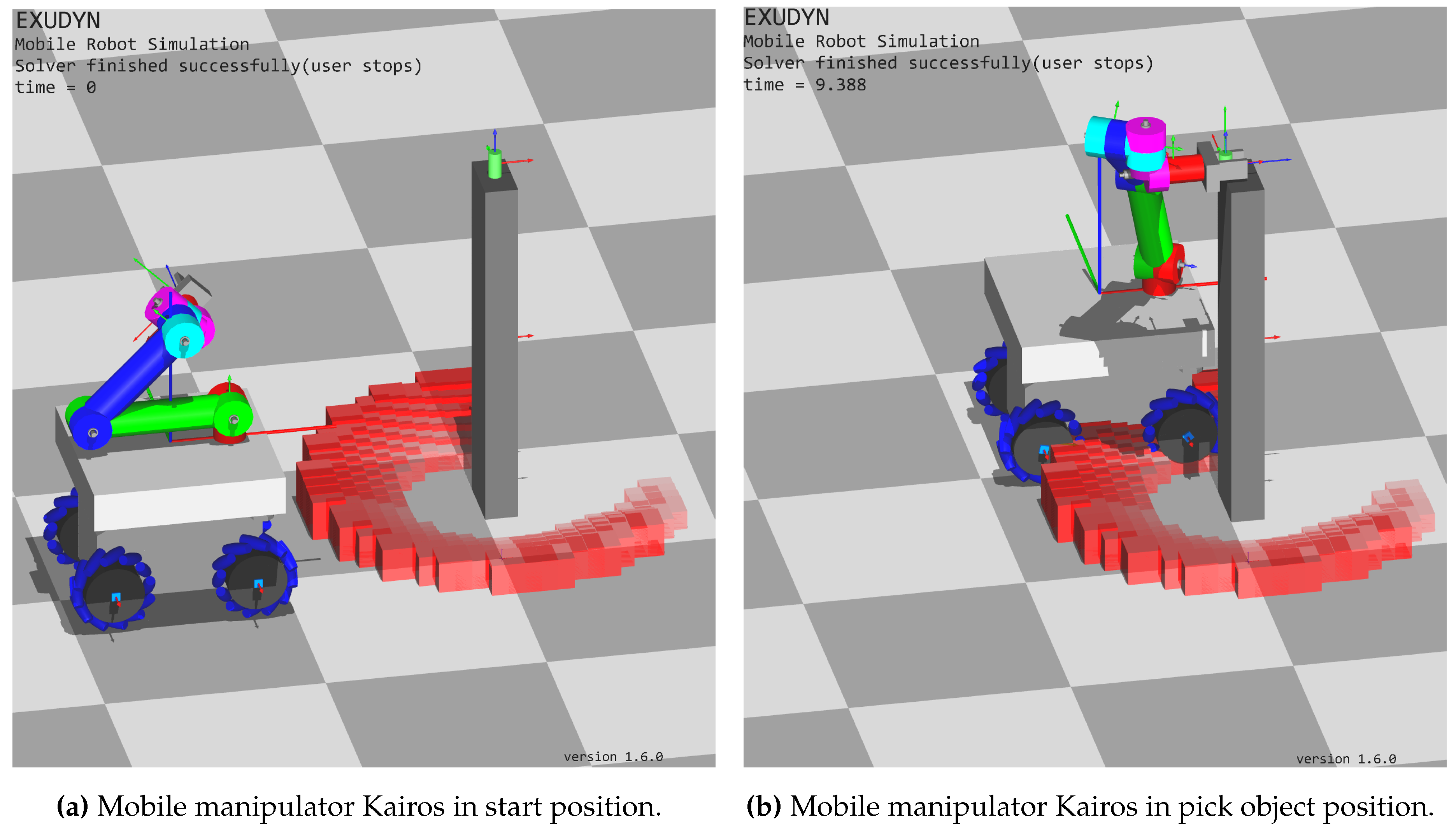
Figure 16 shows the mobile manipulator Kairos within a Python simulation. There, Exudyn (a C++ based Python framework for flexible multibody systems simulation) was used to simulate the mobile platform as well as the manipulator. The mobile platform and the manipulator links are represented by rigid bodies and the Mecanum wheels are modeled with a contact friction model based on the rolling disc as described in [
4]. In
Figure 16a the task starts and the comfort zone (possible mobile base goal placements) is drawn using red boxes. The height of each box corresponds to the used manipulability measure
.
Figure 16b shows the mobile manipulator within the pick task where the mobile base is already on its goal position.
5. Conclusions
In this work, we have presented a method to determine a zone of possible base positions, the so-called task dependent comfort zone, for mobile manipulators based on different manipulability measures. Our method takes into account the specific demands of different tasks, such as the need for high-speed movements, large forces, high accelerations, or heightened stiffness. To find a suitable goal position for a mobile manipulator we used discretization of the manipulator workspace and different image processing methods.
We evaluated our method in Python computation using different holonomic mobile manipulators. First, we used the Stanford Robotics Platform with a mounted Puma560 (6DOF, spherical wrist). Secondly, we used the mobile manipulator LeoBot with a mounted Franka Emika Panda (7DOF), and lastly, the mobile manipulator Kairos with a mounted Universal Robot UR5 (6DOF).
Our results showed that manipulability measures could be used to develop a task-dependent comfort zone for mobile manipulators, providing more specific guidelines for selecting appropriate mobile manipulator base placement strategies. In path planning algorithms, a fixed goal position for the mobile base is usually given, although in many cases the exact positioning of the platform is not as important as the goal of the manipulators end-effector.
Once, the
task dependent comfort zone is calculated, it can help to find feasible mobile manipulator base positions in dynamically changing environments. Our study highlights the importance of considering manipulability measures when determining mobile manipulator base positions and shows the potential of our proposed method for use in practical applications. Future work could explore the use of our method within real-world scenarios to further evaluate its effectiveness. Thereby combining the concept of the task dependent comfort zone with a path planning algorithm to use it within the robot framework ROS should be considered. Especially a combination with the
costmap2D algorithm [
65] used in the ROS-Navigation stack. With help of this algorithm the proposed task dependent comfort zone could be included as an additional cost map layer to the ROS-Navigation stack [
66].
Figure 1.
Geometrical representation of four different manipulability measures using a planar mobile manipulator with 5DOF.
Figure 1.
Geometrical representation of four different manipulability measures using a planar mobile manipulator with 5DOF.
Figure 2.
Schematic overview for a pick and place task (a). Feasible discrete base positions of a mobile manipulator (b).
Figure 2.
Schematic overview for a pick and place task (a). Feasible discrete base positions of a mobile manipulator (b).
Figure 3.
Discrete point plot representation of feasible base position points for the Stanford Robotics Platform. Quality of points described by manipulability measure , red points have a high manipulability. Manipulability measure is dependent on the angular velocity of the EE for a desired EE pose .
Figure 4.
Comfort zone example for the Stanford mobile manipulator, transformation to pixel representation. Each red/green square in (a) is transformed to a white pixel in (b) and represents a suitable mobile base position for the desired EE goal.
Figure 4.
Comfort zone example for the Stanford mobile manipulator, transformation to pixel representation. Each red/green square in (a) is transformed to a white pixel in (b) and represents a suitable mobile base position for the desired EE goal.
Figure 5.
Comfort zone square mesh representation. Green circle represents the largest possible inscribed circle in the comfort zone with its center point marked in green. The maximum value of the used manipulability is marked in purple. Each red square represents a suitable mobile base position for the desired EE goal at with at least 85% of the maximum manipulability.
Figure 6.
Discrete subdomain of the Puma560 manipulator workspace shown as a grey cuboid. Evaluation of all discrete points regarding their manipulability (not normalized, ).
Figure 6.
Discrete subdomain of the Puma560 manipulator workspace shown as a grey cuboid. Evaluation of all discrete points regarding their manipulability (not normalized, ).
Figure 7.
Serial manipulator with 6 rotational joints mounted on a Nomadic XR4000 holonomic mobile base.
Figure 7.
Serial manipulator with 6 rotational joints mounted on a Nomadic XR4000 holonomic mobile base.
Figure 8.
Comfort zone for the Stanford Robotics Platform using the linear velocity dependent manipulability measure with a minimum of 65% manipulability for EE pose (a) and EE position (b).
Figure 8.
Comfort zone for the Stanford Robotics Platform using the linear velocity dependent manipulability measure with a minimum of 65% manipulability for EE pose (a) and EE position (b).
Figure 9.
Comfort zone for the Stanford Robotics Platform using the angular velocity dependent manipulability measure with a minimum of 65% manipulability for EE pose (a) and EE position (b).
Figure 9.
Comfort zone for the Stanford Robotics Platform using the angular velocity dependent manipulability measure with a minimum of 65% manipulability for EE pose (a) and EE position (b).
Figure 10.
LeoBot mobile manipulator developed and built by the Department of Mechatronics at the University of Innsbruck in year 2020. The mobile manipulator combines a Franka-Emika-Panda manipulator with 7 rotational joints mounted on a holonomic mobile base using Mecanum wheels.
Figure 10.
LeoBot mobile manipulator developed and built by the Department of Mechatronics at the University of Innsbruck in year 2020. The mobile manipulator combines a Franka-Emika-Panda manipulator with 7 rotational joints mounted on a holonomic mobile base using Mecanum wheels.
Figure 11.
Comfort Zone for the mobile manipulator LeoBot using the linear velocity dependent manipulability measure with a minimum of 30% manipulability for EE pose (left) and EE position (right).
Figure 11.
Comfort Zone for the mobile manipulator LeoBot using the linear velocity dependent manipulability measure with a minimum of 30% manipulability for EE pose (left) and EE position (right).
Figure 12.
Comfort Zone for the mobile manipulator LeoBot using the angular velocity dependent manipulability measure with a minimum of 30% manipulability for EE pose (a) and EE position (b).
Figure 12.
Comfort Zone for the mobile manipulator LeoBot using the angular velocity dependent manipulability measure with a minimum of 30% manipulability for EE pose (a) and EE position (b).
Figure 13.
Mobile manipulator Kairos developed and built by the company Robotnik. The mobile manipulator combines an Universal Robot UR5 manipulator with 6 rotational joints mounted on a holonomic mobile base using Mecanum wheels.
Figure 13.
Mobile manipulator Kairos developed and built by the company Robotnik. The mobile manipulator combines an Universal Robot UR5 manipulator with 6 rotational joints mounted on a holonomic mobile base using Mecanum wheels.
Figure 14.
Comfort Zone for the mobile manipulator Kairos using the linear velocity dependent manipulability measure with a minimum of 30% manipulability for EE pose (a) and EE position (b).
Figure 14.
Comfort Zone for the mobile manipulator Kairos using the linear velocity dependent manipulability measure with a minimum of 30% manipulability for EE pose (a) and EE position (b).
Figure 15.
Comfort Zone for the mobile manipulator Kairos using the angular velocity dependent manipulability measure with a minimum of 30% manipulability for EE pose (left) and EE position (right).
Figure 15.
Comfort Zone for the mobile manipulator Kairos using the angular velocity dependent manipulability measure with a minimum of 30% manipulability for EE pose (left) and EE position (right).
Figure 16.
Mobile manipulator Kairos approaching a target object by using the task dependent comfort zone (red boxes) for mobile manipulator base placement. Values as shown in
Figure 14.
Figure 16.
Mobile manipulator Kairos approaching a target object by using the task dependent comfort zone (red boxes) for mobile manipulator base placement. Values as shown in
Figure 14.
Table 1.
Summery of used manipulability measures.
Table 1.
Summery of used manipulability measures.
| Symbol |
Formula |
Description |
|
Eq. (13) |
Proportional to the volume of the EE velocity ellipsoid, which represents the ability to move the EE with a certain velocity in all directions. |
|
Eq. (17) |
Proportional to the volume of the EE force ellipsoid, which represents the ability to act with a certain force in all directions. |
|
Eq. (26) |
Represents the minimum eigenvalue of the Cartesian stiffness matrix, which characterizes the smallest stiffness in a certain configuration. |
|
Eq. (34) |
Represents the minimum eigenvalue of the weighted dynamic manipulability matrix, which characterizes the smallest acceleration in a certain direction. |
Table 2.
Possible classification of robotic tasks
Table 2.
Possible classification of robotic tasks
| Task Type |
Velocity |
Force |
Stiffness |
Acceleration |
| Pick and Place |
High |
Moderate |
Low |
High |
| Assembly |
Moderate |
High |
High |
Moderate |
| Painting |
Moderate |
Low |
Low |
Low |
| Milling |
Low |
High |
High |
Low |
