
Submitted:
06 July 2024
Posted:
08 July 2024
You are already at the latest version
Abstract
Nano surface finishing can be achieved from the recently developed electrophoretic deposition-assisted polishing (EPDAP) process. This state-of-art work presents a comparison of the effect of surface roughness and material removal rate on the grit size, axial load, rotational speed, polishing time, etc. for SS304, SS316L and alumina ceramics. The EPDAP process can assess the surface's characteristics' quantity, and quality on different materials which have been tried on SS316L, SS304, inner bore of SS304, and Al2O3 in our laboratory. Uniform dispersion of homogeneous micro-sized abrasive grains was accomplished by electrophoretic deposition (EPD) to create the polishing tool employed in this process. Polishing time, axial loading, grit size, and speed of rotation of the polishing tool was selected as the control parameters. The polishing tool undergoes erosion of blunt-edged-abrasive grains due to abrasion during the EPDAP process. Therefore, the polishing tool was continuously revitalized by adding fresh abrasives. The analysis of the experiments is conducted using ANOVA and the evolutionary algorithm teaching-learning method. EPDAP process revealed improved surface reflection as well as improvement in surface finish. Thus, optimization of the polishing parameters was conducted for the experiments. The surface roughness achieved from the experiments is 0.04557 microns for SS316L, 0.038 microns for SS304, and 0.404 microns for Al2O3. Therefore, 93.92%, 97.64 %, and 73.75 % of improvement in the surface finish were achieved in SS316L, SS304, and Al2O3, respectively.
Keywords:
Electrophoretic deposition
; Percentage reduction in surface roughness
; polishing
1. Introduction
Polishing is one of the processes producing a fine finish. For ages, smooth and shiny surfaces have been man’s fantasy; man has always tried to achieve such surface finish. One step to achieving this finish is the development of the polishing process. Although polishing has not only found its application in aesthetics, but these processes have also seen significant applications in engineering. The machine’s operating efficiency can be improved by generating smooth surfaces to reduce friction between the mating components subjected to relative motion. The generation of smooth surfaces is no longer a complete application in the engineering domain. Another field developing these days rapidly is the field of biomedical engineering. The development of prosthetic joints and parts demands similar traits as that of original bones. The replacement of bones made of calcium with stainless steel components requires a superior surface finish, preventing corrosion and contamination of the human body’s cells and the prosthetic part, giving it a longer life. Thus bio-medical has increasing applications in the super finishing processes [1,2,3,4,5,6,7,8,9].
1.1. Fundamentals of the Polishing Process
Primary manufacturing processes are employed to shape the geometry and dimensions of the part, while secondary manufacturing processes are used for obtaining a superior surface quality, tolerance, and integrity [10,11]. One of the critical secondary manufacturing processes is polishing, which significantly improves the surface finish and integrity [10,12,13,14,15].
EPDAP is an ultra-precision/ultrafine polishing process, as presented in Supplementary Figure S1, that can produce nano-finished surfaces (10-60 nm). This method is suitable for hard and brittle materials [12,16,17]. It can be used for polishing conducting and non-conducting materials, including stainless steel, ceramic, and silicon wafer components for MEMS. It is an electrochemical process based on electrophoresis and the electro-osmosis phenomenon. In the case of electrophoresis, when the oxide particles are added to water, it carries an electric charge in water, viz. When added to water, silica particles move a high negative charge. The negatively charged colloidal silica generates repulsive force towards the dispersion of the ultrafine silica particles, which have diameters less than 100 nm. To achieve a mirror, the finish of the surface, polishing agents like silica colloids are traditionally utilized due to the activation of high electric charge in the presence of chemical action. The application of an electric field achieves the movement of silica particles towards the anode to the solution due to the attractive forces generated between them. On the other hand, in electro-osmosis, the finished surface is vulnerable to the accumulation of silica particles which cause roughness and surface deterioration due to the blunt edges of the silica particles. Electro-osmosis is a by-product of electrophoresis. For electro-osmosis, the discharge of the liquid in the solid is in the reverse direction compared to electrophoresis. Hence, the liquid within the deposited layer of silicon particles is eliminated, and the adhered layer is withered away by developing cracks on the surface [18,19,20,21,22,23].
The particulate matter is formed on the electrode with the help of the Electrophoretic deposition (EPD) process. Electrophoretic deposition is a process in which the solvent acts as a dispersion medium for the desired particles of which the electrode is to be generated. The movement and deposition of these particles are achieved by applying an electric field to the solvent. The attributes of the EPD process in this study are as follows:
- Dispersion and independent movement of dispersed particles within the solvent medium.
- Electrochemical equilibrium of the particles with the solvent leads to the realization of surface charge on the particles.
- Motion of the particles suspended in bulk occurs due to electrophoresis.
- A layer of finite shear strength rigid layer of particles is deposited on the electrode.
The development of advanced mechanical polishing methods like abrasive polishing, Ultrasonic polishing, and magneto-elastic fluid-assisted polishing has demonstrated limited success, where the particle’s kinetic energy is used for the material removal mechanism where small quantities of material are ablated from the surface. In our previous work, we developed abrasive polishing which uses the kinetic energy of abrasive particles flowing along with the slurry [24]. Since the particles come in direct contact with the workpiece, these polishing techniques are limited by the workpiece’s hardness, strength, and other physical and mechanical properties. To successfully polish materials like High Entropy alloys, High strength temperature resistant (HSTR) alloys, Haste Alloy, etc., it is necessary that the machining process interdependent on the metallurgical, mechanical, and physical properties of the workpiece [25]. Hence, depositions-assisted superior performance as they overcome the barriers posed by the mechanical methods dependent on the ablation mechanism.
In thermoelectric methods, heat generated by plasma, laser, and electron bombardment provides the energy for the material removal mechanism. The concentration of the energy source confined to a small area of the workpiece material leads to small quantities of melting or vaporization or both of the workpiece. Laser and electron-based ablation methods can produce a very superior surface finish. However, the mechanical and thermoelectrical methods do not offer a satisfactory solution to some of the problems of polishing difficult to machine materials.
EPD is a recent deposition-based polishing technique that can develop a nanometric surface finish. This process ensues in two phases. Initially, an electric field is applied to the solvent, consisting of dispersed abrasive elements, due to which motion of the particles towards the electrodes is achieved. In the next phase, the deposited particles on the electrode are strongly bonded by eliminating liquid/moisture content from the adhered layer [26,27,28,29,30,31,32]. Hence EPD can develop a thick and thin coating layer on the electrodes [33,34]. The suspended silicon oxide particle produces an electric charge due to maintaining electrochemical equilibrium with the solvent. The charges developed on the particles assist in their motion toward the electrode by applying a DC electric field. The addition of surfactants and charged polymers in the solvent leads to having high electrostatic stability of the suspended particles in the solvent. The abrasive particles act as anions and migrate towards the negative charge anode on the application of electromagnetic field; hence, deposition occurs called EPD. Electrophoresis is defined as a charged particle migration in the presence of an electric field followed by the densification of the deposition. Polymer gel and other suspension mediums can be used to suspend abrasive particles, biological macromolecules, or other particles with particle sizes limited up to 30 mm.
2. Materials and Methods
In this EPDAP process the abrasive particles are deposited on the surface by the movement of small, suspended particles or very large molecules in a liquid driven by an electrical potential difference. A characteristic feature of this process is that colloidal particles suspended in a liquid medium migrates under the influence of an electric field (electrophoresis) and are deposited on to the electrode. All colloidal particles that can be used to form stable suspensions and that can carry a charge can be used in electrophoretic deposition. Supplementary Figure S2b–d,j shows the experimental setups designed for the process under investigation. It has an integral fixture which facilitates quick change of workpiece. The base has groove on the top face, which holds the workpiece firmly during machining and facilitates quick change. The base has a step for mounting electrolyte tank made of acrylic sheets as shown in the Supplementary Figure S2b–d,j. The anode is made of copper. On this anode, non-woven polyester fibers are stocked with electrically conductive glue as seen in Supplementary Figure S2i. The electrical conductivity of the glue is important to complete the electrophoresis action. The electrolyte comprises of pure water, aluminium oxide (Al2O3) abrasive or SiC abrasives and an equivalent mole of sodium hydroxide. For the preparation of electrolyte, 200 gm of Al2O3 or SiC abrasive particles are mixed with 1200 cm3 pure water. Sodium hydroxide is then added to adjust the pH value of the electrolyte after continuous magnetic stirring. The preparation of the electrolyte is completed when its pH value reaches 9. Polishing tool for EPDAP is fabricated from copper material, which has higher thermal conductivity and ease of machinability. One end of the tool is held fixed on the collet of CNC milling machine spindle. On the other end, a non-woven fabric is pasted using electrically conductive glue, which is used as a polishing head. A nylon cap is placed on the collet end of the tool which acts as a barrier for preventing current flow into the machine as seen in Supplementary Figure S2i. The specimen is placed under the polishing tool and an auxiliary copper electrode is placed near the inner wall of the tank, so that sufficient SiC particles can be deposited on the polishing tool during polishing. Therefore, the end of the polishing tool retains sufficient SiC particles during the polishing of the specimen. The polishing tool is 21 mm diameter Copper electrode, supplied with 20V potential, Sodium hydroxide additive added to distilled water having a pH of 9.
The workpiece material selected for electrophoretic deposition assisted polishing is SS304, SS316L Steel (Austenitic Stainless Steel) in hollow cylindrical shape having outer diameter of 15 mm, wall thickness of 2 mm and length of 20 mm. Austenitic Stainless steels are the most frequently polished alloys. Also, disk shaped alumina ceramics were used with a diameter of 22 mm and thickness of 10 mm. Alumina ceramics are widely known for superior material properties, i.e., low density, high hardness, high wear resistance, low thermal expansion, high thermal shock resistance. Advanced ceramics with high surface quality and integrity are of increased interest in mold and die making and optics. Factors that most influence the response variables were considered, as shown in Supplementary Figure S2a,f–h. Following parameter values were selected for preliminary experiments, details of the experiment design and analysis are provided in Supplementary Data.
- Grit sizes: 600, 1000, 1200, 1500, 2000, and 3000.
- Tool rotational speed: 100, 150, 200, 300, 400, 800, 1000, 1200, 1400, 1500, 1600, 1800 rpm.
- Polishing times: 6, 8, 10, 12, 14, 15, 20, and 30 minutes.
- Axial Loads: 8, 10, 12, 15, 20 newtons
- Supply voltage: 5, 10, 15, and 20 volts.
3. Results and Discussion
3.1. SS304
A 2 cm long hollow cylindrical workpiece made of SS304 Steel (Austenitic Stainless Steel) [20,35,36,37] has a 2 mm wall thickness and 15 mm outer diameter. The experimental setup and strategy for SS304 are represented in Supplementary Figure S2a,b respectively. Vertical mounting of the hollow cylindrical workpiece is achieved by designing a fixture to hold the stainless-steel workpiece [24,38,39,40]. The fixture material is made of polypropylene, having a density of 250 kg/m3. It has sufficient strength and load-carrying capacity. Abrasive powders of aluminum oxide and some additives are mixed in pure water, acting as an electrolytic medium. To prepare electrolyte, 1200 cm3 of pure water is used in which 200 grams of abrasive aluminum oxide powder is dispersed. After continuous magnetic stirring, some additive component, sodium hydroxide flakes, is supplemented to manipulate the acidity of the electrolyte. On achieving a steady pH value for the electrolyte, the electrolyte is ready to be employed for polishing. It is observed from the main effects plots in Figure 2 that when the EPDAP process was used directly on the as brought workpiece the surface roughness value is observed than that of the workpiece prefinished with EDM. It is observed from the main effect plots between voltage and the means of arithmetic average surface roughness Ra that when the applied voltage is increased, the deposition of abrasive particles on the tool also increases. At low voltage of 5 Volts, the electrophoretic mobility or velocity of the abrasive particles reduces. Thus, more deposition time is required for deposition of abrasive particles on the tool and hence more polishing time is required to finish the surface. Even though surface roughness reduces at low voltage, the voltage cannot be kept constant at 5 volts over the entire period of experiments. When the voltage is increased, the electrophoretic mobility of the particles also increases which again increases the deposition of abrasive particles on the tool. This will reduce the deposition time and large amount of abrasive particles will come in contact with the work surface causing abrasion. Hence at lower voltage Ra value is more.
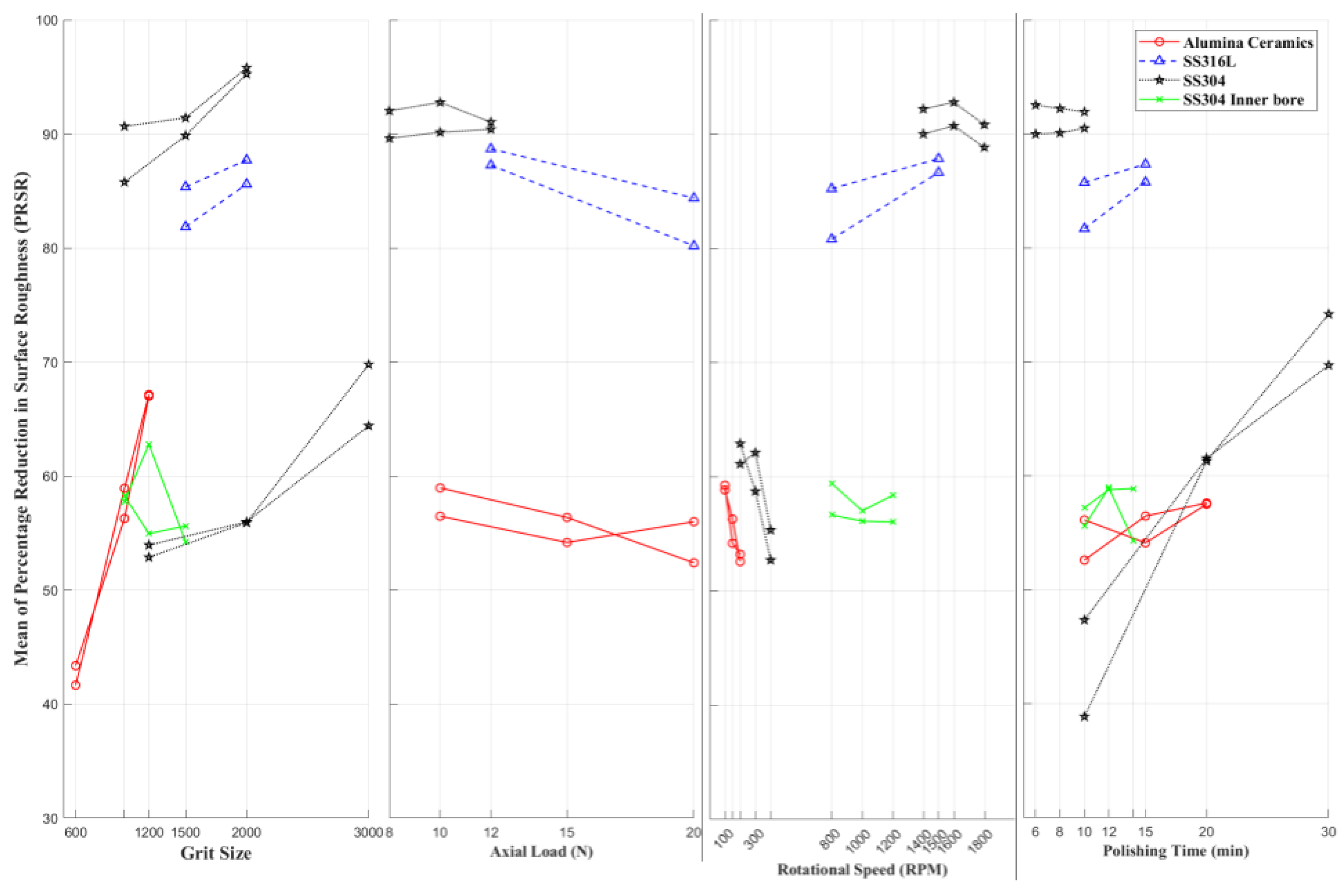
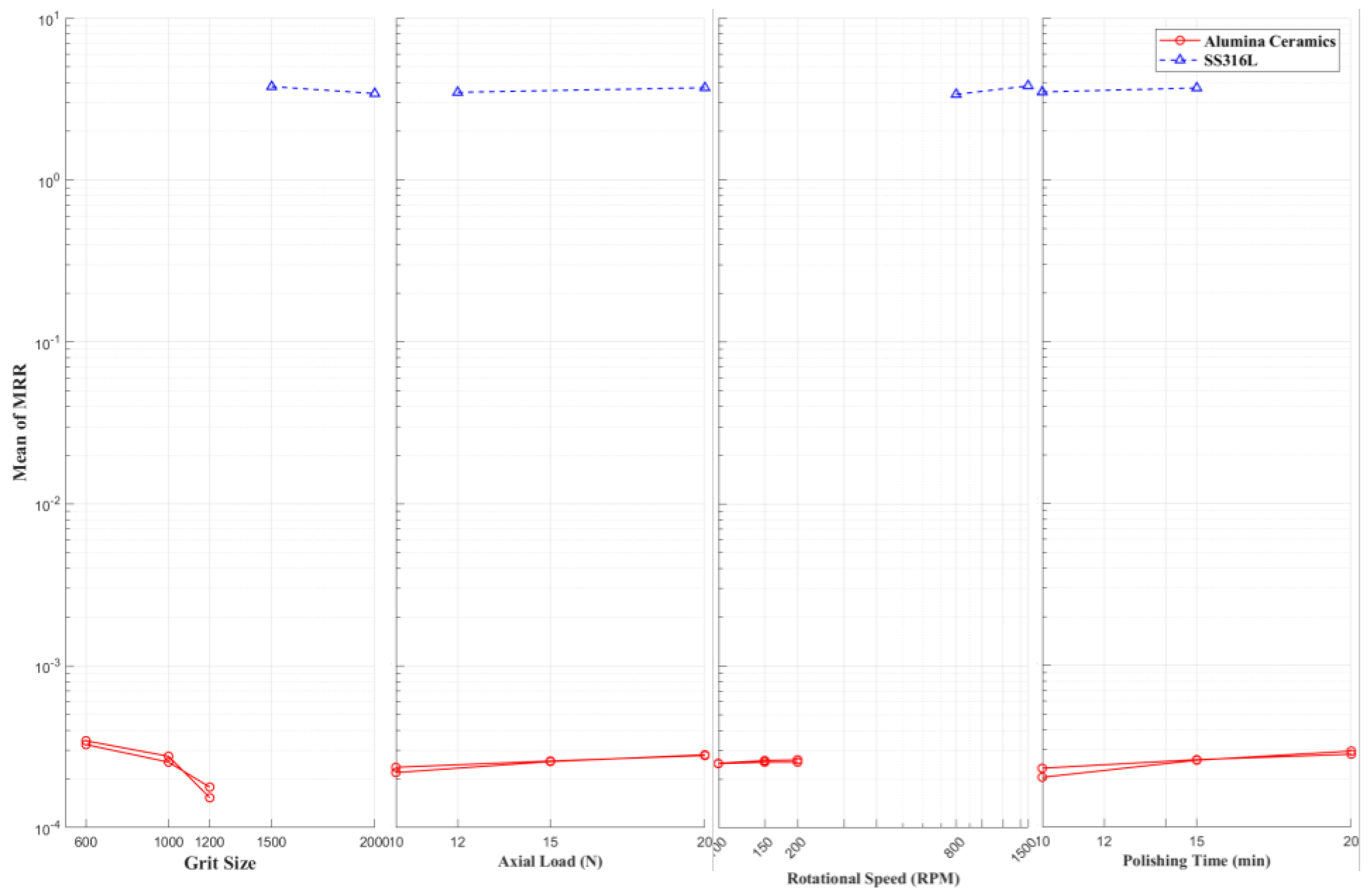
Figure 1.
Main Effects plot of the Mean of Percentage Reduction in Surface Roughness (PRSR) and Mean of MRR versus (a) Grit Size (b) Axial Load (c) Rotational Speed (d) Polishing Time for Alumina Ceramics, SS316L, SS304, Inner surface of the bore of SS304.
Figure 1.
Main Effects plot of the Mean of Percentage Reduction in Surface Roughness (PRSR) and Mean of MRR versus (a) Grit Size (b) Axial Load (c) Rotational Speed (d) Polishing Time for Alumina Ceramics, SS316L, SS304, Inner surface of the bore of SS304.
Effects of various process parameters on axial loading, feed rate, polishing time, and voltage applied on the surface finish of SS304 were studied by Pawade et al. [41,42].
Figure 2.
Effect of (a) Operation (b) Grit Size (c) Rotational Speed (d) Voltage (e) Polishing Time versus surface roughness (f) comparison of surface before and after the EPDAP process for SS304 inner bore surface.
Figure 2.
Effect of (a) Operation (b) Grit Size (c) Rotational Speed (d) Voltage (e) Polishing Time versus surface roughness (f) comparison of surface before and after the EPDAP process for SS304 inner bore surface.
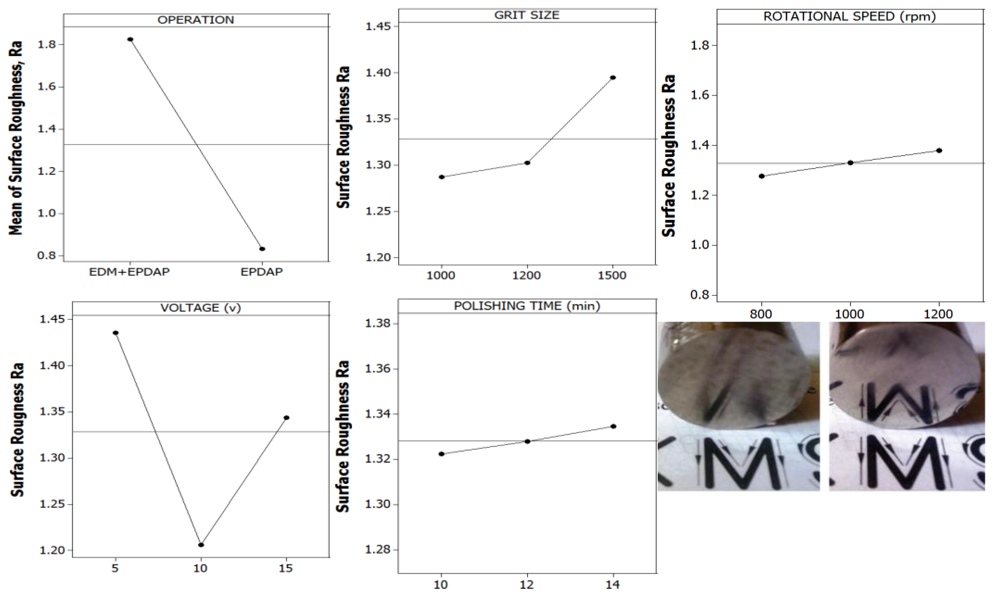
Figure 3.
Effect of (a) Grit Size (b) Rotational Speed (c) Polishing Time (d) Voltage versus surface roughness for SS304 surface.
Figure 3.
Effect of (a) Grit Size (b) Rotational Speed (c) Polishing Time (d) Voltage versus surface roughness for SS304 surface.
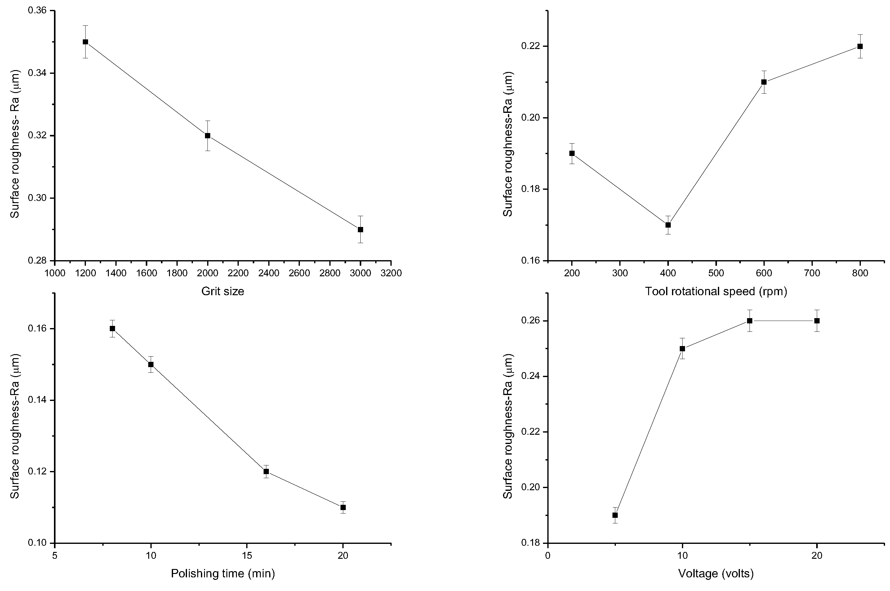
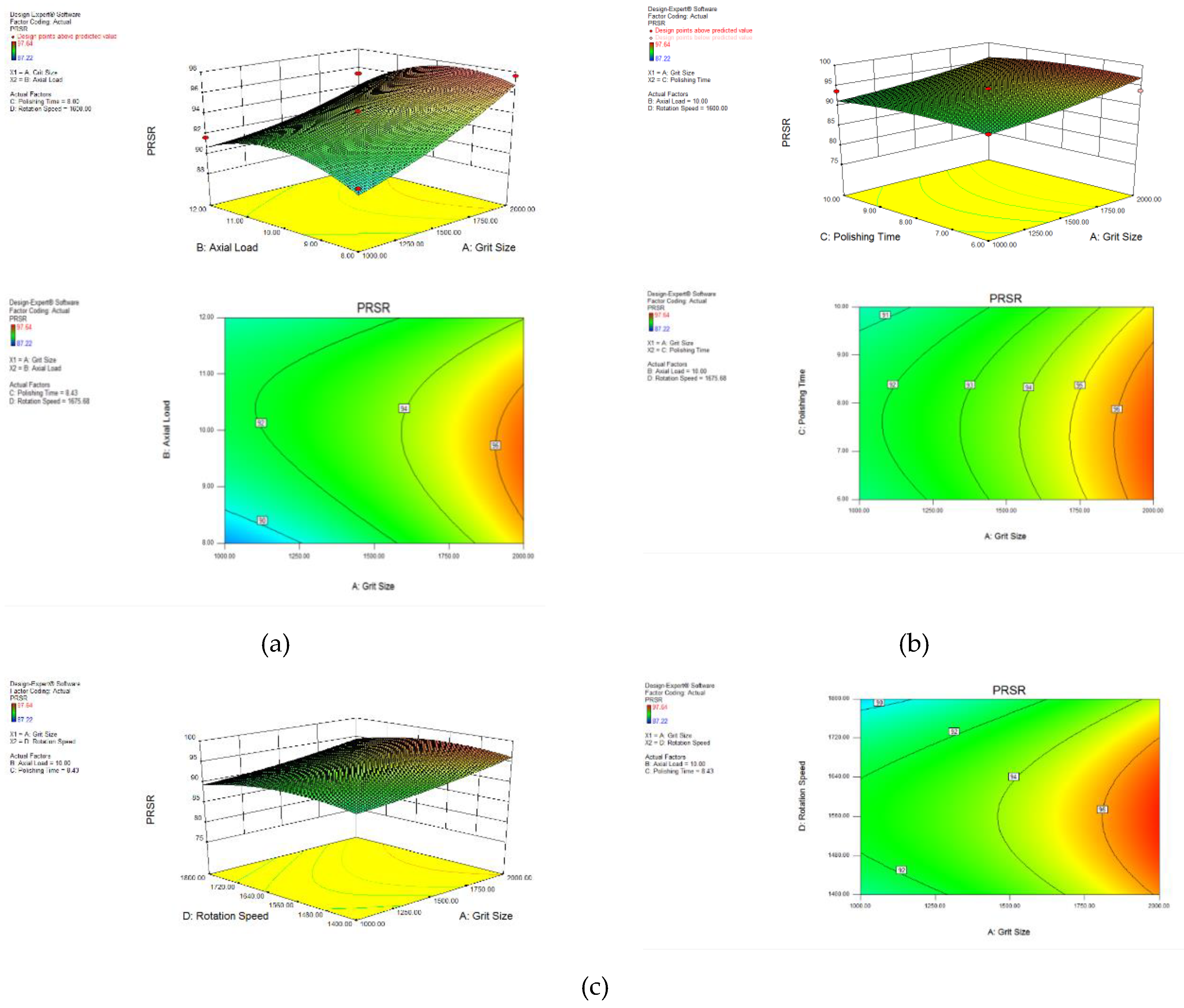
Figure 4.
3D and counter plots of effect of (a) grit size and axial load (b) polishing time and grit size (c) rotational speed and grit size on PRSR.
Figure 4.
3D and counter plots of effect of (a) grit size and axial load (b) polishing time and grit size (c) rotational speed and grit size on PRSR.
3.1.1. Effect of Polishing Time
A relationship between the surface roughness Ra values and the time the polishing is carried out has been represented graphically in Figure 5a. A rapid descent in the surface roughness value to 0.08 μm is achieved in a span of 2 minutes, while for the period between 2 to 8 minutes, the surface roughness value reduces from 0.08 to 0.03μm. However, no further improvement in surface roughness value is obtained during the polishing after 8 minutes. The polishing of 8 minutes is the optimum period to achieve a superior surface finish. It is observed from the main effects plots in Figure 2 between the polishing time and the means of arithmetic average roughness Ra that at higher polishing time (14 Min.) the surface roughness value is more as compared to the Ra after polishing of 10 Min. This could be due to the brittleness of the surface to be polished. As the contact duration of rotating polishing wheel is more, more number of micro asperities are broken in case of stainless steel. Hence, as polishing time increases Ra value also increases.
3.1.2. Effect of Axial Loading
A correlation between the surface finish and the axial load is represented in Figure 5b, which reveals that as the axial load rises from 2 to 11 N, the surface roughness value drops one order in magnitude from 0.4 to 0.04 μm. Similarly, the surface finish decreases with the intensification in the load from 11 to 14 N. Hence, the axial load was fixed at 11N for the polishing [20,43].
For higher axial loads, penetration of the abrasives occurs. The polished surface undergoes excessive, deep scratching revealed by Pawade and Rayate et al. [24,41] in Supplementary Figure S2c.
3.1.3. Effect of Rotating Speed of the Polishing Tool
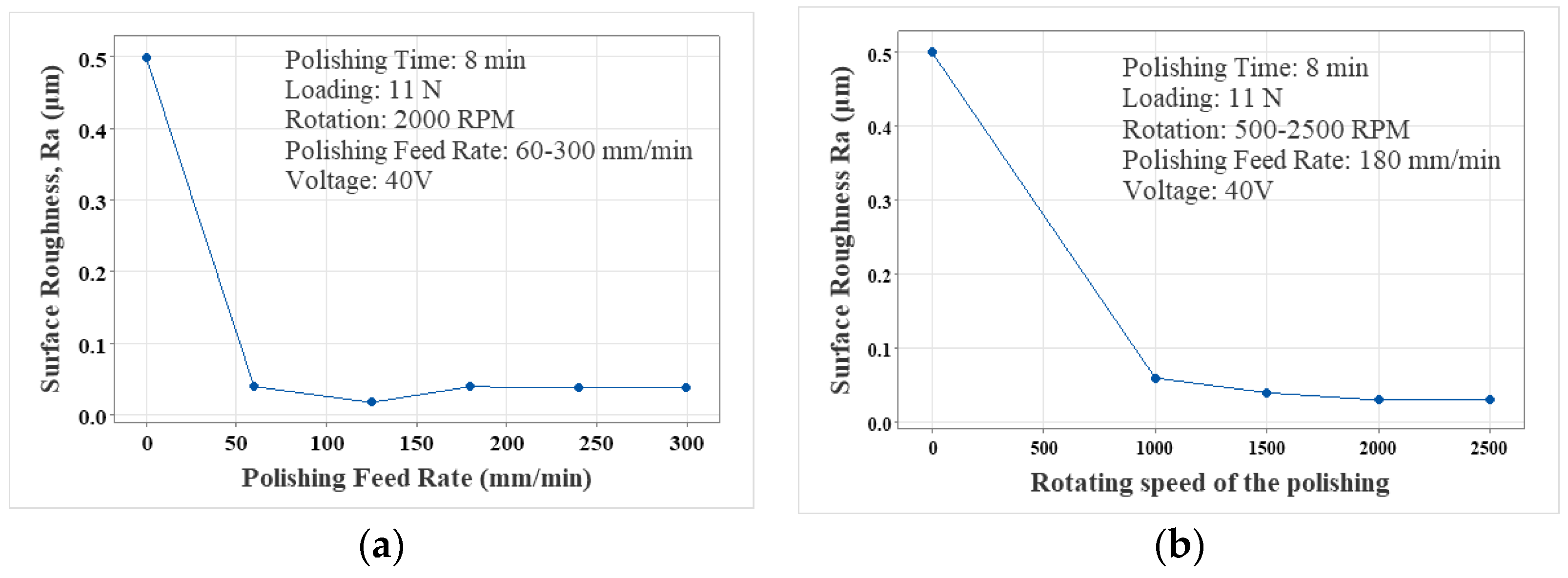
A correlation between the polishing device rotational velocity and surface roughness Ra is presented in Figure 6a. An increase in the speed of rotation of the polishing device from 500 to 2000 rpm results in a reduction in the surface roughness value from 0.5 to 0.03 μm. An increase in the rotating velocity of the polishing tool beyond 2000 rpm does not further improve the surface finish [44]. According to Figure 6b, an optimized value of 2000 rpm of the polishing tool rotational velocity resulted in the best surface finish. It is observed from the main effects plots in Figure 2 between the rotational speed and the means of arithmetic average roughness Ra that at higher level of rotational speed 1200 rpm the polished surface shows higher Ra and at lower level of rotational speed 800 rpm, the polished surface shows lower Ra value. As the rotational speed of the polishing tool increases from 800 rpm to 1200 rpm, the centrifugal force acting on the abrasive particles increases which helps in indenting the abrasive particles into the workpiece surface thus able to remove the micro scratches of earlier operations and hence reducing surface roughness. But beyond 1000 rpm, the centrifugal force is not able to hold the abrasive particles on the polishing tool due to increase in rotational speed of the tool and the shallow indentations produced earlier are affected because there is only contact of abrasive particles with the workpiece surface without polishing. Therefore, beyond 1000 rpm, the surface roughness value increases.
3.1.4. Effect of Feed Rate
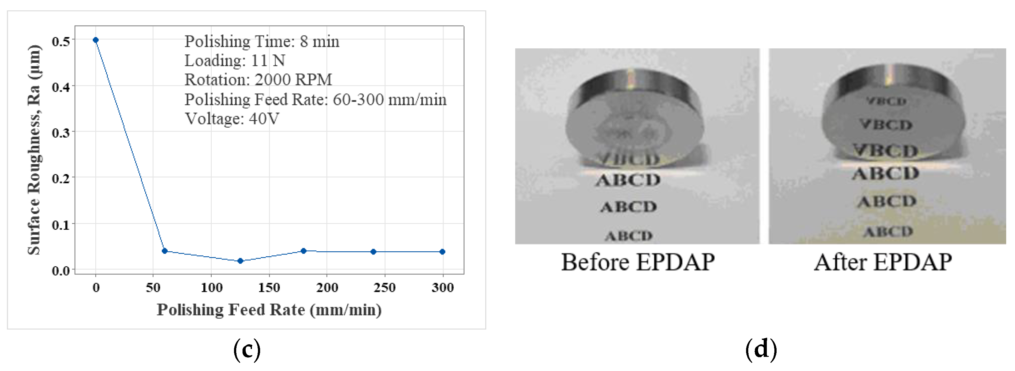
Figure 6a illustrates the dependence of feed rate on surface finish Ra during the polishing. It can be observed that an increase from 60 to 300 mm/min in the value of the feed rate leads to a variation of surface roughness between 0.02 to 0.04 μm occurs, which reveals that the feed rate does not have a substantial effect on the value of surface roughness Ra [20,24].
Figure 6.
Effect of polishing tool (a) feed rate (b) rotating speed (c) voltage on the surface roughness (d) demonstration of the phenomenon of reflectivity from the finished samples before and after EPDAP.
Figure 6.
Effect of polishing tool (a) feed rate (b) rotating speed (c) voltage on the surface roughness (d) demonstration of the phenomenon of reflectivity from the finished samples before and after EPDAP.
3.1.5. Effect of Voltage between the Auxiliary Electrode and Polishing Tool
It is observed from Figure 6c that the voltage does not have a significant effect on the surface finish. An increase in the voltage leads to a rise in the amount of particles settled on the polishing tool. Due to limitations in the deposition volume for the polishing tool in the micro-holes of the non-woven fabric, the non-woven fabric thickness increases as the particles get deposited over the non-woven fabric. Figure 6d shows the reflection of surfaces before and after the EPDAP.
It is also observed from the main effects plots in Figure 2 between grit size and the means of arithmetic average surface roughness, Ra that at higher level of grit size (1500), the polished surface shows higher surface roughness value, i.e., for the lower abrasive particle size, the surface roughness observed is higher. This could be due the size of grooves produced by individual particle at grit size 1000 is higher than the grooves produced by particle at 1500.
The EPDAP process is a very efficient technology to enhance the surface finish of 304 stainless steel. In this investigation, an enhancement in the surface finish value from 0.44 µm to 0.074 µm due to EPDAP, respectively, could be achieved. A substantial refinement in the surface finish was attained by a maximum reduction of 90.47% in surface roughness values. It is seen that the axial load set above 12 N produces a poor surface finish. Thus, a threshold value of the axial load is found to be 12 N. Further, it is found that the threshold rotational speed is 800 rpm. Beyond that, the surface quality degrades. The surface had lower roughness when polishing was done up to 10 min. But as the polishing time increases, the surface roughness increases. The optimized polishing parameters to achieve a superior surface finish are the 800 rpm rotation speed of the polishing tool with a 12 N axial load for a 10-minute polishing duration.
The scanning electron microscope (SEM) photograph shows that most surface variations are eliminated after the EPDAP process. The workpiece surface shows very few surface damages after EPDA polishing when conducted at optimum parameter setting.
3.2. SS316L
For applications desired to have excellent corrosion resistance, SS316L stainless steel is extensively employed [20,45,46,47,48,49,50]. The experiments were planned, and the control parameters and their levels were selected to optimize the performance of SS316L EPDAP, which is shown in Supplementary Figure S2f,h [51,52,53]. Full factorial method is used to design the experiment. The base’s material is polypropylene with a density of 250 kg/m3. The primary components of the electrolyte silicon carbide abrasives alongside equal moles of sodium hydroxide in pure water. 1200 cm3 of pure water is used for the preparation of electrolyte in which 0.2 kg of abrasive silicon carbide particles are added while NaOH is added as an additive to manipulate the acidity of the electrolyte post continuous magnetic mixing mechanism. A pH value of 9 is desirable for the optimal functioning and employment of the electrolyte for polishing SS316L. Supplementary Figure S2c,e reveals the actual and schematic experimental setup for the EPDAP of SS316L.
Effects of polishing parameters for polishing SS316L like grit size, axial loading, duration of polishing, feed rate, rotating speed, and voltage [19,54] applied on the MRR and surface roughness were studied by Pawade and Gaikhe et al. [51].
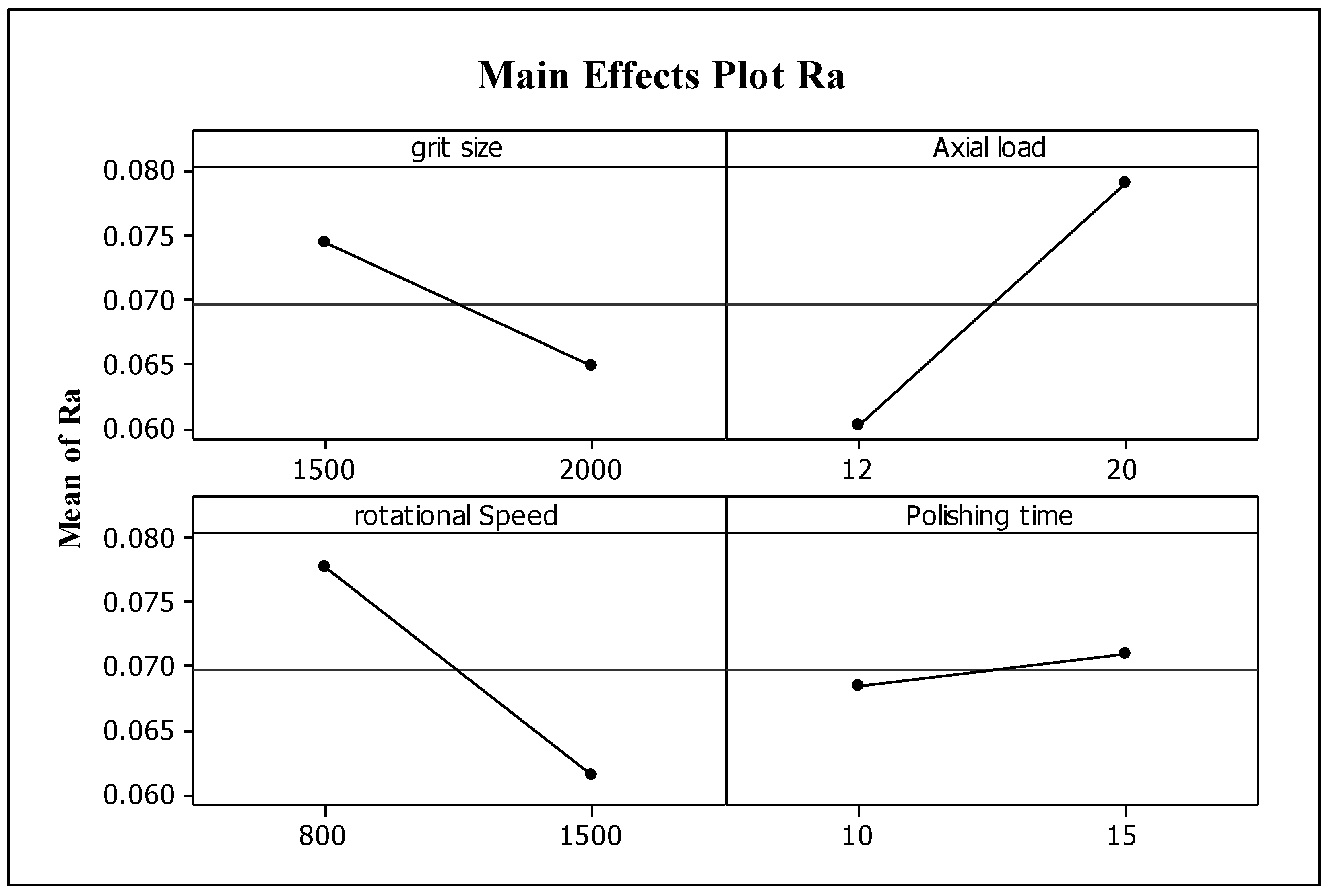
Figure 7.
Main effects plots for means of arithmetic average surface roughness Ra (a) Grit Size (b) Axial Load (c) Rotational Speed (d) Polishing Time.
Figure 7.
Main effects plots for means of arithmetic average surface roughness Ra (a) Grit Size (b) Axial Load (c) Rotational Speed (d) Polishing Time.
3.2.1. Effect of Grit Size
The main effects plot presented in Figure 1a between surface roughness, Ra, and grit size reveals that a better surface finish can be achieved with a greater level of grit size (2000) which implies the Ra value decreases with a decrease in the particle size of the abrasives [24,55]. This could be due to the quantity of fine particles will be higher than the coarse one at the same concentration level. In addition, smaller particles moves at a faster speed in the electrolyte. Further the large surface area is available for the smaller particles, its deposition rate on the tool is higher than that of the largest sized abrasive particles. This causes the reduction of pressure on particle grains due to large number of active grains present which distribute pressure on the larger area. Therefore smaller particles produce smooth surface with less damage to the surface and thus the surface roughness is less as compared to larger abrasive particles in the electrolyte. It can also be observed from the correlation of the mean of MRR and grit size presented in Figure 1b that the MRR is highest at a smaller grit size of 1500, which implies higher MRR from small sizes of abrasive particles. It can be inferred that an increase in the depth of penetration caused by the rise in particle size leads to higher material removal.
3.2.2. Effect of Axial Loading
The main effects plot in Figure 1b presents a correlation between the surface roughness and axial load. It can be observed from the relationship that a good surface finish can be obtained for lower axial loads (12 N). The surface deteriorates by increasing the load to 20 N from 12 N. This could be due to an increase in the axial load on workpiece that causes more vibrations in EPDA polishing setup and resulted into increase in surface roughness Ra, other possibility might be the higher load on the workpiece causing more pressure. As a consequence more abrasive penetration in to the workpiece and hence, more friction between polishing tool and workpiece thus increases the material removal rate and hence the surface roughness Ra also. Figure 1b, which represents a correlation between the mean MRR and axial load, reveals that with the increment of the axial load from 12 N to 20 N, the MRR elevates. It can be inferred that a higher load means more enormous penetrations of the abrasives. From a chemical aspect, it can be implied that the number of reaction sites between the workpiece and the abrasives would increase due to an increase in the load.
3.2.3. Effect of Rotating Speed of the Polishing Tool
A graphical correlation between the surface roughness and the rotational speed presented in Figure 1c reveals that a superior surface finish is obtained for a more immense rotational speed of 1500 rpm. However, the SiC particles become more mobile with increased rotational speed. At that time, electro-osmosis and electrophoretic phenomena took place, i.e., blunt abrasives were replaced with new fresh abrasives, so there was less damage on the workpiece surface. Therefore, a significant decline in the surface roughness values can be observed while increasing the polishing tool rotational velocity from 800 rpm to 1500 rpm. A similar correlation is obtained between the rotational speed and the MRR, which resembles an increase in the amount of material removed with an increase in the rotational velocities of the polishing tool. The rapid rate of plucking is achieved with a higher rotational speed.
3.2.4. Effect of Polishing Time
From Figure 1d, it is evident that the polishing duration between 10 to 15 minutes has no significant impact on the polishing time on the surface finish. However, from the main effects plot presented in Figure 1d, it can be observed that at a higher polishing time of 15 minutes, the MRR is higher, which can be seen as an increase in the contact duration of the workpiece and abrasives. Due to large contact period, some of the abrasive particles inside the non-woven fabrics lose their cutting ability and become dull and when these particles come in contact with the workpiece may cause increase in the surface roughness Ra. Figure 8 shows 3-dimensional surface roughness and 100X microscopic image after EPDAP for t= 10 min, L= 12 N, grit size=2000, S= 1500 rpm. For a rotational speed of 800 rpm, axial load of 20 N, grit size of 1500, and the polishing duration of 10 minutes, a higher surface roughness Ra value of 98.68 nm is obtained.
3.3. Alumina Ceramics
Alumina Ceramic exhibits high hardness and resistance to wear, thermal shock, and low thermal expansion and density [56]. Dies, molds, and optical materials widely use alumina ceramics materials [57,58]. Before performing EPDA Polishing experiments, whose schematic and the setup are represented in Supplementary Figure S2d,e, the abrasive slurry was prepared, whose pH value was maintained at 9, by adding NaOH in a mixture of SiC particles and water. The slurry is continuously stirred using a magnetic stirrer until the pH value reaches 9.
For alumina ceramics, parameters affecting the surface roughness such as axial loading, polishing time, rotating speed, feed rate, and voltage were studied by Pawade et al. [20,24,27,35,51].
3.3.1. Effect of Grit Size
Figure 1a reveals that a superior surface finish is achieved at grit sizes of higher level 1200, which means a smaller abrasive particle size. This could be because the size of grooves produced by an individual particle at grit size 600 is more significant than that produced by a particle at 1200 W1>W2 as shown in Figure 9a,b. Smooth surfaces are achieved with the smaller size of the particles. Hence the percent reduction in surface roughness increases as the grit diameter reduces and grit size increases.
It is observed from the main effects plots grit size and mean of MRR shown in Figure 1a, that at 600 grit size, material removal rate is higher. This is because as the particle size is increased the amount of material removed particle is more per unit time. Hence the material removal rate seems to be higher at grit size 600, than at grit size 1200.
3.3.2. Effect of Axial Loading
A poor surface finish is obtained for higher values of an axial load of about 20 N, revealed from the experimental investigations and represented in Figure 1b. Also, with an increase in the axial loads from 15N to 20N, a deterioration in the surface quality can be observed. This could be due to increased axial loading, which causes more scratches on the surface due to more penetration of the abrasive particles into the workpiece as seen in Figure 9c,d. An increase in the percent reduction of the surface roughness is achieved as the load progresses from 15N to 20N.
It is observed from the main effects plots axial load and mean of MRR in Figure 1b, the material removal rate is increased as the axial load increases from 10N to 20N. The reason behind that is the higher load mean larger penetration of abrasive particles. As the penetration of the particles increase the amount of material removed per particle is also increase. Hence larger the axial load, larger the material removal. However, when the mean of MRR for alumina ceramic is compared to that for SS316L, the MRR for alumina ceramic is 4 orders of magnitude lower than the SS316L.
3.3.3. Effect of Rotating Speed of the Polishing Tool
Poor surface finish is obtained due to the high rotational velocity of the polishing device, as represented in Figure 1c. Superior surface finish is achieved at lower rotational speed values of 100. This could be due to the bluntness of abrasive particles within the non-woven fabric at higher polishing tool rotational velocity due to an interaction with the brittle workpiece surface, thereby losing its cutting ability and increasing the surface roughness Ra. Hence, an increase in the speed of rotation of the polishing device leads to a decrease in the percent reduction of the surface roughness.
It is observed from the main effects plots rotational speed and mean of MRR in Figure 1c, it is seen from the main effect plots that rotational speed of the tool not significantly affects the material removal rate in case of brittle material. This is because at higher rotational speed of the tool on the brittle work piece surface will cause bluntness in some of the abrasive particles inside the non – woven fabric. This will cause in lowering the MRR at higher rotational speed. From graph it is seen that MRR lowered between the speeds 150 to 200 rpm.
3.3.4. Effect of Polishing Time
Figure 1d shows that for a higher polishing time (20 min.), a polished surface’s surface roughness is lower than the surface roughness after polishing 10 min. This could be due to the brittleness of the workpiece surface to be polished. As the contact duration of the rotating polishing tool increases, more surface abrasive grains are broken, i.e., intergranular fracture mechanism, producing a smoother surface as the polishing time is higher. The above graph demonstrates that the percent reduction in surface roughness increases with the polishing time increment from 15 min to 20 min.
It is observed from the main effects plots polishing time and mean of MRR in Figure 1d, it is seen from the main effect plots, that as the polishing time increases from 10 min to 20 min. the material removal rate also increases. This is because more amount of material is removed as time increases.
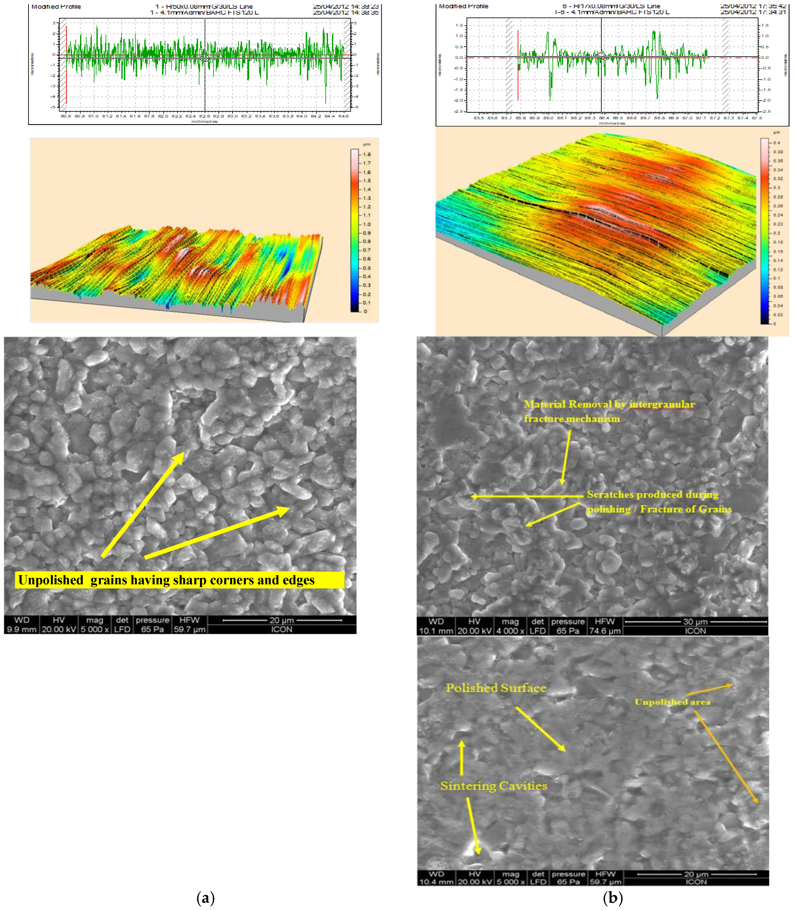
Figure 10a shows 2D surface profile of the unpolished specimen. The surface roughness (peaks and valleys) is distributed in the range of -1 to 1 µm approximately. The surface roughness values are, Ra 0.3108 µm, Rq 0.4352 µm, Rv 0.9338 µm, Rt 1.2432 µm. Scanning electron microscopy image for surface of unpolished alumina ceramic specimen, taken at 5000X zoom level shows the closely packed structure of alumina grains on the surface of the specimen. The grains are having sharp corners and edges. i.e., more peaks valleys. Figure 10b shows the 2D surface profile of the polished specimen. It is observed from Figure 10b that EPDA polished experiments result in the formation of even surface texture (peaks and valleys) which results in lower surface roughness. The roughness value Ra = 0.3108 µm, found at the polishing duration of 20 minutes, grit size – 1200, axial loading of 15N, and a rotational speed of 100 rpm. Figure 10b clearly shows the closely packed sharp grains of the alumina ceramic is cut during the polishing process by the intergranular fracture mechanism due to the polishing action.
4. Conclusions
For SS304 steel the surface roughness Ra achieved is 0.035 µm (35 nanometers) whose surface roughness before EPDA polishing was 0.29 µm. Thus, percentage reduction in surface roughness (PRSR) achieved is 87.93%. The surface roughness Rp achieved is 0.14 µm whose surface roughness before EPDA polishing was 0.67 µm. Thus, percentage reduction in surface roughness (PRSR) achieved is 79.10%. The optimum polishing performance for the PRSR-Ra is obtained at abrasive grit size of 3000, polishing time of 30 minutes and polishing tool rotational speed of 200 rpm. The optimum polishing performance for the PRSR-Rp is obtained at abrasive grit size of 3000, polishing time of 30 minutes and polishing tool rotational speed of 400 rpm. The factors abrasive grit size and polishing time are more significant during EPDA polishing of SS304 steel whereas the factor polishing tool rotational speed is less significant in influencing the PRSR during EPDA polishing. The modeling of surface roughness is done to study the EPDA polishing theoretically. The optimum reflectivity performance for the PIRL obtained is 69.07% at abrasive grit size of 3000, polishing time of 30 minutes and polishing tool rotational speed of 300 rpm.
The quality of the inner bore surface of SS304 polished by using electrophoretic deposition assisted polishing (EPDAP) method was distinctly improved in short period of time. The surface roughness obtained up to 0.50 µm in these experiments whose surface roughness before EPDAP method was 3.26 µm hence surface roughness reduction is achieved 84.66 %. For EDM+EPDAP process PRSR is achieved about 70%. The optimum polishing performance for the surface roughness is obtained at abrasive grit size 1000, rotational speed (S) = 800 rpm, polishing time (T) =12 min and voltage is at 10 volts in case of EPDAP Process. The surface roughness is decreases with decrease in abrasive particle size. The Operations, grit size and rotational speed are more significant for electrophoretic deposition assisted polishing of SS304 whereas the factor polishing time and voltage is less significant for electrophoretic deposition assisted polishing of Stainless Steel.
The surface of SS316L polished achieved the surface roughness obtained up to 0.04557 µm (45.57 nm) in these experiments whose surface roughness before EPDAP method was 0.75 µm. Hence surface roughness reduction is achieved 93.92 %. The optimum polishing performance for the surface roughness is obtained at abrasive grit size 2000, Axial load (L) = 12 N, Rotational speed (S) = 1500 rpm, Polishing time (t) = 10 min. the surface roughness is decreases with decreasing in abrasive particle size. EPDAP also improves the in surface quality in terms of reflectivity. The MRR= 4.2 mg/min is obtained maximum at abrasive grit size 1500, Axial load (L) = 20 N, Rotational speed (S) = 1500 rpm, Polishing time (t) = 15 min. The grit size, factors axial load and rotational speed are more significant for electrophoretic deposition assisted polishing of SS316L whereas the factor polishing time is less significant for electrophoretic deposition assisted polishing of SS316L.
The surface of alumina ceramics polished by using electrophoretic deposition assisted polishing (EPDAP) method, the surface roughness was obtained up to 0.404 mm in these experiments whose surface roughness before EPDAP method was 1.142 mm of alumina ceramics hence surface roughness reduction is achieved 73.75 %. The optimum polishing performance for the surface roughness is obtained at abrasive grit size 1200, axial load (L) = 10 N, rotational speed (S) = 100 rpm, polishing time (T) =10 min. The surface roughness is decreases with decreasing in abrasive particle size. The MRR = 0.00040 mg / min is obtained maximum at abrasive grit size 600, axial load (L) =20 N, rotational speed(S) =200 rpm, polishing time (T) =10 min. The factors grit size, axial load and polishing time are more significant for electrophoretic deposition assisted polishing of alumina ceramics whereas the factor rotational speed is less significant for electrophoretic deposition assisted polishing of alumina ceramics.
In this paper, the electrophoretic deposition-assisted polishing (EPDAP) method was explained in which different surfaces of SS304, SS316L, and alumina ceramics were polished using SiC mixed NaOH and Al2O3 mixed NaOH electrolyte. The experiments were designed to determine a correlation between the surface properties and the process parameters using RSM experimental design and TAGUCHI experimental design. By comparing the various processes and their experimental results based on literature findings, it was found that the electrophoretic deposition-assisted polishing process has the potential to become one of the most commonly used industrial super finishing applications, and there is remarkable scope for further work to enhance the understanding of EPDAP process. The factors like polishing time, axial load, and grit size are the most important for EPDAP. In contrast, the rotational speed and voltage aspects are less significant in most materials tested.
Supplementary Materials
The following supporting information can be downloaded at: Preprints.org, Figure S1: title; Table S1: title; Video S1: title.
Author Contributions
Conceptualization, S.Y. and R.P.; methodology, S.Y. and R.P.; software, S.Y.; validation, S.Y.; formal analysis, S.Y. and R.P.; investigation, S.Y.; resources, S.Y. and R.P.; data curation, S.Y.; writing—original draft preparation, S.Y.; writing—review and editing, S.Y.; visualization, S.Y. and R.P.; supervision, R.P.; project administration, R.P.; funding acquisition, S.Y. and R.P. All authors have read and agreed to the published version of the manuscript.
Funding
This research received no external funding
Data Availability Statement
The authors declare that all data supporting the findings of this study are available within the article and its supplementary information files.
Acknowledgments
I am deeply thankful to my informants Yogesh Gaikhe, Vilas Katare, Arvind Chavan, Sandeep Huddedar, Mahesh Rayate, Prasad Ingale, Maruti Nikam, Sameer Paritkar, Abhishek Bhide, Nikhil Khatekar, Shraddha Rangari, Madhuri Choudhari, Mahesh Chavan, Mandar Choudhari, Damodar Hindola, Sagar Sakharkar, Manisha Debaje, Monika Salunkhe, and Vilas Shinde. I want to acknowledge and appreciate their help and transparency during this research. My special and hearty thanks to Prof. (Dr.) Prakash K. Brahmankar who encouraged and directed this research.
Conflicts of Interest
The authors declare no conflicts of interest
References
- J. Ikeno, Y. Tani, and H. Sat0, “Development of Highly Homogeneous Pellets Applying Electrophoretic Deposi-tion of Ultrafine Abrasives for Nanometer Grinding,” CIRP Ann.- Manufactur. Technol, vol. 43, pp. 319–322, 1994. [CrossRef]
- R. Saraf, S. P. Yadav, and M. Sadaiah, “Precision Photochemical Machining,” in Micro and Precision Manufac-turing, vol. 1, Kapil Gupta, Ed., Springer, 2018, pp. 41–70. [CrossRef]
- R. Saraf and S. P. Yadav, “Fundamentals of bare-metal stents,” in Functionalised Cardiovascular Stents, Elsevier, 2018, pp. 27–44. [CrossRef]
- V. K. Jain, “Magnetic field assisted abrasive based micro-/nano-finishing,” J Mater Process Technol, vol. 209, no. 20, pp. 6022–6038, Nov. 2009. [CrossRef]
- M. Das, V. K. Jain, and P. S. Ghoshdastidar, “Nanofinishing of flat workpieces using rotation-al-magnetorheological abrasive flow finishing (R-MRAFF) process,” International Journal of Advanced Manufactur-ing Technology, vol. 62, no. 1–4, pp. 405–420, Sep. 2012. [CrossRef]
- V. K. Jain, “Abrasive-based nano-finishing techniques: An overview,” Machining Science and Technology, vol. 12, no. 3, pp. 257–294, Jul. 2008. [CrossRef]
- D. Keck, S. Ravi, S. Yadav, and R. Martinez-Duarte, “The Effect of Different System Parameters on the Movement of Microbial Cells Using Light-Induced Dielectrophoresis,” Micromachines (Basel), vol. 15, no. 3, p. 342, Feb. 2024. [CrossRef]
- S. P. Yadav and R. S. Pawade, “Manufacturing Methods Induced Property Variations in Ti6Al4V Using High-Speed Machining and Additive Manufacturing (AM),” Metals (Basel), vol. 13, no. 2, p. 287, Jan. 2023. [CrossRef]
- R. Kundiya et al., “Analysis of hole characteristics in Mechanical Micro Drilling of CFRP-Ti6Al4V Stack Compo-site.
- P. A. McKeown, “The Role of Precision Engineering in Manufacturing of the Future,” CIRP Annals, vol. 36, no. 2, pp. 495–501, 1987. [CrossRef]
- S. Khalaj Amnieh, P. Mosaddegh, and A. Fadaei Tehrani, “Study on magnetic abrasive finishing of spiral grooves inside of aluminum cylinders,” International Journal of Advanced Manufacturing Technology, vol. 91, no. 5–8, pp. 2885–2894, Jul. 2017. [CrossRef]
- J. Ikeno, Y. Tani, and A. Fukutani, “Development of Chipping-Free Dicing Technology Applying Electrophoretic Deposition of Ultrafine Abrasives,” CIRP Annals, vol. 40, no. 1, pp. 351–354, 1991. [CrossRef]
- S. Yadav, A. Saraf, and M. Sadaiah, “Analysis of Undercut for SS304 in Photochemical Machining,” in Proceed-ings of the International Conference on Communication and Signal Processing 2016 (ICCASP 2016), Paris, France: Atlantis Press, 2017, pp. 284–289. [CrossRef]
- M. Ravi Sankar, V. K. Jain, and J. Ramkumar, “Rotational abrasive flow finishing (R-AFF) process and its effects on finished surface topography,” Int J Mach Tools Manuf, vol. 50, no. 7, pp. 637–650, Jul. 2010. [CrossRef]
- S. C. Jayswal, V. K. Jain, and P. M. Dixit, “Modeling and simulation of magnetic abrasive finishing process,” In-ternational Journal of Advanced Manufacturing Technology, vol. 26, no. 5–6, pp. 477–490, Sep. 2005. [CrossRef]
- W. C. Chen, K. L. Wu, and B. H. Yan, “A study on the application of newly developed magneto-elastic abrasive to improving the surface roughness of the bore,” International Journal of Advanced Manufacturing Technology, vol. 73, no. 9–12, pp. 1557–1566, 2014. [CrossRef]
- H. Yan, H. J. Tzeng, F. Yuan Huang, Y. C. Lin, and H. M. Chow, “Finishing effects of spiral polishing method on micro lapping surface,” Int J Mach Tools Manuf, vol. 47, no. 6, pp. 920–926, 07. 20 May. [CrossRef]
- Y. Tani, T. Saeki, Y. Samitsu, K. Kobayashi, and Y. Sato, “lnfeed Grinding of Silicon Wafers Applying Electro-phoretic Deposition of Ultrafine Abrasives,” CIRP Annals, vol. 47, pp. 245–248, 1998. [CrossRef]
- H. P. Tsui, B. H. Yan, W. Te Wu, and S. T. Hsu, “A study on stainless steel mirror surface polishing by using the electrophoretic deposition method,” Int J Mach Tools Manuf, vol. 47, no. 12–13, pp. 1965–1970, Oct. 2007. [CrossRef]
- Arvind Chavan, Yogesh Gaikhe, Sandeep Huddedar, and Raju Pawade, “3D Surface Characterization of Elec-trophoretic Deposition Assisted Polishing of SS316L,” Journal of Applied Sciences, vol. 12, no. 10, pp. 929–937, 2012. [CrossRef]
- H. Yan, H. J. Tzeng, F. Yuan Huang, Y. C. Lin, and H. M. Chow, “Finishing effects of spiral polishing method on micro lapping surface,” Int J Mach Tools Manuf, vol. 47, no. 6, pp. 920–926, 07. 20 May. [CrossRef]
- M. J. González-Morales, R. Mahillo-Isla, E. Gago-Ribas, and C. Dehesa-Martínez, “Complex polar coordinates in electromagnetics,” J Electromagn Waves Appl, vol. 25, no. 2, pp. 389–398, Jan. 2011. [CrossRef]
- H. Fong and D. H. Reneker, “Elastomeric Nanofibers of Styrene-Butadiene-Styrene Triblock Copolymer,” 1999.
- S. Yadav, A. Sangoi, and R. Pawade, “Development of Mathematical Model and Characterization of Internal Surface obtained by Elasto-Abrasives Magneto-spiral Finishing (EAMSF),” J Manuf Sci Eng, pp. 1–25, Jul. 2022. [CrossRef]
- M. A. Skotnikova, N. A. Krylov, and A. A. Popov, “Structural and Phase Transformation in Metals at High-Speed Cutting and Tool Wear,” in Procedia Engineering, Elsevier Ltd., 2017, pp. 777–782. [CrossRef]
- T. F. Mao, S. C. Yang, F. C. Tsai, J. C. Hung, and B. H. Yan, “Experimental investigation of abrasive jet polishing on the free-form machined surfaces of SKD61 mold steel using SiC particles,” Materials and Manufacturing Pro-cesses, vol. 25, no. 9, pp. 965–973, Sep. 2010. [CrossRef]
- S. P. Yadav, H. Shaikh, and R. S. Pawade, “Assessment of Optical Performance of Aspheric Germanium Lens Manufactured Using Single Point Diamond Turning,” in Volume 1: Processes, American Society of Mechanical Engineers, Jun. 2017. [CrossRef]
- R. Mohan and N. R. Babu, “Ultrafine finishing of metallic surfaces with the ice bonded abrasive polishing pro-cess,” in Materials and Manufacturing Processes, Apr. 2012, pp. 412–419. [CrossRef]
- Y. B. Tian, Z. W. Zhong, S. T. Lai, and Y. J. Ang, “Development of fixed abrasive chemical mechanical polishing process for glass disk substrates,” International Journal of Advanced Manufacturing Technology, vol. 68, no. 5–8, pp. 993–1000, Sep. 2013. [CrossRef]
- M. R. Sankar, V. K. Jain, and J. Ramkumar, “Experimental investigations into rotating workpiece abrasive flow finishing,” Wear, vol. 267, no. 1–4, pp. 43–51, Jun. 2009. [CrossRef]
- D. P. Updike and A. Kalnins, “Contact Pressure Between an Elastic Spherical Shell and a Rigid Plate,” Journal of Applied Mechanics-Transactions of the ASME, pp. 1110– 1114, 1972, [Online]. Available: http://asmedigitalcollection.asme.org/appliedmechanics/article–pdf/39/4/1110/5452680/1110_1pdf.
- M. A. Skotnikova, V. P. Artemyev, S. A. Shasherina, O. V. Paitova, and G. V. Tsvetkova, “Tribotechnical properties of nanostructured coppernickel coatings,” in Lecture Notes in Mechanical Engineering, Pleiades journals, 2019, pp. 61–71. [CrossRef]
- S. Witharamage et al., “Corrosion-resistant metallic coatings for aluminum alloys by cold spray,” Corros Sci, vol. 209, Dec. 2022. [CrossRef]
- M. A. Skotnikova, G. V. Tsvetkova, and N. A. Krylov, “Tribological properties of nanostructured diffusion layers of metal coatings,” in Key Engineering Materials, Trans Tech Publications Ltd., 2017, pp. 446–450. [CrossRef]
- S. Yadav, R. Waikar, R. Pawade, and S. Joshi, “Experimental analysis of orthogonal micro-machined surface features and chip morphology of AISI1215 steel by using EBSD method,” in Proceedings of the International Con-ference on Communication and Signal Processing 2016 (ICCASP 2016), Paris, France: Atlantis Press, 2017, pp. 304–310. [CrossRef]
- Q. Yuan, H. Qi, and D. Wen, “Numerical and experimental study on the spiral-rotating abrasive flow in polish-ing of the internal surface of 6061 aluminium alloy cylinder,” Powder Technol, vol. 302, pp. 153–159, Nov. 2016. [CrossRef]
- M. Wani, V. Yadava, and A. Khatri, “Simulation for the prediction of surface roughness in magnetic abrasive flow finishing (MAFF),” J Mater Process Technol, vol. 190, no. 1–3, pp. 282–290, Jul. 2007. [CrossRef]
- S. Singh and H. S. Shan, “Development of magneto abrasive flow machining process,” 2002.
- M. R. Sankar, S. Mondal, J. Ramkumar, and V. K. Jain, “Experimental investigations and modeling of drill bit-guided abrasive flow finishing (DBG-AFF) process,” International Journal of Advanced Manufacturing Technology, vol. 42, no. 7–8, pp. 678–688, Jun. 2009. [CrossRef]
- K. K. Kar, N. L. Ravikumar, P. B. Tailor, J. Ramkumar, and D. Sathiyamoorthy, “Performance evaluation and rheological characterization of newly developed butyl rubber based media for abrasive flow machining process,” J Mater Process Technol, vol. 209, no. 4, pp. 2212–2221, Feb. 2009. [CrossRef]
- R. S. Pawade, M. Rayte, P. Ingle, and S. Paritkar, “Some investigations on surface characteristics of SS304 using electrophoretic deposition assisted polishing (EDPAP),” in Proceedings of the 3rd International and 24th AMTDR Conference, B. Satyanarayana and K. Ramji, Eds., Vizag, Dec. 2010.
- Rabinowicz, L. A. Dunn, and P. G. Russell, “A Study of Abrasive Wear under Three-Body Conditions,” Wear, vol. 4, pp. 345–355, 1961.
- R. S. Walia, H. S. Shan, and P. Kumar, “Enhancing AFM process productivity through improved fixturing,” In-ternational Journal of Advanced Manufacturing Technology, vol. 44, no. 7–8, pp. 700–709, Oct. 2009. [CrossRef]
- Xi and, D. Zhou, “Modeling surface roughness in the stone polishing process,” Int J Mach Tools Manuf, vol. 45, no. 4–5, pp. 365–372, Apr. 2005. [CrossRef]
- S. Mali and A. Manna, “Simulation of surface generated during abrasive flow finishing of Al/SiCp-MMC us-ing neural networks,” in International Journal of Advanced Manufacturing Technology, Aug. 2012, pp. 1263–1268. [CrossRef]
- R. S. Walia, H. S. Shan, and P. Kumar, “Parametric optimization of Centrifugal Force-Assisted Abrasive Flow Machining (CFAAFM) by the Taguchi method,” Materials and Manufacturing Processes, vol. 21, no. 4, pp. 375–382, Jul. 2006. [CrossRef]
- V. B. Vukkum, J. Christudasjustus, T. Y. Ansell, A. Nieto, and R. K. Gupta, “Influence of carbon nanotubes on mi-crostructure and corrosion performance of additively manufactured 316L stainless steel,” Corros Sci, vol. 224, Nov. 2023. [CrossRef]
- M. A. Skotnikova, G. V. Tsvetkova, N. A. Krylov, E. K. Ivanov, V. V. Medvedeva, and N. V. Bezenkin, “Features of wear of abrasive grains depending on microcuttings speed of steels,” in Key Engineering Materials, Trans Tech Publications Ltd., 2016, pp. 189–194. [CrossRef]
- M. O’donnell, J. Budan, J. Mcguire, P. Jalagam, A. Kulkarni, and T. Y. Ansell, “Printing Hydrophobic Stainless Steel Graphene Composites,” in 2023 International Solid Freeform Fabrication Symposium, 2023, pp. 239–249. [CrossRef]
- Tsvetkova and, M. Skotnikova, “Engineering and research of wearability coating on the basis of high-strength steel,” in Proceedings of 9th International Scientific Conference, BALTTRIB 2017 - Dedicated to 100th Anniversary of Restitution of Lithuania, Aleksandras Stulginskis University, Jan. 2018; pp. 166–171. [CrossRef]
- Y. S. Gaikhe, A. M. Chavan, and R. S. Pawade, “Surface topography analysis in electrophoretic deposi-tion-assisted polishing of AISI 316L stainless steel,” Materials and Manufacturing Processes, vol. 28, no. 6, pp. 676–682, Jun. 2013. [CrossRef]
- R. S. Walia, H. S. Shan, and P. Kumar, “Enhancing AFM process productivity through improved fixturing,” In-ternational Journal of Advanced Manufacturing Technology, vol. 44, no. 7–8, pp. 700–709, Oct. 2009. [CrossRef]
- Kenda, J. Duhovnik, J. Tavčar, and J. Kopač, “Abrasive flow machining applied to plastic gear matrix polishing,” International Journal of Advanced Manufacturing Technology, vol. 71, no. 1–4, pp. 141–151, Mar. 2014. [CrossRef]
- B. H. Yan, K. L. Wu, F. Y. Huang, and C. C. Hsu, “A study on the mirror surface machining by using a mi-cro-energy EDM and the electrophoretic deposition polishing,” International Journal of Advanced Manufacturing Technology, vol. 34, no. 1–2, pp. 96–103, Aug. 2007. [CrossRef]
- N. Taniguchi, “Current status in, and future trends of, ultraprecision machining and ultrafine materials pro-cessing,” Annals of the ClRP, vol. 32, no. 2, pp. 573–582, 1983. [CrossRef]
- B. A. Shemyakinskiy, M. A. Skotnikova, Z. Wang, and A. A. Alkhimenko, “Studies of tribological and corrosion properties of coatings based on iron for light alloy drill pipes of aluminium alloys,” in Key Engineering Materials, Trans Tech Publications Ltd., 2019, pp. 709–715. [CrossRef]
- M. C. Santos, A. R. Machado, W. F. Sales, M. A. S. Barrozo, and E. O. Ezugwu, “Machining of aluminum alloys: a review,” International Journal of Advanced Manufacturing Technology, vol. 86, no. 9–12. Springer London, pp. 3067–3080, Oct. 01, 2016. [CrossRef]
- S. Jha and V. K. Jain, “Design and development of the magnetorheological abrasive flow finishing (MRAFF) pro-cess,” Int J Mach Tools Manuf, vol. 44, no. 10, pp. 1019–1029, Aug. 2004. [CrossRef]
Figure 5.
Effect of (a) polishing time and (b) axial load on the surface finish and mechanism of (c) higher (d) lower axial load on the surface, SEM photograph of the workpiece at 500x magnification at (e) higher (f) lower axial load.
Figure 5.
Effect of (a) polishing time and (b) axial load on the surface finish and mechanism of (c) higher (d) lower axial load on the surface, SEM photograph of the workpiece at 500x magnification at (e) higher (f) lower axial load.
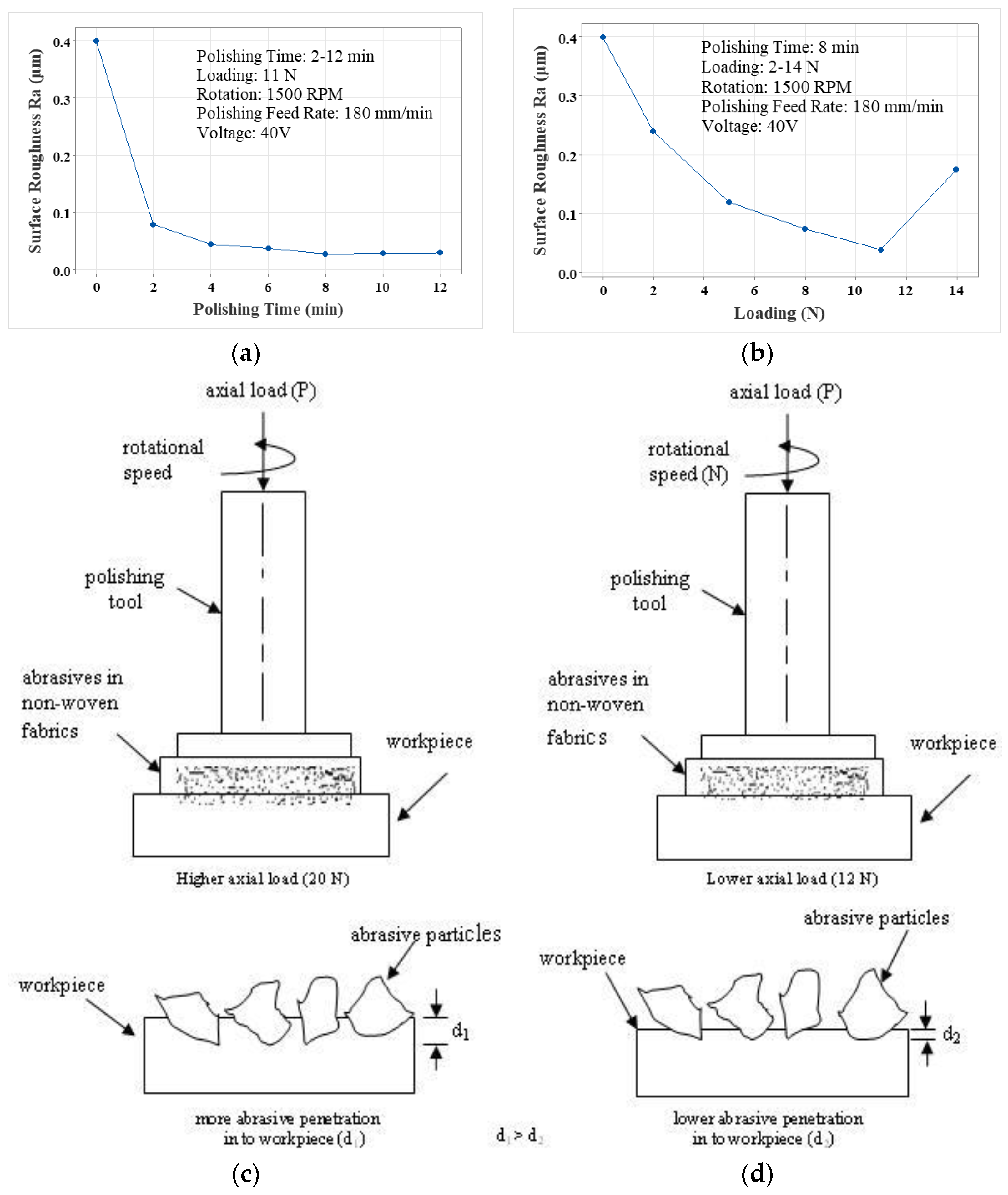
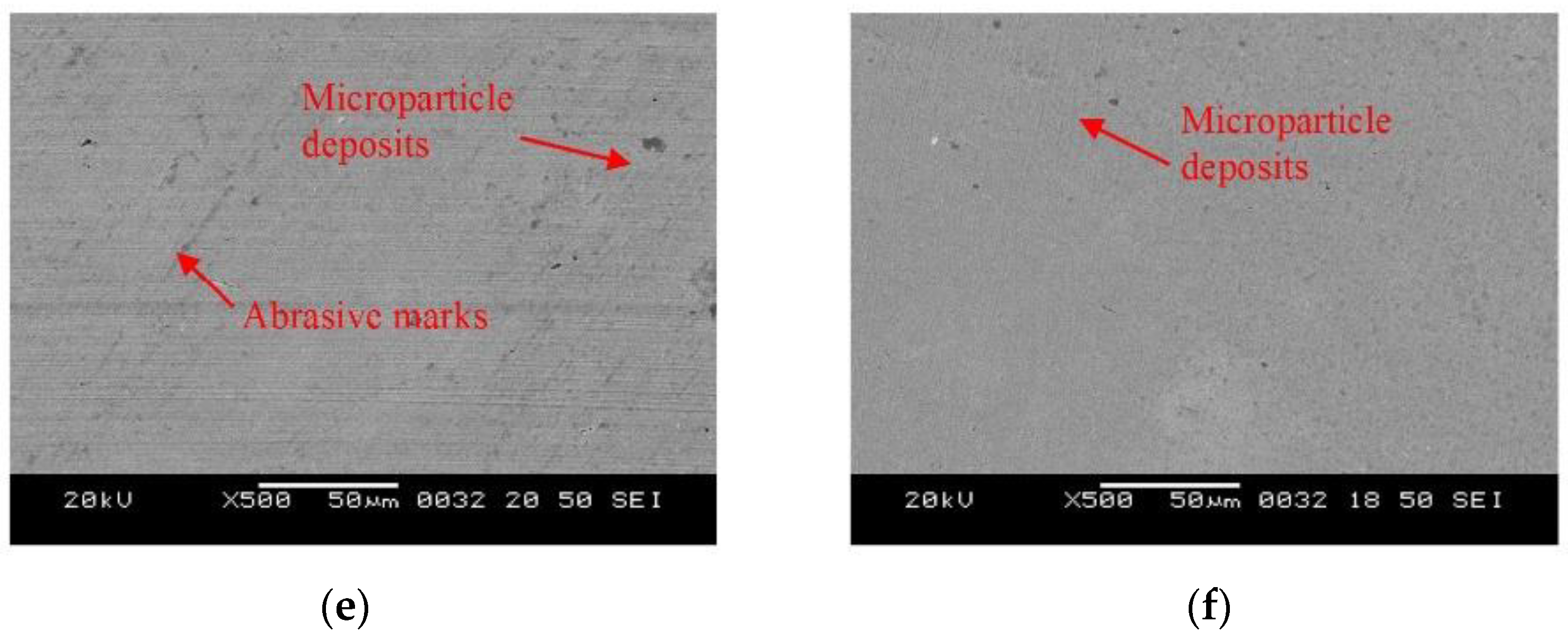
Figure 8.
3-D surface roughness Ra, surface profile and electron microscope photograph at 100X of (a) ground surface (b) after EPDAP(grit size=2000, axial load= 12 N, rotation speed= 1500 rpm, polishing time= 10 min) (c) after EPDAP (grit size=1500, axial load= 20 N, rotation speed= 800 rpm, polishing time= 10 min).
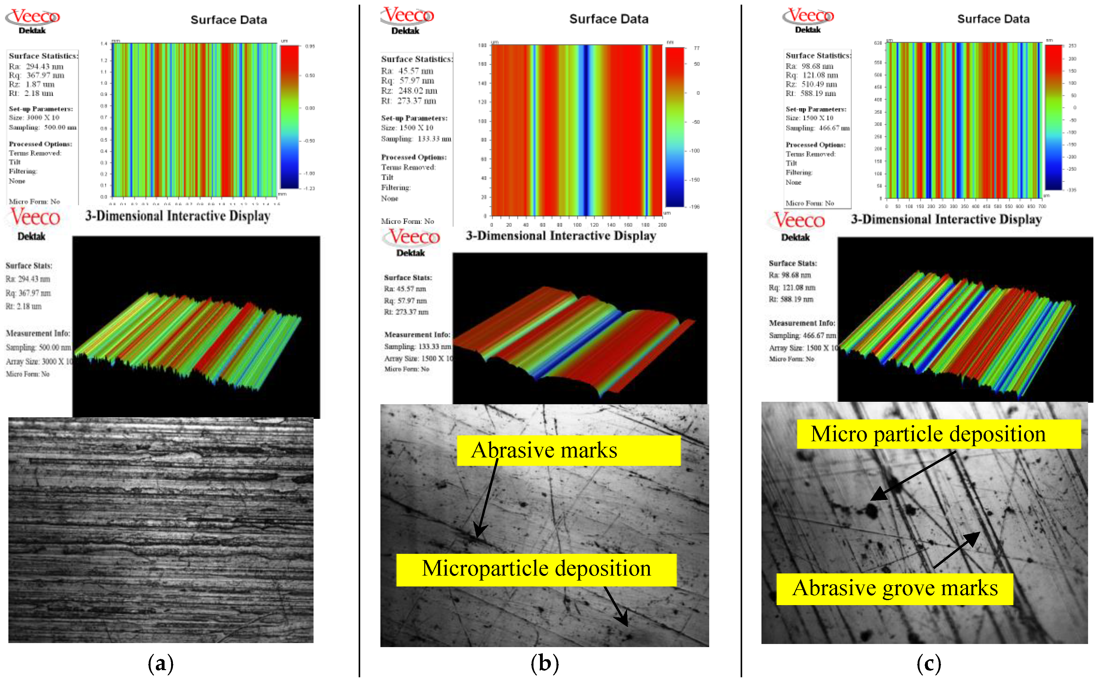
Figure 9.
Width and Depth of Groove Produced by (a) Grit 600 (b) Grit 1200 and at (c) lower axial loads (d) higher axial loads.
Figure 9.
Width and Depth of Groove Produced by (a) Grit 600 (b) Grit 1200 and at (c) lower axial loads (d) higher axial loads.
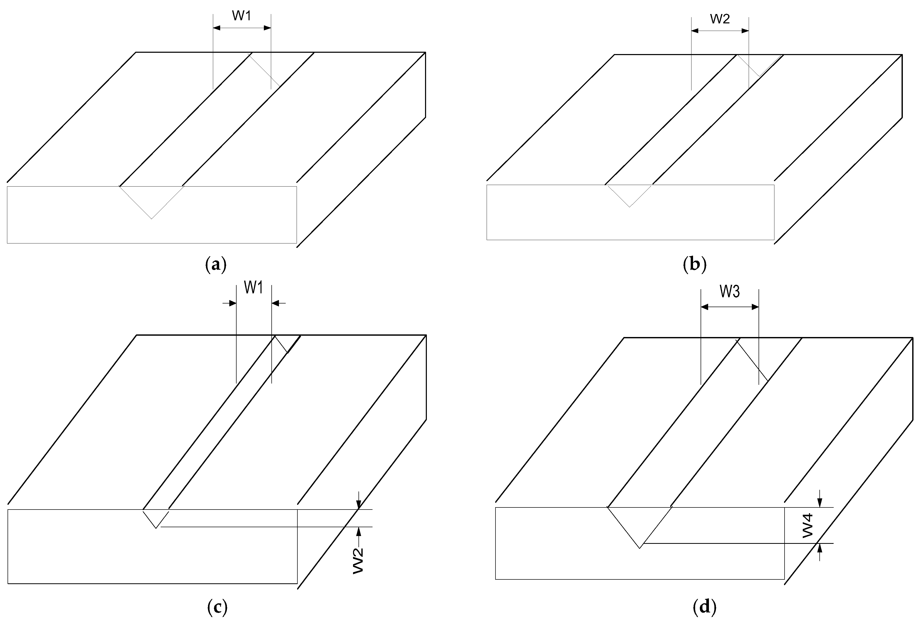
Figure 10.
2D Surface Profile, 3D Surface Texture and SEM of (a) unpolished (b) polished alumina ceramic surface at 5000X.
Figure 10.
2D Surface Profile, 3D Surface Texture and SEM of (a) unpolished (b) polished alumina ceramic surface at 5000X.
Disclaimer/Publisher’s Note: The statements, opinions and data contained in all publications are solely those of the individual author(s) and contributor(s) and not of MDPI and/or the editor(s). MDPI and/or the editor(s) disclaim responsibility for any injury to people or property resulting from any ideas, methods, instructions or products referred to in the content. |
© 2024 by the authors. Licensee MDPI, Basel, Switzerland. This article is an open access article distributed under the terms and conditions of the Creative Commons Attribution (CC BY) license (https://creativecommons.org/licenses/by/4.0/).
Copyright: This open access article is published under a Creative Commons CC BY 4.0 license, which permit the free download, distribution, and reuse, provided that the author and preprint are cited in any reuse.


