Preprint
Review

Advances in Corrosion of High-Temperature Materials: Interfacial Migration and Alloy Design Strategies

Altmetrics

Downloads

204

Views

163

Comments

0

A peer-reviewed article of this preprint also exists.

Submitted:

09 July 2024

Posted:

10 July 2024

You are already at the latest version

Alerts
Abstract
Structural and functional materials are subjected to harsh oxidizing environments that lead to a rapid decline in their surface chemical stability. At high-temperatures, the diffusion of atoms is erratic; thus, the reactive elements (REs) get a chance to migrate to the surface and look for oxygen-reactive sites. Their migration from the lattice sites creates vacancies in the matrix and thus weakens the bond, making the material prone to environmental degrading factors. Subsequently, the inward diffusion of oxygen, sulfur, nitrogen, or carbon may occupy these vacancies, resulting in undesired precipitation at the grain boundary, which is usually brittle. The solubility and dissociation of attacking species and corrosion products play the most critical role in corrosion in high-temperature water. To evade such situations, Ti, Al, and Cr are added in Ni/Fe-based alloys, forming a dense oxide layer on the surface that impedes further surface migration of ions. The stability of the alloys is then determined by the capability of these oxide layers to heal or reform during spalling/cracking. This review attempts to understand the migration of REs at the interfaces to prepare structural materials in any unexpected set of oxidizing service conditions. This review will also try to establish the interaction mechanism of REs novel/conventionally added in the alloys with the oxidizing elements in the environments to design better degradation-resistant high-temperature alloys.
Keywords: 
Subject: Engineering  -   Metallurgy and Metallurgical Engineering

1. Introduction

The English vernacular projects and insists on unalloyed pleasure and accentuate that the pleasure must be pure and not be unadulterated with other emotions [1]. Metallurgy rule-out this definition of pleasure, where pure metals barely find applications and their uses are too limited. Often metals are invited to alloy formation to obtain better and desired properties of interest. With the civilization journey of homo-sapiens, humanity began interacting with copper, gold, and tin in the form of metals. Alloying of Cu and tin yielded a metal yet stronger than Cu itself and initiated the era of the Bronze Age. Years later, the intimate mixing of Fe in activated charcoal resulted in a much stronger alloy [2], and the ancestor of steel was born. It was only due to the invention of steam engines; that hastened the bulk production of steel. Indeed, introducing alloying elements provides the desired property but also brings unavoidable issues. Very complex microstructures eventually degenerate during in-service conditions and grain boundary (GB) segregation [3] during high-temperature operation are a few critical issues.
In the modern era of civilization, life would have been hard to imagine without alloys: different alloy grades have captured the nooks and corners of human life. Conventional alloys perform satisfactorily to a temperature range of ̴ 873K–888K and pressure up to 25 MPa, but as soon as temperature enters an ultra-supercritical and advanced ultra-supercritical range [4,5,6,7,8], the performance of traditional high-temperature steels starts degrading drastically. The decrease in the performance and property can be attributed to the affinity of alloys and the alloying elements toward oxidation that corroded at higher temperatures [9]. The initiation of corrosion can adhere to various intriguing factors viz: stress-induced corrosion[10], crevice corrosion [11], pitting [12,13], erosion, hot corrosion[14], and erosion-corrosion [15,16,17].
The word “CORROSION” derives its birth from the Latin word “CORRODERE”, which means ‘gnaw away’. Chemically speaking, it can also be defined as the physiochemical interaction between a metal and its environment, which results in changes in the properties of the metal which may often lead to impairment of the function of the material, the environment, or the engineering system of which these form a part. All elements, alloys, and compounds have a love at first-sight for oxygen. Their propensity toward oxygen is even better at higher temperatures. Furthermore, structural and functional alloys of technological interest are inherently unstable. They get involved in oxidation and try to revert to their mineral form (considered the most stable form of elements). At higher temperatures, the diffusion of atoms is erratic and the reactive elements (REs) get a chance to migrate to the surface and look for oxygen-reactive sites. The change in the ratios of alloying elements due to migration from the lattice sites creates vacancies in the matrix and thus weakens the bond, as a result of oxidation causing a change in the near-surface microstructure making the material prone to environmental degrading factors. The presence of Al and or Cr inherently added to the alloys to form a stable oxide of Al2O3 or Cr2O3, respectively, acts as a barrier toward further oxidation of the alloys in harsh oxidizing environments [18]. The product of corrosion, thermodynamic rate, and the corrosion mechanism is a strong function of variables like environment, pressure, and temperature [19]. The spontaneous growth of the oxide layer on the surface kinetically governs this mechanism. The oxide layer stability is a matter of great concern considering the behavior of metals, especially in corrosive[20] and ultra-high temperatures (1100 °C) and pressure (200 bar) conditions [21,22]. The detachment of this oxide layer at very high temperatures makes the material end its life. Oxidation has remained the terrifying and undefeated warrior in the war of alloys against corrosion resistance at high temperatures. Almost all alloys get oxidized above a specific temperature leading to scaling, average percentage weight loss [23] (APWL) of material, and degradation in properties.

2. The Big Question

The big question is, why at all materials (metals and alloys) corrode? Is there any benefit to undergoing corrosion? What are the protective measures? Is it the alloying elements, chemical inhibitors [24,25], certain amino acids, and GBE [26,27,28,29,30,31,32], which can provide corrosion resistance even at very high-temperature?
This review deals with material degradation issues at high temperatures where corrosion is a fatal disease that weakens the material and degrades material performances, corrosion mechanism, and their protective measures to enjoy alloying at high temperatures. This review also attempts to understand the quantum charge transfer through the passive layers formed by the various oxide formers.
The very fact that very few metals like Gold (Au) and Platinum (Pt) which remains idle towards even the most potent reactive agents like aqua-regia [33], whilst other shows a strong affinity toward oxidation leading to corrosion at high-temperatures is a vindication that metals and alloys have a strong affinity for oxygen. Their affinity towards oxygen is justified by the fact that their atomic orbitals are incomplete. Metals exist either in its pure metallic form with the zero oxidation state or can be seen in partying with compounds with a central idea to lower their Gibbs free energy or to incomplete their vacant orbital and with variable positive oxidation state (often transition metals have varying oxidation states [34] due to incomplete d-orbital). In a real-world scenario, most metallic elements approach oxygen to form compounds, indicating a strong desire to achieve greater stability in their oxidized forms. For this apparent reason, to procure a metal in its pure metallic state from one of its compounds/ores, it is indispensable to put in energy. The vice-versa is also true; when a metal is exposed to its environment, it tends to emancipate this stored energy via the very profound processes of corrosion. This phenomenon of corrosion can be explained as an analogy to precisely what exactly happens with an object suspended at a point above the ground, which is equivalent to the metallic state with zero oxidation states. When allowed to fall freely to reach a stable state, it returns to a position of minimum energy on the ground which is equivalent to the metal’s oxidized state. In the oxidized states, metals are usually stable.

3. Corrosion Mechanism

To better understand the protective method of corrosion, one needs to know the reaction mechanism of corrosion. The chemistry that governs the corrosion mechanism is stimulated by redox reactions (a chemical reaction in which one element gets reduced, and at the other end, another element gets oxidized, hence the name: reduction-oxidation). The pre-requisites of such reactions are the co-existence of an element that is reduced (the oxidizing agent) and another that is oxidized (the metal). Thus, the overall reaction can be split into two partial reactions: reduction and oxidation, as shown in Figure 1.
At Cathode:
(Oxidant)/Mn+ + ne- →(Reductant)/M (Reduction Process)
At Anode:
(Reductant)/M →(Oxidant)/Mn+ + ne- (Oxidation Process)
In oxidation, the metal loses electrons, and the zone in which this happens is known as the anode (Figure 1). In the reduction side, the oxidizing agent captures the electrons that the metal has shed during the oxidations, and the zone in which this happens is the cathode. The heart of the corrosion protection methods lies in controlling the thermodynamical rate at which these reactions proceed. Conversely, corrosion rate can be slowed down by the increasing resistance of the oxide layer formed on the surface of metals and alloys and improving its strength, particularly in aqueous and high-temperature environments. The other method that can be deployed to curtail the corrosion mechanism is eliminating the possibility of redox reactions. If possible, conditions can be created to have only anodic or cathodic reactions, but these conditions are ideal and seem more or less a herculean task.

4. Why metal Diffuses Outwards and Oxygen Inward in the Alloy?

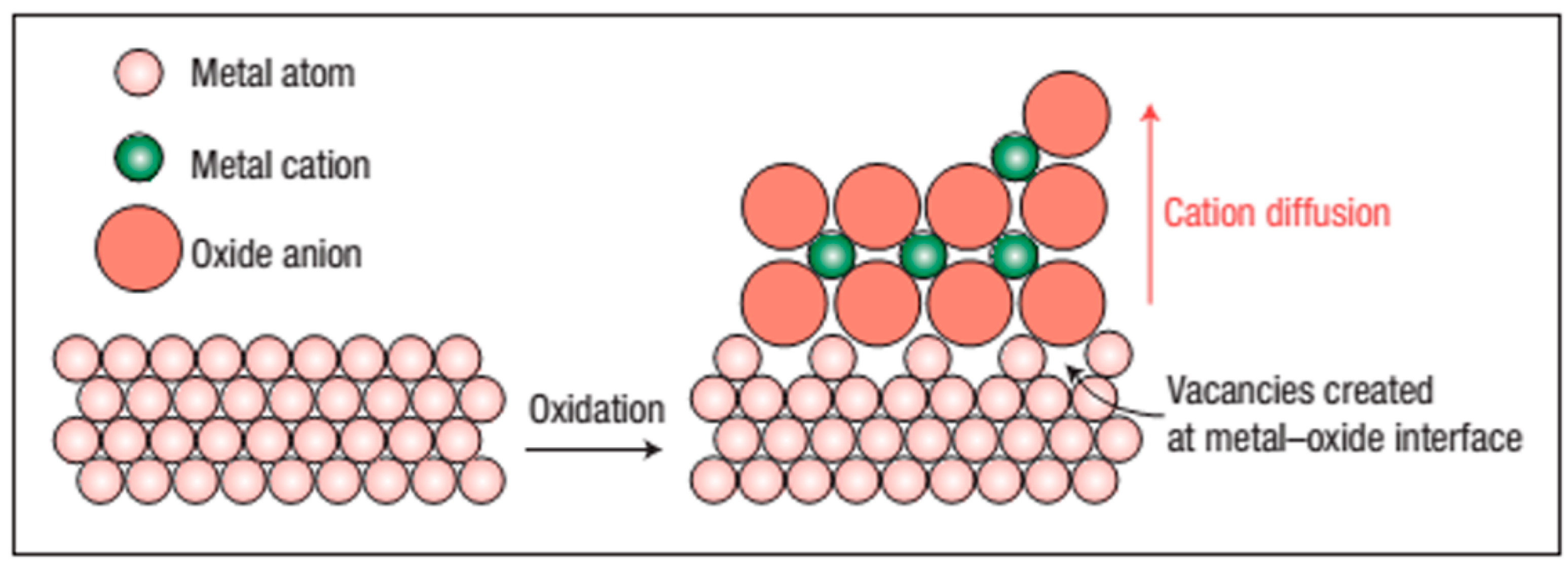
Metals in the alloy are appreciably smaller than their non-metallic counterparts. Their cationic nature makes them slightly more mobile than their peers and, therefore, helps in faster diffusion at the interface of an alloy/material. The metal ions move on the surface and have fewer nearest neighbors or coordination numbers [35] and as a result, have dangling bonds exposed to the surface, and in bulk, electrons move inside the material. Dangling bonds spread gloom over the surface and a state of high anxiety. These bonds must find ways to compensate for the apparent deficiencies by whatever chemical or physical means available to them. Suppose surface atoms do exist in a state of higher energy than the fully coordinated volume atoms. In that case, the metallic ions at the surface will have a higher propensity towards reaction than the bulk. This possibility is additionally backed by the fact that metals have more stored energy and want to stabilize them by forming oxides and hydroxides, in which they feel more stable by having negative Gibbs free energy [36,37,38]. Oxidation occurs first at the metal-environment interface resulting in the formation of a metal scale that acts as a barrier to restrict further oxidation. To sustain the oxidation process, either oxygen must diffuse inwards through the scale to the underlying metal or metal must diffuse outwards through the scale to the surface. Both transfers occur, but the outward diffusion of metal is generally much more rapid than the inward diffusion of oxygen (Figure 2) since the metal ions are appreciably smaller than the oxygen anion and move with much higher mobility.
The creation of vacancies at the metal-oxide interface in the high-temperature atmosphere becomes a responsible factor for the detachment of the protective oxide layer and causes a severe loss of material. Vacancies grow in size after considerable loss of material and often can be seen in many systems and are known by many names such as spalling failure in Fe-Cr-Al systems [39] and thermally grown oxide and bond-coat in thermal barrier coating (TBC) systems [40,41,42] and can often be seen by various characterization techniques, for instance, SEM and TEM. In the case of materials deployed in high-temperature in-service conditions, the protective oxide layer degenerates and falls off, and it is now evident that the interface has failed completely.

5. Quantum Approach in Understanding the Electron Transfer at Passive Interfaces

Electron transfer (ET) is a perfect vehicle for developing the theory of corrosion science and understanding the corrosion control parameters owing to its simplicity of reaction dynamics [43]. It is often critical to understand the corrosion mechanism in layers passivated by corrosion-protecting elements and material, for instance: Cr, Al, Ti, Mo, and W, etc. Several efforts have been attempted using the first principle to understand and predict the reaction rates, but they turned to be futile. However, the seminal work of Gurney [44] on quantum electron transport (QET) theory was the first unassailable attempt to understand the corrosion mechanism and bring the brighter side of Tafel’s law (an exponential dependence of charge transfer to the applied potential). Tafel’s law, even after 100 years, has still maintained its importance and is vindicated by its vivid use in electrochemistry [45], corrosion science[46], and energy devices [47]. In addition to Tafel’s law, inverse Tafel’s law is also a strong tool for understanding the dynamics of oxide layer formation on the metal surface. The formation of this oxide layer further resists corrosion by forming a passivation layer on the metal surface during its exposition to high-temperature and environmental conditions. The Tafel equation must be introduced to understand the passive layer's electron transfer and corrosion mechanism. Tafel formulated his famous equation connecting the overpotential (η) and the current density (j) by the equation given below:
η= a+ b log (j); where a and b are constants [48] and bears relationship as a = b ln (jo) and b = RT/zαF; (R: universal gas constant, T: temperature in Kelvin, F: Faraday’s constant, z: charge number, jo: exchange current density, and α: is transfer coefficient). The parameters a and b are now commonly known as Tafel’s slope. The nomenclature of an equation in the name of its inventor is quite common, but having a slope in one’s name is rare and remarkable.
This seminal equation was initially applied to the charge transfer reactions occurring under controlled conditions and had nothing to do with the corrosion mechanism whatsoever. Over the period, people used this equation in the entire field wherever electrochemistry was applied. To quote a few lines from the special issue on the centenary of the first publication of Tafel’s equation: Tafel’s equation is not only a remarkable achievement but a remarkable equation itself [49].
According to the QET, transferring an electron or a charge between two states of energy is only feasible when both energy levels are nearly equal. This transfer can be made possible by supplying energy to the molecule. Marcus[50,51,52,53] describes only a small possibility of electronic orbital’s overlap in the activated complex, and often, the electron transfer mechanism should proceed via a “slight-overlap” mechanism. Greater detail of the Marcus mode is discussed elsewhere[54]. According to the classical electron transport theory, the amount of current flowing (i) in any redox reaction where QET is occurring is given by:
i α n E , V N E , d P E , d d E d x ; (n(E,V): electron density with energy E at the applied voltage V, N(E, d): acceptor species number having energy E at a distance d from the metal surface, P(E, d): the probability of tunnelling electron from the metal to the acceptor.
The following assumptions have been undertaken to formulate the above equation: (1) the electric field inside the passive layer bears a linear relationship with the applied potential, (2) defects inside the matrix is constant, (3) the oxide film is homogenous and consists of a single-phase, and (4) thickness of the passive layer is independent of applied potentials. As developed by Schmickler and group [55], this theory is based on the ideal conditions, which are hard to meet in superalloys and materials of interest. Metals, alloys, and materials of high-temperature interest often violate these ideal assumptions. Hence, better formalism has to be adopted to understand the current flow or charge transfer via passive layers to control the menacing corrosion. In a practical scenario, the electric field intensity (ε) is a function of distance (l), and varies with the applied potential (V) is given by:
ε = V/l
This simple expression explains the decrease in ε when the passive layers thicken over time. The thick passive layers resist further migration of cations from the bulk through the lattice to seek oxygen from the surface. Verwey introduced a temperature-dependent model known as the high field model (HFM) to explain the electron transfer through the passive layer to match the real-world scenario and formulated an anon-linear equation:
i = A   e x p ( B ε ) ; (i: current density, A and B are temperature-dependent constants.
This model assumes that the charge motion within the oxide layers acting as a potential barrier is the rate-determining step. For sufficiently high fields and cations conduction current is given by:
i = 2 a C v e x p [ W z F a ε / R T ] ; (a: half-jump distance, C: ion concentration, v: vibration frequency of charge, W: activation energy, z: ionic charge, F: Faraday’s constant, R and T are universal gas and temperature in Kelvin respectively).
The outcome of this equation fails to satisfactorily satisfy the experimental findings of the steady-state achievements of film thickness or current, and once again, this theory was discarded, yet another new model proposed by Macdonald’s point defect model (PDM). This theory assumes that in steady-state, passive films, ε is independent of the position of the film in the matrix. This finding has its root in high ε > 2×10⁶ V m-1, which is sufficiently high and close to dielectric strength enabling the creation of holes-electrons sufficiently enough to buffer the medium against any rise or fall in the potential gradient [56]. PDM, like HFM, also suggested a decrease in current density due to increased film thickness at the interface but no change in the field strength. From an electronic standpoint, the passives films are analogous to a highly doped metal/n+ -i-p+/ solution junction. Depending upon the relative concentrations of donor oxygen/anion and acceptor/cation vacancies, the width of the passive layer increase with the increase in applied potential, maintaining a constant potential gradient. This model resembles the resonance tunnel diode (RTD) [57] and exhibits negative temperature coefficient characteristics. This model is in close approximation to the experimental condition such that at the higher temperature, the passive layers become weaker due to the tendency of the locked charges to conduct electricity, demonstrating the negative temperature coefficient characteristics. In reality, passivation helps gradually increase oxidation resistance until a certain temperature range. The layer breaks via a spalling failure mechanism at a specific threshold temperature (depending upon individual alloys). The resonance tunneling of charges or electrons proves to be more promising than direct tunneling. The quantum mechanistic approach says there is always a possibility and indeed a probability of an electron being tunneling through any potential, however large enough to confine it and restrict it from crossing; it is only a matter of time. Schmickler and Ulstrup [58] postulated a two-electron coherent tunneling theory for metal oxide films. This two-electron transfer mechanism and RTD can conjointly help to understand the diffusion of charge through passive layers.
Another aspect of the quantum theory deals with this barrier layer as a defective structure containing a high volume of point defects. The oxygen being donor and metal cations acting as an acceptor resembles an electrolytic cell with redox reaction feasibility in superalloys with Cr, Ni, and Fe being cations and diffused or ambient oxygen forming a complete cell.

6. Metallic Additions in Alloys to Scale Up the Corrosion Resistance

The addition of alloying elements either during alloy formations or coating of corrosion-resistant elements [59] on precious alloys has been a trend toward protection and increasing the longevity of high-performance material. Certain alloys are tailor-made to operate above 923 K and pressure of 25 MPa or even more and are commonly known as superalloys. The operating temperature of these alloys are raised to increase energy efficiency and scale back CO2 emissions in one go in nuclear and thermal power plants, turbines blades where massive thrust is experienced, jet engines to improve their performances, chemical industries owing to its corrosion resistance, photochemical industries, and in tools and dies for extremely hot working sections of metals, etc. These entire domains require corrosion resistance elements to be inherently alloyed during the alloy formation. To meet these challenges, several class of materials are explored, however, only Ni-based superalloys have shown potentials to meet these criteria [60].
Superalloys are multi-alloyed elements; hence, their reaction with oxygen can be expected to be very complex sometimes [61]. However, these alloys are developed to achieve resistance to oxidation by utilizing the concept of selective oxidation [62]. Eventually, the oxidation processes in superalloys are not as complex as one might initially presume. The selective oxidation phenomenon in superalloys to obtain oxidation resistance involves oxidizing essentially only one element in the superalloys and trusting upon this element’s oxide for protection. For the feasibility of this process, the oxide layer formed must perfectly cover the entire surface of the alloy and it is essentially this oxide layer through which diffusion of the reactants (i.e., the element being oxidized selectively and oxygen) takes place at comparatively slow rates. The elements which satisfy these conditions are very few. The only elements are silicon, aluminum, titanium, and chromium. The presence of silicon at a sufficient level to allow selective oxidation conflicts with the high melting point requirements of superalloys and hence silicon is discarded in favor of selective oxidation for oxidation resistance. The available techniques to induce selective oxidation at lower concentrations are reported in the literature [63,64]. Singh et al. report the presence of silicon intermetallic compounds in high-temperature superalloy 617, but its origin in the matrix and its functionality are still under investigation [6]. Superalloys with Ni, Co, and Fe utilize the elements Cr or Al for selective oxidation and are often referred to as Cr2O3 and Al2O3 formers and act as a guard against oxidation degradation [6]. The successful selective oxidation process depends upon the phases which need to be selectively oxidized, and they must have the elements to be selectively oxidized at a concentration sufficient enough to form scales of Cr2O3 and Al2O3 to form on alloy and phases which do not contain these are preferentially attacked at high-temperatures. Nair et al.[65] have reported an increase in corrosion resistance of Al0.1CoCrFeNi high entropy alloy (HEA). The HEAs are a special class of alloys that has equiatomic combinations of 5 or more elements[66]. These HEAs are finding wider applications in almost all energy conversion/storage systems, due to their tailor made physical properties to suit a particular task [67,68]. These HEAs offer a wider space for chemical combinations from the periodic table, allowing the entropic contribution to overcome the enthalpic contribution and stabilizing the solid solution [69]. These HEAs are better suited to corrosion and offer a greater resistance by bringing passive film stability [70]. A study primarily composed of aluminum (Al), cobalt (Co), chromium (Cr), iron (Fe), and nickel (Ni), commonly referred to as Al(Co)CrFeNi HEAs has been carried out by Ulrike Hecht group [71]. The corrosion activity of this material is investigated in 3.5 % NaCl solution. The results indicate that the minor addition of Mo can dramatically influence the corrosion resistance of this alloy by restricting the pit formation [72]. It is also found that the FCC phase in equimolar Al(Co)CrFeNi is more resistant toward corrosion, demonstrating more noble corrosion potential. In addition, lower corrosion current density and corrosion rate than BCC phase counterpart is an additional benefit. Though the exact mechanism of corrosion prevention of Mo in presence of Cr in steels is still unestablished, it is believed that both Mo and Cr form a barrier against Cl ions [73]. Mo has an ability to form Mo-oxo-chlro a stable and soluble complex along with insoluble chlorides and oxide chlorides on the surface of the steel, thereby preventing the corrosion. Critically, the ratio of Al/Cr plays another dominant role in corrosion inhibition in this alloy. Corrosion resistance in high-temperature alloys can be further improved by the addition of W due to their improved mechanical properties. In another study on the role of HEAs coating (HEACs) using different composition of Mo in FeNiCoCrMox (x= 0, 0.15, 0.20, 0.25) on 316 grade stainless steel (SS) brought some interesting results [74]. The microhardness increased in the order of 70.1% (Mo0), 77.0% (Mo0.15), 84.9% (Mo0.20) and 90.5% (Mo0.25) is shown in Figure 3a. The average friction coefficient of Mo0.25 is among the lowest indicating that it has best wear resistance (Figure 3b). The wear rates decreased dramatically in the order Mo0.15 (11.1%), Mo0.20 (27.8%), Mo0.25 (38.9%) w.r.to Mo0 is shown in Figure 3c. The results of the electrochemical tests indicated that HEACs exhibited intergranular corrosion as their predominant type of corrosion, and all HEACs demonstrated superior corrosion resistance compared to both 304 SS and 316 SS. Notably, among the HEAC samples, Mo0.20 HEACs exhibited the highest level of corrosion resistance, which can be attributed to the beneficial influence of MoO3 on the formation of a protective Cr2O3 passivation film. The increase in hardness for Mo0.25 is due to solid solution strengthening offered by Mo. Rodriguez et al. investigated the corrosion effect of Mo addition to CoCrFeNi2and CoCrFeNi2Mo0.25 under 3.5 wt% NaCl [73]. The cathodic current density, as obtained by the polarization curve, shows a straight-line indicating control over electron transfer. The presence of Mo in the alloy makes a passivation layer and offers a high electron transfer resistance. Mo also offers transpassivity by getting oxidized at higher potentials [75]. The presence of Cr in the alloys undoubtedly offers the first guard against corrosion, but the addition of Mo provides stability to the protective layer prepared by the Cr. In addition to this, Mo also interacts with S in the alloys and provides global repairment to the local weak spots [76]. The presence of Mo in the alloys also administers the small potential difference between re-passivation potentials (Erep) and breakdown potential (Ebre) offering resistant to corrosive environments and protects the material from pitting corrosion in NaCl solution.
As an alloying elements, Aluminum (Al) always plays dominant positive role in corrosion inhibition in high-temperature alloys. Al is thus regarded as another vital metal addition that significantly changes the corrosion properties of the alloys. In the presence of oxygen, Al tends to combine with it to form alumina. Once there is a sufficient amount of Al, alumina acts as a protective barrier, preventing the permeation and penetration of carbon. However, when the Al content is relatively low, a situation arises where an excess segregation of the Al-rich and Cr-rich phases occurs. This excessive segregation ultimately leads to a deterioration in corrosion resistance. Thus, its study become essential to understand the protection mechanism. Recently, the role of Al addition in a series of Alx(TiZrHfNb)100-x (x= 0, 3, 5, 7, 12 at%) refractory HEA (RHEA) was investigated [77]. The addition of Al significantly improves the mechanical properties of the alloys. It was found that the addition of Al brings a more compact BCC structure to the alloys. The YS results indicate that YS-Al bear a liner relationship (Figure 3d). YS for Al-0% is 331.3 MPa, while for Al-12%, it jumps by 3.3 times (1097.8 MPa). The results of wear rate and Vickers hardness of RHEA with varying composition of Al is shown in Figure 3e. It is but obvious that with the increase in Al content, hardness values increase and wear resistance improves reflecting in lower wear rate. The gradual increase in hardness is due to significant localized lattice distortion arising from the atomic size difference between the various components, which bring improved solution hardening. It is evident that atomic radii of Al are similar to Nb and Ti, but it significantly smaller than that of Hf and Zr. Since the δ values for Al-0% to Al-12% alloys are 5.733, 5.794, 5.830, 5.863, and 5.929, respectively are less than 6.6, indicating that the current BCC phase is essentially a disordered solid solution alloy. Eventually, the increasing δ values marks an increase in hardness trend, and the strong bonds between Al and the constituent transition metals also contribute significantly to the hardening effect in compliance with previous report [78]. Therefore, the excellent hardness can be attributed to both the strong lattice distortion and the robust bonds between Al and the alloy constituents. Similarly, to reveal the oxidation behaviour of alloys, normally a power law is used ( m = k 1 t n ); here Δm is mass gain/area, k1 is oxidation rate constant, t is exposure time (s), and n is time exponents. The oxidation data for this alloy is shown in in Figure 3f. The n values for different Al doping wt% are Al-5% (0.91), Al-7% (0.85), and Al-12% (0.78). As n values lies between/above 0.5 (n <0.5: parabolic) and less than/approaching close to 1 (n= 1: linear), which indicates that oxidation behaviour of this alloy is in between parabolic and linear. As Al-12% display a minimum oxidation rate, reflecting the wear mechanism to be oxidative at elevated temperature for this alloy.
Yet, another attempt by Kim’s group[79] to study the effect of Cu addition in virgin Al ingot alloy comprising varying wt % of Cu in an artificial acid rain environment containing 200 ppm of Cl ions are made. The results obtained by ToF-SIMS with the low Cu concentrations (0.005, 0.01, 0.03 wt% Cu) reveals that only 0.03 wt% Cu with Al gives reliable information and in the rest of the composition either the intensity is very low (0.01 wt% Cu), or it was difficult to detect in case of 0.005 wt % Cu. The detection of Cu on the Al surface is indicated by the intermetallic Al2Cu phase and has been supported by various research groups too [80]. It is believed that the higher Cu concentration causes more precipitation of Al2Cu phase[81] and increases the cathodic current density owing to its higher electron transfer in 0.03 wt% Cu. The high cathodic current density of 0.03 wt% Cu is a clear indication that pitting corrosion will be dominant in the matrix and Al with this composition of Cu has the least corrosion resistance. Thus, care must be taken while alloying addition of Cu to high-temperature material, and wt% must be controlled around 0.01 wt%.Yan et al.[82] studied the effect of alloying elements on corrosion behavior in Co–Al–W material. Adding the elements, for instance, Cr, Si, and Al to this alloy improved the corrosion resistance of this alloy. The order in which these oxide resists oxidation is given in decreasing order:10Cr > 20Fe > 1- Si > 2Ta > Base > 20Ni > 2Ti > 2Mo > 2V > 6Ni–4V. The possible mechanism of oxidation protection is the formation of three types of oxides of CoO at high temperature. Firstly, the formation of a stable cubic rock types CoO above 1173 K with a lattice constant of 4.26 Å[83]. Spinel-type Co3O4 with a lattice constant of 8.15 Å [84] and in other cases a thermodynamically unstable oxide Co2O3 also forms under controlled conditions [85]. The Co3O4oxidewasthefirst to be formed on the outer surface of the alloy; the inward diffusion of oxygen forms it, and the rich content of Co in the alloy favors the upward diffusion of Co to form stable Co3O4. The decrease in the partial pressure of oxygen and the depletion of Co from the base metal initiated the formation of the second layer of the defensive mechanism by Al2O3.The continuous formation of Al2O3 depletes the percentage of Al locally and helps in initiating the precipitations of Co3W. This reduction in major alloying elements promotes the porous type layered structures, and hence coarsening is avoided or impeded, and therefore only fine-grained structures are present. The presence of fine grain structures helps in strengthening the material at high-temperature. A substantial reduction in the partial pressure of oxygen induces the formation of CrO2 but this oxide becomes thermodynamically unstable.
The presence of Cr in the alloys acts as an oxygen getter and further inhibits oxygen diffusion into alloys. Mo and W also offer selective oxidation by acting as an oxygen getter and cause the diffusion of Al in alloys to decrease considerably. In this way, the presence of Cr, Al, Mo, and W along with the presence of some oxide particles helps in promoting the selective oxidations process and preserves a considerable number of precious alloys operating at very high temperatures.

7. Role of Texture Control and Surface Energy in Corrosion Inhibition

Microstructural texture in alloys plays a significant role in determining the physical properties of the alloys during their service conditions. Surface textures in metal and alloys are introduced during the mechanical deformation or the processing of the material for instance: forging, rolling and drawing, and it brings significant changes to their physical properties including wear and friction properties. The corrosion resistance of material exhibits a strong relationship with crystallographic orientation and crystallite interfaces at the weld junctions [86,87]. Thus, it becomes imperative to understand precisely the role of texture in corrosion control. There is yet another important factor that plays a significant role in controlling the corrosion of alloys at high-temperature is surface energy. It is established that the activation energy required for the dissolution of the densely packed surface is relatively higher than that of the loosely packed surface. However, opposite rule governs the surface energy, where a densely packed surface has lower surface energy (SE) than that of a loosely packed surface [86]. Benefitting from these two established facts, the high-temperature alloys are designed to have low surface energy to obstruct corrosion for a longer time. It becomes even more important when materials are joined together via welding. Often a stress gradient is generated at the interface of base and weld metal which later during service condition becomes an active site for corrosion-induced failure. Primitive study on steel found that the carbon-steel texture changes after corrosive and wear resistance tests[88]. The orientation density function (ODF) of the alloy showed different trends under the same applied stress of 9.6 N to corrosive and wear tests in corrosive environments. It was noticed that Goss and brass texture in corrosion wear situations completely disappeared contrary to the dry wear test environments. The difference in the ODF is ascribed to the presence of reduced formation of shear/friction forces in the presence of NaCl which acts as a lubricant. It was further found that weight loss in the case of corrosive test was much lower as compared to dry wear corrosion tests, the reason being again the lubricating effect of NaCl. In another study, it was found that sulfide stress corrosion cracking (SSCC) and strain rate tests bear a close relationship with the surface texture. Here, it is required to mention that there are certain favorable planes for dislocations motion during crack initiation and crack propagation arising due to SSCC/hydrogen-induced cracking (HIC) often encountered in high-temperature alloys. Thus, it is required that the easy motion of these favorable planes should be restricted during the crack initiations. Failure arising from the SSCC includes two steps: crack initiation and crack propagation, dependent upon the crystallographic texture[89]. The crack propagations and crack initiation follows the following orders of planes (100) > (110)> (111) and (110) > (100) > (111), respectively [90]. In addition to this, surface normal to transverse direction (TD) having family of planes (552) has more corrosion resistant potential and lowest corrosion rate compared to the other two directions namely rolling and normal direction abbreviated as (RD) and (ND), respectively. The improved corrosion resistance is shared partially to grain boundaries (GBs) and texture effects. The importance of texture was once again established from the study carried out on steels alloyed with Sb and Cu in extremely corrosive environments of pH 0.3 having % vol fraction of H2SO4 and HCl in 16.9 and 0.35, respectively [91]. A comparison of hot and cold rolled steels showed that preferential orientation of planes with {111} along with {101} and {001} remain dominated opposed to {001} dominated planes along with {101} and {111} in cold rolled. The low corrosion resistance of cold rolled steels along the direction {100} is ascribed to its high surface energy thus favors faster dissolution of atoms.
It should be understood that cold rolling during the alloy processing brings deformations twins and dislocation arrays inside the alloys, which are known as one-dimension crystals defects. The presence of crystal defects inside the matrix allows faster diffusion of Cr/Mo and allows easier carbide nucleation assisted by a low free energy barrier. These easier diffusions and nucleation act as different phase formations than the matrix and introduce stain inside the material matrix inside. During external stress, these sites act as preferential sites for crack initiation, leading to material catastrophic failure.
The other factor that significantly controls the corrosion resistance of a material is surface energy and the associated phenomenon which needs to be addressed is hydrophobicity. It is the hydrophobicity that does not allow water to stay for longer durations on the metal surfaces by reducing the metal-water contact area and thus protecting the material from corrosion. For corrosion protection in high-temperature, the surface must have minimum contact with the corrosive environments.
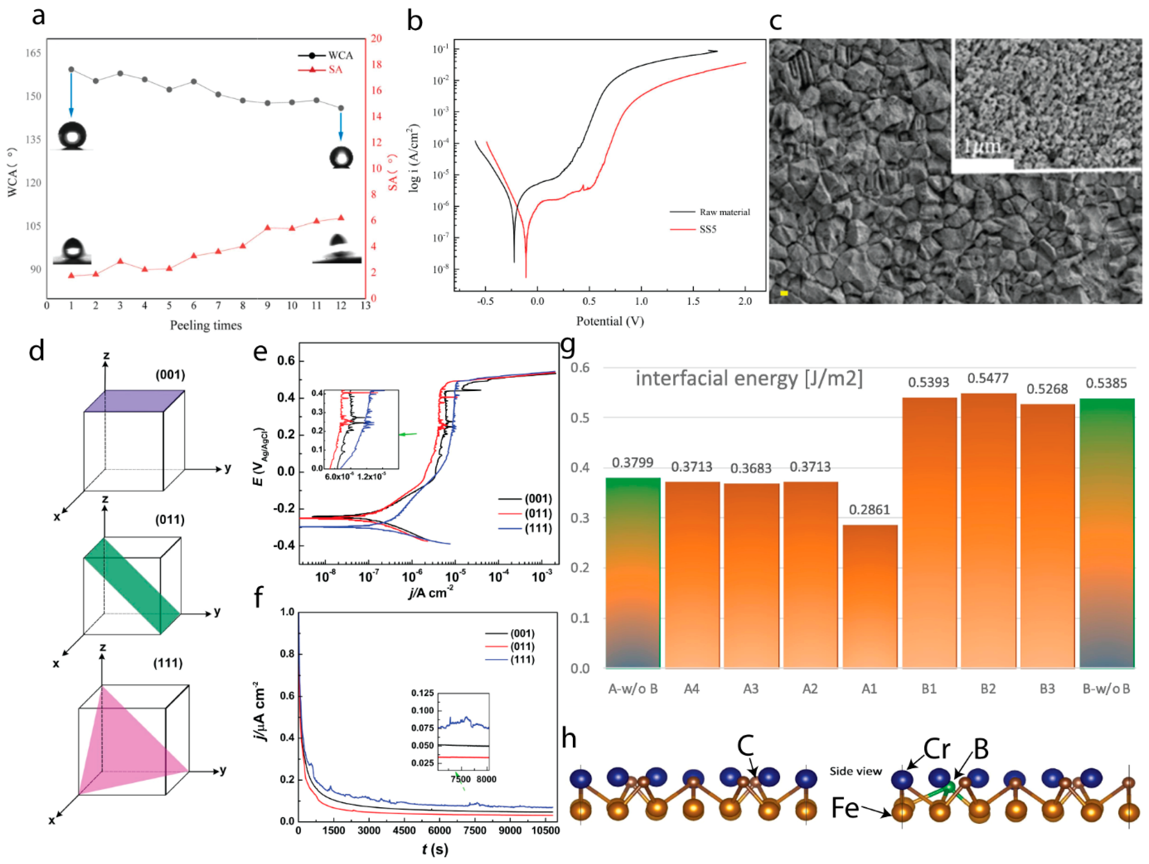
In a study carried out on 316 SS, a super-hydrophobic (SHP) surface was achieved through a novel one-step simultaneous H2O2, acid (HF) etching, and perfluorooctyl trichlorosilane (PFOS) modification significantly improved the corrosion properties of the material [92]. This study accounted several factors, such as, varying the molar ratio of H2O2/HF, reaction time, and mass ratio of PFOS/HF that could influence the hydrophobic surface. As a result, a maximum water contact angle (WCA) and a minimum slip angle of 161.78° and 1.94°, respectively are achieved (Figure 4a). Though a downward and upward trend was observed with an increase in peeling time for WCA and SA, respectively, it was much better than several other techniques reported earlier [93]. To reveal its corrosion properties, polarization curves were obtained against bare SS (Figure 4b). The result of corrosion inhibition rate for SHP-SS was much higher as 83.5% against some of the most complicated techniques reported earlier [94]. The corrosion inhibition parameters such as corrosion potential (Ecorr: V), current (icorr: A cm-2), and the corrosion rate (Vcorr: mm/A) for bare SS/SHP-SS are -0.2265/-0.1088, 2.400×10⁻⁶/3.965×10−7, and 2.805×10⁻²/4.652×10−3, respectively. These values indicate that the corrosion resistance of SHP-SS is remarkably improved. The excellent SHP 316 SS is attributed to the creation of a micro-nano structure achieved through acid etching, coupled with the successful grafting of PFOS onto the metal surface with the assistance of H2O2 (Figure 4c). Furthermore, this hydrophobicity of SS was maintained even after 3 months of continuous exposure to the ambient air.
Corrosion protection through the hydrophobic surfaces can be understood in terms of trapping air inside their structures due to their hierarchical structures that allow them to put a restriction on the corrosive elements/ions to directly interact with the alloy surfaces [95]. Another aspect to understand corrosion protection of hydrophobic surfaces stands on the development of Laplace pressure built on the superhydrophobic surfaces having contact angle > 150°.
The role of crystal planes in corrosion control can’t be ignored in alloys operating at high-temperature. Recently, a study conducted upon DD5 (a Ni-based single crystal) on different crystal planes indicate that corrosion rate follows the order (011) < (001) < (111) with the passive films grows faster and denser on the planes having higher surface energy [96]. The enhance performance of (011) plane is ascribed to the presence of Cr2O3 and enrichment of MoO3 in the passive layer that improves the corrosion resistance. Before moving further, it is essential to mention here that in metal and alloys, the corrosion behavior is dependent upon the orientation of the crystal planes with a simple, straightforward chemistry but this could be more complex in Ni-based superalloys, particularly with the passive nature of films and often dozens of alloying elements. Furthermore, the passive behavior varying with different planes make the corrosion analysis even further complex as has been reported in superalloy 738 [97]. This complex behavior is due to various proportions of Cr2O3, TiO2, and Ni(OH)2 passive films on differently oriented surfaces inside the alloy. Coming back to the results and discussions on DD5 superalloy with its three crystal planes (Figure 4d). The polarization curves indicate that current densities of all the planes rapidly increases initially reflecting the active dissolution of the surfaces (Figure 4e). However, current gradually declined as the potential went up, due to the formation of passive films. A smaller current (inset) value reflects better corrosion property of (011). Additional polarization plot of current vs. testing time (s) exhibit a smoother (Figure 4f and inset) current profile for (001) and (011) planes compared to (111). Here the current spikes show the pitting corrosion event occurs on the planes due to localized passive layer breakdown and repassivation of the active sites on the alloy surfaces. Evidently, the (111) surface with more current spike is more prone to corrosion than other two. It is conclusive now, that the barrier layer growth is more facile on planes with highest surface energy and lowest atomic packing density while closed packed plane (111) has lowest protection ability. Interfacial energy of the plane can also be tuned by external doping such as boron, aluminum, silicon, and so on in trace amounts. In a recent study, boron substitution was made in a FCC Fe (001)/Cr23C6 (001) to alter the interfacial strength of precipitate and the matrix (Boron substitution induced FCC Fe/Cr23C6 interfacial strengthening: An ab initio study). DFT calculations reveal that boron substitution has significant impact on the interfacial energy and the atomic arrangements at the interface by bringing increased covalent bonding. The increased covalency ensures more ordered structures at the interface thereby making the diffusion process less favorable energetically. Eventually, precipitates like NbC, Cr23C6, other phases like sigma and μ-phases, and other microstructural evolutions are greatly affected which play a dominant role during creep activities. A reduction in the interfacial energy by (~0.09 J m−2) after boron doping (0.29 J m−2) at the interface of matrix and precipitate play a dominant role in creep retardation and improving interfacial strengthening. Several sites were selected and the results obtained in Figure 4g, clearly indicates that interface energy optimization is crucial for alloy design and optimizations. The intentional addition of boron at A-terminated Cr23C6 sites significantly reduces the interfacial energy from 0.38 to 0.29 J m−2. To make a clear of such difference in the interfacial energy it is necessary to consider the local arrangements. The side view of the most symmetrical (001) interface between FCC Fe and Cr23C6 sites is shown here (Figure 4h). Fe atoms have a covalent bonding with C and mostly metallic with Fe/Cr are projected onto Cr-C sublattice. These mixed interface allows a significant charge transfer Fe to C-atoms. With B-doping, a short range interface strengthening is manifested and a strong covalent bonding is established between Fe-B and thus stabilizing the interface disordering. Though this study brings several insights on the doping boron to stabilize the interface, extension to this studies considering different layers (2nd, 3rd, 4th, and so on) could be an exciting filed and can bring wealth of novel information.

8. Atomistic Study of Corrosion

In this section, detailed insights on the corrosion mechanism are presented bringing the atomic level into considerations. A clear picture of corrosion and its initiation in its very early stage of triggering will not only help us in understanding the corrosion propagation over time but can also assist in bringing delayed corrosion by applying pre-measures and controls to metal and alloys surfaces. Often, metal surfaces are coated with thin layers of protective oxide layers or may be found coated with inorganic/organic coated layer that continually interacts with the aggressive/corrosive environments [99]. This section will focus on the interaction of the surfaces with the aqueous environments. To know more detailed aspects of the corrosion mechanism, it’s modelling and various methods the readers are requested to ref. [99,100,101].
When metal surfaces are exposed to aqueous corrosive environments, the polarized metal environments cause water dissociations leading to the formation of OH ions. These sporadic oxide ions start vehemently reacting with metal atoms and in the process, metal/water interface is modified completely resulting in the formation of the passive anodic oxide layer. Here we will discuss the interactions of these OH- ions w. r. to Ni surface as most of the high-temperature alloys are made up of Ni-based or at least contain Ni as a dominant element. On the Ni, the oxide surface also has a faceted structure similar to those obtained on Cu [102] and Ag surfaces. This faceted structure indicates that there exists a slightly tilted epitaxy between the preventive oxide layers of NiO and Ni (111) lattice. The tilt between Ni(111) and NiO surface has been measured to be about 3.3°[103]. Interestingly the NiO (111) [1-10] grows with an antiparallel epitaxy on the Ni (111) [-110] substrate. A hexagonal terrace type lattice with 0.3±0.02 nm is grown on the interface of NiO and Ni substrate [104,105]. The density functional theory (DFT) confirms the preferential orientation on the interface is due to stability achievements by adsorption of one monolayer of OH- ions/groups [106,107] and is ascribed to the presence of dissociated water molecules at the interface which favours the nucleation and growth mechanism. The major hurdles in impeding corrosion lie in the weakening of passivating films grown on the substrate. Even when the substrate is well-grown single-crystal, the passivating films turn to have a polycrystalline nature with plenty of grains and grain boundaries. From AFM and STM measurements, it is confirmed that to impede corrosion completely or delay corrosion the thickness of the grown passive layer should be around ~2.0 nm [104,108,109]. These GBs separating the oxide grains plays a significant role in the breakdown of passive layers and initiates localized corrosion [108,110,111] because GB themselves are considered to be a 2D defects [112]. To further reveal the mechanism of corrosion inhibition in Ni-based alloys, a study was conducted considering Cr and other impurities present in the alloy [113]. In this study, Ni (111) surface is considered with an aim to reveal its resistance to dissolution and the segregation behaviour of Cr in presence of other co-doped elements. The research findings reveal that impurities S, P, O, and H tend to be preferentially trapped near the surface, while Cr exhibits a uniform distribution within the Ni crystal, influencing the segregation behavior of impurities S and P towards the surface and causing impurities N and O to shift towards the subsurface (Figure 5a). The study also observes the formation of near-surface Cr nitrides, possibly Cr2N, and highlights the beneficial impact of introducing Cr on the structural stability of the Ni (111) surface, safeguarding it against corrosion in the presence of impurities. The investigation offers valuable microscopic insights into the creation of a Cr-depleted zone, a phenomenon associated with local corrosion of the Ni alloy surface. Furthermore, the theoretical calculations provide explanations that different calculation method brings different surface energy values but are in the error limit. Due to lower surface energy value (γs) of Ni (111), there is significant improvements in surface stability due to solid solution attributes of Cr. While the surface stability of the impurities elements follows the N>O>S>P (Figure 5b). Cr significantly lowered the O stability over the Ni (111) surface, increases the instability of S, P and enhanced the permeating on the Ni-surface. Additionally, a discussion on segregation energy reveals that several impurities behave differently when it comes to GB segregation. Figure 5c showcases various segregation energy of different impurities (a positive and negative segregation energy means an impurity likely occupies Ni surface and the GB, respectively. In summary, Cr enhances Ni (111) surface structural stability and protects it from corrosion in the presence of the impurities.

9. Corrosion and Sensitization control by Grain Boundary Engineering (GBE)

GBs are essentially two-dimensional (2D) lattice defects or interfaces where two neighboring grains contact and joins on the atomistic scale which generally exists in almost all types of polycrystalline materials, whether being metallic or non-metallic and irrespective of the crystal structure (cubic or non-cubic) [114]. After the pioneering work by Watanabe [115] and Randle [116] on GBE, a resurgence of interest in the field of the old peculiar question of corrosion was instigated to find the solution near and around the atomic scale and GB. It will not be a metaphor to say that no other aspect affects the bulk properties of material than GBs do. Of the many features influenced by GBE for instance: intergranular brittleness [117,118], sensitization [119], oxidation-induced intergranular brittleness [120], segregation-induced brittleness [121], abnormal grain growth, heterogeneous microstructure [122,123], and corrosion control, we discuss only the corrosion control by GBE phenomenon here.
To explain the importance of GBE on the materials corrosion protection, various research groups have undertaken significant efforts [124,125,126]. The alloys that are widely deployed in the high-temperature zone, in marine environments, such as naval ships, pressure vessels, aquatic hulls are more prone to degrade due to corrosion. Thus significant efforts must be taken to strengthen the GBs by judiciously selecting the alloying elements. The Al-Mgxxx series of alloys are frequently used in marine environments owing to their excellent high strength, weldability, and favorable corrosion resistance. In general, the strengthening in these alloys is commonly achieved via solid solution, oxide dispersion, and work hardening mechanism [127,128]. The susceptibility to sensitization and stress-induced corrosion are the certain drawbacks to these alloys. During sensitization Mg atoms diffuse toward the grain boundary (GB) and form a β phase Al3Mg2. The formation of the β phase proceeds via the following path.
Solid solution GP zones βʺβʹβ
here βʺ and βʹ metastable phases. The intergranular β phase corrodes first in almost all environmental conditions, leading to stress corrosion and intergranular corrosion cracking [129,130]. Reports in this direction have tried to demonstrate that precipitation of β phase kinetics is governed by many factors such as mechanical processing [131,132], chemical composition[133,134], thermo-mechanical treatments[135,136], high-temperature exposure [137], and very less has been done by grain boundary engineering[138,139]. To completely describe a GB, five variables are needed[140]: one variable defines a misorientation angle, two variables are engaged in representing the misorientation axis, and the other remaining two variables characterize GB plane orientation[141]. Literature has tried to investigate which of these five parameters play a significant role in the sensitization and corrosion mechanism[142,143,144], but this remains a ground of open debate. For instance, Homer et al. have stressed on the GB plane orientation and GB misorientation to be an essential factor in determining the properties of a polycrystalline material, in another effort by Davenport et al. emphasized that degree of precipitation and acid attack susceptibility for a boundary is related to crystallographic misorientation. In contrast, Kaigorodova et al. in his work explained that precipitation at the GB existed with low angle GB misorientation (5-10°)[144] rather than high angle GBs contradicting the earlier prevalent idea that β precipitation was very much suited to high angle boundaries [145]. This contradictory viewpoint is a pathway for future research in this direction. For our interest, we approach to GB and coincident site lattice (CSL) boundaries to improve sensitization and corrosion properties.
Brandon’s [146] investigated the boundaries in polycrystalline material and came up with finding that not all boundaries are exact CSL boundaries, so it is customary to divide boundaries into special GBs and general boundaries. CSL’s have a preferred notation (∑) with usual meaning to define the degree of coincidence sites at a GB. The prime motive behind introducing the concept of “grain boundary design and control” is to improve the bulk properties of polycrystalline materials through augmenting the percentage of ‘special’ GBs. General GBs can be tailored to adopt the CSL boundary, also termed as special boundaries, however not all boundaries can achieve CSL. A twist in the tale of CSL is not all CSL interfaces have improved influence on the bulk properties. Special boundaries, with low ∑ boundaries, have only been successful in improving the properties at bulk in comparison to their high ∑ interfaces. The ∑ value denotes the fractional amount of special boundaries inside the crystal/matrix.

10. Effect of Grain Misorientation

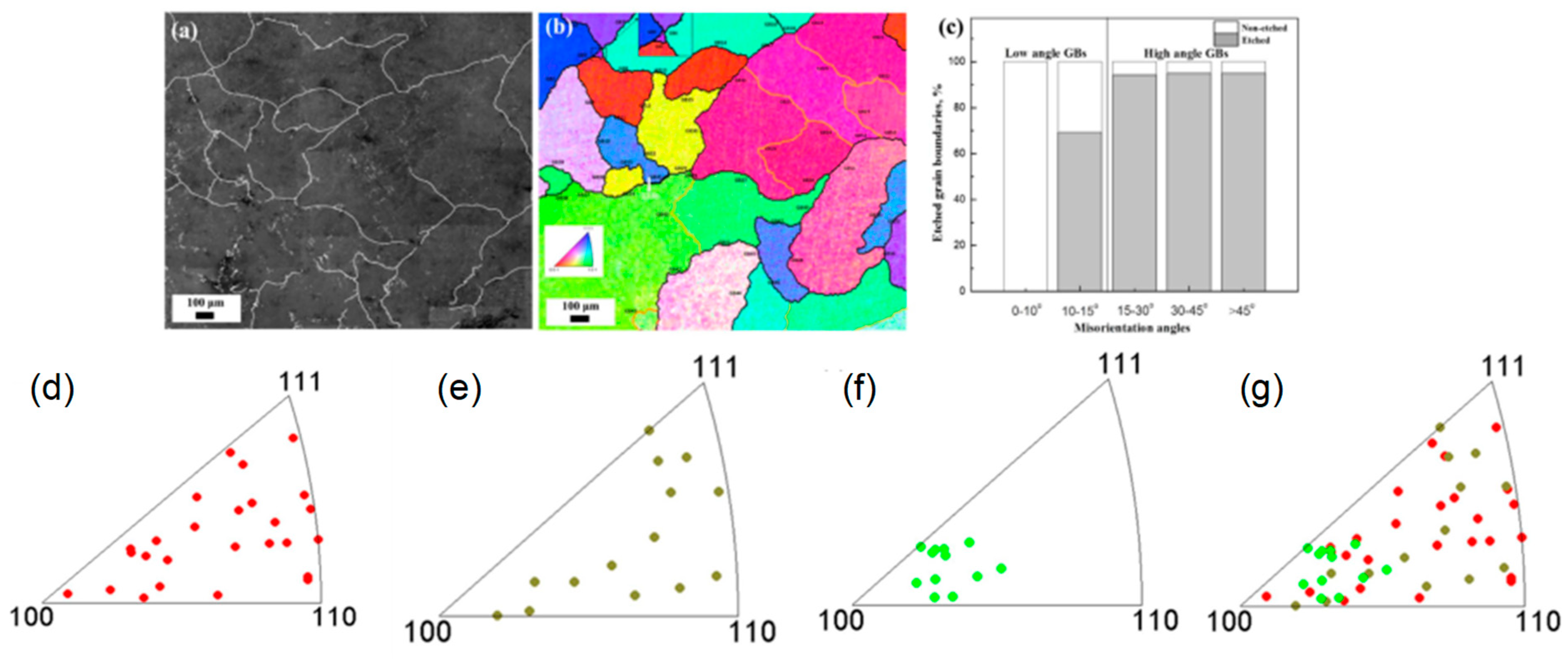
To study the effect of GB parameters on sensitization and corrosion, the Al-Mg alloy is etched with 10 % H3PO4, and the SEM micrograph is shown in Figure 6 (a & b) [147]. The GBs are numbered from GB1 to GB56 as shown in Figure 6 (b), high angle (>15°) are marked by a black, low angle (≤ 15°) yellow lines denote boundaries, and a rectangular mark is given to ∑13b GB. To further categories the 56 GB surface on the etching behavior we divide them into three major groups namely: (a) fully etched boundaries for continuous attack (2) partly etched surface nomenclature for discontinuous attack and (3) no etch boundaries for no attack. The length % of attack/non-attack for different misorientation angle is shown in Figure 6 (c). When the misorientation angle is < 10° all the GBs shows very good immunity toward attack. With the misorientation angle > 15°, the % etched length far exceeds 95%. GBs with a misorientation angle between 10-15° occupy 70% etched length. It is now evident that the how high the misorientation angle plays in precipitation and etching behavior of alloys. It is also quite clear that more precipitates forms in high angle GBs as compared to low angle GBs [143]. Al3Mg2 precipitates formed at the high angle GBs are anodic to Al matrix [129] and hence high angle GBs are severely attached.
The impact of GBs misorientation can be explained with the assistance of Gibb’s free energy, and the change in the Gibbs free energy (∆G) can be expressed as follows:
G = G s + G c + G ϕ
where ∆Gsis the surface free energy term, ∆Gc strain energy term, and Gϕ is the chemical-free energy term.
Thermodynamically, a system with lower energy respond slow to activation energy and are stable. Similarly, low angle GBs are low energy areas and are slow to activate for atomic diffusion during the formation of the precipitate and as a result, low angle GBs favors less to the formation of precipitates along their boundaries. An exception to this rule does exist, though most of the low angle GBs showed immune to attack and high angle are prone to attack. There are GBs with GB9 and GB17 with misorientation angle > 15° are less attacked and some with misorientation angle ≤ 15° are severely attacked such as GB24 and GB43. There is a special GB with ∑13b GB (GB35); despite having a misorientation angle 27.8° it showed a high reluctance to attack. So, at this junction, we can affirm that the misorientation angle is not the only parameter, but there are undoubtedly other parameters that affect the GB precipitation, corrosion, and sensitization behaviors in alloys.

10.1. Effect of GB Plane Orientations

Literature published in this direction compels us to think that precipitation behavior may bear a relationship with the GB orientation plane [142,148]. To understand the influence of GB plane orientation, the top-surface electron backscatter diffraction (EBSD) orientation maps and the GB traces[149,150] were analyzed. The same H3PO4 etched surfaces were further considered to understand the influence of GB plane orientations on precipitation. The GBs plane distributions in standard triangles are shown in Figure 6 (d-g). The plane orientations for fully and partially etched boundaries are uniformly distributed in the standard triangles. What is exciting to note here is the plane orientations of non-etched boundaries are near to[6] orientations. So, what? What is so exciting about this orientation? To answer this question, let us move to other orientations and see what made them prone to attack. The other planes close to {100} have facilitated the nucleation and growth of the β-phase as they were the habit planes[151]. Habit planes are certain planes on which certain phenomenon such as twinning[152,153,154], dislocation loops[155] or certain transformation[156] (FCC HCP) are favored (here we do not discuss much about the Habit plane, as it falls beyond the capacity of this review). When GB orientation planes are close to the Habit plane of a particular variant, copious nucleation, and growth occur in that particular variant. From the preceding discussion, it is now obvious that planes are not the habit planes and hence, these planes are reluctant toward attack.
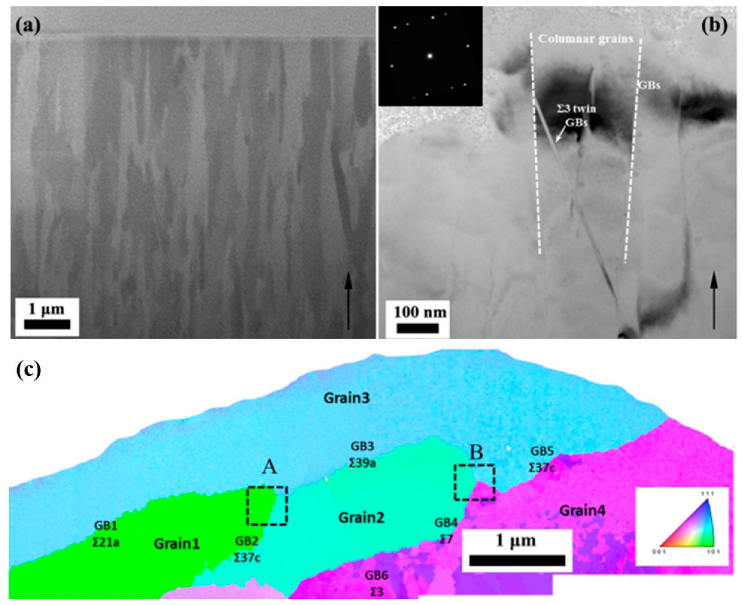
Coincidence site lattice (CSL) boundaries are special because they have a given fraction of atoms in GB plane which are nearly coincident to both the lattice which are generally separated by the GB. ∑13b showed good immunity toward attack which indicates that this special boundary does offer some special features which resist them toward acid attack and prevent corrosion. For in-depth analysis of Al-Mg alloy, the FIB and TEM cross-sectional area are considered as shown in Figure 7. The arrow in Figure 7 (a & b) indicate the {111} growth direction of the sputtered film and columnar grains are of ~ 200 nm size is clearly seen. There are few nanotwins [157] clearly visible inside the columnar grains and contain ∑3 as a special GB’s, the reflection of which is shown by selected area electron diffraction (SAED) in Figure 7 (b) inset. The columnar grains are very fine; hence, it does not serve many purposes to quantify them into a size distribution profile chart. So, a t-EBSD is shown in Figure 7 (c), the color denotes plane orientation. What is conclusive from Figure 7 (c) is the variation of the thickness of precipitates across the different GBs. GB1 is a Σ21a special GB which corresponds to θ of 18.7°, GB2 is Σ37c with θ of 49.1°, and GB3 is Σ39a with θ of 31.3°. It is observed that the β-precipitation at GB1 is much thinner than that at GB2 and GB3. This is expected since GB1 has a low angle GB misorientation. Moving to GB3 and GB5 (θ of 47.9°,), precipitates at this GB are clearly seen as expected to owe to their high angle GB. Though GB4 having a misorientation angle of 39.7°, the precipitates are much thinner on account of having low Σ7 which belongs to special GB.
At this junction, a clear picture can be presented from the above discussion on the influence of GB parameters on stress corrosion and the sensitization behavior of materials. The sensitization and stress corrosion is not only influenced by the grain misorientation but also influenced by the GB plane orientation. The prediction dependent upon grain misorientation is straight forward only when the misorientation angle is less than 10° where all the GBs show excellent immunity toward attack. The situation gets unpredictable when conditions arise with GBs being severely attacked despite having low angle misorientation and in other instances when GBs are less attacked though having a misorientation angle even > 15°. There is also no set pattern when considering GB plane orientation for predicting the corrosion behavior of the materials. Anomalous behavior does exist in this case too, for instance: precipitation is thinner in the GBs with low angle misorientation and also in GBs with high angle misorientation, there are certain exceptions of having thinner precipitates zone even tough having larger misorientation angle. In certain other cases, it is also found that few peculiar planes, often known as habit planes are the most favorable plane for nucleation and growth of precipitates favoring their formation on their planes. The situation is more complicated than expected if only misorientation angles or GB plane orientation is taken into consideration. But prediction becomes quite simple if CSL (Σ) taken into consideration for the prediction of precipitates, sensitization and corrosion activity in materials.

11. The Emergence of New Material as a Guard against Corrosion

Mg alloys are often employed in aerospace and automotive industries owing to its less weight imbibed with high strength[158,159,160]. The low oxidation resistance restricts its applicability to other domains [161]. The Mg alloys are often prone to surface degradation at elevated temperatures during metal forming, welding, and heat treatments[162]. The low oxidation resistance of Mg alloy is ascribed to its low Pilling-Bedworth (PB) ratio of 0.81 and in compactness of MgO layer[163,164]. Like another oxide layer, MgO does provide some initial protection over certain incubation periods but the migration of Mg from the lattice to search oxygen increases internal stresses, internal cracking, and de-bonding. This surge of migration causes ignition and rapid oxidation to Mg alloys[165]. Alloying with Be has shown to escalate the oxidation resistance of the Mg and Al alloys. It is believed that alloying with Be in Mg alloys lowers the inclusion impurities in Mg melt and favors the formation of more stable BeO. Be is one of the elements which has a higher affinity towards oxygen than Mg and this affinity toward oxygen is a prime factor in lowering down the oxidation rate, increase in ignition temperature and corrosion resistance of the alloys[166]. Zhao et al.[167] in his work reported that alloying with Be improves the ignition temperature to 1033 K. Several reports also published directly toward an increase in incubation temperature of Mg alloying in ppm addition of Be[168,169,170]. The mechanism by which Be improves the oxidation resistance is still unclear, but the greater emphasis has been given to the formation of more stable BeO for the increased oxidation resistance of Be-doped alloys. The following reactions of Be with Mg alloys are understood in the light of Gibbs free energy change ∆G0.
Be(l) + MgO(s) →BeO(s) + Mg(l)
The change in Gibbs free energy is given by:
G = G 0   + R T   l n α B e O α M g α M g o α B e = G 0   + R T   l n α M g α B e
(ΔG: change in free energy, α: activity factor, R and T are universal gas and temperature in Kelvin respectively).
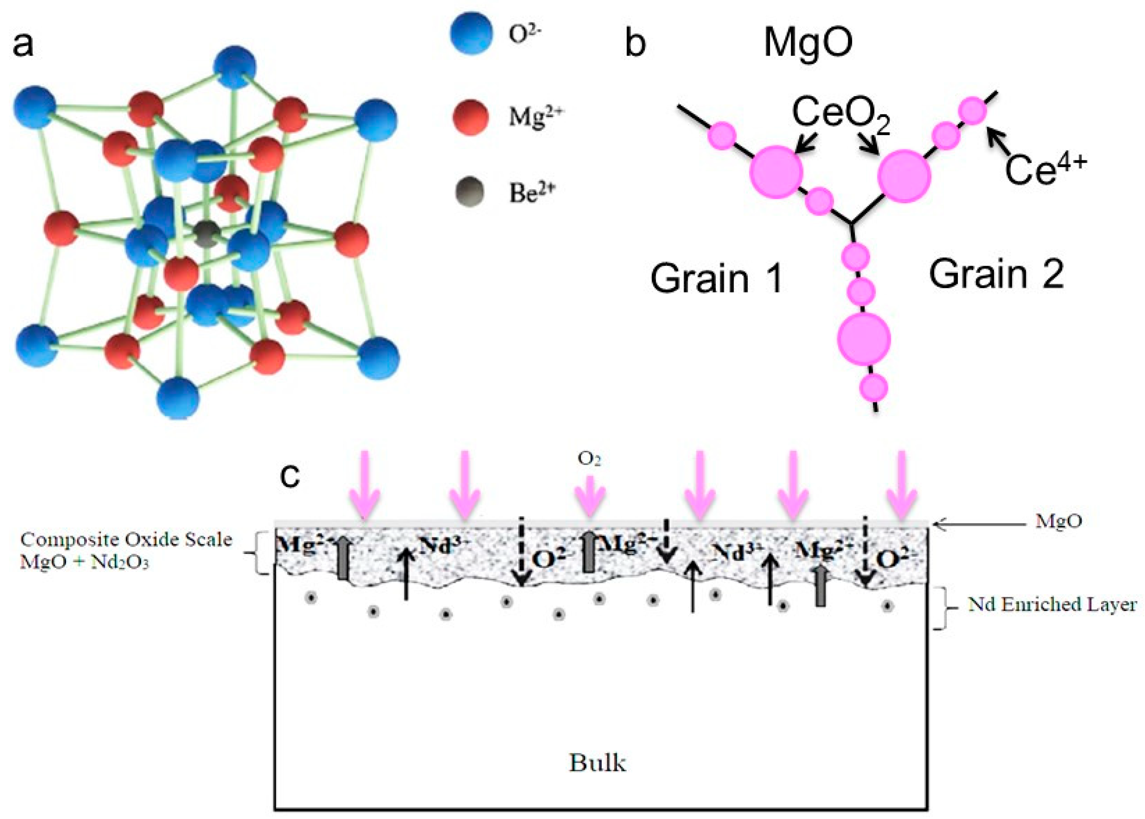
Applying the above free energy equation Zeng and co-workers[170] arrived at an interesting conclusion and presented that the formation of BeO in the presence of MgO is only possible when the Be concentration exceeds 0.88 wt% at 923 K. This conclusion well agrees with the findings of Inoue et al.[171] who calculated the PB ratio of CaO/Mg-10atm.%10Al-5atm.%Ca and BeO on AZ91 to be 1.17 and 0.62, respectively. Though the BeO layer is formed, it is incompetent to provide a protective layer to Mg substrate from oxidation due to its low PB ratio. The segregation of Be2+ ions along with MgO on and along the GBs inhibits the migration of Mg2+ ions through the GBs and look for reactive oxygen species and results in lowering the oxidation rate. The partly substituted Mg2+ by Be2+(shown in Figure 8 (a) has many added advantages as (1) partial substitution of Mg2+ by Be2+cause lattice distortion of FCC bearing Mg alloys and cause increase in solid-solution hardening and impedes dislocation motions and prevents grain boundary sliding at high temperatures, (2) the higher hardness values significantly plays a major role in reducing grain boundary cracking during stress-induced corrosion. In recent decades, Ce and Nd have commonly being used to provide better oxidation resistance to Mg alloys. A schematic representation of Ce and Nd alloying with Mg alloys has been shown in Figure 8 (b & c), respectively.
The idea is exactly similar in the case of Ce and Nd too. The formation of their respective oxides offers a passive protective film on the metal surface, and also, its segregation along with MgO on and near the GBs inhibits the upwards diffusion of cations to look for reactive oxygen. This inhibition of migration toward capturing the reactive oxygen is termed as a corrosion control mechanism. The corrosion control via the addition of Al either during the alloy design or coating a layer of aluminum oxide is primitive and is well supported through literature as well, but corrosion protection via yttrium is recently reported [173,174]. In a study on the influence of rare earth metal yttria on Mg-Y alloys, it was found that adding a certain percentage of Y in this alloy significantly boosted the corrosion behavior. The synthesized alloy denoted as Mg-mY (1 ≤ m ≤ 5) heated in an environment of SF6 at 793 K for 16 hours. The corrosion resistance of this alloy immersed in 3.5 wt.% NaCl solutions showed no sign of appreciable degradation in the structure due to the absence of scattered Mg24Y5 structure. This second phase is detrimental when it disperses evenly inside the crystal lattice structure, which causes an impurity inside the crystal. This impurity inside the crystal is detrimental to corrosion resistance. The electrochemical impedance spectra measurement indicated that the corrosion resistance of alloy increased to 6945 Ω cm-2 with a corresponding current 4.01 µA cm-2 even at a time duration of 16 hours with m = 5. When immersion time in NaCl solution was further increased the corrosion resistance value started to decline with 5223 and 4731 Ω cm-2, with a corresponding increase in current with a value of 4.99 and 5.5 µA cm-2, respectively. The reason for the decline in the corrosion resistance value is attributed to the dispersion of Mg24Y5 structure in the crystal, which acts as an impurity. Recently, a single crystal of Ni-based superalloy coated with a Si-doped Pt-modified aluminide (denoted as PtSiAl) showed an excellent oxidation/corrosion resistance even at a temperature of 1373 K for 320 hours[175]. The mass gian in the case of PtAl and PtSiAl coatings for the first 30 hours shows a surprising behavior with an increase in mass gain of PtSiAl over PtAl. However, as time progress, the gain in the mass of PtSiAl (1.26 mg cm-2) is much lower than the PtAl (1.37 mg cm-2) with both eventually settle down to a saturated value. This interesting behavior will be discussed a little later, but before that, a highlight is given to the diffusion pathway of the major elements. In both coating case, a thick layer of Al2O3 is formed. At high-temperature and with the prolong aging time, there is a gradual increase in Al2O3 layer, which induces growth stress with a phase transition from the γ-Al2O3 stable α-Al2O3. At a threshold value, which depends upon the alloy, when the total internal stress is too high, the layers fail to resist any further growth of oxide layer, and it begins to crack and peels off from the surface. This spallation and cracks offer a pathway for the rapid diffusion of the oxidative elements and initiate the degradation of the protective mechanism in the alloys. At this stage, if Al content is high enough to sustain the growth stress another α-Al2O3 is readily formed and the protection schemes continue else in the absence of Al, another oxide take over the protective Al2O3 layer. The formation of mixed oxides are generally porous in nature and thus are not protective in nature, which eventually, instigates the degradation of the substrate and the material loses its efficacy. Now, we return to our previous discussions on the protection benefits of Si-doped coating in relation to undoped PtAl coating. The area fraction of γ՛-Ni3Al in the outer layer of PtAl and PtSiAl is 12.9 and 11.7 %, respectively indicating that more of β-(Ni, Pt)Al has been consumed in PtAl than PtSiAl. It is not only the outward diffusion of the Al is important to form the protective layer, but the mutual diffusion of coating and substrate is vital in deciding the overall protection of the alloy at high-temperature[176]. The possibility of Ni and W diffusing outward from the substrate and Al diffusing inward creates the possibility of β-phase formation which grows in size over time and eventually, leading to the formation of M23C6 and µ-phase. These phases are detrimental to the corrosion protection of the alloys at high-temperature as it induces cracks just beneath the top layer and acts as an initiation site for crack propagation thus weakening the mechanical properties and corrosion resistance. Turning toward the beneficial roles of Si is acknowledged by the percentage of available Si content in the outer (0.7 at.%) and the inner layer (2-4 at. %). The lower at % of Si in the outer layer indicates the dissolution of Si and thus retarding the formation of PtAl2 and voids. Si addition in the alloy promotes the upwards migration of Ni, but the vacancies created are duly filled by Si which benefits the alloy in promoting the formation of silicides due to the affinity of Si with refractory elements especially the Cr[177]. The formation of silicides impedes the migration of refractory elements on the surface and thus impeding the detrimental phase formation on the surface thus assisting the corrosion protection of the alloys at high-temperature.

12. Present Challenges

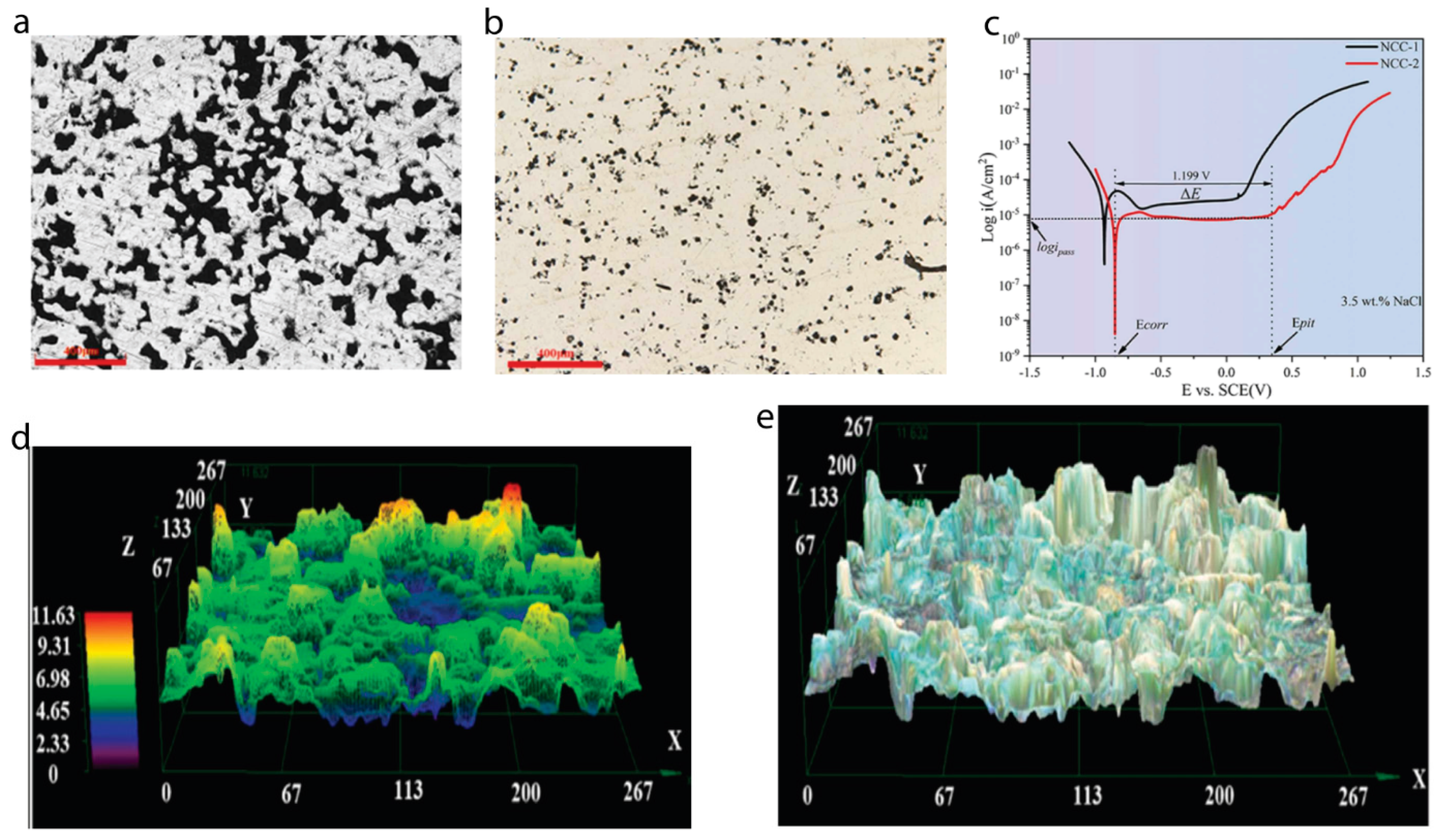
Having discussed various aspects of challenges in high-temperature alloy design and their protective measures, we come to the standpoint to look and re-explore the available long-standing challenges in corrosion science. Recently, Mortazavi and co-workers explained the formation of a messy nanostructure which helps to offer a protective layer on the high-temperature oxide-dispersion-strengthened alloy [178]. Despite several advancements in the alloy design, corrosion protection has been an open ground yet to cover successfully. In a recent study it was found that corrosion resistance in high-temperature alloy particularly Ni-based alloy could be significantly improved by addition of 5wt% rhenium (Re) [179]. In a 3.5 wr% NaCl solution, the corrosion studies exhibited that Re can significantly form a passivation layer which significantly reduces the current density, promotes higher impedance arc, and enhances corrosion resistance. The corrosion morphologies of bare Ni-based and Re-doped after polarization are revealed under optical microscope (Figure 9a-b). This image clearly reveals that a continuous pitting corrosion and several pits are interconnected revealing that this bare alloy has severely damaged by corrosion attack. While Re-doped (Figure 9b) surfaces shows somewhat identical pitting corrosion, but they are uniformly distributed and the depth of the pitting diameter are significantly reduced. Addition of Re assists in reducing the pitting corrosion kinetics thereby reflecting in enhanced corrosion resistance against oxidations at high temperature. Potential polarization studies further reveal that Re-doped alloy has a relatively lower icorr (3.847 × 10⁻⁶ A cm-2) current than bare Ni (2.005× 10⁻⁵ A cm-2) and hence a better corrosion oxidation resistance (Figure 9c). This also implies that Re-doped brings a better corrosion protective passivation films on the alloy surface. To further reveal the depth of corrosion penetration, surfaces were examined under super depth optical microscope (Figure 9d-e). It could be seen that maximum variation in the surface of re-doped in very small (~11 μm) against 37.92μm in undoped Ni. Such a small variation in surface indicates a better corrosion inhibition ability of Re-doping. These better corrosion resistances of this alloy are attributed to Re-doping. The presence of a uniform distribution of Re in the alloy results in the formation of a surface layer enriched with Nb elements. This enrichment hinders the diffusion of Mn, leading to a more continuous and dense oxide layer. As a consequence, the high-temperature oxidation resistance of the alloy is significantly improved.
Though, several novel elements have been used for corrosion inhibition in high temperature alloys, they have a limitation particularly in time duration fighting against corrosion. Technically, lack of long-term data is serious challenge in designing high-temperature alloys against corrosion. Many of these components are designed to last for many years. However, it is difficult to obtain long-term data on the corrosion behavior of materials, as this requires long-term exposure to high temperatures and corrosive environments. This lack of data makes it difficult to assess the long-term reliability of materials in high temperature corrosion applications. On the other hand, the complex behaviour of corrosion mechanism. It is highly difficult to predict the nature of corrosion under real world environment and moreover several of these mechanism can further interact among each other making corrosion studies further complex particularly at high temperature. Coating is another domain where less ground has been covered and more in-depth studies are awaited to bring novel insights on corrosion in high temperature alloys. Thus materials for extreme environmental[180] conditions needs to be further studies thoroughly to develop better alloys for tomorrow’s application to realize sustainable society.

13. Market Potentials of Protective Systems Used in High-Temperature Materials

The corrosion phenomenon occurring during the high-temperature operations is more severe than the corrosion occurring in day to day life where graphene and many other protective coatings can easily assist in building a protective layer whereas, it has little or no significant role to play in high-temperature corrosion resistance. Often, the corrosion at high-temperature is much aggravated by the presence of high-temperature, moisture, oxygen, and many oxidizing elements that make the corrosion phenomenon very complex and thus protection system succumbs to these conditions. Even very effective graphene finds itself helpless in high-temperature corrosion protection due to its inherent defects. Thus, corrosion protection at high- temperatures impose a significant challenge to the material scientist and invites them to open ground to design materials resistant enough to high-temperature. In a report by Thompson et al.[181] in the year 2007, they figured out an estimated market of ~ USD 276 billion annually for corrosion maintenance which was equivalent to 3.1 % GDP of the USA economy. The investments in corrosion in China was approximately ~310 billion USD in 2015[182]. The Indian government invests a larger share of its GDP ~ 4.5 % in corrosion maintenance.
Corrosion is a ubiquitous issue and a serious threat to the structural integrity of the components. Serious steps have been raised by the governments from all the countries to tackle this menacing threat. This can be realized from the fact that corrosion data have now been available and is shared to all to benefit from the greater understanding that results.

14. Diverse Ideas in Research Do Wonder in Science

Chemical diversity in corrosion science has a lot to offer to material protection. With the sincere efforts of researchers, academicians, and industry partners in collaborations, the past few years have witnessed unprecedented development in the corrosion protection of materials. We have seen a sublime transition in corrosion protection techniques from the early days of the inherent addition of elements like Cr, Al, W, Mo, Co, and Si to protect precious alloys to few sophisticated techniques in the modern-day. Welcoming alloying elements to unite against corrosion protection is an old tradition, yet the most effective methods available so far. Alloying elements bring the desired properties along with the complex situations of phase separations, creep growth, and grain boundary degradation over the service time. A trade-off must be often made to quench our desire in the venture of perfect corrosion-free material.
No technology is perfect; certain drawback does exist in all, and the same is true with corrosion protection and all other materials engaged in corrosion control. Novel materials, theoretical tools, and corrosion-resistant alloys must be discovered that can provide corrosion resistance at high temperatures for a longer duration.

15. Outlook and Conclusion

In conclusion, a transparent and critical appraisal has been put forth for the efforts, different materials offer against corrosion mechanisms. The quest to find the perfect material should continue in two prospects: improvements in the alloying elements should be toward pushing the performance of the materials toward high-temperature applications. Another prospect is the development of models and systems to theoretically calculate the corrosion mechanism and offer a hybrid system, in which judicious selection of fewer materials serves not only the high-temperature performance capability but also the resistance to various corrosive environments. How well such systems are employed depends upon how accurately systems had been designed taking into consideration various corrosion causing parameters. Within the next decade, we may expect the venture of a perfect material will come to see the light of the Sun and its applications in the power plants and various high-temperature applications.

Author Contributions

Conceptualization, A.N.S.; methodology, A.N.S., S.K.S.; software, A.M., S.K.S.; validation, K.-W.N., A.M. and A.N.S.; formal analysis, A.N.S., M.I.; investigation, A.N.S., M.I.; resources, K.-W.N.; data curation, A.M., S.K.S. and M.I.; writing—original draft preparation, A.N.S., S.K.S., M.I., A.M. and K.-W.N.; writing—review and editing, A.N.S. and K.-W.N.; visualization, A.N.S.; supervision, A.N.S.; project administration, A.N.S. and K.-W.N.; funding acquisition, K.-W.N. All authors have read and agreed to the published version of the manuscript.

Funding

This work was supported by the Development Program of Core Industrial Technology, funded by the Ministry of Trade, Industry & Energy of Korea (No. 20012318) and the Technology Development Program (S3126915) funded by the Ministry of SMEs and Startups (MSS, Republic of Korea).

Institutional Review Board Statement

Not applicable.

Informed Consent Statement

Not applicable.

Data Availability Statement

No new data were created or analyzed in this study.

Acknowledgments

The authors gratefully acknowledge corresponding publishers for the kind permissions to reproduce their materials, especially figures, used in this review article. The author sincerely thanks Nivedita Singh for the artworks depicted in this review.

Conflicts of Interest

The authors declare no conflicts of interest.

References

  1. Ranganathan, S. Alloyed pleasures: multimetallic cocktails. Current science 2003, 85, 1404–1406. [Google Scholar]
  2. Ruzette, A.-V.; Leibler, L. Block copolymers in tomorrow's plastics. Nat. Mater. 2005, 4, 19. [Google Scholar] [CrossRef] [PubMed]
  3. Zhou, X.; Yu, X.-x.; Kaub, T.; Martens, R.L.; Thompson, G.B. Grain Boundary Specific Segregation in Nanocrystalline Fe (Cr). Sci. Rep. 2016, 6. [Google Scholar] [CrossRef] [PubMed]
  4. Fukuda, M.; Sato, H. System evaluation for high temperature ultra supercritical steam power plants. Nihon Kikai Gakkai Ronbunshu, B Hen/Transactions of the Japan Society of Mechanical Engineers, Part B 2006, 72, 2570–2577. [Google Scholar] [CrossRef]
  5. Ahn, Y.; Bae, S.J.; Kim, M.; Cho, S.K.; Baik, S.; Lee, J.I.; Cha, J.E. Review of supercritical CO2 power cycle technology and current status of research and development. Nucl. Eng. Technol. 2015, 47, 647–661. [Google Scholar] [CrossRef]
  6. Singh, A.N.; Moitra, A.; Bhaskar, P.; Sasikala, G.; Dasgupta, A.; Bhaduri, A.K. Study of Aging-Induced Degradation of Fracture Resistance of Alloy 617 Toward High-Temperature Applications. Metall. Mater. Trans. A 2017, 48, 3269–3278. [Google Scholar] [CrossRef]
  7. Mohan, G.; Venkataraman, M.B.; Coventry, J. Sensible energy storage options for concentrating solar power plants operating above 600 °C. Renew. Sust. Energ. Rev. 2019, 107, 319–337. [Google Scholar] [CrossRef]
  8. Walczak, M.; Pineda, F.; Fernández, Á.G.; Mata-Torres, C.; Escobar, R.A. Materials corrosion for thermal energy storage systems in concentrated solar power plants. Renew. Sust. Energ. Rev. 2018, 86, 22–44. [Google Scholar] [CrossRef]
  9. Ryan, M.P.; Williams, D.E.; Chater, R.J.; Hutton, B.M.; McPhail, D.S. Why stainless steel corrodes. Nature 2002, 415, 770–774. [Google Scholar] [CrossRef]
  10. Kahraman, N.; Gulenc, B.; Findik, F. Corrosion and mechanical-microstructural aspects of dissimilar joints of Ti–6Al–4V and Al plates. Int. J. Impact Eng. 2007, 34, 1423–1432. [Google Scholar] [CrossRef]
  11. Degerbeck, J.; Gille, I. Crevice corrosion—A new crevice former. Corros. Sci. 1979, 19, 1113–1115. [Google Scholar] [CrossRef]
  12. Mazario, E.; Venegas, R.; Herrasti, P.; Alonso, M.C.; Recio, F.J. Pitting corrosion and stress corrosion cracking study in high strength steels in alkaline media. J. Solid State Electrochem. 2016, 20, 1223–1227. [Google Scholar] [CrossRef]
  13. Zhang, X.-m.; Chen, Z.-y.; Luo, H.-f.; Teng, Z.; Zhao, Y.-l.; Ling, Z.-c. Corrosion resistances of metallic materials in environments containing chloride ions: A review. Trans. Nonferrous Met. Soc. China 2022, 32, 377–410. [Google Scholar] [CrossRef]
  14. Eliaz, N.; Shemesh, G.; Latanision, R.M. Hot corrosion in gas turbine components. Eng. Fail. Anal. 2002, 9, 31–43. [Google Scholar] [CrossRef]
  15. Zeng, L.; Shuang, S.; Guo, X.P.; Zhang, G.A. Erosion-corrosion of stainless steel at different locations of a 90° elbow. Corros. Sci. 2016, 111, 72–83. [Google Scholar] [CrossRef]
  16. Ige, O.O.; Umoru, L.E. Effects of shear stress on the erosion-corrosion behaviour of X-65 carbon steel: A combined mass-loss and profilometry study. Tribol. Int. 2016, 94, 155–164. [Google Scholar] [CrossRef]
  17. Zeng, L.; Zhang, G.A.; Guo, X.P. Erosion–corrosion at different locations of X65 carbon steel elbow. Corros. Sci. 2014, 85, 318–330. [Google Scholar] [CrossRef]
  18. Gleeson, B. Still plenty to explore. Nat. Mater. 2018, 17, 574–576. [Google Scholar] [CrossRef] [PubMed]
  19. Ryan, M. Peering below the surface. Nat. Mater. 2004, 3, 663–664. [Google Scholar] [CrossRef]
  20. Iannuzzi, M.; Barnoush, A.; Johnsen, R. Materials and corrosion trends in offshore and subsea oil and gas production. npj Materials Degradation 2017, 1, 2. [Google Scholar] [CrossRef]
  21. McMillan, P.F. New materials from high-pressure experiments. Nat Mater 2002, 1, 19–25. [Google Scholar] [CrossRef] [PubMed]
  22. Taylor, C.D.; Tossey, B.M. High temperature oxidation of corrosion resistant alloys from machine learning. npj Materials Degradation 2021, 5, 38. [Google Scholar] [CrossRef]
  23. Oparaodu, K.O.; Okpokwasili, G.C. Comparison of Percentage Weight Loss and Corrosion Rate Trends in Different Metal Coupons from two Soil Environments. International Journal of Environmental Bioremediation & Biodegradation 2014, 2, 243–249. [Google Scholar]
  24. Chigondo, M.; Chigondo, F. Recent Natural Corrosion Inhibitors for Mild Steel: An Overview. J. Chem. 2016, 2016, 7. [Google Scholar] [CrossRef]
  25. Muhammad, S. Corrosion protection with eco-friendly inhibitors. Advances in Natural Sciences: Nanoscience and Nanotechnology 2011, 2, 043001. [Google Scholar]
  26. Randle, V. Grain boundary engineering: an overview after 25 years. Mater. Sci. Technol. 2010, 26, 253–261. [Google Scholar] [CrossRef]
  27. Randle, V. The measurement of grain boundary geometry; Institute of Physics Pub.: 1993.
  28. Randle, V. The coincidence site lattice and the ‘sigma enigma’. Mater. Charact. 2001, 47, 411–416. [Google Scholar] [CrossRef]
  29. Watanabe, T. Grain boundary engineering: historical perspective and future prospects. J. Mater. Sci. 2011, 46, 4095–4115. [Google Scholar] [CrossRef]
  30. Shimada, M.; Kokawa, H.; Wang, Z.J.; Sato, Y.S.; Karibe, I. Optimization of grain boundary character distribution for intergranular corrosion resistant 304 stainless steel by twin-induced grain boundary engineering. Acta Mater. 2002, 50, 2331–2341. [Google Scholar] [CrossRef]
  31. Lehockey, E.M.; Limoges, D.; Palumbo, G.; Sklarchuk, J.; Tomantschger, K.; Vincze, A. On improving the corrosion and growth resistance of positive Pb-acid battery grids by grain boundary engineering. J. Power Sources 1999, 78, 79–83. [Google Scholar] [CrossRef]
  32. Gabb, T.P.; Telesman, J.; Garg, A.; Lin, P.; Provenzano, V.; Heard, R.; Miller, H.M. Grain Boundary Engineering the Mechanical Properties of Allvac 718Plus™ Superalloy. Superalloy 718 and Derivatives 2010, 254–269. [Google Scholar]
  33. Moore, W.C. AQUA REGIA: PRELIMINARY PAPER. J. Am. Chem. Soc. 1911, 33, 1091–1099. [Google Scholar] [CrossRef]
  34. Karen, P. Oxidation State, A Long-Standing Issue. Angewandte Chemie (International Ed. in English) 2015, 54, 4716–4726. [Google Scholar] [CrossRef] [PubMed]
  35. Roduner, E. Size matters: why nanomaterials are different. Chem. Soc. Rev. 2006, 35, 583–592. [Google Scholar] [CrossRef] [PubMed]
  36. Stansbury, E.E.; Buchanan, R.A. Fundamentals of electrochemical corrosion; ASM international: 2000.
  37. Cao, G. Nanostructures and Nanomaterials:Synthesis, Properties and Applications; Imperial College Press: 2004.
  38. Jinich, A.; Rappoport, D.; Dunn, I.; Sanchez-Lengeling, B.; Olivares-Amaya, R.; Noor, E.; Even, A.B.; Aspuru-Guzik, A. Quantum Chemical Approach to Estimating the Thermodynamics of Metabolic Reactions. 2014, 4, 7022. [CrossRef]
  39. Tolpygo, V.K.; Clarke, D.R. Spalling failure of α-alumina films grown by oxidation: I. Dependence on cooling rate and metal thickness. Mater. Sci. Eng., A 2000, 278, 142–150. [Google Scholar] [CrossRef]
  40. Chen, L.; Yueming, L. Interface stress evolution considering the combined creep–plastic behavior in thermal barrier coatings. Mater. Design 2016, 89, 245–254. [Google Scholar] [CrossRef]
  41. Knipe, K.; Manero Ii, A.; Siddiqui, S.F.; Meid, C.; Wischek, J.; Okasinski, J.; Almer, J.; Karlsson, A.M.; Bartsch, M.; Raghavan, S. Strain response of thermal barrier coatings captured under extreme engine environments through synchrotron X-ray diffraction. 2014, 5, 4559. [CrossRef]
  42. Clarke, D.R.; Phillpot, S.R. Thermal barrier coating materials. Mater. Today 2005, 8, 22–29. [Google Scholar] [CrossRef]
  43. Kamrunnahar, M.; Bao, J.; Macdonald, D.D. Challenges in the theory of electron transfer at passive interfaces. Corros. Sci. 2005, 47, 3111–3139. [Google Scholar] [CrossRef]
  44. Gurney, R. The quantum mechanics of electrolysis. Proc. R. Soc. Lond. A 1931, 134, 137–154. [Google Scholar]
  45. Burstein, G.T. A hundred years of Tafel’s Equation: 1905–2005. Corros. Sci. 2005, 47, 2858–2870. [Google Scholar] [CrossRef]
  46. Liu, R.L.; Hurley, M.F.; Kvryan, A.; Williams, G.; Scully, J.R.; Birbilis, N. Controlling the corrosion and cathodic activation of magnesium via microalloying additions of Ge. Sci. Rep. 2016, 6, 28747. [Google Scholar] [CrossRef] [PubMed]
  47. Bai, P.; Bazant, M.Z. Charge transfer kinetics at the solid–solid interface in porous electrodes. Nat. Commun. 2014, 5, 3585. [Google Scholar] [CrossRef] [PubMed]
  48. Tafel, J. Über die Polarisation bei kathodischer Wasserstoffentwicklung. Z. Phys. Chem. 1905, 50, 641–712. [Google Scholar] [CrossRef]
  49. Gabe, D. The centenary of Tafel's equation. Transactions of the IMF 2005, 83, 121–124. [Google Scholar] [CrossRef]
  50. Marcus, R.A.; Sutin, N. Electron transfers in chemistry and biology. Biochimica et Biophysica Acta (BBA) - Reviews on Bioenergetics 1985, 811, 265–322. [Google Scholar] [CrossRef]
  51. Marcus, R. RA Marcus, J. Chem. Phys. 24, 966 (1956). J. Chem. Phys. 1956, 24, 966. [Google Scholar] [CrossRef]
  52. Marcus, R. On the theory of chemiluminescent electron-transfer reactions. J. Chem. Phys. 1965, 43, 2654–2657. [Google Scholar] [CrossRef]
  53. Marcus, R.A. Chemical and electrochemical electron-transfer theory. Annu. Rev. Phys. Chem. 1964, 15, 155–196. [Google Scholar] [CrossRef]
  54. Kuznetsov, A.; Ulstrup, J. Theory of electron transfer at electrified interfaces. Electrochim. Acta 2000, 45, 2339–2361. [Google Scholar] [CrossRef]
  55. Schmickler, W. A general model for electron-transfer reactions via electronic intermediate states. J. Electroanal. Chem. Interfacial Electrochem. 1982, 137, 189–198. [Google Scholar] [CrossRef]
  56. Esaki, L. Discovery of the tunnel diode. IEEE Trans. Electron Devices 1976, 23, 644–647. [Google Scholar] [CrossRef]
  57. Mizuta, H.; Tanoue, T. The physics and applications of resonant tunnelling diodes; Cambridge University Press: 2006; Volume 2.
  58. Schmickler, W.; Ulstrup, J. A theory of electron transfer reactions at film-covered metal electrodes. Chem. Phys. 1977, 19, 217–232. [Google Scholar] [CrossRef]
  59. Oksa, M.; Metsäjoki, J.; Kärki, J. Thermal Spray Coatings for High-Temperature Corrosion Protection in Biomass Co-Fired Boilers. J. Therm. Spray Technol. 2015, 24, 194–205. [Google Scholar] [CrossRef]
  60. Kang, Y.; Leng, X.; Zhao, L.; Bai, B.; Wang, X.; Chen, H. Review on the Corrosion Behaviour of Nickel-Based Alloys in Supercritical Carbon Dioxide under High Temperature and Pressure. Crystals 2023, 13, 725. [Google Scholar] [CrossRef]
  61. Cho, F.-Y.; Tung, S.-W.; Ouyang, F.-Y. High temperature oxidation behavior of high entropy alloy Al4Co3Cr25Cu10Fe25Ni33 in oxygen-containing atmospheres. Mater. Chem. Phys. 2022, 278, 125678. [Google Scholar] [CrossRef]
  62. Zhang, X.; Corrêa da Silva, C.; Liu, C.; Prabhakar, M.; Rohwerder, M. Selective oxidation of ternary Fe-Mn-Si alloys during annealing process. Corros. Sci. 2020, 174, 108859. [Google Scholar] [CrossRef]
  63. Li, L.; Guo, X. Microstructure and oxidation resistance of Ti modified Si-Mo coating on Nb-Si based ultrahigh temperature alloy. Corros. Sci. 2023, 220, 111293. [Google Scholar] [CrossRef]
  64. Reddy, G.M.S.; Prasad, C.D.; Shetty, G.; Ramesh, M.R.; Rao, T.N.; Patil, P. High-temperature oxidation behavior of plasma-sprayed NiCrAlY/TiO2 and NiCrAlY/Cr2O3/YSZ coatings on titanium alloy. Welding in the World 2022, 66, 1069–1079. [Google Scholar] [CrossRef]
  65. Nair, R.B.; Arora, H.S.; Mukherjee, S.; Singh, S.; Singh, H.; Grewal, H.S. Exceptionally high cavitation erosion and corrosion resistance of a high entropy alloy. Ultrason. Sonochem. 2018, 41, 252–260. [Google Scholar] [CrossRef]
  66. Qiu, Y.; Thomas, S.; Gibson, M.A.; Fraser, H.L.; Birbilis, N. Corrosion of high entropy alloys. npj Materials Degradation 2017, 1, 15. [Google Scholar] [CrossRef]
  67. Singh, A.N.; Islam, M.; Meena, A.; Faizan, M.; Han, D.; Bathula, C.; Hajibabaei, A.; Anand, R.; Nam, K.-W. Unleashing the Potential of Sodium-Ion Batteries: Current State and Future Directions for Sustainable Energy Storage. Adv. Funct. Mater. 2023, 33, 2304617. [Google Scholar] [CrossRef]
  68. Xie, X.; Li, N.; Liu, W.; Huang, S.; He, X.; Yu, Q.; Xiong, H.; Wang, E.; Hou, X. Research Progress of Refractory High Entropy Alloys: A Review. Chinese Journal of Mechanical Engineering 2022, 35, 142. [Google Scholar] [CrossRef]
  69. George, E.P.; Raabe, D.; Ritchie, R.O. High-entropy alloys. Nat. Rev. Mater. 2019, 4, 515–534. [Google Scholar] [CrossRef]
  70. Nascimento, C.B.; Donatus, U.; Ríos, C.T.; Oliveira, M.C.L.d.; Antunes, R.A. A review on corrosion of high entropy alloys: exploring the interplay between corrosion properties, alloy composition, passive film stability and materials selection. Materials Research 2022, 25, e20210442. [Google Scholar] [CrossRef]
  71. Godlewska, E.M.; Mitoraj-Królikowska, M.; Czerski, J.; Jawańska, M.; Gein, S.; Hecht, U. Corrosion of Al (Co) CrFeNi high-entropy alloys. Frontiers in Materials 2020, 7, 566336. [Google Scholar] [CrossRef]
  72. Liu, R.; Sun, H.; Jiang, X.; Liu, X.; Yan, W. Study of microstructure and corrosion resistance of FeCrAl-Gd alloys. Mater. Chem. Phys. 2023, 297, 127384. [Google Scholar] [CrossRef]
  73. Rodriguez, A.A.; Tylczak, J.H.; Gao, M.C.; Jablonski, P.D.; Detrois, M.; Ziomek-Moroz, M.; Hawk, J.A. Effect of Molybdenum on the Corrosion Behavior of High-Entropy Alloys CoCrFeNi2 and CoCrFeNi2Mo0. 25 under Sodium Chloride Aqueous Conditions. Advances in Materials Science and Engineering 2018, 2018. [Google Scholar] [CrossRef]
  74. Wu, H.; Zhang, S.; Wang, Z.Y.; Zhang, C.H.; Chen, H.T.; Chen, J. New studies on wear and corrosion behavior of laser cladding FeNiCoCrMox high entropy alloy coating: The role of Mo. Int. J. Refract. Met. Hard Mater. 2022, 102, 105721. [Google Scholar] [CrossRef]
  75. Mishra, A.; Shoesmith, D. The activation/depassivation of nickel–chromium–molybdenum alloys: An oxyanion or a pH effect—Part II. Electrochim. Acta 2013, 102, 328–335. [Google Scholar] [CrossRef]
  76. Hayes, J.; Gray, J.; Szmodis, A.; Orme, C. Influence of chromium and molybdenum on the corrosion of nickel-based alloys. Corrosion 2006, 62, 491–500. [Google Scholar] [CrossRef]
  77. Li, X.; Li, H.; Li, Q.; Jin, C.; Hua, K.; Wang, H. The determining role of Al addition on tribology properties and oxidation behavior at elevated temperatures of TiZrHfNb refractory high-entropy alloy. Mater. Charact. 2022, 189, 111921. [Google Scholar] [CrossRef]
  78. Lin, C.-M.; Juan, C.-C.; Chang, C.-H.; Tsai, C.-W.; Yeh, J.-W. Effect of Al addition on mechanical properties and microstructure of refractory AlxHfNbTaTiZr alloys. J. Alloys Compd. 2015, 624, 100–107. [Google Scholar] [CrossRef]
  79. Hong, M.-S.; Park, I.-J.; Kim, J.-G. Alloying effect of copper concentration on the localized corrosion of aluminum alloy for heat exchanger tube. Met. Mater. Int. 2017, 23, 708–714. [Google Scholar] [CrossRef]
  80. Seyeux, A.; Frankel, G.; Missert, N.; Unocic, K.; Klein, L.; Galtayries, A.; Marcus, P. ToF-SIMS imaging study of the early stages of corrosion in Al-Cu thin films. J. Electrochem. Soc. 2011, 158, C165–C171. [Google Scholar] [CrossRef]
  81. Larsen, M.H.; Walmsley, J.C.; Lunder, O.; Mathiesen, R.H.; Nisancioglu, K. Intergranular Corrosion of Copper-Containing AA6x xx AlMgSi Aluminum Alloys. J. Electrochem. Soc. 2008, 155, C550–C556. [Google Scholar] [CrossRef]
  82. Yan, H.Y.; Vorontsov, V.A.; Dye, D. Effect of alloying on the oxidation behaviour of Co–Al–W superalloys. Corros. Sci. 2014, 83, 382–395. [Google Scholar] [CrossRef]
  83. Giovanardi, C.; Hammer, L.; Heinz, K. Ultrathin cobalt oxide films on Ir (100)−(1× 1). Phys. Rev. B 2006, 74, 125429. [Google Scholar] [CrossRef]
  84. Chen, J.; Wu, X.; Selloni, A. Electronic structure and bonding properties of cobalt oxide in the spinel structure. Phys. Rev. B 2011, 83, 245204. [Google Scholar] [CrossRef]
  85. Tan, H.B.; Ke, K.; Ma, B.G.; Xiao, J. Effect and Solid Solution Mechanism of Co2O3 during C3S Formation. In Proceedings of the Advanced Materials Research; 2011; pp. 1587–1592. [Google Scholar]
  86. Dwivedi, D.; Lepková, K.; Becker, T. Carbon steel corrosion: a review of key surface properties and characterization methods. RSC Adv. 2017, 7, 4580–4610. [Google Scholar] [CrossRef]
  87. Kangazian, J.; Shamanian, M. Micro-texture and corrosion behavior of dissimilar joints of UNS S32750 stainless steel/UNS N08825 Ni-based superalloy. Mater. Charact. 2019, 155, 109802. [Google Scholar] [CrossRef]
  88. Bateni, M.R.; Szpunar, J.A.; Wang, X.; Li, D.Y. The effect of wear and corrosion on internal crystalline texture of carbon steel and stainless steel. Wear 2005, 259, 400–404. [Google Scholar] [CrossRef]
  89. Fushimi, K.; Miyamoto, K.; Konno, H. Anisotropic corrosion of iron in pH 1 sulphuric acid. Electrochim. Acta 2010, 55, 7322–7327. [Google Scholar] [CrossRef]
  90. Kumar, B.R.; Singh, R.; Mahato, B.; De, P.; Bandyopadhyay, N.; Bhattacharya, D. Effect of texture on corrosion behavior of AISI 304L stainless steel. Mater. Charact. 2005, 54, 141–147. [Google Scholar] [CrossRef]
  91. Park, S.-A.; Kim, J.; He, Y.; Shin, K.; Yoon, J. Comparative study on the corrosion behavior of the cold rolled and hot rolled low-alloy steels containing copper and antimony in flue gas desulfurization environment. The Physics of Metals and Metallography 2014, 115, 1285–1294. [Google Scholar] [CrossRef]
  92. Chen, Y.; Deng, W.; Zhu, S.; Chen, G.; Wang, L.; Su, Y. Preparation of super-hydrophobic surface with micro-nano layered structure on 316 stainless steel by one-step wet chemical method. Colloids and Surfaces A: Physicochemical and Engineering Aspects 2022, 655, 130291. [Google Scholar] [CrossRef]
  93. Wang, L.; Xiao, X.; Liu, E.; Yu, S.; Yin, X.; Wang, J.; Zhu, G.; Li, Q.; Li, J. Fabrication of superhydrophobic needle-like Ca-P coating with anti-fouling and anti-corrosion properties on AZ31 magnesium alloy. Colloids and Surfaces A: Physicochemical and Engineering Aspects 2021, 620, 126568. [Google Scholar] [CrossRef]
  94. Zhang, Z.; Zhao, J.; Lei, Y.; Wang, Y.; Zhou, G.; Xu, C.; Rao, Y.; Wang, K. Preparation of intricate nanostructures on 304 stainless steel surface by SiO2-assisted HF etching for high superhydrophobicity. Colloids and Surfaces A: Physicochemical and Engineering Aspects 2020, 586, 124287. [Google Scholar] [CrossRef]
  95. Xu, W.; Song, J.; Sun, J.; Lu, Y.; Yu, Z. Rapid fabrication of large-area, corrosion-resistant superhydrophobic Mg alloy surfaces. ACS Appl. Mater. Inter. 2011, 3, 4404–4414. [Google Scholar] [CrossRef] [PubMed]
  96. Liu, Y.X.; Lei, X.W.; Hao, L.Y.; Han, S.X.; Yang, R.N.; Wang, N. The anisotropy electrochemical corrosion behavior of Ni-based single crystal superalloy on different crystal planes: An investigation from the film growth aspect. Applied Surface Science 2022, 576, 151785. [Google Scholar] [CrossRef]
  97. Zhang, L.; Ojo, O. Crystallographic orientation dependence of corrosion behavior of a single crystal nickel-based alloy. Metall. Mater. Trans. A 2018, 49, 295–304. [Google Scholar] [CrossRef]
  98. Yu, J.; Glazoff, M.V.; Capolungo, L.; Gao, M.C.; Ilevbare, G.O. Boron substitution induced FCC Fe/Cr23C6 interfacial strengthening: An ab initio study. Computational Materials Science 2023, 228, 112370. [Google Scholar] [CrossRef]
  99. Marcus, P.; Maurice, V. Atomic level characterization in corrosion studies. Philosophical Transactions of the Royal Society A: Mathematical, Physical and Engineering Sciences 2017, 375, 20160414. [Google Scholar] [CrossRef] [PubMed]
  100. Kokalj, A. Molecular modeling of organic corrosion inhibitors: Calculations, pitfalls, and conceptualization of molecule–surface bonding. Corros. Sci. 2021, 193, 109650. [Google Scholar] [CrossRef]
  101. Mendonça, G.L.F.; Costa, S.N.; Freire, V.N.; Casciano, P.N.S.; Correia, A.N.; Lima-Neto, P.d. Understanding the corrosion inhibition of carbon steel and copper in sulphuric acid medium by amino acids using electrochemical techniques allied to molecular modelling methods. Corros. Sci. 2017, 115, 41–55. [Google Scholar] [CrossRef]
  102. Zuili, D.; Maurice, V.; Marcus, P. Surface structure of nickel in acid solution studied by in situ scanning tunneling microscopy. J. Electrochem. Soc. 2000, 147, 1393–1400. [Google Scholar] [CrossRef]
  103. Magnussen, O.M.; Scherer, J.; Ocko, B.M.; Behm, R.J. In Situ X-ray Scattering Study of the Passive Film on Ni(111) in Sulfuric Acid Solution. The Journal of Physical Chemistry B 2000, 104, 1222–1226. [Google Scholar] [CrossRef]
  104. Scherer, J.; Ocko, B.; Magnussen, O. Structure, dissolution, and passivation of Ni (111) electrodes in sulfuric acid solution: an in situ STM, X-ray scattering, and electrochemical study. Electrochim. Acta 2003, 48, 1169–1191. [Google Scholar] [CrossRef]
  105. Maurice, V.; Talah, H.; Marcus, P. A scanning tunneling microscopy study of the structure of thin oxide films grown on Ni (111) single crystal surfaces by anodic polarization in acid electrolyte. Surf. Sci. 1994, 304, 98–108. [Google Scholar] [CrossRef]
  106. Bouzoubaa, A.; Diawara, B.; Maurice, V.; Minot, C.; Marcus, P. Ab initio study of the interaction of chlorides with defect-free hydroxylated NiO surfaces. Corros. Sci. 2009, 51, 941–948. [Google Scholar] [CrossRef]
  107. Bouzoubaa, A.; Diawara, B.; Maurice, V.; Minot, C.; Marcus, P. Ab initio modelling of localized corrosion: Study of the role of surface steps in the interaction of chlorides with passivated nickel surfaces. Corros. Sci. 2009, 51, 2174–2182. [Google Scholar] [CrossRef]
  108. Maurice, V.; Klein, L.; Marcus, P. Atomic structure of metastable pits formed on nickel. Electrochem. Solid-State Lett. 2001, 4, B1–B3. [Google Scholar] [CrossRef]
  109. Seyeux, A.; Maurice, V.; Klein, L.; Marcus, P. In situ STM study of the effect of chloride on passive film on nickel in alkaline solution. J. Electrochem. Soc. 2006, 153, B453–B463. [Google Scholar] [CrossRef]
  110. Marcus, P.; Maurice, V.; Strehblow, H.-H. Localized corrosion (pitting): A model of passivity breakdown including the role of the oxide layer nanostructure. Corros. Sci. 2008, 50, 2698–2704. [Google Scholar] [CrossRef]
  111. Maurice, V.; Nakamura, T.; Klein, L.; Marcus, P. Initial stages of localised corrosion by pitting of passivated nickel surfaces studied by STM and AFM. Local Probe Techniques for Corrosion Research, EFC Publications.
  112. Ball, P. A sense of dislocations. Nat. Mater. 2015, 14, 968–968. [Google Scholar] [CrossRef] [PubMed]
  113. Dang, S.H.; Li, C.X.; Han, P.D. Synergetic effects of impurities and alloying element Cr on oxidation and dissolution corrosion of Ni (111) surfaces: A DFT study. Chinese Journal of Physics 2019, 61, 1–7. [Google Scholar] [CrossRef]
  114. Watanabe, T.; Tsurekawa, S.; Zhao, X.; Zuo, L. The Coming of Grain Boundary Engineering in the 21st Century. In Microstructure and Texture in Steels: and Other Materials, Haldar, A., Suwas, S., Bhattacharjee, D., Eds.; Springer London: London, 2009; pp. 43–82. [Google Scholar]
  115. Watanabe, T. An approach to grain-boundary design for strong and ductile polycrystals. Res Mechanica 1984, 11, 47–84. [Google Scholar]
  116. Randle, V.; Brown, A. Development of grain misorientation texture, in terms of coincident site lattice structures, as a function of thermomechanical treatments. Philos. Mag. A 1989, 59, 1075–1089. [Google Scholar] [CrossRef]
  117. Cheng, Y.; Jin, Z.H.; Zhang, Y.W.; Gao, H. On intrinsic brittleness and ductility of intergranular fracture along symmetrical tilt grain boundaries in copper. Acta Mater. 2010, 58, 2293–2299. [Google Scholar] [CrossRef]
  118. Hossein Nedjad, S.; Nili Ahmadabadi, M.; Furuhara, T. Correlation between the intergranular brittleness and precipitation reactions during isothermal aging of an Fe–Ni–Mn maraging steel. Mater. Sci. Eng., A 2008, 490, 105–112. [Google Scholar] [CrossRef]
  119. Yan, J.; Heckman, N.M.; Velasco, L.; Hodge, A.M. Improve sensitization and corrosion resistance of an Al-Mg alloy by optimization of grain boundaries. 2016, 6, 26870. [CrossRef]
  120. Yamaura, S.-i.; Tsurekawa, S.; Watanabe, T. The Control of Oxidation-Induced Intergranular Embrittlement by Grain Boundary Engineering in Rapidly Solidified Ni-Fe Alloy Ribbons. Mater. Trans. 2003, 44, 1494–1502. [Google Scholar] [CrossRef]
  121. Kobayashi, S.; Maruyama, T.; Tsurekawa, S.; Watanabe, T. Grain boundary engineering based on fractal analysis for control of segregation-induced intergranular brittle fracture in polycrystalline nickel. Acta Mater. 2012, 60, 6200–6212. [Google Scholar] [CrossRef]
  122. Kobayashi, S.; Tsurekawa, S.; Watanabe, T. A new approach to grain boundary engineering for nanocrystalline materials. Beilstein J. Nanotechnol. 2016, 7, 1829. [Google Scholar] [CrossRef] [PubMed]
  123. Watanabe, T.; Tsurekawa, S.; Fujii, H.; Kanno, T. The control of texture and grain boundary microstructure by magnetic annealing. In Proceedings of the Mater. Sci. Forum; 2005; pp. 1151–1158. [Google Scholar]
  124. Bettayeb, M.; Maurice, V.; Klein, L.H.; Lapeire, L.; Verbeken, K.; Marcus, P. Nanoscale Intergranular Corrosion and Relation with Grain Boundary Character as Studied In Situ on Copper. J. Electrochem. Soc. 2018, 165, C835–C841. [Google Scholar] [CrossRef]
  125. Yang, F.-q.; Xue, H.; Zhao, L.-y.; Fang, X.-R.; Zhang, H.-b. Effects of Crystal Orientation and Grain Boundary Inclination on Stress Distribution in Bicrystal Interface of Austenite Stainless Steel 316L. Adv. Mater. Sci. Eng. 2019, 2019. [Google Scholar] [CrossRef]
  126. Ralston, K.; Birbilis, N. Effect of grain size on corrosion: a review. Corrosion 2010, 66, 075005–075005. [Google Scholar] [CrossRef]
  127. Polmear, I. Light alloys- Metallurgy of the light metals//((Book)). London and New York, Edward Arnold, 1989, 288.
  128. Shahabi-Navid, M.; Esmaily, M.; Svensson, J.-E.; Halvarsson, M.; Nyborg, L.; Cao, Y.; Johansson, L.-G. NaCl-induced atmospheric corrosion of the MgAl alloy AM50-the influence of CO2. J. Electrochem. Soc. 2014, 161, C277–C287. [Google Scholar] [CrossRef]
  129. Birbilis, N.; Buchheit, R. Electrochemical characteristics of intermetallic phases in aluminum alloys an experimental survey and discussion. J. Electrochem. Soc. 2005, 152, B140–B151. [Google Scholar] [CrossRef]
  130. Jones, R.; Baer, D.; Danielson, M.; Vetrano, J. Role of Mg in the stress corrosion cracking of an Al-Mg alloy. Metall. Mater. Trans. A. 2001, 32, 1699–1711. [Google Scholar] [CrossRef]
  131. Zhang, R.; Gupta, R.; Davies, C.; Hodge, A.; Tort, M.; Xia, K.; Birbilis, N. The influence of grain size and grain orientation on sensitization in AA5083. Corrosion 2015, 72, 160–168. [Google Scholar]
  132. Choi, D.-H.; Ahn, B.-W.; Quesnel, D.J.; Jung, S.-B. Behavior of β phase (Al 3 Mg 2) in AA 5083 during friction stir welding. Intermetallics 2013, 35, 120–127. [Google Scholar] [CrossRef]
  133. Walczak, M.S.; Morales-Gil, P.; Belashehr, T.; Kousar, K.; Lozada, P.A.; Lindsay, R. Determining the Chemical Composition of Corrosion Inhibitor/Metal Interfaces with XPS: Minimizing Post Immersion Oxidation. Journal of visualized experiments: JoVE.
  134. Wang, Y.; Gupta, R.; Sukiman, N.; Zhang, R.; Davies, C.; Birbilis, N. Influence of alloyed Nd content on the corrosion of an Al–5Mg alloy. Corros. Sci. 2013, 73, 181–187. [Google Scholar] [CrossRef]
  135. Zhang, Y.; Xiao, Z.; Zhao, Y.; Li, Z.; Xing, Y.; Zhou, K. Effect of thermo-mechanical treatments on corrosion behavior of Cu-15Ni-8Sn alloy in 3.5 wt% NaCl solution. Mater. Chem. Phys. 2017, 199, 54–66. [Google Scholar] [CrossRef]
  136. Tan, L.; Allen, T.R. Effect of thermomechanical treatment on the corrosion of AA5083. Corros. Sci. 2010, 52, 548–554. [Google Scholar] [CrossRef]
  137. Oguocha, I.; Adigun, O.; Yannacopoulos, S. Effect of sensitization heat treatment on properties of Al–Mg alloy AA5083-H116. J. Mater. Sci. 2008, 43, 4208–4214. [Google Scholar] [CrossRef]
  138. Shi, P.; Hu, R.; Zhang, T.; Yuan, L.; Li, J. Grain boundary character distribution and its effect on corrosion of Ni–23Cr–16Mo superalloy. Mater. Sci. Technol. 2017, 33, 84–91. [Google Scholar] [CrossRef]
  139. Watanabe, T.; Tsurekawa, S. The control of brittleness and development of desirable mechanical properties in polycrystalline systems by grain boundary engineering. Acta Mater. 1999, 47, 4171–4185. [Google Scholar] [CrossRef]
  140. Hickman, J.; Mishin, Y. Extra variable in grain boundary description. Phys. Rev. Mater. 2017, 1, 010601. [Google Scholar] [CrossRef]
  141. Yan, J.; Heckman, N.M.; Velasco, L.; Hodge, A.M. Improve sensitization and corrosion resistance of an Al-Mg alloy by optimization of grain boundaries. Sci. Rep. 2016, 6, 26870. [Google Scholar] [CrossRef] [PubMed]
  142. Homer, E.R.; Patala, S.; Priedeman, J.L. Grain boundary plane orientation fundamental zones and structure-property relationships. Sci. Rep. 2015, 5. [Google Scholar] [CrossRef]
  143. Davenport, A.J.; Yuan, Y.; Ambat, R.; Connolly, B.J.; Strangwood, M.; Afseth, A.; Scamans, G.M. Intergranular corrosion and stress corrosion cracking of sensitised AA5182. In Proceedings of the Mater. Sci. Forum; 2006; pp. 641–646. [Google Scholar]
  144. Kaigorodova, L. The effect of grain-boundary structure formation on β-precipitation in aged Al-Mg alloys. In Proceedings of the Mater. Sci. Forum; 1999; pp. 477–480. [Google Scholar]
  145. D’Antuono, D.S.; Gaies, J.; Golumbfskie, W.; Taheri, M. Grain boundary misorientation dependence of β phase precipitation in an Al–Mg alloy. Scripta Mater. 2014, 76, 81–84. [Google Scholar] [CrossRef]
  146. Brandon, D. The structure of high-angle grain boundaries. Acta Metall. 1966, 14, 1479–1484. [Google Scholar] [CrossRef]
  147. Yan, J.; Heckman, N.M.; Velasco, L.; Hodge, A.M. Improve sensitization and corrosion resistance of an Al-Mg alloy by optimization of grain boundaries. Sci. Rep. 2016, 6, 26870. [Google Scholar] [CrossRef] [PubMed]
  148. Zhao, Y.; Polyakov, M.N.; Mecklenburg, M.; Kassner, M.E.; Hodge, A.M. The role of grain boundary plane orientation in the β phase precipitation of an Al–Mg alloy. Scripta Mater. 2014, 89, 49–52. [Google Scholar] [CrossRef]
  149. Zhao, Y. The role of nanotwins and grain boundary plane in the thermal, corrosion, and sensitization behavior of nanometals; University of Southern California: 2014.
  150. Zhou, X.; Yu, X.-x.; Kaub, T.; Martens, R.L.; Thompson, G.B. Grain Boundary Specific Segregation in Nanocrystalline Fe(Cr). 2016, 6, 34642. [CrossRef]
  151. Klostermann, J. The concept of the habit plane and the phenomenological theories of the martensite transformation. J. Less Common Met. 1972, 28, 75–94. [Google Scholar] [CrossRef]
  152. Baur, A.P.; Cayron, C.; Logé, R.E. {225}(γ) habit planes in martensitic steels: from the PTMC to a continuous model. Sci. Rep. 2017, 7, 40938. [Google Scholar] [CrossRef]
  153. Rusakov, G.M.; Lobanov, M.L.; Redikultsev, A.A.; Kagan, I.V. Retention of the Twinning Σ3 Misorientation in the Process of Lattice Transformation during Cold Rolling of a Fe3 Pct Si Single Crystal. Metall. Mater. Trans. A. 2011, 42, 1435–1438. [Google Scholar] [CrossRef]
  154. Wood, R.M.; Entwisle, A.R. Martensite habit planes in Fe-Mn-C alloys. Metal Science 1976, 10, 72–76. [Google Scholar] [CrossRef]
  155. Dai, C.; Balogh, L.; Yao, Z.; Daymond, M.R. The habit plane of 〈a〉-type dislocation loops in α-zirconium: an atomistic study. Philos. Mag. 2017, 97, 944–956. [Google Scholar] [CrossRef]
  156. Cayron, C. Continuous atomic displacements and lattice distortions during martensitic transformations in fcc-bcc-hcp systems. arXiv preprint arXiv:1502.07152, arXiv:1502.07152 2015.
  157. Zhang, Y.-W. Mechanical properties: Nanotwins only. Nat Nano 2012, 7, 551–552. [Google Scholar] [CrossRef]
  158. Song, G.L.; Atrens, A. Corrosion mechanisms of magnesium alloys. Adv. Eng. Mater. 1999, 1, 11–33. [Google Scholar] [CrossRef]
  159. Jiang, B.; Liu, W.; Qiu, D.; Zhang, M.-X.; Pan, F. Grain refinement of Ca addition in a twin-roll-cast Mg–3Al–1Zn alloy. Mater. Chem. Phys. 2012, 133, 611–616. [Google Scholar] [CrossRef]
  160. Jeong, J.; Im, J.; Song, K.; Kwon, M.; Kim, S.K.; Kang, Y.-B.; Oh, S.H. Transmission electron microscopy and thermodynamic studies of CaO-added AZ31 Mg alloys. Acta Mater. 2013, 61, 3267–3277. [Google Scholar] [CrossRef]
  161. Prasad, A.; Shi, Z.; Atrens, A. Influence of Al and Y on the ignition and flammability of Mg alloys. Corros. Sci. 2012, 55, 153–163. [Google Scholar] [CrossRef]
  162. Czerwinski, F. Overcoming Barriers. Advanced Materials & Processes.
  163. Czerwinski, F. Controlling the ignition and flammability of magnesium for aerospace applications. Corros. Sci. 2014, 86, 1–16. [Google Scholar] [CrossRef]
  164. Medved, J.; Mrvar, P.; Vončina, M. Oxidation resistance of cast magnesium alloys. Oxid. Met. 2009, 71, 257–270. [Google Scholar] [CrossRef]
  165. Tan, Q.; Atrens, A.; Mo, N.; Zhang, M.-X. Oxidation of magnesium alloys at elevated temperatures in air: A review. Corros. Sci. 2016, 112, 734–759. [Google Scholar] [CrossRef]
  166. Czerwinski, F. Oxidation characteristics of magnesium alloys. JOM 2012, 64, 1477–1483. [Google Scholar] [CrossRef]
  167. Weimin, Z.; Yong, S.; Haipeng, L.; Chunyong, L. The effects of some elements on the igniting temperature of magnesium alloys. Materials Science and Engineering: B 2006, 127, 105–107. [Google Scholar] [CrossRef]
  168. Czerwinski, F. The early stage oxidation and evaporation of Mg–9% Al–1% Zn alloy. Corrosion Science 2004, 46, 377–386. [Google Scholar] [CrossRef]
  169. Tan, Q.; Mo, N.; Jiang, B.; Pan, F.; Atrens, A.; Zhang, M.-X. Oxidation resistance of Mg–9Al–1Zn alloys micro-alloyed with Be. Scripta Mater. 2016, 115, 38–41. [Google Scholar] [CrossRef]
  170. Zeng, X.; Wang, Q.; Lü, Y.; Ding, W.; Zhu, Y.; Zhai, C.; Lu, C.; Xu, X. Behavior of surface oxidation on molten Mg–9Al–0.5 Zn–0.3 Be alloy. Mater. Sci. Eng., A 2001, 301, 154–161. [Google Scholar] [CrossRef]
  171. Inoue, S.-i.; Yamasaki, M.; Kawamura, Y. Formation of an incombustible oxide film on a molten Mg-Al-Ca alloy. Corros. Sci. 2017, 122, 118–122. [Google Scholar] [CrossRef]
  172. Aydin, D.S.; Bayindir, Z.; Hoseini, M.; Pekguleryuz, M.O. The high temperature oxidation and ignition behavior of Mg–Nd alloys part I: The oxidation of dilute alloys. J. Alloys Compd. 2013, 569, 35–44. [Google Scholar] [CrossRef]
  173. Cheng, X.; Fan, L.; Liu, L.; Du, K.; Wang, D. Effect of doping aluminum and yttrium on high-temperature oxidation behavior of Ni-11Fe-10Cu alloy. J. Rare Earth 2016, 34, 1139–1147. [Google Scholar] [CrossRef]
  174. Liu, X.; Shan, D.; Song, Y.; Han, E.-h. Influence of yttrium element on the corrosion behaviors of Mg–Y binary magnesium alloy. Journal of Magnesium and Alloys 2017, 5, 26–34. [Google Scholar] [CrossRef]
  175. Fan, Q.; Yu, H.; Wang, T.; Liu, Y. Microstructure and Oxidation Resistance of a Si Doped Platinum Modified Aluminide Coating Deposited on a Single Crystal Superalloy. Coatings 2018, 8, 264. [Google Scholar] [CrossRef]
  176. Fan, Q.; Peng, X.; Yu, H.; Jiang, S.; Gong, J.; Sun, C. The isothermal and cyclic oxidation behaviour of two Co modified aluminide coatings at high temperature. Corros. Sci. 2014, 84, 42–53. [Google Scholar] [CrossRef]
  177. Azarmehr, S.A.; Shirvani, K.; Schütze, M.; Galetz, M. Microstructural evolution of silicon-platinum modified aluminide coatings on superalloy GTD-111. Surf. Coat. Technol. 2017, 321, 455–463. [Google Scholar] [CrossRef]
  178. Mortazavi, N.; Geers, C.; Esmaily, M.; Babic, V.; Sattari, M.; Lindgren, K.; Malmberg, P.; Jönsson, B.; Halvarsson, M.; Svensson, J.E.; et al. Interplay of water and reactive elements in oxidation of alumina-forming alloys. Nat. Mater. 2018, 17, 610–617. [Google Scholar] [CrossRef]
  179. Zhang, Z.; Wang, H.; Wu, J.; Wang, C.; Hou, Z.; Tang, Y.; Liu, Z.; Ouyang, X. Improvement of corrosion resistance of Ni-based alloy by adding 5 wt.% rhenium. Mater. Today Commun. 2023, 35, 106387. [Google Scholar] [CrossRef]
  180. Eswarappa Prameela, S.; Pollock, T.M.; Raabe, D.; Meyers, M.A.; Aitkaliyeva, A.; Chintersingh, K.-L.; Cordero, Z.C.; Graham-Brady, L. Materials for extreme environments. Nat. Rev. Mater. 2023, 8, 81–88. [Google Scholar] [CrossRef]
  181. Thompson, N.G.; Yunovich, M.; Dunmire, D. Cost of corrosion and corrosion maintenance strategies. Corros. Rev. 2007, 25, 247–262. [Google Scholar] [CrossRef]
  182. Hou, B.; Li, X.; Ma, X.; Du, C.; Zhang, D.; Zheng, M.; Xu, W.; Lu, D.; Ma, F. The cost of corrosion in China. npj Materials Degradation 2017, 1, 4. [Google Scholar] [CrossRef]
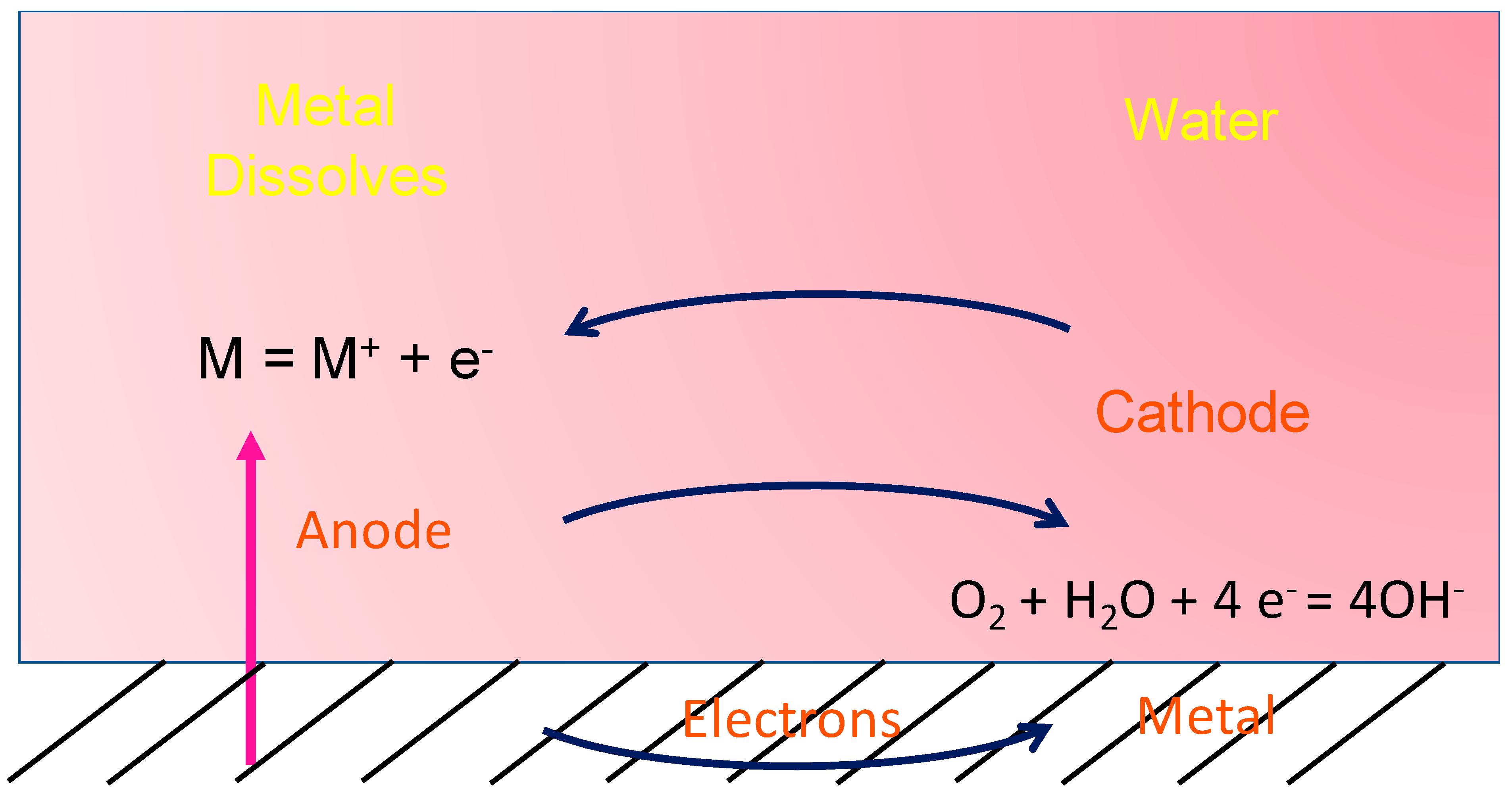
Figure 1. A schematic representation of the corrosion phenomenon occurring inside a material exposed to environments.
Preprints 111635 g001
Figure 2. The schematic representation of oxide diffusing inside and metal cation diffusion outward. When metal atoms are ionized, they move into the oxide layer, creating a vacancy at the interface.
Preprints 111635 g002
Figure 3. (a) Microhardness profile for 316L grade SS and various Mo composition in HEACs. (b) Obtained average friction coefficient. (c) Histogram plots showing the specific wear rates. Adapted from ref. [74] Copyright 2022, Elsevier. (d) the linear-fit between YS and Al concentration for Alx(TiZrHfNb)100-x. (e) Profile showing wear rate and hardness variation w.r.to Al concentration. (f) logarithm plot of mass change against time (s) for Al-5/7/12 wt%. Adapted from ref.[77] Copyright 2022, Elsevier.
Preprints 111635 g003
Figure 4. (a)Water contact angle and slip angle of SS and SHP-SS. (b) Polarization curve for SS (raw material) and SHP-SS (SS5; here 5 indicates sample number with H2O2/HF ratio in 0.2/1, reaction time (50 min), and mass ratio of PFOS/HF in 1/100). (c) SEM image of SS5. Adapted from ref. [92] Copyright 2022, Elsevier. (d) Schematic illustration of DD5 superalloy with different crystallographic planes. (e) Potentiodynamic polarization curve in 3.5 wt% NaCl solution. (f) Potentiostatic polarization curve obtained in 3.5 wt% NaCl solution for DD5 superlloy with different planes. Adapted from ref.[96] Copyright 2022, Elsevier. (g) Various chemical energies for FCC Fe/Cr23C6 interface with and without B-substitution of carbon atoms. Here A1-A4 and B1-B3 signifies the boron atom replacing carbon atom in the first, second, third, and fourth layer of Cr23C6 from A- and B-termination, respectively. (h) Side view of highly symmetrical (001) interface of FCC Fe/Cr23C6. Adapted from ref. [98] Copyright 2023, Elsevier.
Preprints 111635 g004
Figure 5. (a)Surface model for Ni (111); Red-impurities atoms; Blue- Ni; yellow-indicates Ni site substituted by Cr-atom. (b) Surface energies of Ni (111) and Ni-Cr systems. (c) Segregation energy of different impurities atoms onto Ni (111) and Ni-Cr (111) systems. Adapted from ref. [113]. Copyright 2019, Elsevier.
Preprints 111635 g005
Figure 6. (a) SEM images of the top surface, (b) corresponding EBSD grain orientation map of sensitized as-received Al-Mg alloy after H3PO4 etching. (black and yellow lines denote high-angle GBs (>15°) and low-angle GBs(=15°), respectively. The white rectangle marks the special GBs of 13b; (c) Bar graph depicts the percentage length of as-received Al-Mg alloy in non-etched/etched GBs with H3PO4 etching showing different misorientation angles; (d) standard triangles denote the GB plane orientations of sensitized as-received Al-Mg alloy for fully-etched boundaries, (e) partially-etched boundaries, (f) non-etched boundaries, (g) all boundaries. Adapted from ref. [147]. Copyright 2016, Springer Nature.
Preprints 111635 g006
Figure 7. Cross-sectional micrographs of sputtered Al-Mg alloy under FIB and TEM; (a) FIB cross-sectional image, Bright field TEM (b) showing columnar grains. The inset image shows the SAED pattern. (c) Cross-sectional image of transmitted backscatter electron diffraction sensitized sputtered Al-Mg alloy. The color of the grain corresponds to the plane orientation. Adapted from ref. [147]. Copyright 2016, Springer Nature.
Preprints 111635 g007
Figure 8. Effect of substituted Mg2+ by novel cations on corrosion behavior. (a) The lattice parameters of αMgO and αBe-MgO are 4.293 and 4.201 Å, respectively. Their lattice values indicate a distorted structure on accommodation of Be in the matrix. (b) the presences of Cecation and its oxide together lies on and along the GBs and ultimately restricts the easy flow of Mg2+ cations. Reproduced from Ref.[165] with permission from Elsevier. (c) the formation of MgO during the oxidation at high temperature increases the concentration of Nd on the surface favoring the formation of a more stable passive layer of Nd2O3. Adapted from ref. [172]. Copyright 2013, Elsevier.
Preprints 111635 g008
Figure 9. Corrosion morphologies after 3.5 wt% NaCl solution as revealed under optical microscope (a) bare Ni-based alloy (b) Re-doped. (c) Tafel plot of the alloys. (d-e) 3D morphologies of Re-doped alloy after high temperature oxidation at 1000 °C for 10 h. Adapted from ref. [179] Copyright 2023, Elsevier.
Preprints 111635 g009
Disclaimer/Publisher’s Note: The statements, opinions and data contained in all publications are solely those of the individual author(s) and contributor(s) and not of MDPI and/or the editor(s). MDPI and/or the editor(s) disclaim responsibility for any injury to people or property resulting from any ideas, methods, instructions or products referred to in the content.
Copyright: This open access article is published under a Creative Commons CC BY 4.0 license, which permit the free download, distribution, and reuse, provided that the author and preprint are cited in any reuse.
Prerpints.org logo

Preprints.org is a free preprint server supported by MDPI in Basel, Switzerland.

Subscribe

© 2024 MDPI (Basel, Switzerland) unless otherwise stated