1. Introduction
With the advancement of science and technology, the operation speed of machinery and equipment has accelerated, and many workpieces and equipment have failed quickly due to wear and tear. Wear failure, which is closely related to our industrial production, has attracted more and more attention, and wear is one of the main forms of failure of metal materials, and the economic losses caused by it are huge [
1]. According to statistics, about 30% of the energy of the world's industrialized countries is consumed in different forms of wear and tear. For example, in the United States, the annual loss caused by friction and corrosion is about 100 billion US dollars, and the annual consumption of wear-resistant steel used for abrasive wear conditions in China is about 2 million tons, resulting in economic losses of about 40 billion yuan [
2].
Traditional wear-resistant materials such as high-manganese steel, wear-resistant cast iron steel and low-alloy wear-resistant steel have good wear resistance, and they can withstand large external impact and high stress at the same time, suitable for harsh working conditions, and the manufacture of parts with these materials can significantly improve the service life of machinery [
3]. The traditional wear-resistant steel in the mining machinery industry is generally high manganese steel, although high manganese steel has work hardening characteristics, but can only play a role under large impact loads, and the service conditions in coal mining are mostly medium and low impact and cyclic fatigue, and high manganese steel cannot improve its wear resistance for the working conditions with small impact load [
4]. To adapt to the wear conditions of medium and low loads, on the basis of traditional high-manganese steel, people have developed austenitic medium-manganese steel by reducing the Mn content and adding Cr, Mo and other elements to make up for the lack of mechanical properties caused by the reduction of Mn content. The results show that the surface layer of austenitic manganese steel hardens rapidly under medium and low impact, extrusion and other working conditions, and the hardened layer shows good anti-wear performance, and the work hardening sensitivity is better than that of high manganese steel [
5].
The emergence of wear-resistant composite plates greatly meets people's requirements for the wear-resistant performance of materials [
6]. Metal composites are composed of two or more materials that have superior properties compared to individual components, with cladding providing high hardness and excellent wear resistance, and substrates providing good toughness and weldability [
7,
8]. Wear-resistant composites combine the advantages of matrix materials and cladding materials. Under harsh working conditions, when the material is subjected to severe impact, a large amount of energy generated by the impact is absorbed by the substrate, so the material has strong impact resistance and crack resistance, and also has several times the wear resistance that is better than that of ordinary carbon steel, and has excellent comprehensive properties that cannot be matched by a single metal or alloy. In addition to significantly improving the service life of parts, wear-resistant composites can also effectively reduce the consumption of alloy materials, thereby saving resources and reducing production costs. Therefore, wear-resistant composite materials are widely used in various industrial fields [
9].
As a new generation of advanced high-strength steel, medium manganese steel has high strength and high plasticity. In recent years, manganese steel has attracted more and more attention from scholars from all over the world, and the research of scholars at home and abroad mainly focuses on composition design, rolling parameter design and heat treatment process optimization [
10,
11,
12,
13]. In terms of process optimization, annealing treatment can help to improve the mechanical properties of austenitic steels, and the main strengthening factors are grain refinement strengthening, dislocation strengthening and precipitation strengthening [
14]. The volume fraction of residual austenite in the room temperature structure of medium manganese steel needs to reach about 20%-30%, which requires the alloying element to be an element with austenite zone expansion and stabilization, and a slow diffusion rate to ensure the formation of residual austenite and the ultra-refinement of the matrix, and at the same time to inhibit the excessive coarseness of martensite slats in the annealing process, so the replacement atom should be selected instead of the pure interstitial atom for alloying design, which needs to increase the content of Mn element. At present, the research on the Mn content in medium manganese steel is concentrated between 3% and 12% [
15,
16,
17]. Grajcar et al. compared the two components of medium manganese steel with Mn content of 3% and 5%, and found that the hardness of the material increased with the increase of Mn content, but more Mn content would reduce the C content and lattice constant of residual austenite, and it was not conducive to obtaining more residual austenite [
18]. Aydin et al.'s research on the medium manganese steel with Mn content of 5%, 7% and 10% believes that increasing the Mn content can reduce the stacking fault energy in the austenite, which is conducive to the improvement of mechanical properties, and the increase of Mn content can obtain more residual austenite [
19]. Zhi et al. [
20] studied the effect of rolling pressure on the microstructure and mechanical properties of hot-rolled BTW1/Q345R composite plates. The results show that the rate under high pressure leads to the rupture of the interfacial oxide film and further forms a large composite metallurgical bond. Bai et al. [
21] found that SDHA austenitic steel has better wear resistance than martensitic steel at 400 °C~700 °C, which is attributed to the excellent hardness stability at high temperatures.
The BTW1 series of medium manganese wear-resistant steel produced by a steel enterprise is a new type of wear-resistant hot-rolled steel plate obtained through microalloying, controllable heat treatment and composite rare earth metamorphism. Under the condition of medium and low impact loads, the wear-resistant self-strengthening effect of hot-rolled plate is realized with the help of deformation-induced martensitic phase transformation, twin crystal transformation, grain refinement and other strengthening effects, and the wear resistance is better than that of common medium and low alloy steels, martensitic and bainite wear-resistant steels [
22]. In this paper, the friction and wear mechanism of the wear-resistant layer of BTW1/Q345 composite plate under different annealing temperatures at 50% rolling pressure rate were studied.
2. Experiment
2.1. Method
The material used is vacuum hot-rolled BTW1/Q345 composite plate, the main components of which are shown in
Table 1. The BTW1/Q345 plate was rolled with 50% total pressing rate, and 15 mm × 15 mm × 10 mm (length × width × height) cuboid samples were taken by wire cutting, of which BTW1 layer is 4mm and Q345 layer is 6mm. The samples were annealed at different temperatures, and the annealing temperatures were 860, 900 and 940 °C respectively. After annealing, the oxide layer on one side of the specimen BTW1 is sanded and removed, then polished to keep its roughness consistent, then rinsed with alcohol and blown dry for later use.
The tests were carried out on the reciprocating sliding module of the RTEC (MFT-5000) friction and wear testing machine. Using a tungsten carbide ball with a diameter of 9.3 mm, the friction time is 3600 s, the frequency is 1 Hz, the test load is 200 N, the friction mode is linear reciprocating motion, and the stroke is 6 mm (that is, 1 s reciprocating 12 mm, a total of 3600 cycles). To reduce error, all tests were performed three times.
2.2. Characterization Form
2.2.1. Friction Factor and Three-Dimensional Topography
The dynamic change of friction factor reflects the working stability of the friction pair during dry friction, which is one of the important indicators to evaluate the friction performance. The friction factor in the test comes from the dynamic measurement of the RTEC (MFT-5000) friction and wear testing machine, which measures the friction shear force and normal stress during the test process online, and calculates the average friction factor based on the simple adhesion theory through the set data acquisition frequency, so that the friction shear force obtained by the load cell is proportional to the normal stress [
23].
The two-dimensional and three-dimensional observation of the wear marks produced by the test is carried out by the white light interferometry three-dimensional surface profiler of the testing machine, and the macroscopic morphology of the wear marks can be obtained, and the depth and width of the wear marks can be measured through its three-dimensional diagram.
2.2.2. Observation of Microstructure and Wear Surfaces
The microstructure of BTW1/Q345 composite wear layer BTW1 and the micromorphology of the wear surface of the specimen were observed and analyzed by scanning electron microscope (ZIESS SIGMA FE SEM). Taking the area near the wear trajectory as the sample, EBSD was used to analyze the influence of friction and wear on the structure of the sample.
3. Results and Discussion
3.1. Tribological Properties
3.1.1. Friction Factor
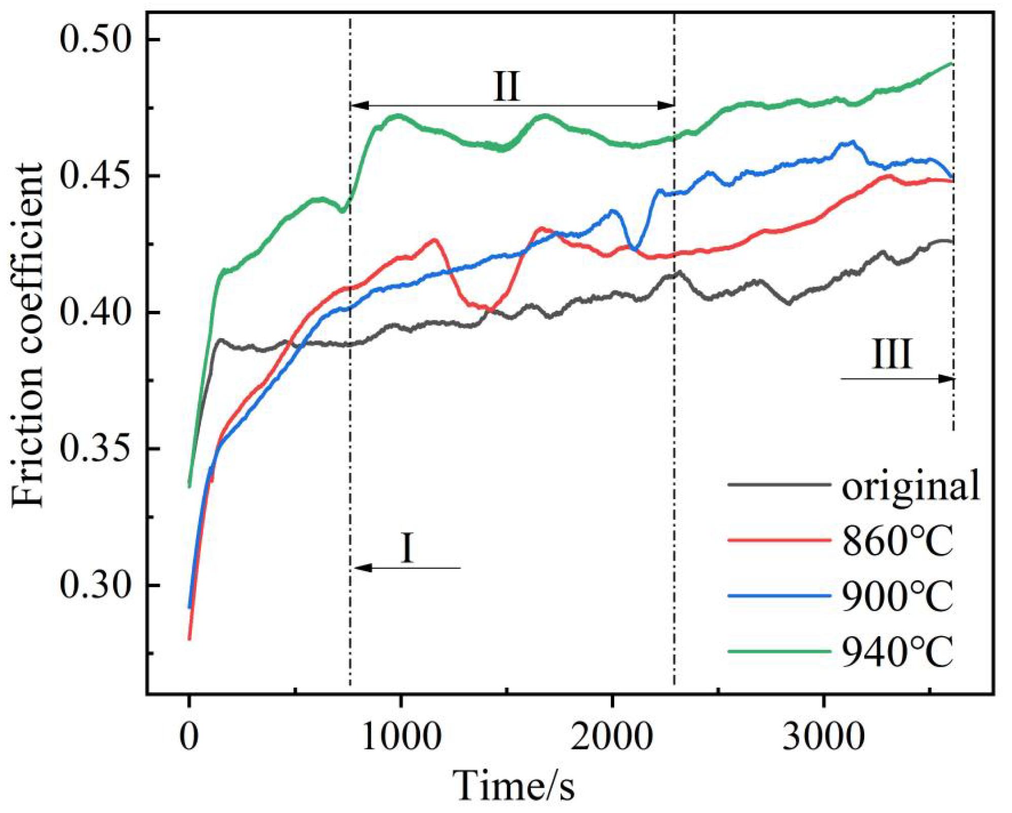
Figure 1 shows the sliding friction coefficient curve of the wear-resistant layer BTW1 (860 °C, 900 °C, 940 °C) and tungsten carbide ball of BTW1/Q345 composite plate with a depressive rate of 50% under dry friction conditions under different heat treatment temperatures. The trend of the friction factor in the figure with time shows that the friction factor of the sample first rises rapidly, then decreases to a certain extent, and then gradually increases, and finally reaches a zigzag fluctuation. In the initial wear stage, the friction factor shows an upward trend and fluctuates greatly, because at the beginning of the experiment, the surface of the friction pair is uneven, and the contact mode of the friction pair at the beginning of the sliding stage is point contact, the load per unit area is very large, and the dry friction is carried out, and the sliding friction surface is not lubricated, so the friction factor rises rapidly [
24]. After a period of friction, grinding chips are generated, and a large amount of grinding chips accumulate between the grinding pairs to play the role of solid lubrication, and the friction factor decreases slightly [
25]. As the friction continues, the grinding debris increases, and the hard abrasive debris is pressed into the friction surface under the normal action, resulting in a furrow and an increase in the surface contact area, resulting in an increase in the friction factor. The zigzag fluctuation in the stabilization phase is caused by the microstructural changes of BTW1. The matrix of BTW1 is austenite with excellent fracture toughness. In the process of friction and wear, austenite is in a metastable state, which is easy to induce phase transformation strengthening, micro alloy strengthening and dislocation deformation strengthening. As the hardened material surface wears out, the newly exposed surface also reinforces itself. Therefore, when the scraper of the scraper conveyor adopts BTW1 wear-resistant steel composite plate, the transportation of coal will cause wear on the scraper, and the wear strengthening mechanism of BTW1 can increase the service time of the scraper [
26].
As shown in
Figure 1, the friction factor of BTW1/Q345 composite plate wear-resistant layer BTW1 after annealing is higher than that before annealing, and the heat treatment temperature is 940 °C, and the friction factor is the highest.
Figure 1.
Sliding friction factor of BTW1/Q345 wear-resistant layer annealed at different temperatures at 50% reduction rate.
Figure 1.
Sliding friction factor of BTW1/Q345 wear-resistant layer annealed at different temperatures at 50% reduction rate.
3.1.2. Macroscopic Morphology and Cross-Sectional Curve of Wear Marks
The specimen and tungsten carbide balls, which are used for abrasive materials, are subjected to shear stress and compressive stress during sliding friction wear. Due to the different annealing temperatures of the materials, the material removal mechanism is also different in the process of friction and wear, resulting in different macroscopic morphologies of the wear marks.
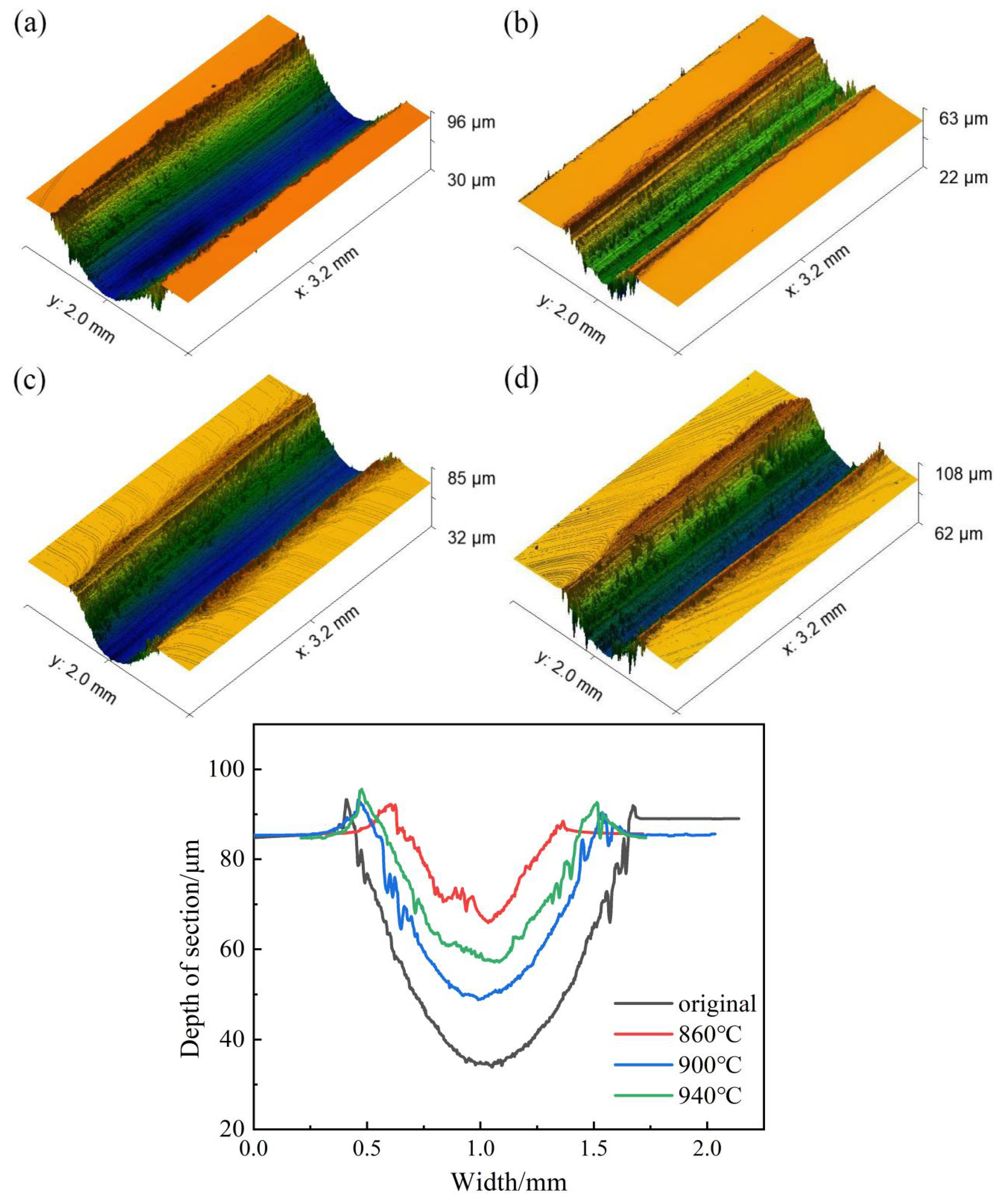
Figure 2 shows the three-dimensional morphology and scratch cross-section curve of the scratches on the wear surface of the specimen after the wear-resistant layer of the BTW1/Q345 composite plate is pressed at 50%, and the original surface is selected as the reference surface. The macroscopic topography of the middle part of the scratch can be seen from
Figure 2a–d, and the width and depth of different specimens can be seen from the legend.
Figure 2e provides a more intuitive view of the depth and width of the scratch at different annealing temperatures. It can be concluded that when the depressing rate is 50%, the maximum depth and width of the scratch of the unannealed specimen are 51 μm and the width is 1.35 mm, the maximum depth of the scratch is 20 μm and the width is 0.825 mm when the annealing temperature is 860 °C, the maximum depth of the scratch is 37 μm and the width is 1.125 mm when the annealing temperature is 900 °C, and the maximum depth of the scratch is 27 μm and the width is 1.025 mm when the annealing temperature is 940 °C.
Based on the topography results of
Figure 2, when the material is not annealed, the wear is the most severe, the maximum depth value is the largest, and the width is the widest. The annealing is completed at 860 °C, and the maximum scratch depth of the wear-resistant layer is 20 μm, and the width is 0.825mm, and the wear performance is the best.
Figure 2.
Three-dimensional Morphology and Section Curve of Abrasion Resistant Layer under Different Annealing Temperature: (a) original (b) 860 °C (c) 900 °C (d) 940 °C.
Figure 2.
Three-dimensional Morphology and Section Curve of Abrasion Resistant Layer under Different Annealing Temperature: (a) original (b) 860 °C (c) 900 °C (d) 940 °C.
3.1.3. Analysis of Wear Morphology and Mechanism
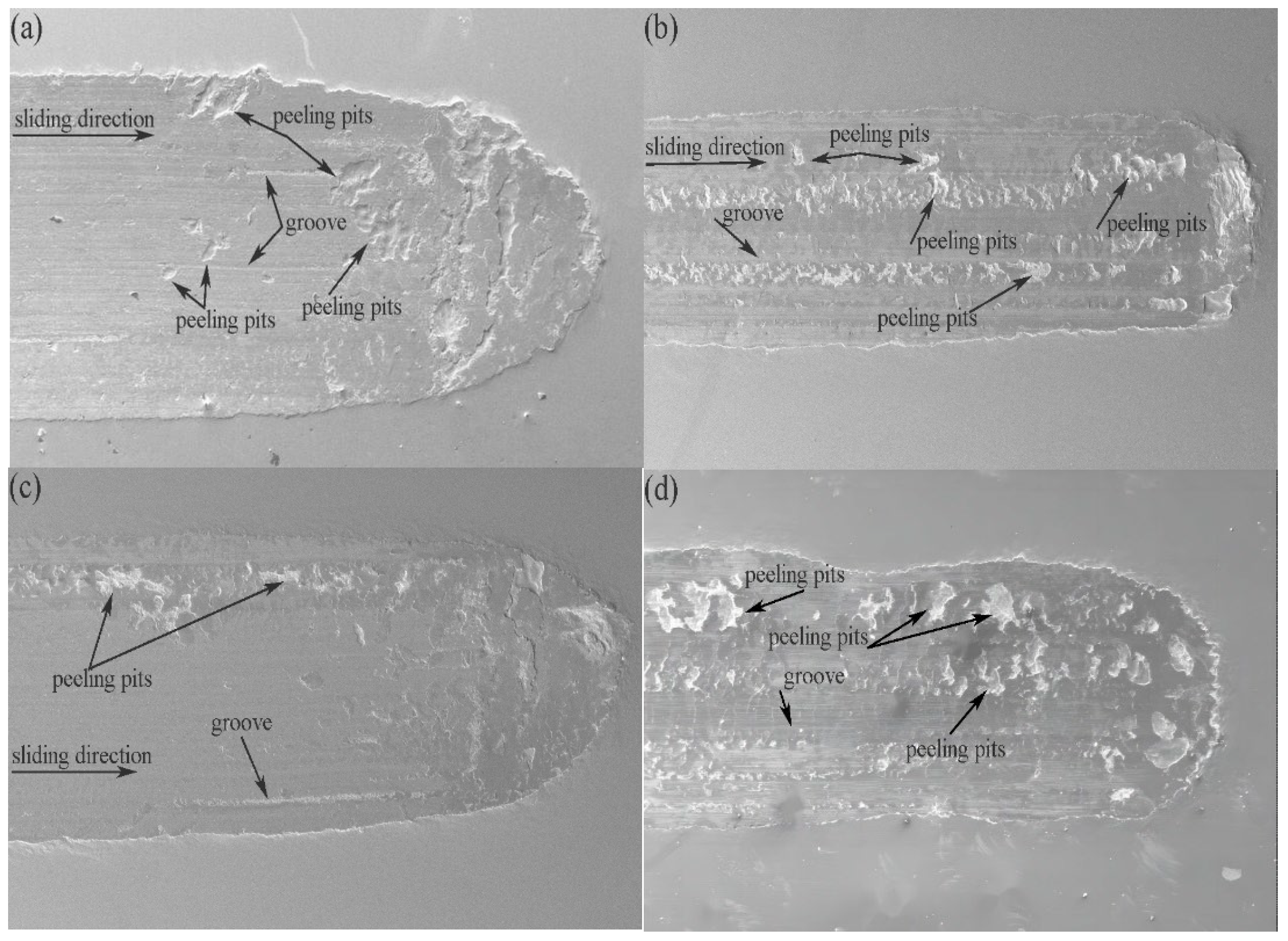
Figure 3 shows SEM morphology photos of different specimens subjected to sliding friction wear under a load of 200 N at room temperature. As shown in
Figure 3a, BTW1 without heat treatment has obvious plow groove scratches and local peeling pits. The plow groove deepens and widens compared to the annealed sample, and there is a peeling layer at the edge of the scratch, with obvious layering. A portion of the debris generated during the friction process still remains in the scratches. The debris cuts into the surface under normal load and forms plow grooves during sliding. The peeling pits on the worn surface belong to the characteristics of fatigue wear, which are the wear and peeling damage caused by local material fatigue under the action of contact force after abrasive is pressed into the worn surface. It can be seen that the wear mechanism has shifted from adhesive wear to plowing wear and fatigue wear. From
Figure 3b–d, it can be seen that there are small furrow scratches and large peeling pits on the surface of the sample. This is due to the adhesion between the debris and the contact surface during the wear process, which then accumulates on the worn surface and participates in friction, leading to intensified wear and the occurrence of peeling. A small plow groove is formed by the micro convex body between the contact surfaces and the abrasive debris cutting into the surface under normal force, and the high load provides a larger normal stress. When sliding, the surface produces cutting, thus forming a plow groove. The wear mechanism is mainly adhesive wear and fatigue wear.
In the early stage of wear, the micro convex bodies between the friction pair surfaces form local adhesion during the sliding process. Under the action of shear stress, the material in the adhesive part is sheared off. Due to the lack of lubrication, this adhesive wear is very severe in the early stage of wear. The debris increases to a certain extent and forms an intermediate layer. The debris and micro convex bodies cut into the surface under normal load, and when sliding, a plow groove is formed on the surface. Repeated plow groove cutting causes plastic deformation wear on the surface; In addition, due to the repeated movement of the peeling material, plastic deformation and fatigue failure occur, forming some transverse cracks in the shallow surface layer. The cracks gradually expand to connect with the vertical cracks at the grain boundary, thus forming fatigue peeling wear. Therefore, the dry friction wear mechanism shifts from adhesive wear to plastic deformation wear and fatigue peeling wear [
4].
Figure 3.
Dry friction wear morphology of wear layer BTW1 of composite plate under different annealing temperatures.
Figure 3.
Dry friction wear morphology of wear layer BTW1 of composite plate under different annealing temperatures.
3.2. Evolution of Microstructure after Wear
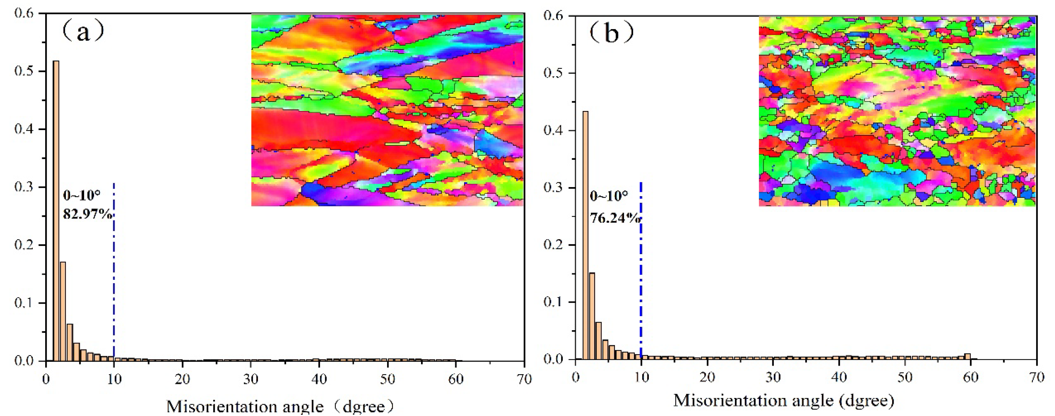
Figure 4 shows the distribution of grain orientation differences at various angles and the IPF (normal) direction in the vicinity of scratches in the original sample and after 860 °C heat treatment. The surface of the specimen is defined as the RD-TD plane, and the direction perpendicular to this plane is ND. Among them, RD is the x-axis, TD is the y-axis, and ND is the z-axis. In these IPF diagrams, different colors represent different crystal orientations. The red color indicates grains with an orientation<001>, which are parallel to the ND axis of the specimen coordinate system. Green represents grains with an orientation<101>parallel to the ND axis, while blue represents grains with an orientation<111>parallel to the ND axis of the specimen coordinate. In the original sample and the 860 °C heat treated sample, the main color range of the original sample is red green, accompanied by some blue purple particles. The results indicate that austenite mainly exhibits preferential orientation along the 001 and 101 directions. It can be observed that compared with the sample heat-treated at 860 °C, the red particles in the sample annealed at 860 °C are significantly reduced, with a larger proportion of green particles accompanied by some blue particles. The dispersed blue particles indicate a certain degree of preferred orientation along the 111 directions. The results indicate that as the heat treatment temperature increases, the preferred orientation of grains changes, which is reflected macroscopically as a change in the main crystal orientation.
Based on the statistical results in
Figure 4, the occurrence frequency of grain boundary of original manganese steel sample and 860 °C grain boundary of BTW austenite in the range of 0~10° is 82.97% and 76.24% respectively. It can be found that most grain boundaries near the wear mark are concentrated in the small angle range of 0~10°. With the increase of annealing temperature, the proportion of small-angle grain boundary gradually decreases, and the proportion of large-angle grain boundary gradually increases, which is caused by the increase of annealing temperature and recrystallization state. It can also be found that the percentage of orientation difference at 60° for BTW increases with increasing annealing temperature. This angle can be seen as a typical twin structure produced by the annealing process for a face-centric cubic crystal structure. With the increase of twin, the metal matrix is cut into more small pieces. The more the twin boundary is, the greater the sliding resistance is, the higher the metal is reinforced [
27].
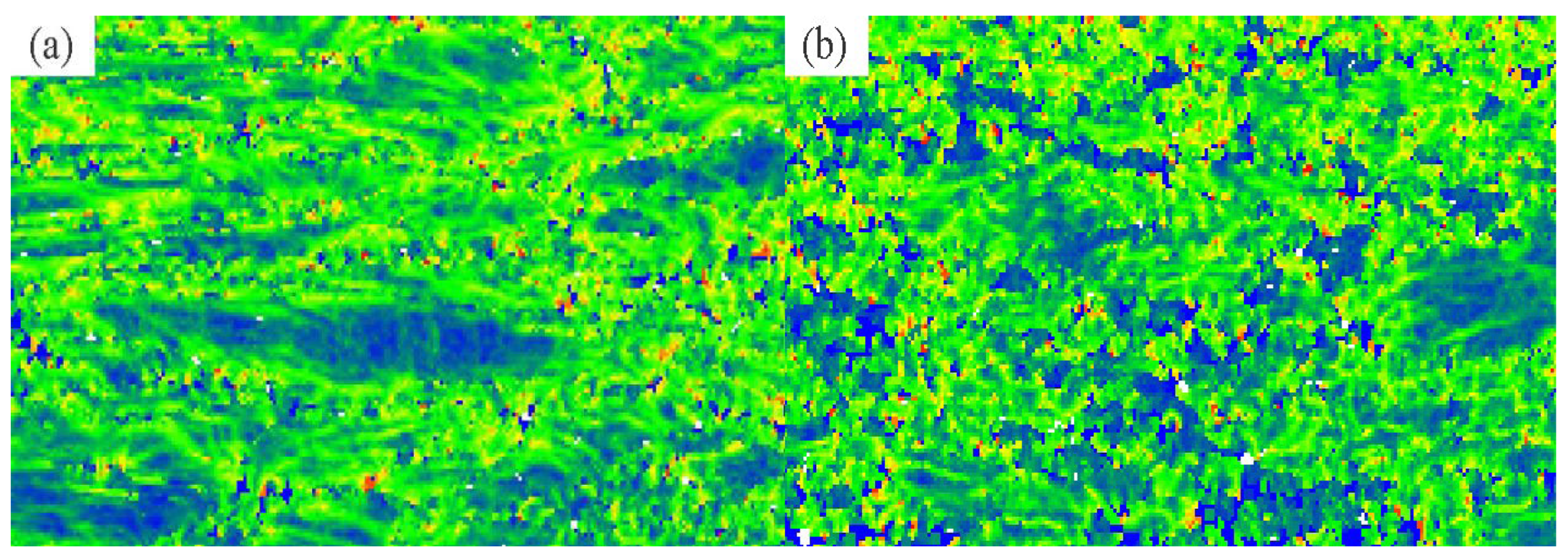
Figure 5 shows the nuclear average orientation difference (KAM) plot for the sample. These plots are generated by calculating the orientation deviation between adjacent particles. The KAM value can quantify the geometric dislocation density theoretically and reflect the uniformity degree of plastic deformation. Higher values indicate increased plastic deformation or increased defect density. In the KAM diagram, the darker the color, the higher the defect density. Blue for value 0, red for maximum distortion value 5. In contrast, the color of the original sample is dominated by green, and the high value of nuclear average orientation difference (KAM) means that more dislocation formation is induced during rolling. At the annealing temperature of 860 °C, the color is mainly blue-green, and the average orientation difference (KAM) value of the core is lower than that of the original sample. The results show that the dislocation density of annealed samples is lower than that of original samples. From
Figure 5, it can be seen that when the sample is not annealed and the load is 200N, the residual stress of the sample is high, the dislocation is easy to accumulate, and the KAM value is high. The KAM value of the sample decreases and the residual stress value is small after annealing.
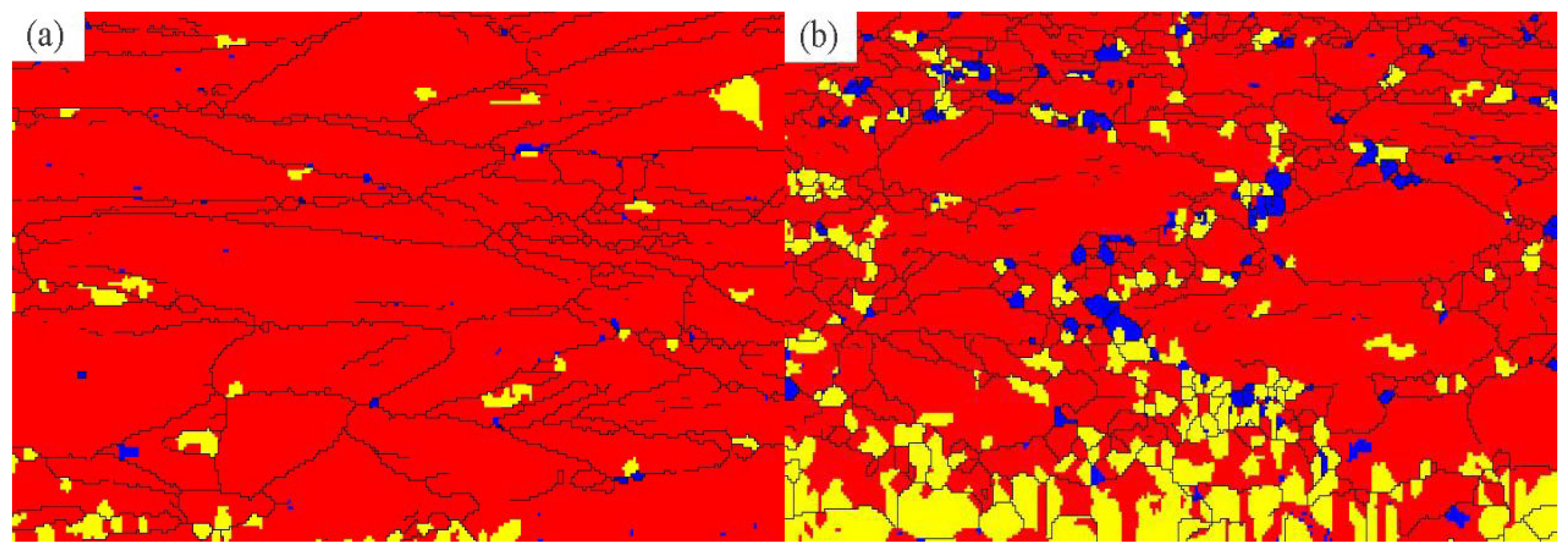
Figure 6 shows the recrystallization distribution in the area near the scratch. Among them, red represents deformed grain, yellow represents recovered grain and blue represents recrystallized grain. It can be seen that in the original and annealed samples, the red deformed grains account for most of the area and the blue recrystallized grains account for a small proportion in the original samples. When the annealing temperature is 860 °C, the proportion of blue recrystallized grain and yellow recovered grain is higher than that of original sample, and the proportion of red deformed grain is lower than that of original sample, so the recrystallization degree of sample is better. A large amount of dislocation will be introduced into the matrix after the rolling of medium manganese steel, which makes the medium manganese steel easy to induce recrystallization in the annealing process, forming the equiaxed duplex structure composed of ultra-fine grain ferrite and residual austenite [
28,
29]. Through the recrystallization regulation at different temperatures, the formation of diversified residual austenite can make the medium manganese steel obtain higher work hardening. Through the recrystallization regulation at different temperatures, the formation of diversified residual austenite can make the medium manganese steel obtain higher work hardening [
30].
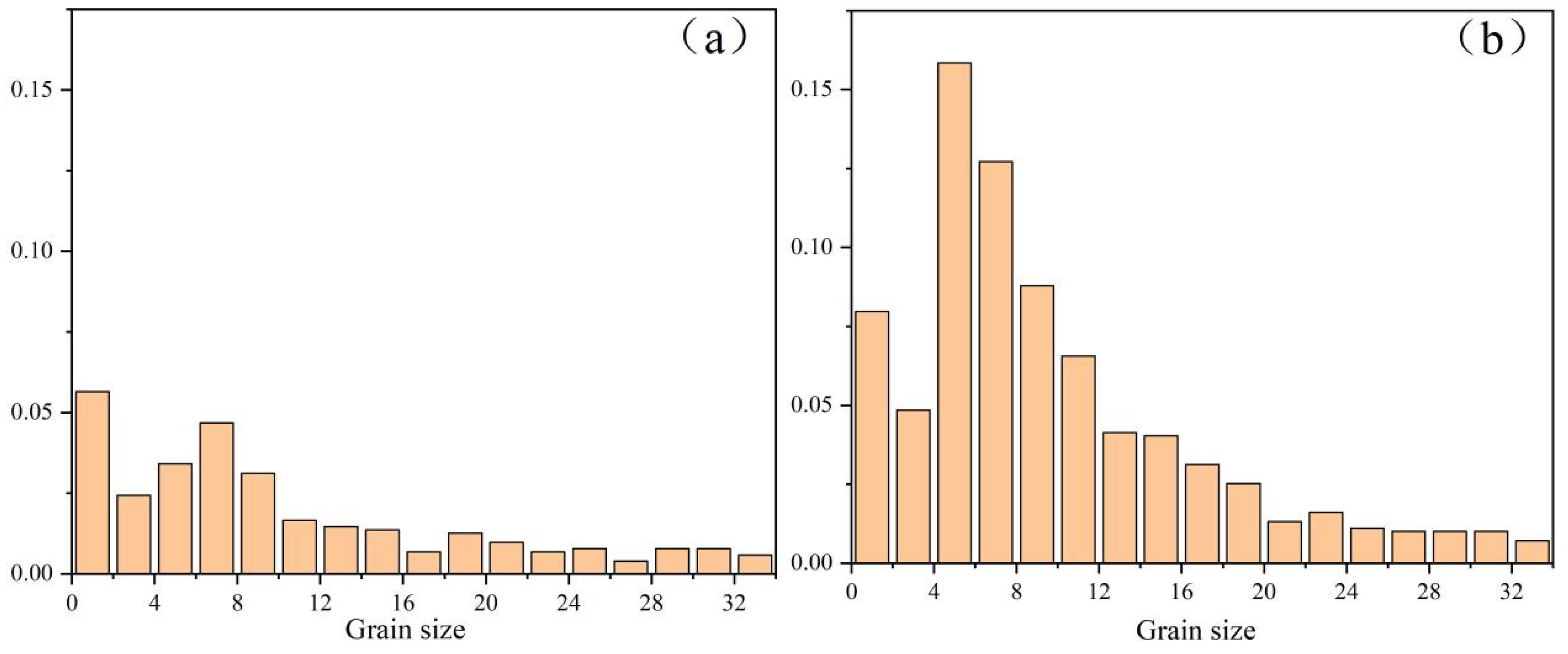
The statistical distribution diagram of EBSD grain size can reflect the statistical distribution of grains in each size. The distribution proportion of grains in each size can be clearly seen through it. It is of great significance to control grain size and structure uniformity.
Figure 7 is the statistical distribution diagram of grain size of original samples and samples after annealing at 860 °C. It can be clearly seen that the grain refinement process with the change of annealing temperature: the proportion of small grains in the original sample without annealing treatment is small, and the proportion of small grains in the original sample is higher at the annealing temperature of 860 °C. Based on the recrystallization structure diagram in
Figure 6, it can be concluded that with the increase of annealing temperature, the grain is refined continuously, and the uniformity of structure is improved significantly. The crystal interface is the impediment to dislocation movement. Therefore, the finer the grain is, the more the grain boundary is, the more the dislocation is blocked, and the higher the strength of polycrystalline. Grain refinement improves the work-hardening properties of manganese steels, and the subsurface usually exhibits better tribological properties [
31].
4. Conclusions
The effect of different annealing treatments on the wear performance of hot-rolled wear-resistant steel BTW1/Q345 composite plates was studied. The results indicate that:
(1) The friction coefficient change of the wear-resistant layer BTW1 in the friction and wear test is divided into 3 stages. The friction coefficient rises rapidly at the initial stage of running-in and then drops to some extent. Finally, in the third stage, the friction coefficient fluctuates within a certain range.
(2) During the experiment, the wear mechanism changed somewhat, mainly for adhesive wear and fatigue wear. When the annealing temperature is 860 °C, the maximum depth and width are the minimum, 20 μm and 0.825 mm, respectively, with the best wear resistance.
(3) With the increase of annealing temperature, the orientation difference of wear layer BTW1 varies. Compared with the original sample, the small angle grain boundary angle ratio of annealed sample decreases, and the large angle grain boundary angle ratio increases. Small angle grain boundary angle decreases with increasing annealing temperature.
(4) With the increase of annealing temperature, the recrystallization state and grain size of the sample change. The recrystallization degree of annealed sample is higher than that of original sample, the proportion of small grain increases, the microstructure of wear-resistant layer is refined, and the working hardening property of wear-resistant layer is improved.
Author Contributions
Conceptualization, Pengtao Liu; Methodology, Formal Analysis, Investigation, Writing—Original Draft, Resources, Pengtao Liu; Formal Analysis, Investigation, Writing—Original Draft, Lei Huang; Resources, Ke Wang; Conceptualization, Wenjun Meng; Resources, Zhixia Wang; Validation, Lei Huang. All authors have read and agreed to the published version of the manuscript.
Funding
The study was financially supported by the Fundamental Research Program of Shanxi Province (20210302124446), the Taiyuan University of Science and Technology Scientific Research Initial funding (20212008), the Excellent Doctor Award Fund for working in Shanxi (20212073).
Acknowledgments
The authors gratefully acknowledge the technical support of the Taiyuan University of Science and Technology.
Conflicts of Interest
The authors declare no conflicts of interest.
References
- Tang, L.-l. Performance characteristics and application field of high chromium wear composite plate. Opencast Mining Technology 2011, 27, 82–83. [Google Scholar]
- Zhang, J.-z.; Mi, G.-f.; Guan, X.-z. Application and research on low-alloyed wear resistant cast steel. MW Metal Forming 2009, 15, 29–31. [Google Scholar]
- Zhao, G.-h.; Zhang, J.; Song, Y.-h. Friction and Wear Properties of Wear-Resistant Layer of NM500/Q345 Composite Plates at Different Quenching Temperature. Journal of Netshape Forming Engineering 2021, 013, 35–41. [Google Scholar]
- Wang, F. Study on the Tribology Performance of BTW Medium Manganese Wear Resisting Steel. China University of Mining and Technology 2015, 25, 21–42. [Google Scholar]
- GARCIA DE ANDRES, C.; CAPDEVILA, C.; SAN MARTIN, D. Effect of titanium on the allotriomorphic ferrite transformation kinetics in medium carbon–manganese steels. Materials Science and Engineering 2002, 328, 156–160. [Google Scholar] [CrossRef]
- Xu, B.-s.; Liu, S.-c. New technologies for surface engineering. National Defense Industry Press: Bei Jing, 2002; Volume 32, pp. 1–12. [Google Scholar]
- Qiu, X.-w.; Zhang, Y.-P.; Chun, G.-l. Study on Ware Resistance of Laser Hardening Rolling Mill Liner. Applied Mechanics and Materials 2012, 121–126, 3551–3554. [Google Scholar] [CrossRef]
- Wang, s.; Zhi, B.-z.; Jun, L.-j. Recent advances in wear-resistant steel matrix composites: A review of reinforcement particle selection and preparation processes. Journal of Materials Research and Technology 2024, 1779–1797, 2238–7854. [Google Scholar] [CrossRef]
- Li, L.; Chen, M.-y. Production Technologies and Industrial Application of Wear Resistant Clad Steel Plate. Wide and Heavy Plate 2016, 22, 38–43. [Google Scholar]
- Arlazarov, A.; Gouné, M.; Bouaziz, O. Evolution of microstructure and mechanical properties of medium Mn steels during double annealing. Materials Science & Engineering 2012, 542, 31–39. [Google Scholar]
- Luo, H.; Shi, J.; Wang, C. Experimental and numerical analysis on formation of stable austenite during the intercritical annealing of 5Mn steel. Acta Materialia 2011, 59, 4002–4014. [Google Scholar] [CrossRef]
- Cai, Z.-h.; Ding, H.; Xue, X. Microstructural evolution and mechanical properties of hot-rolled 11% manganese TRIP steel. J. Materials Science & Engineering 2013, 560, 388–395. [Google Scholar]
- Zhao, J.; Xi, Y.; Shi, W. Microstructure and Mechanical Properties of High Manganese TRIP Steel J. Journal of Iron and Steel Research International 2012, 19, 57–62. [Google Scholar] [CrossRef]
- Yang, Y.-g.; Luo, X. Microstructure evolution and strengthening mechanism of air-hardening steel subjected to the austenitizing annealing treatment. Materials Research Express 2023, 10, 106502. [Google Scholar] [CrossRef]
- Emmanuel, D.M.; Gordon, S.J.; Kidder, M.D. Effect of Carbon and Manganese on the Quenching and Partitioning Response of CMnSi Steels. Isij International 2011, 51, 137–144. [Google Scholar]
- Dong, W.S.; Ryu, J.H.; Min, S.J. Medium-Alloy Manganese-Rich Transformation-Induced Plasticity Steels. J. Meta llurgical & Materials Transactions 2013, 44, 286–293. [Google Scholar]
- Li, N.; Shi, J.; Chen, W.-l. Effect of Carbon Content on Microstructure and Mechanical Properties of Cold-rolled Medium Manganese Steel. Hot Working Technology 2012, 41, 5–8. [Google Scholar]
- Grajcar, A.; Kwany, W. Microstructural study on retained austenite in advanced highstrength multiphase 3Mn-1.5Al and 5Mn-1.5Al steels. Journal of Achievements in Materials & Manufacturing Engineering 2012, 54, 168–177. [Google Scholar]
- Aydin, H.; Essadiqi, E.; Jung, I.H. Development of 3rd generation AHSS with medium Mn content alloying compositions. Materials Science & Engineering A Structural Materials Properties Microstructure & Processing 2013, 564, 501–508. [Google Scholar]
- Zhi, C.-c.; Ma, L.-f.; Huang, Q.-x. Effect of Reduction on Bonding Interface of Hot-rolled Wear-resistant Steel BTW1/Q345R Cladding Plate. J. Journal of Wuhan University of Technology-Mater Sci Ed. 2018, 33, 952–958. [Google Scholar] [CrossRef]
- Bai, Z.-x.; Su, N.; Hang, Y. Wear characteristics of austenitic steel and martensitic steel at high temperature. Materials Research Express 2022, 9, 086504. [Google Scholar] [CrossRef]
- Ge, S.-r.; Wang, J.-x.; Wang, Q.-l. Self-strengthening wear resistant mechanism and application of medium manganese steel applied for the chute of scraper conveyor. Journal of China Coal Society 2016, 41, 2373–2379. [Google Scholar]
- Miao, C.-w.; GUO, Z.-w.; Yuan, C.-q. Coupling Mechanism and Friction Reduction Performance of Textured Cylinder-Piston Ring. Surface Technology 2020, 49, 124–133. [Google Scholar]
- Mo, D.-y.; Gong, M.-f.; Wu, H.-b. Surface Modification of 5Cr5MoWSi Steel and Tribological Properties. Machinery Design & Manufacture 2020, 012, 000. [Google Scholar]
- Zhang, H.-m. Study on friction and wear characteristics of GCr15/45# steel under lubrication conditions. Southwest Jiaotong University 2010, 35, 5525. [Google Scholar]
- Liu, P.-t.; Huang, Q.-x. Characterization of hot deformation behavior of wear-resistant steel BTW1 using processing maps and constitutive equations. Journal of Iron and Steel Research International 2018, 25, 1054–1061. [Google Scholar] [CrossRef]
- Chen, H. Study on the wear properties and strengthening mechanism of manganese steel in deformation-induced hardening austenite. China University of Mining and Technology 2023, 36, 11–30. [Google Scholar]
- Astafurova, E.-G.; Tukeeva, M.-S.; Zakharova, G.-G. The role of twinning on microstructure and mechanical response of severely deformed single crystals of high-manganese austenitic steel. Materials Characterization 2011, 62, 588–592. [Google Scholar] [CrossRef]
- Karaman, I.; Sehitoglu, H.; Gall, K. Deformation of single crystal Hadfield steel by twinning and slip. Acta Materialia 2015, 48, 1345–1359. [Google Scholar] [CrossRef]
- Hu, B.-j.; Zhen, Q.-y.; Lu, T. Recrystallization Controlling in a Cold-Rolled Medium Mn Steel and Its Effect on Mechanical Properties. Acta Metallurgica Sinica 2024, 60, 189–200. [Google Scholar]
- Xia, W.-z.; Patil, P.-P.; Chang, L. A novel microwall sliding test uncovering the origin of grain refined tribolayers. Acta materialia 2023, 246, 118670. [Google Scholar] [CrossRef]
|
Disclaimer/Publisher’s Note: The statements, opinions and data contained in all publications are solely those of the individual author(s) and contributor(s) and not of MDPI and/or the editor(s). MDPI and/or the editor(s) disclaim responsibility for any injury to people or property resulting from any ideas, methods, instructions or products referred to in the content. |
© 2024 by the authors. Licensee MDPI, Basel, Switzerland. This article is an open access article distributed under the terms and conditions of the Creative Commons Attribution (CC BY) license (http://creativecommons.org/licenses/by/4.0/).
