1. Introduction
Soft magnetic composite materials (SMCs) have been of great research and application interest for several decades. These types of magnetic materials hold promise for better soft magnetic materials that can operate at high frequencies (implying high electrical resistivity) with very good magnetic characteristics such as inductance and permeability. The usual way to produce such a composite consists of coating the ferromagnetic particles with a thin layer of dielectric material and then compacting the particles by powder metallurgy techniques [
1,
2,
3,
4,
5,
6,
7].
Soft magnetic composite materials (SMC) are produced by powder metallurgy from soft ferromagnetic powders pressed together with an organic or inorganic dielectric binder. Several different Fe, Fe-Ni, Fe-Si, Fe
3P, Fe-Si-Al, Mo-Permalloy powders have been used as ferromagnetic phase [
8,
9,
10,
11]. As a dielectric binder, it can be use either an organic dielectric (epoxy resin, elastomers, etc.) or an inorganic binder (phosphates, oxides, glass, and so on) [
10].
One of the new classes of soft magnetic materials is alloy/ferrite composites [
12]. The aim of producing soft magnetic composites from alloy and ferrite is to obtain a material with an electrical resistivity closer to that of ferrite and a magnetic induction closer to that of the alloy. The use of soft magnetic ferrite material as a coating agent can also improve the application frequency of Fe-based SMCs because the coating layer has high frequency stability [
13,
14].
In addition to its interesting characteristics, this type of composite material is also attractive due to the low cost of basic raw materials such as iron and hematite [
15,
16]. Extremely important is the insulating phase, which determines the density, mechanical properties, electrical resistivity and essentially all magnetic properties of SMCs. MnZn ferrite, NiZn ferrite and Ni ferrite have high resistivities [
14] and also good magnetic properties. The most obvious advantage of these coatings is the reduced number of air gaps between the metal powder particles, these air gaps lead to effectively reducing the magnetic material’s saturation magnetisation and permeability. In addition, ferrite is a soft magnetic material that can be used at higher temperatures and frequencies [
17,
18].
An interesting approach to obtain SMCs can be to use the ferromagnetic particles having a dielectric layer formed by ferrites and compacting by Spark Plasma Sintering (SPS). The densification of the alloy/ferrite composite powders by SPS can be difficult due to the possibility to have a reaction between the composite phases. To avoid this reaction, the sintering parameters should be chosen very carefully. The sintering time in SPS technique are very short and the sintering temperature is lower than in classical sintering. These parameters help to avoid reactions between the composite particle phases during the sintering process [
14,
18,
19,
20,
21,
22,
23].
The paper presents results concerning producing and characterising Permalloy (Supermalloy)@ZnFe2O4 pseudo-core-shell particles and soft magnetic composite compacts from as-obtained powders produced via the spark plasma sintering densification technique. Our approach is to obtain soft magnetic composites of a Ni-based alloy in a zinc ferrite (ZnFe2O4) resistive matrix. The zinc ferrite shell of the pseudo-core-shell particles will create a network structure that will assure an enhanced electrical resistivity after sintering in the Ni3Fe/ZnFe2O4 and Supermalloy/ZnFe2O4 type soft magnetic composite. This procedure is a new and simple route that involves an accessible way to cover the Ni-based ferromagnetic particles with a thin layer of zinc ferrite particles, and it uses a low-energy densification technique. The SMC with ferromagnetic Ni-based particles and ferrite as dielectric was obtained by SPS until now, but such a combination of precursors to our knowledge it has not been used before.
2. Materials and Methods
Nanocrystalline soft magnetic Permalloy (Ni3Fe) and Supermalloy (79Ni16Fe5Mo, wt. %) were achieved by mechanical alloying using elemental powders: Fe (NC 100.24, purity 99.85 %, produced by Höganäs AB, Höganäs, Sweden), Ni carbonyl 123 (purity 99.9 %, Alpha Aesar, Kandel, Germany) and Mo (purity 99.95 %, Alpha Aesar, Kandel, Germany) obtained by chemical reduction. Mechanical alloying was carried out for up to 12 hours in a planetary ball mill manufactured by Fristch, model Pulverisette 6 (Idar-Oberstein, Germany). The alloying/milling process was performed in a high-purity argon atmosphere using a 500 ml vial and 14 mm diameter balls. The 12 h mechanically alloyed powder was annealed at 350 °C for 4 h to remove the internal stresses induced by the milling process and to ensure that the solid-state reaction to form Ni3Fe intermetallic compound as a single phase is finished.
Nanocrystalline Ni3Fe and Supermalloy powders obtained by mechanical alloying after 12 h of milling and ZnFe2O4 powders have been used to produce pseudo-core-shell powders, which consist of a core of very large Ni3Fe or Supermalloy particles covered by a discontinuous layer (shell) of Zn ferrite. The ferrite particles have the chemical formula ZnFe2O4 and were supplied by Alfa Aesar of Johnson Matthey Company, Germany. The Zn ferrite particles size is less than 10 µm. The amount of 5 wt% of zinc ferrite was calculated to result in a volume percentage of ferrite in the mixture of about 10 vol.%.
The resulting mixtures were homogenised for 15 minutes a Turbula-type spatial homogeniser to ensure the most uniform distribution of particles. Due to the difference in particle size between Ni3Fe and Supermalloy powders on one side and Zn ferrite powder (much finer) on the other side, the result was alloy powder particles coated with a fine layer of ferrite particles.
The pseudo-core-shell Permalloy (Supermalloy)@ZnFe
2O
4 composite particles were subjected to densification by spark plasma sintering (SPS), using a home-made equipment [
14,
19,
22,
24]. SPS process was performed in a graphite die by applying a pulsating current to the powders of maximum intensity 2,500 A in an argon atmosphere and the sintering chamber is cooled by water pipes. The sintering process was done in an argon atmosphere to prevent additional oxygen in the samples and to protect the die and punches. A constant pressure of 30 MPa was kept during the heating-sintering and cooling cycle. In the heating sequence, the temperature heating rate was approximately 5 °C/s. The powders were sintered at temperatures of 500, 600, 650 and 700 ℃, and the holding time at the sintering temperature was zero minutes. That means that the samples were only heated to the established temperature, the current was cut, and the cooling process down to room temperature followed. The cylindrical-shaped samples produced by SPS were drilled for toroidal shaping. Before drilling, the sintered compacts were metallographically conditioned using silicon carbide sandpaper and alumina solution. The so obtained toroidal-shaped samples were wired with 0.5 mm (for primary coil) and 0.35 mm (for secondary coil) copper wire.
The formation of Permalloy and Supermalloy alloys by mechanical alloying, as well as the phase retention in sintered compacts, were studied by X-ray diffraction using the INEL 3000 Equinox diffractometer, operating with radiation CoKα (1.79026 Å) in the angular range 2 θ= 20 - 110 degrees. The INEL 3000 Equinox diffractometer works in reflection mode and has a curved detector which simultaneously covers 90 degrees. The mean crystallite size was calculated for the annealed samples by the Scherrer method from the full-width-at-half-maximum (FWHM) of the diffraction peaks [
25]. In order to do so, a reference Ni sample was used to determine the resolution of the diffractometer. The morphology of the powders and the microstructure of the sintered compacts were investigated by scanning electron microscopy (SEM). A JEOL-JSM 5600-LV was used, working with the secondary electron signal. The JEOL JSM 5600-LV microscope is equipped with an Oxford Instruments EDX detector, model ULTIMMAX65 and Aztec analysis software. X-ray microanalysis was used to determine the chemical homogeneity of mechanically alloyed powders as well as local chemical analysis and phase identification (by chemical element distribution maps) in composite powders and compacts. The density of composite compacts was obtained by determining the mass and geometric dimensions of cylindrical compacts (diameter and height). The electrical characteristics were investigated with an electrical resistivity measuring system, which involves determining the electrical resistance on sintered compacts fixed between 2 flat contacts applied to the bases of cylindrical compacts. The SPS-ed composite compacts were magnetically characterised in DC and AC regimes. A computer-controlled hysteresisgraph Magnet-Physik Dr. Steingroever GmbH, Rema-graph–Remacomp C–705 model (Cologne, Germany) was used to register hysteresis curves. The AC tested frequency was ranged between 50-10,000 Hz, and the induction level was seated at 0.01 T.
3. Results and Discussions
3.1. Permalloy, Supermalloy and Permalloy (Supermalloy)@ZnFe2O4 Powders
The obtaining of Permalloy (Ni
3Fe) and Supermalloy (79Ni16Fe5Mo, wt.%) by mechanical alloying used in this study was detailed in our previous papers [
25,
26]. It was proved that the Ni
3Fe phase is obtained gradually by up to 8 h of milling. Up to 2 h of milling, the (200) and (211) diffraction peaks of Fe are visible in the patterns. Also, the asymmetry of the (200) and (220) maxima of Ni are visible at this milling time, and this asymmetry proves the presence of some Ni3Fe germs in powder. The milling was continued up to 12 h to ensure the reaction was finalised in the entire sample volume, knowing that X-ray diffraction could not reveal the small residual phases [
25].
Concerning the Supermalloy powders, it was shown in Ref [
26] that after 8 hours of milling, the Supermalloy is obtained as a single phase in the milled sample. The progressive Supermalloy formation during milling is due to the energy transfer from the milling balls to the powders. Thus, changes in the XRD patterns show the progressive disappearance of the Fe and Mo Bragg peaks and the displacement of the Ni Bragg peaks to lower diffraction angles at the positions of the Supermalloy maxima [
26].
The mean crystallite size of Ni
3Fe and Supermalloy powders is around 16-18 ± 2 nm. The other details about obtaining Permalloy and Supermalloy powders by mechanical alloying can be found in our previous papers in this field [
27,
28,
29,
30,
31,
32,
33].
Nanocrystalline Ni
3Fe and Supermalloy powders obtained by mechanical alloying after 12 h of milling and ZnFe
2O
4 powders have been used to produce pseudo-core-shell powders. By homogenisation, the very small particles of Zn ferrite cover more large particles of Ni
3Fe and Supermalloy. The result is pseudo-core-shell particles, which consist of a core of very large Ni
3Fe or Supermalloy particles covered by a discontinuous layer (shell) of fine Zn ferrite,
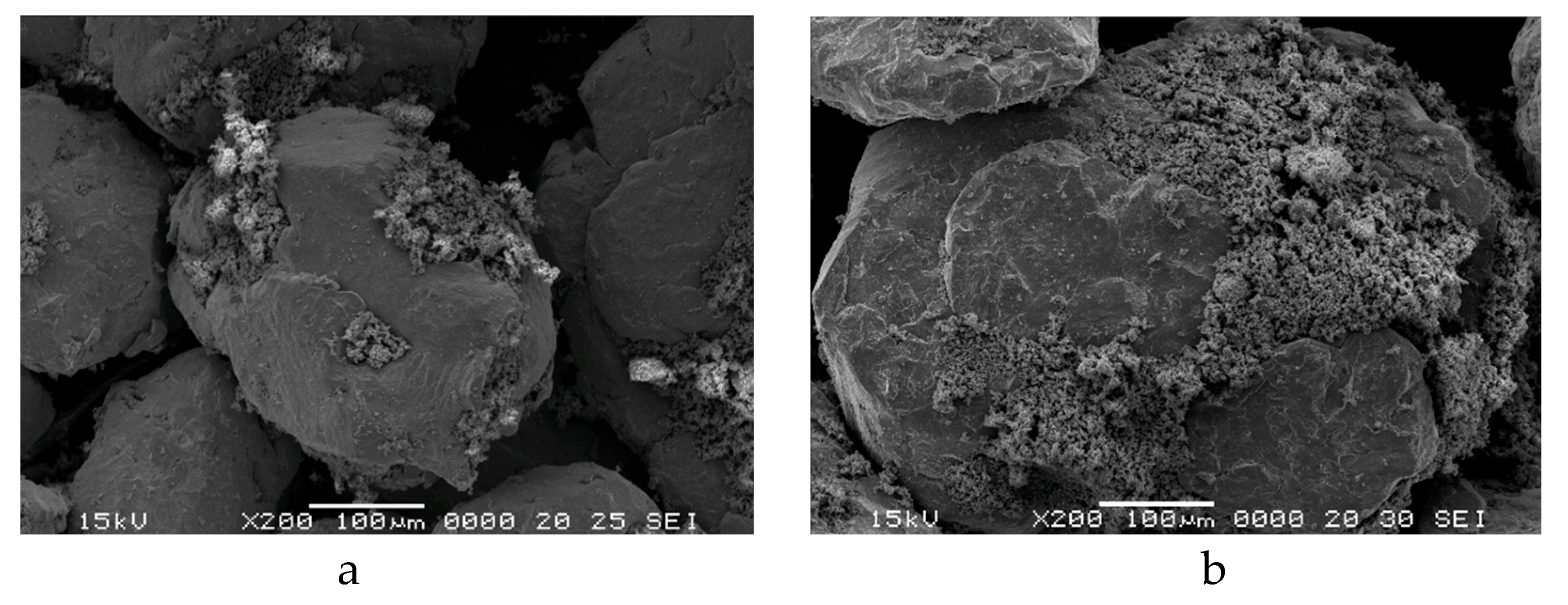
Figure 1. The adherence of the fine zinc ferrite particles on the surface of permalloy/supermalloy larger particles is enhanced by the roughness surface provided upon producing the particles by mechanical alloying. All the pseudo-core-shell particles have an irregular shape and their size ranges from a few dozen to a few hundred micrometres. The pseudo-core shell powder prepared, as mentioned, maintains that structure during powder manipulation for analysis and further use in producing SPS compacts. It is worth mentioning that the powder consists of core-shell structured particles and some zinc ferrite fine particles. The free (unattached) zinc ferrite particles help upon densifying to better insulate the particles, surface zinc ferrite discontinuous zones of core-shell particles are better covered.
3.2. Permalloy (Supermalloy)@ZnFe2O4 Compacts Prepared by SPS
The Ni
3Fe@ZnFe
2O
4 and Supermalloy@ZnFe
2O
4 pseudo-core-shell powders were compacted by SPS at 500, 600, 650 and 700 °C without holding time.
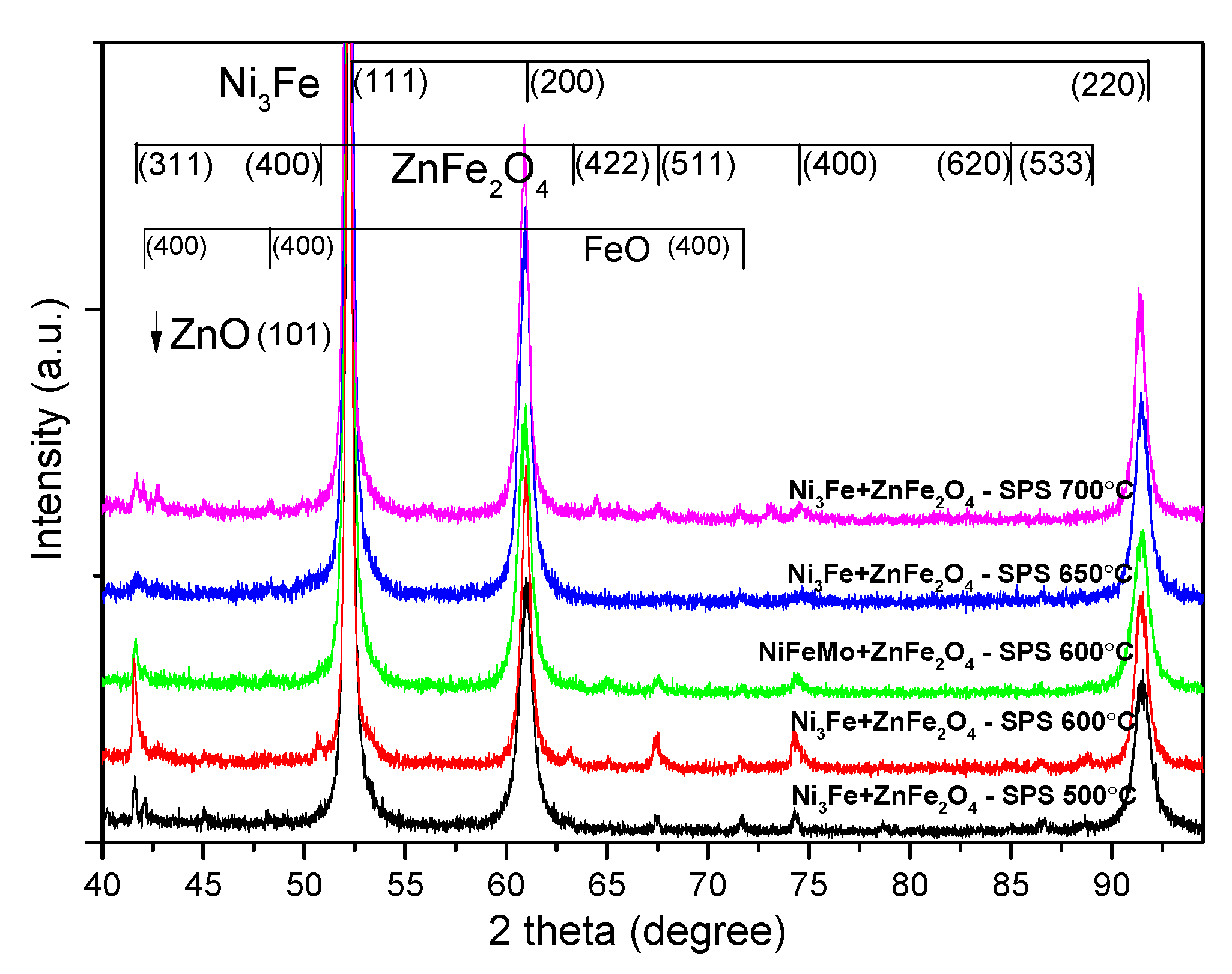
Figure 2 presents the X-ray diffraction patterns for the SPS-ed composite compacts produced from Ni
3Fe@ZnFe
2O
4 pseudo-core-shell powders. The Ni
3Fe FCC structure reflections are present in the patterns for all the samples. Upon increasing the sintering temperature, a decrease of the FWHM occurs, thus indicating the crystallite size increases. It can be observed the formation of new phases, as it is showed by the presence of new diffraction maxima. The newly formed phases that are present in compacts are identified as being FeO and ZnO. We can assume that this new phase forms at the interface between the metallic Permalloy and the zinc ferrite older phases by solid-state reactions. These new phases are expected to play a key role in the SPS-ed composite compact characteristics. Both phases that are formed upon sintering have high resistivity, and their presence is a positive aspect related to electrical resistivity. As the sintering temperature increases the intensity of the maxima of the newly phases increases, thus indicating the larger amount of these phases in the composite. Indeed, upon increasing the temperature, a higher mobility of the atoms is assured, and the iron atoms diffuse to the outer layer of the metallic particles and react with zinc ferrite, leading to partial decomposition.
The surface of SPS-ed composite compacts, obtained from Ni
3Fe@ZnFe
2O
4 pseudo-core-shell powders, are shown in
Figure 3. The density of the SPS-ed compacts increases by increasing the sintering temperature. Also, the porosity decreases by increasing the sintering temperature from 500 to 700 °C. The pores are smaller and less visible in the sample sintered at 700 °C compared to the others. The samples’ microstructure consists of metallic zones embedded in an almost continuous matrix/network, which are thinner when the sintering temperature increases. The matrix is connected to the shell formed by Zn ferrite of the Ni
3Fe@ZnFe
2O
4 pseudo-core-shell particles.
In order to evaluate the samples from the point of view of phase distribution, distribution maps of the constituent elements were recorded, following the ferrite distribution in relation to the soft magnetic phase (Ni3Fe),
Figure 4. The X-ray microanalysis (EDX investigations) confirm the above-described microstructures and phases distribution. The nickel-rich zones, provided by the Ni3Fe phase, are embedded in a quasi-continuos matrix formed the Fe, O and Zn elements, provided by zinc ferrite of the Ni3Fe@ZnFe2O4 pseudo-core-shell particles.
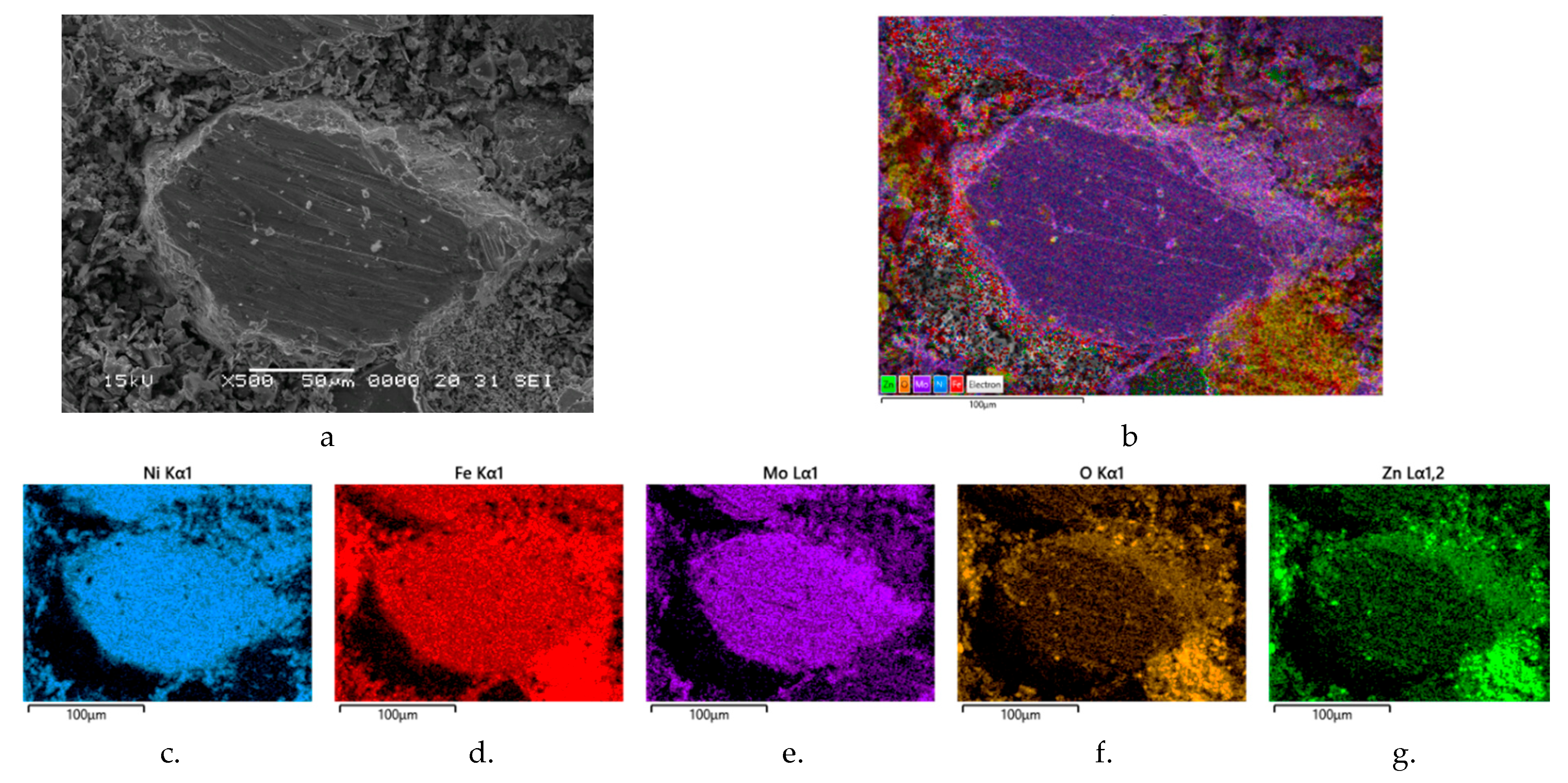
The same distribution of the phases (soft magnetic phase – Supermalloy and Zn ferrite) are evidenced also for the SPS-ed compacts obtained from Supermalloy@ZnFe
2O
4 pseudo-core-shell particles,
Figure 5. In
Figure 5a is shown a SEM image of the compact microstructure, and in
Figure 5b is shown the all elemental distribution maps superimposed on the SEM image from
Figure 5a;
Figure 5c–g show the individual distribution maps for Ni, Fe, Mo, O and Zn elements, respectively. The
Figure 5 confirms that the large Supermalloy particles are embedded in a matrix formed from Zn ferrite particles.
From the point of view of the compactness of the homogenised powders, there are no great variations with temperature. However, for compacts sintered at 700 °C, it can be said that there is a higher compactability compared to the other temperatures. Regardless of the sintering time, it can be observed how the zinc ferrite particles cover the spaces between the Ni3Fe. A ferrite distribution at the particle boundary is very promising from the point of view of properties in alternating magnetic fields. In the case of the Supermalloy composite, only the sample sintered at 600 °C (without holding) was analysed. Morphologically, the homogenised powders show a lower density because the fine ferrite particles are at the limit of the large Supermalloy particles. This distribution is also supported by the distribution maps shown in
Figure 5.
3.3. Density, Electrical and Magnetic Characteristics of the Permalloy (Supermalloy)@ZnFe2O4 SMCs
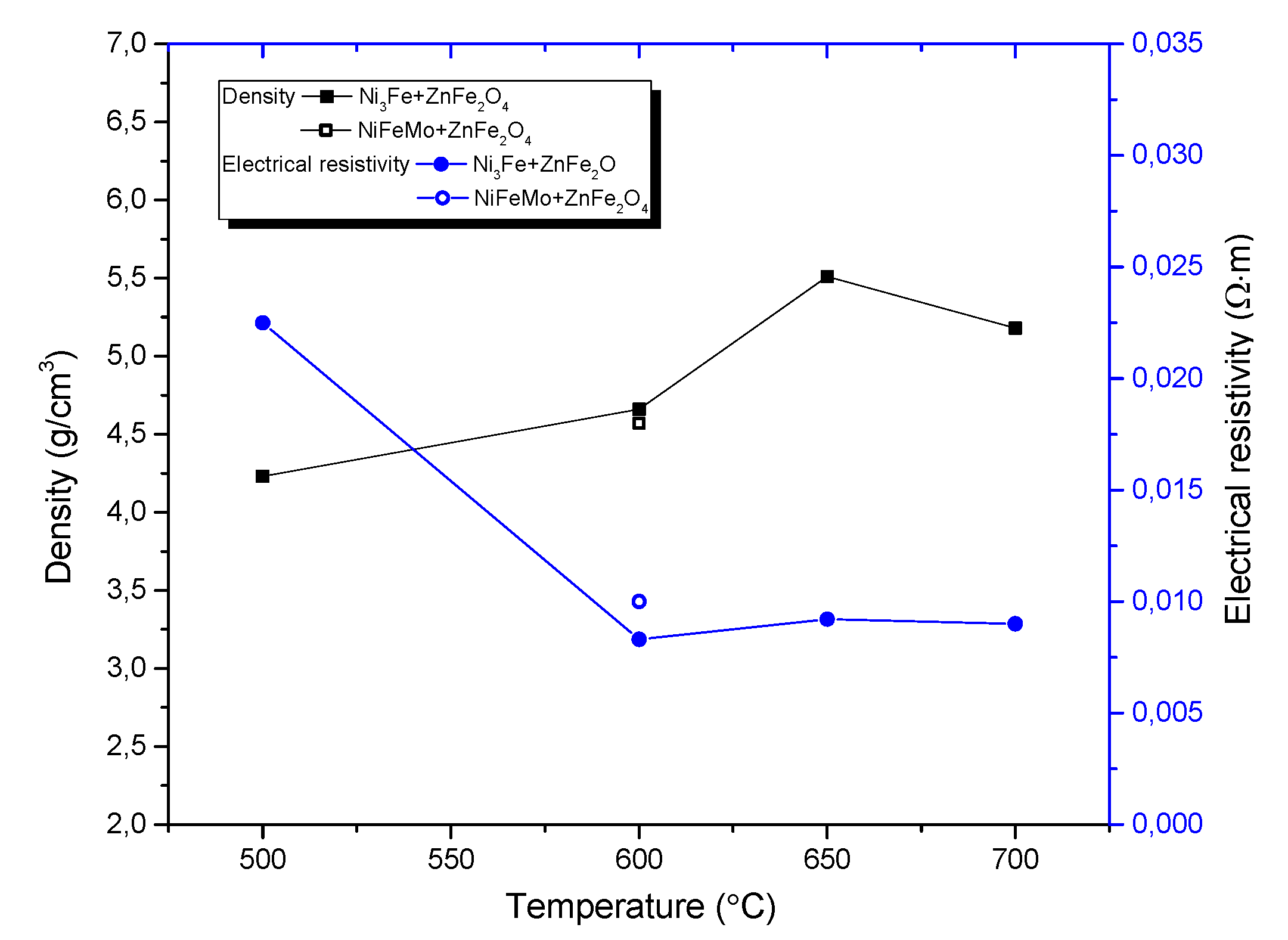
The influence of sintering temperature on the density and electrical resistivity of all composite compacts obtained by SPS from Ni
3Fe@ZnFe
2O
4 and Supermalloy@ZnFe
2O
4 pseudo-core-shell powders is shown in
Figure 6.
Figure 6 shows that the density of the composite increases with increasing sintering temperature. In the case of composite compacts obtained from pseudo-core-shell powders,
Figure 6, the electrical resistivity decreases strongly when the sintering temperature increases from 500 °C to 600 °C, after which it stabilises at values of about 7·10
-3 Ω·m for sintering temperatures between 600-700 °C, in correlation with the increasing density of the sintered compacts. This value is 3 orders of magnitude higher than the electrical resistivity of sintered Fe compacts (5.9·10
-6 Ω·m), which means that the energy losses in the core due to eddy currents are also 3 orders of magnitude lower than for magnetic Fe powder cores.
It is important to note that the electrical resistivity is highly dependent on many factors, such as: (i) the continuity of the ferrite network, (ii) the density of the sintered compacts, and (iii) the solid-state reaction between components during the sintering process, which can produce phases with different electrical resistivities.
The magnetic properties of the spark plasma sintered composite compacts produced from the Ni
3Fe@ZnFe
2O
4 and Supermalloy@ZnFe
2O
4 pseudo-core-shell powders were determined in DC and in AC up to 10,000 Hz. The B-H curves in DC of the Ni
3Fe/ZnFe
2O
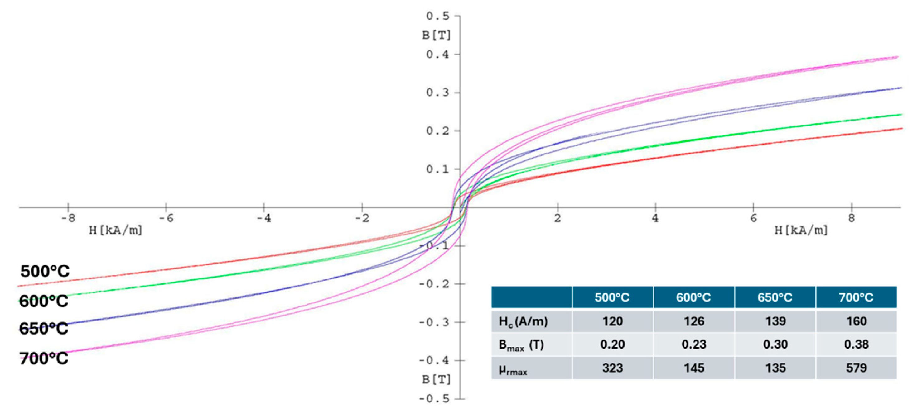
4 toroidal compacts obtained by SPS at different sintering temperatures are presented in
Figure 7. In the inset table of the figure, the coercive field, the magnetic induction, and the maximum relative permeability are detailed. It can be seen that the magnetic characteristics are better for the compacts obtained by sintering at 700 °C, excepting the coercive field. This is due to the formation of the new phases, ZnO and FeO, besides ZnFe
2O
4 and permalloy.
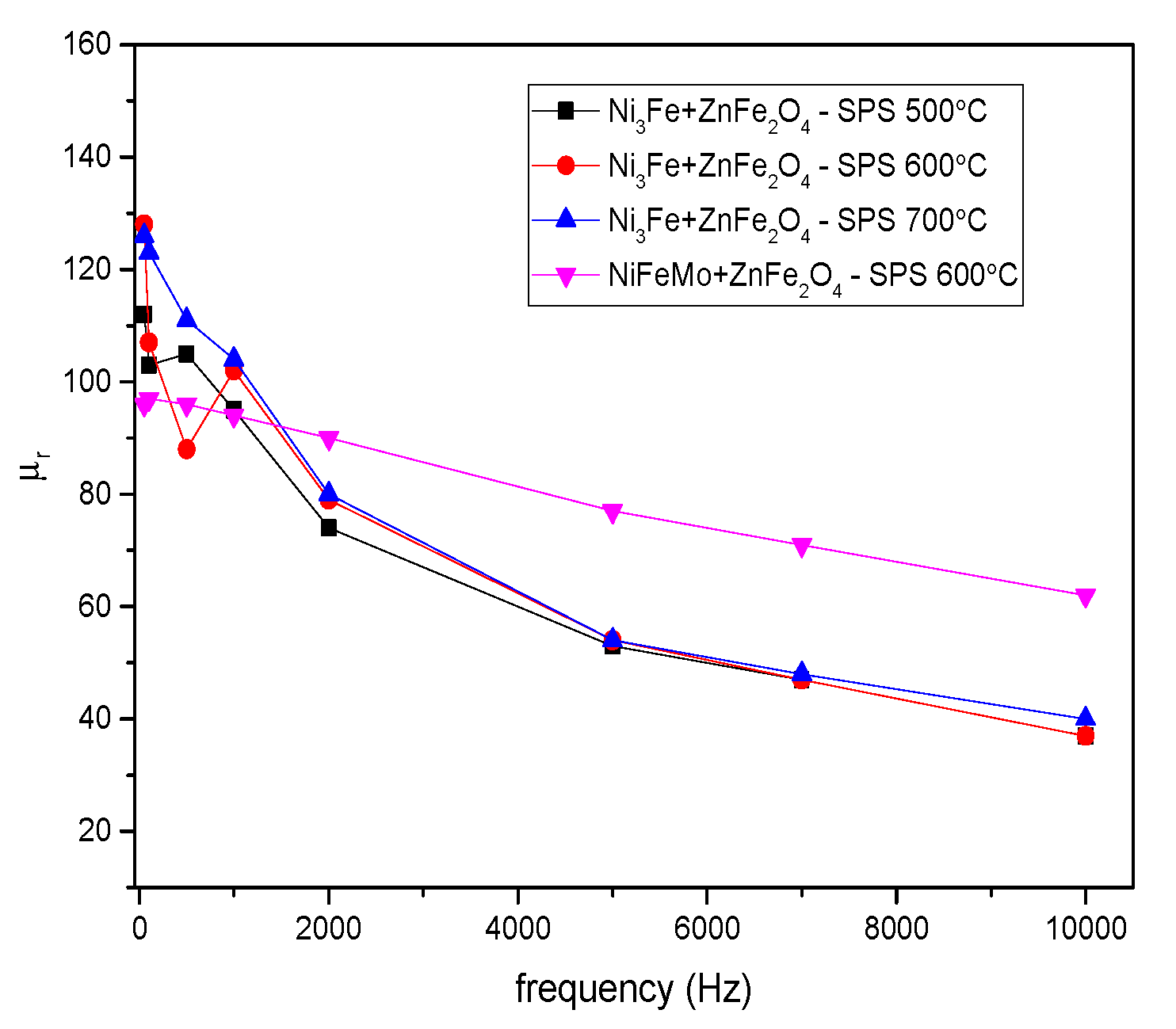
Figure 8 presents the evolution of initial magnetic permeability versus frequency for toroidal-shaped Ni
3Fe/ZnFe
2O
4 and NiFeMo/ZnFe
2O
4 composite compacts, SPS-ed at the sintering temperature indicated on the graph. The induction level was seated at 0.01 T.
As it is known, the magnetic permeability strongly depends on the porosity, density, and non-magnetic phases of the materials [
34,
35,
36]. A descending permeability evolution is noticed for all the compacts, evolution independent of the sintering temperature. The samples containing Ni
3Fe show a more rapid decrease independent of sintering temperature than those containing NiFeMo. A monotony decrease of the relative permeability versus frequency is observed for the NiFeMo/ZnFe
2O
4 compact sintered at 700 ºC. The higher relative initial permeability was obtained for the Supermalloy/ZnFe
2O
4 composite compacts sintered at 600 ºC, which decreases linearly for the entire frequency range studied, from around 95 to 50. The relative permeability values are larger than those of the SPS-ed compacts obtained by us from Permalloy (Supermalloy)@Mn
0.5Zn
0.5Fe
2O
4 pseudo-core-shell particles [
26]. The decrease is probably caused by the demagnetising field induced by the development of some eddy currents during increasing frequency. Due to the large electrical resistivity, it is assumed that some intra-particles eddy currents are developing since large particles have been used. The formation of some eddy currents is also suggested by the evolution of the losses upon increasing frequency.
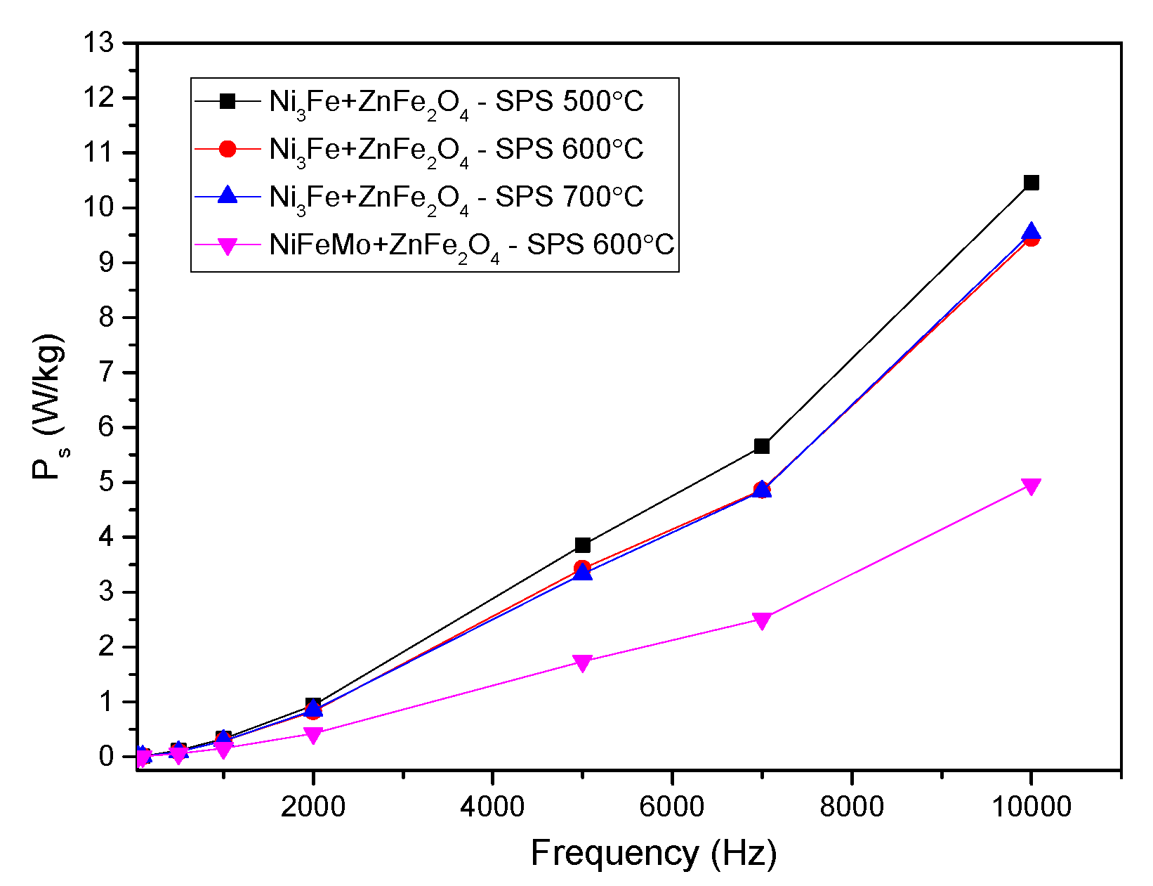
The evolution of the specific power losses versus the frequency for toroidal-shaped Ni
3Fe/ZnFe
2O
4 and NiFeMo/ZnFe
2O
4 type composite compacts, SPS-ed at the sintering temperature of 500 - 700 ºC at an induction level of 0.01 T, are shown in
Figure 9. A similar evolution of the specific power losses was obtained for all the compacts. Thus, the specific power losses increase exponentially with the increase in the testing frequency. The NiFeMo/ZnFe
2O
4 compact SPS-ed at 600 °C has the lowest losses. This can be related to the larger intrinsic electrical resitivity of the Supermaloy as compared to the one of Ni
3Fe.The results are promising; for the induction level of 0.01 T, until a frequency of 2,000 Hz, the power losses are lower than 1.5 W/kg. At the frequency of 10 kHz the power losses are larger, but still, they remain at a low level, lower than 15 W/Kg. In the case of Supermalloy/ZnFe
2O
4 composite compact SPS-ed at 600 °C, whitout holding time, the specific power losses are even lower than 5 W/kg. To certain attribution of the main part of the losses to the eddy current developed in the SPS-ed toroidal samples, mainly at intra-particles level a decomposition has been performed. The losses deconvolution has been done using the Bertotti classical loss separation model [
37,
38]. The total losses are composed of hysteresis losses and dynamic losses when the excess losses are not considered, as in our case. The dynamic losses are divided in two, inter-particles and intra-particles as it is well known.
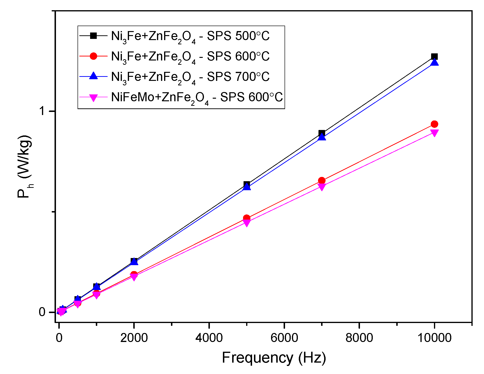
The evolution of the hysteresis losses versus frequency at 0.01 T are presented in
Figure 10. It can be noticed that the lower losses are given by the samples sintered at 600 ºC. This is related to the samples density and composite component phases. For this samples, the sintering temperature is limiting the formation of multiple phases at the interface.
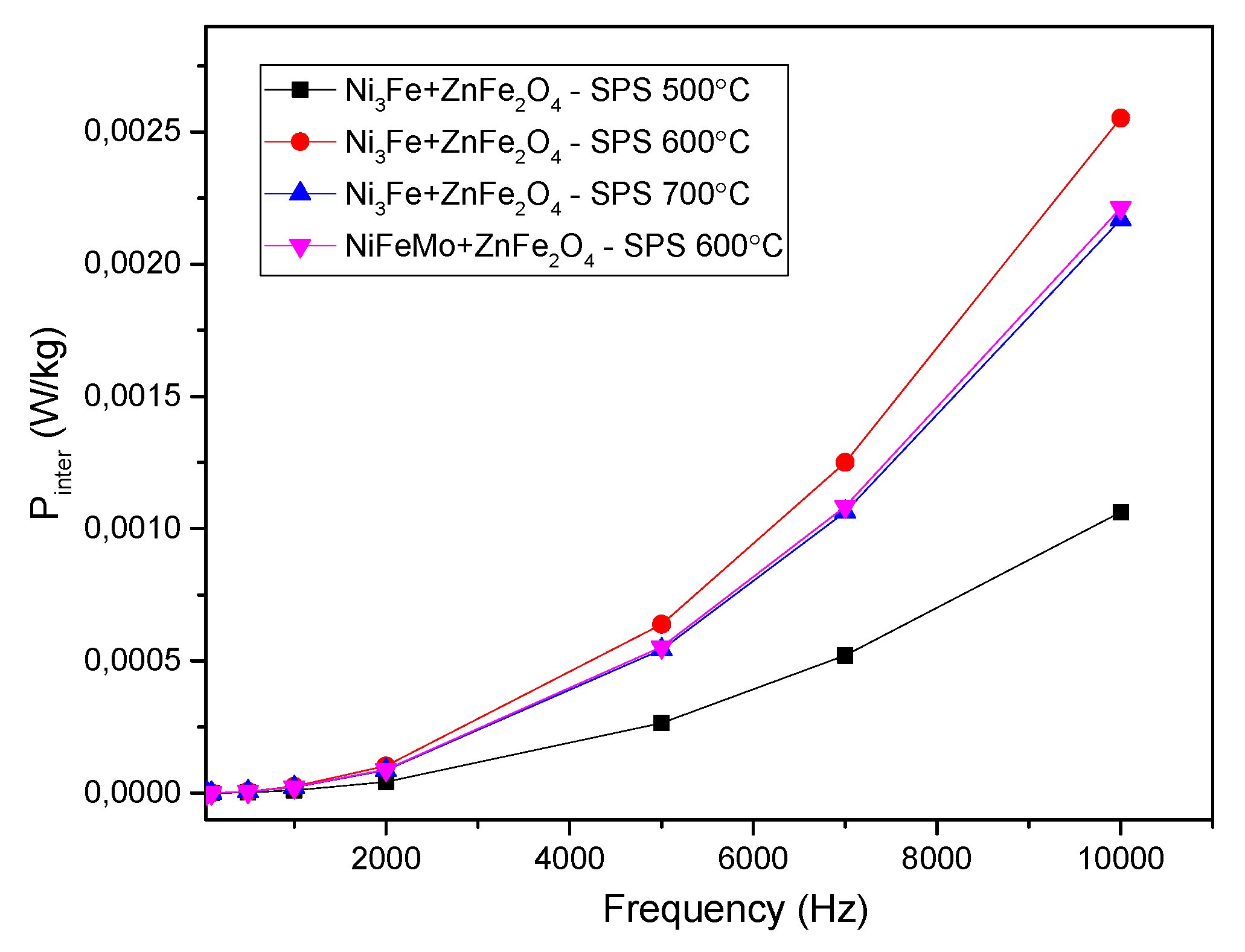
The inter-particles losses evolution is given in
Figure 11. A low value can be noticed for all the SMCs, which confirms the good insulation of the ferromagnetic particles in the sintered compacts. The evolution of the inter-particles losses is correlated with the sample’s density and electrical resistivity. The inter-particles losses are lower compared to the hysteresis losses.
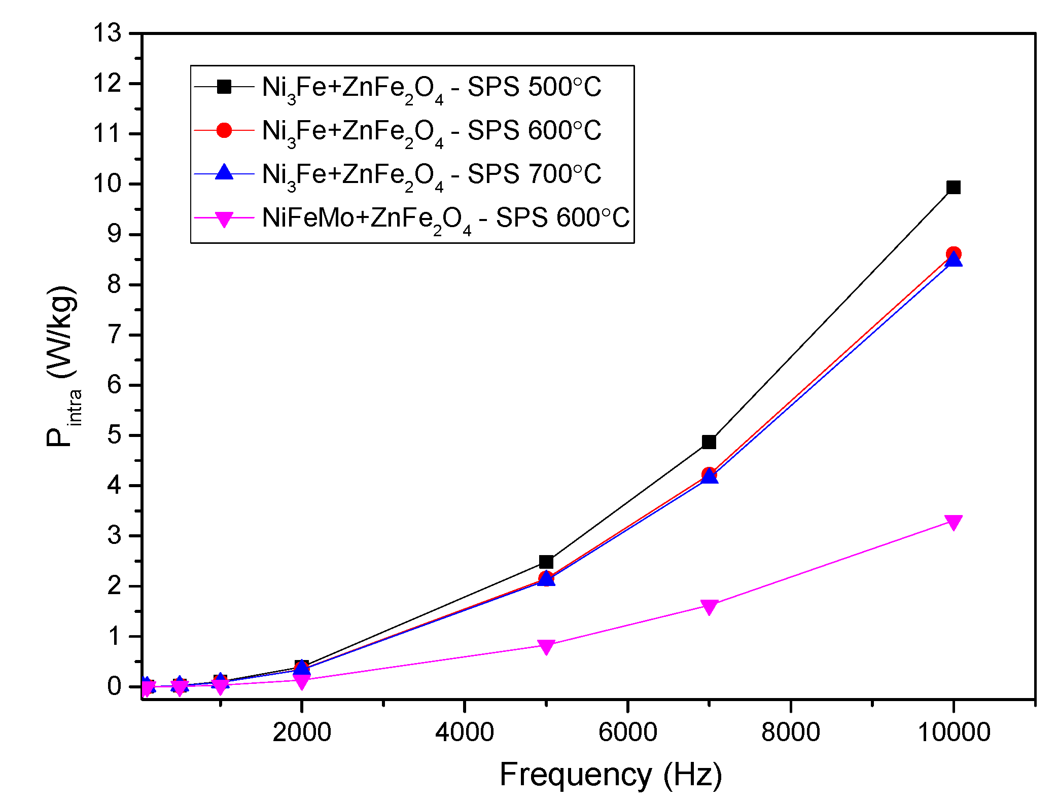
The intra-particles losses are depicted in
Figure 12. It can be observed that these losses represent the main part of the losses. The lower intra-particles losses are obtained for the samples containing NiFeMo. This is related to the higher intrinsic electrical resistivity of this alloy compared to Ni3Fe. The use of small particles is suggested and thus will lead to lower intra-particles losses. Also, it can be noticed that the formation of FeO and ZnO in a higher amount has a positive effect on diminishing the intra-particles losses. This is related to the reduction of effective particles size by the reaction on their surface of the iron (provided by Permalloy and Supermalloy) with zinc ferrite. The amount of FeO and ZnO are certainly at a relatively high amount, their maxima are easily visible in diffractograms, and the intensity increases upon increasing the sintering temperature.
5. Conclusions
Composite particles with pseudo-core-shell structure of Ni3Fe@ZnFe2O4 and NiFeMo/ZnFe2O4 types have been successfully produced from large ferromagnetic particles (Ni3Fe and NiFeMo) covered by a layer of fine Zn ferrite by mixing and homogenising for 15 minutes in a Turbula-type spatial homogeniser.
The pseudo-core shell structure of the powder has been highlighted by SEM and EDX studies. The composite powder has been subjected to spark plasma sintering in the temperature range of 500 to 700 °C. By this technique have been obtained soft magnetic composites with Ni-based particles embedded in an oxide matrix/network consisting mainly of ZnFe2O4 alongside the FeO and ZnO. ZnO and FeO are formed upon sintering by the reaction of iron atoms provided by Permalloy/Supermalloy and zinc ferrite at the interface of core-shell composite particles. The formation of the zinc and iron oxides has a positive effect on the powder densification and also on the compact’s electrical resistivity. The tests of the soft magnetic composite in the alternative field confirmed that the compacts have a structure that has a high electrical resistivity that limits/diminishes the development of eddy currents at an interparticle level. This was clearly demonstrated by the power losses separation, which indicated that the main part of the losses is given by intra-particles losses due to the use of large ferromagnetic particles. The use of ferromagnetic particles with lower sizes will ensure the decrease of the intra-particles losses.
Author Contributions
Conceptualisation, I.C.; methodology, I.C., T.F.M.; validation, I.C., T.F.M., F.P. and B.V.N.; formal analysis, I.C., T.F.M., F.P. and B.V.N.; investigation, L.C., T.F.M., F.P., B.V.N. and V.C.P.; resources, I.C.; writing—original draft preparation, L.C., T.F.M., I.C.; writing-review and editing, I.C., T.F.M., F.P., B.V.N. and V.C.P.; supervision, I.C.; project administration, I.C.; funding acquisition, I.C. All authors have read and agreed to the published version of the manuscript.
Funding
This work was supported by a grant from the Romanian Ministry of Education and Re-search, CCCDI—UEFISCDI, project number PN-III-P4-ID-PCE-2020-2264/PCE128/2021, within PNCD.
Institutional Review Board Statement
Not applicable.
Informed Consent Statement
Not applicable.
Data Availability Statement
The authors confirm that the data supporting the findings of this study are available within the article.
Conflicts of Interest
The authors declare no conflict of interest.
References
- Shokrollahi H.; Janghorban K. Soft magnetic composite materials (SMCs). J. Mater. Process. Technol. 2007, 189, 1–12.
- Silveyra, J.M.; Ferrara, E.; Huber, D.L.; Monson, T.C. Soft magnetic materials for a sustainable and electrified world. Science 2018, 362, 418. [CrossRef]
- Fan, X.; Wang, J.; Wu, Z.; Li, G. Core–shell structured FeSiAl/SiO2 particles and Fe3Si/Al2O3 soft magnetic composite cores with tunable insulating layer thicknesses. Mater. Sci. Eng. B 2015, 201, 79–86. [CrossRef]
- Périgo, E.A.; Weidenfeller, B.; Kollár, P.; Füzer, J. Past, present, and future of soft magnetic composites. Appl. Phys. Rev. 2018, 5, 031301-37. [CrossRef]
- Sunday, K.J.; Taheri, M. Soft magnetic composites: Recent advancements in the technology. Met. Powder Rep. 2017, 72, 425–429. [CrossRef]
- Streckova, M.; Szabo, J.; Batko, I.; Batkova, M.; Bircakova, Z.; Fuzer, J.; Kollar, P.; Kovalcikova, A.; Bures, R.; Medvecky, L. Design of Permalloy–ferrite–polymer soft magnetic composites doped by ferrite nanoparticles and visualisation of magnetic domains. Bull. Mater. Sci. 2020, 43, 37. [CrossRef]
- Calata, J.N.; Lu, G.Q.; Ngo, K. Soft Magnetic Alloy–Polymer Composite for High-Frequency Power Electronics Application. J. Electron. Mater. 2014, 43, 126–131. [CrossRef]
- Kordecki, A., Weglinski B. Powder Metall. 1990, 32 (1990) 151–155.
- Weglinski, B., in: J. Jenkins, J.V. Wood (Eds.), Selected Case Studies in Powder Metallurgy, The Institute of Metals, London, 1991, pp. 113–119.
- Kordecki A., Weglinski B., Dielectromagnetics Containing Different Dielectrics, Powder Metallurgy 1988, 31, 273–276. [CrossRef]
- Neamţu B.V., Geoffroy O., Chicinaş I., Isnard O. AC magnetic properties of the soft magnetic composites based on Supermalloy nanocrystalline powder prepared by mechanical alloying, Materials Science and Engineering: B 2012, 177, 661-665. [CrossRef]
- Hirota K., Kato M., Taguchi H., Fabrication of full-density Mg-ferrite/Fe-Ni permalloy nanocomposites with a hight-saturation magnetisation density of 1T, Int. J. Appl. Ceram.Technol. 2011, 8, 1-13.
- Moulin J., Champion Y., Varga L.K. Magnetic properties of nanocomposites containing Fe-Ni or Fe dispered in a Mn-Zn ferrite matrix, IEEE Trans Mag. 2002, 38, 3015-3017.
- Tarţa, V.F.; Marinca, T.F.; Chicinaş, I.; Popa, F.; Neamţu, B.V.; Pascuta, P.; Takacs, A.F. Stability of Phases in Ball-Milled Zinc Ferrite/Iron Composite Produced by Spark Plasma Sintering. Mater. Manuf. Process. 2013, 28, 933-938. [CrossRef]
- Fang M., StromV., Olsson R.T., Rao K.V. Particle size and magnetic properties dependence on grow temperature for srapid mixed co-precipitated magnetite nanoparticles, Nanotechnology 2012, 23, 145601.
- Wilson D., Langell M.A. XPS analysis of oleylamine/oleic acid capped Fe3O4 nanoparticles as a function of temperature, Appl. Surf.Sci. 2014, 303, 6-13.
- Kalarus J., Kogias G., Holz D., Zaspalis V.T. High permeability–high frequency stable MnZn ferrites. J. Magn. Magn. Mater. 2012, 324, 2788–2794.
- Akther Hossain A.K.M., Mahmud S.T., Seki M., Kawaib T., Tabata H. Structural, electrical transport, and magnetic properties of Ni1−xZnxFe2O4. J. Magn. Magn. Mater. 2007, 312, 210–219.
- Marinca, T.F.; Neamţu, B.V.; Popa, F.; Tarţa, V.F.; Pascuta, P.; Takacs, A.F.; Chicinaş, I. Synthesis and characterisation of the NiFe2O4/Ni3Fe nanocomposite powder and compacts obtained by mechanical milling and spark plasma sintering. Appl. Surf. Sci. 2013, 285P, 2–9. [CrossRef]
- Wang, L.; Zhang, J.; Jiang, W.; Recent development in reactive synthesis of nanostructured bulk materials by spark plasma sintering. Int. J. Refract. Met. Hard Mater. 2013, 39, 103–112,. [CrossRef]
- Wang, M.; Zan, Z.; Deng, N.; Zhao, Z. Preparation of pure iron/Ni–Zn ferrite high strength soft magnetic composite by spark plasma sintering. J. Magn. Magn. Mater. 2014, 361, 166-169. [CrossRef]
- Marinca, T.F.; Chicinaş, H.F.; Neamţu, B.V.; Popa, F.; Chicinaş, I. Reactive spark plasma sintering of mechanically activated α-Fe2O3/Fe. Ceram. Int. 2017, 43, 4281–14291. [CrossRef]
- Hu, Z.Y.; Zhang, Z.H.; Cheng, X.W.; Wang, F.C.; Zhang, Y.F.; Li, S.L. A review of multi-physical fields induced phenomena and effects in spark plasma sintering: Fundamentals and applications. Mater. Des. 2020, 191, 108662. [CrossRef]
- Marinca T.F., Popa F., Neamțu B.V., Prică C.V., Chicinaș I. Permalloy/alumina soft magnetic composite compacts obtained by reaction of Al-permalloy with Fe2O3 nanoparticles upon spark plasma sintering, Ceramics International. 2023, 49, 2272-2281. [CrossRef]
- Marinca T.F., Cotojman L, Neamțu B.V., Popa F., Prică C.V., Hirian R., Sechel N.A., Ciascai I., Chicinaș I., Soft magnetic composite of Ni3Fe/ZnFe2O4 type obtained by mechanical alloying/milling and spark plasma sintering, Ceramics Int. 2024, 50 7547–7557. [CrossRef]
- Cotojman L., Marinca T.F., Popa F., Neamțu B.V., Prică V.C., Chicinaș I. Producing Soft Magnetic Composites by Spark Plasma Sintering of Pseudo Core–Shell Ni–Fe Alloy@Mn0.5Zn0.5Fe2O4 Powders, Materials 2023, 16, 501. [CrossRef]
- Chicinaș I.¸ Pop V., Isnard O., Le Breton J.M., Juraszek J., Synthesis and magnetic properties of Ni3Fe intermetallic compound obtained by mechanical alloying, J. Alloys Compd. 2003, 352, 34–40. [CrossRef]
- Chicinaș I.¸ Pop V., Isnard O., Synthesis of the Supermalloy powders by mechanical alloying, J. Mater. Sci. 2004, 39, 5305-5309.
- https://doi.org/10.1023/B:JMSC.0000039234.58490.78. [CrossRef]
- Spârchez Z., Chicinaș I., Isnard O., Pop V., Popa F., Mechanical alloying of Ni3Fe in the presence of Ni3Fe nanocrystalline germs, J. Alloys Compd. 2007, 434–435, 485–488,. [CrossRef]
- Popa F., Isnard O., Chicinaș I., Pop V., Synthesis of nanocrystalline Supermalloy powders by mechanical alloying: A thermomagnetic analysis. J. Magn. Magn. Mater. 2010, 322, 1548-1551. [CrossRef]
- Neamţu B.V., Chicinaş I., Isnard O., Popa F., Pop V., Influence of wet milling conditions on the structural and magnetic properties of Ni3Fe nanocrystalline intermetallic compound. Intermetallics 2011 19, 19-25. [CrossRef]
- Popa F., Isnard O., Chicinas I., Pop V., Thermal evolution of the Ni3Fe compound obtained by mechanical alloying as probed by differential scanning calorimetry, J. Alloys Compd. 2013, 554, 39–44. [CrossRef]
- Le Breton J.M., Isnard O., Jurassic J., Pop V., Chicinaș I.¸ A Mössbauer investigation of the formation of the Ni3Fe phase by high energy ball milling and subsequent annealing, Intermetallics 2013, 35, 128-134,. [CrossRef]
- Onderko, F.; Birčáková, Z.; Dobák, S.; Kollár, P.; Tkáč, M.; Fáberová, M.; Füzer, J.; Bureš, R.; Szabó, J. Magnetic properties of soft magnetic Fe@SiO2/ferrite composites prepared by wet/dry method. J. Magn. Magn. Mater. 2022, 543, 168640.
- Bozorth, R.M. Ferromagnetism, 3rd edition, Piscataway, New Jersey, IEEE Press, 1993.
- Cullity, B.D.; Graham, C.D. Introduction to Magnetic Materials, second ed., IEEE Press&Wiley, New Jersey, USA, 2009.
- Bertotti G. General properties of power losses in soft ferromagnetic materials. IEEE Transaction on Magnetics 1988, 24, 621-630.
- Kollár P., Olekšáková D., Vojtek V., Füzer J., Fáberová M., Bureš R. Steinmetz law for acmagnetised iron-phenolformaldehyde resin soft magnetic composites, J. Magn. Magn. Mater. 2017, 424, 245-250.
Figure 1.
Morphology of powders homogenised for 20 minutes: (a) Ni3Fe@ZnFe2O4 and (b) 79Ni16Fe5Mo@ZnFe2O4.
Figure 1.
Morphology of powders homogenised for 20 minutes: (a) Ni3Fe@ZnFe2O4 and (b) 79Ni16Fe5Mo@ZnFe2O4.
Figure 2.
X-ray diffraction patterns for the SPS-ed composite compacts obtained from Ni3Fe@ZnFe2O4 and Supermalloy@ZnFe2O4 pseudo-core-shell powders as a function of sintering parameters.
Figure 2.
X-ray diffraction patterns for the SPS-ed composite compacts obtained from Ni3Fe@ZnFe2O4 and Supermalloy@ZnFe2O4 pseudo-core-shell powders as a function of sintering parameters.
Figure 3.
The surface of SPS-ed composite compacts, obtained from Ni3Fe@ZnFe2O4 pseudo-core-shell powders. The sintering temperature is shown on top of the SEM images.
Figure 3.
The surface of SPS-ed composite compacts, obtained from Ni3Fe@ZnFe2O4 pseudo-core-shell powders. The sintering temperature is shown on top of the SEM images.
Figure 4.
SEM images of SPS-ed and superimposed distribution maps for Ni, Fe, O and Zn elements in the SPS composite compacts obtained at 500, 600 and 700 °C from Ni3Fe@ZnFe2O4 pseudo-core-shell particles.
Figure 4.
SEM images of SPS-ed and superimposed distribution maps for Ni, Fe, O and Zn elements in the SPS composite compacts obtained at 500, 600 and 700 °C from Ni3Fe@ZnFe2O4 pseudo-core-shell particles.
Figure 5.
SEM images and distribution maps for Ni, Fe, O and Zn elements in the SPS-ed composite compacts obtained at 700 °C temperature from Supermalloye@ZnFe
2O
4 pseudo-core-shell particles: a. – SEM image; b. – elemental distribution maps superimposed on the SEM image from
Figure 6a; c-g – distribution maps for Ni, Fe, O and Zn elements, respectively. .
Figure 6.
Density and electrical resistivity of plasma sintered Ni3Fe/ZnFe2O4 composite compacts versus temperature.
Figure 6.
Density and electrical resistivity of plasma sintered Ni3Fe/ZnFe2O4 composite compacts versus temperature.
Figure 7.
The B–H hysteresis curves in DC of the Ni3Fe/ZnFe2O4 composite compacts, SPS-ed at temperatures: 500 , 600, 650 and 700 ºC. Holding time was 0 minutes.
Figure 7.
The B–H hysteresis curves in DC of the Ni3Fe/ZnFe2O4 composite compacts, SPS-ed at temperatures: 500 , 600, 650 and 700 ºC. Holding time was 0 minutes.
Figure 8.
Evolution of initial magnetic permeability versus frequency for toroidal shaped Ni3Fe/ZnFe2O4 and NiFeMo/ZnFe2O4 composite compacts, SPS-ed at the sintering temperature indicated on the graph. The induction level was seated at 0.01 T.
Figure 8.
Evolution of initial magnetic permeability versus frequency for toroidal shaped Ni3Fe/ZnFe2O4 and NiFeMo/ZnFe2O4 composite compacts, SPS-ed at the sintering temperature indicated on the graph. The induction level was seated at 0.01 T.
Figure 9.
Evolution of the specific power losses versus frequency for toroidal shaped Ni3Fe/ZnFe2O4 and NiFeMo/ZnFe2O4 composite compacts, SPS-ed at the sintering temperature indicated on the graph. The induction level was seated at 0.01 T.
Figure 9.
Evolution of the specific power losses versus frequency for toroidal shaped Ni3Fe/ZnFe2O4 and NiFeMo/ZnFe2O4 composite compacts, SPS-ed at the sintering temperature indicated on the graph. The induction level was seated at 0.01 T.
Figure 10.
Evolution of the hysteresis losses versus frequency for toroidal shaped Ni3Fe/ZnFe2O4 and NiFeMo/ZnFe2O4 composite compacts, SPS-ed at the sintering temperature indicated on the graph. The induction level was seated at 0.01 T.
Figure 10.
Evolution of the hysteresis losses versus frequency for toroidal shaped Ni3Fe/ZnFe2O4 and NiFeMo/ZnFe2O4 composite compacts, SPS-ed at the sintering temperature indicated on the graph. The induction level was seated at 0.01 T.
Figure 11.
Evolution of the inter-particles losses versus frequency for toroidal shaped Ni3Fe/ZnFe2O4 and NiFeMo/ZnFe2O4 composite compacts, SPS-ed at the sintering temperature indicated on the graph. The induction level was seated at 0.01 T.
Figure 11.
Evolution of the inter-particles losses versus frequency for toroidal shaped Ni3Fe/ZnFe2O4 and NiFeMo/ZnFe2O4 composite compacts, SPS-ed at the sintering temperature indicated on the graph. The induction level was seated at 0.01 T.
Figure 12.
Evolution of the intra-particles losses versus frequency for toroidal shaped Ni3Fe/ZnFe2O4 and NiFeMo/ZnFe2O4 composite compacts, SPS-ed at the sintering temperature indicated on the graph. The induction level was seated at 0.01 T.
Figure 12.
Evolution of the intra-particles losses versus frequency for toroidal shaped Ni3Fe/ZnFe2O4 and NiFeMo/ZnFe2O4 composite compacts, SPS-ed at the sintering temperature indicated on the graph. The induction level was seated at 0.01 T.
|
Disclaimer/Publisher’s Note: The statements, opinions and data contained in all publications are solely those of the individual author(s) and contributor(s) and not of MDPI and/or the editor(s). MDPI and/or the editor(s) disclaim responsibility for any injury to people or property resulting from any ideas, methods, instructions or products referred to in the content. |
© 2024 by the authors. Licensee MDPI, Basel, Switzerland. This article is an open access article distributed under the terms and conditions of the Creative Commons Attribution (CC BY) license (http://creativecommons.org/licenses/by/4.0/).
