Preprint
Article
Development of a Multi-Motor Asynchronous Electric Drive with Changes in the Coordinated Rotation of the Supply Voltages of the Motors
Altmetrics
Downloads
90
Views
31
Comments
0
A peer-reviewed article of this preprint also exists.
Submitted:
15 July 2024
Posted:
16 July 2024
You are already at the latest version
Alerts
Abstract
In the proposed article, the issues of increasing the synchronizing ability of the system of coordinated rotation of asynchronous motors are considered. Based on the T-shaped equivalent circuit, electromechanical relationships were obtained with changes in the value of the total rotor resistance and the supply voltage of individual motors. An algorithm for calculating the torques, stator and rotor currents of the motors of the system has been compiled. Based on the calculations obtained, the mechanical characteristics of the system asynchronous motors are constructed for various values of total resistance, supply voltages and rotor positions. The obtained data and graphs confirm the adequacy of the theory obtained in an analytical way. Functional and structural diagrams in small scales have been compiled, which allow simulating transient operation modes of multi-motor asynchronous electric drives in the Matlab application package. Multi-motor asynchronous electric drives with adjustable supply voltages, as well as with preliminary synchronization and synchronous braking, have been developed. Compilation of a program for the stability of a nonlinear system of a multi-motor asynchronous electric drive (MAEDs) with a thyristor voltage converter (TVC) in Matlab. Also, the modes of soft start, load shedding and surge on the motor shaft are simulated, confirming the stability of the system.
Keywords:
Subject: Engineering - Electrical and Electronic Engineering
1. Introduction
In a number of production mechanisms, machines and units of various industries, the synchronous rotation of several motors, interconnected mechanically, electrically or technologically, is required. Such mechanisms include carding machines, belt and chain conveyors, unified building vibration platforms, cold rolling mills, paper machines, etc. In most drives of technological processes, the drive motors are not kinematically rigidly connected to each other. Synchronization of rotation of asynchronous motors of these mechanisms is achieved through the use of a relay-contact or control system for motors connected electrically and according to the classical “electric shaft” scheme. Systems of the “energy shaft”, in turn, are divided into an electric operating shaft (EOS), an electric equalizing shaft (EES). Their distinctive features are discussed in detail in the monograph. Such systems have significant disadvantages: low synchronizing capacity, tendency to self-oscillations, as a result - a narrow stability region, large losses of electrical energy in common rotor circuits, etc. The modern development of elements of power electronics, converter and microprocessor technology allows, on the basis of cheap, reliable asynchronous electric motors, to create a wide variety of control systems for multi-motor asynchronous electric drives and expand the possibilities of their synchronous rotation even with significant differences in load torques. Thus, the creation and widespread implementation of control systems for multi-motor asynchronous electric drives of synchronous, synchronous-in-phase rotation, which make it possible to improve the quality of output products and the productivity of technological processes, is an urgent task. The development and optimization of multi-motor asynchronous electric drives (MAEDs) represent a pivotal area in modern electromechanical engineering. These systems play a crucial role in various industrial applications where precise synchronization and efficient operation are paramount. This study focuses on advancing the understanding and capabilities of MAEDs through the development of a method for calculating mechanical characteristics and exploring their behavior under variable supply voltages. Asynchronous motors, with their robustness and adaptability, are widely employed in industrial settings due to their ability to handle diverse loads and operational conditions. However, achieving optimal synchronization among multiple motors, especially when subjected to fluctuations in supply voltages, remains a challenging yet essential objective. This article addresses this challenge by proposing a systematic approach to analyze and optimize the performance of MAEDs under varying electrical inputs. The methodology leverages a T-shaped equivalent circuit to derive essential parameters such as torque, stator, and rotor currents, while considering angular deviations and electrical phase shifts. Practical validation and simulation in Matlab provide insights into transient behaviors and stability under different operational scenarios, thereby offering a comprehensive understanding of the system’s dynamic response. By examining the impact of supply voltage variations on mechanical characteristics and synchronization efficiency, this study aims to contribute valuable insights into enhancing the reliability, efficiency, and adaptability of MAEDs in industrial applications. The results and discussions presented herein underscore the importance of tailored control strategies and optimal voltage management for achieving seamless operation and maximizing energy efficiency in multi-motor asynchronous electric drives.
2. Materials and Methods
The main electromechanical ratios of the EOS three-engine system are found from the T-shaped equivalent circuit. The angular mismatches of the rotors of differently loaded motors are denoted by φ1, φ2, φ3 relative to some imaginary axis rotating in coordination with the motor rotors. According to the theory of the electric shaft, mechanical angles of rotation can be taken into account in electrical degrees relative to the applied voltages along the stator circuits, i.e., by multiplying the voltages by . Phase shifts of all motor currents are taken into account by multiplying by the same multipliers. This approach is necessary to make the formulas more symmetrical. Further calculations are carried out according to the principle of the overlay method.
For an analytical study of multi-motor electric drives with electrical communication through rotary circuits, when the supply voltage of individual motors changes, we accept the following generally accepted assumptions in the electric drive:
- -
- the parameters of the system engines are identical;
- -
- the magnetic field along the circumference of the air gap of each engine is distributed evenly, only the main harmonic field is taken into account;
- -
- losses in the steel of the stator and rotor are not taken into account, the magnetic circuits of the motors are unsaturated;
- -
- voltage applied to the stator windings, symmetrical three-phase;
- -
- superposition principle is used to determine currents and torques;
- -
- the resistance of the connecting cables is not taken into account;
- -
- in the study of stability, deviations “in the small” are taken into account.
To determine the currents and moments of the MAEDs synchronous rotation (SR) system with electrical communication through common rotor circuits, which includes three asynchronous motors, we use its T-shaped equivalent circuit, which is shown in Figure 1, where respectively marked (see Figure 1):
U1, U2, U3 – is the mains voltages for each motor;
I11, I12, I13, I21, I22, I23 – is the stator and rotor currents of the machines, respectively;
r11, r12, r13 and х11, х12, х13 – is the active and inductive resistances of the stator windings of the corresponding motors of the system with electrical connection through rotor circuits;
r21, r22, r23 and х21, х22, х23 – is the active and inductive resistances of the rotor windings;
х01, х02, х03 – is the inductive resistances of the magnetization circuits;
Ra - is the additional resistance in the rotor circuit;
S - is the slip;
φ1, φ2, φ3 – is the angular shifts of the rotors in electrical degrees relative to the accepted reference axis.
Denoting the complex resistances of the stators and rotors during sliding S through Z1, Z2, taking into account the identity of the motor parameters and reduction of rotor resistances, we obtain:
where , - is the active and inductive resistance of the rotors, respectively, reduced to the stator.
Then the voltage equations for the stator and rotor circuits are:
In our case, the parameters of all three motors are strictly identical (Р1n= Р2n= Р3n, n1n = n2n= n3n, I11n= I12n= I13n= I21n= I22n= I23n) and the voltage equation systems will take the form:
Having determined the values of the stator currents from Eq. (5) substituting into the system of Eq. (6). After transformation we get:
Summing up these equalities:
Determine the current in the common rotor circuit:
Substituting the values of the total currents of the currents into the system of Eq. (7) we obtain:
From the 10th equation we find the rotor currents:
Stator currents are defined as:
For the 2nd, 3rd engine are equal:
Neglecting the active resistance and designating Z, x through , , where is the primary dissipation factor, the rotor currents are defined as:
Developed engine moments:
where , , are complex quantities.
We represent the current as:
given that , , .
We determine the developed moments of the engines:
Changes in the supply voltage of the motors were indicated by the coefficients:
; ; .
Further, taking into account the previously accepted assumptions, and introducing the coefficients of voltage change , , , we will find the equations for the currents and moments of the motors in the system, taking into account the identity of the parameters of the motors included in the system. Assuming that and , we write the stator and rotor voltage equations for each motor of a three-motor system of synchronous rotation with electrical connection through rotor circuits in the form:
Taking into account the possible changes in voltages , , using the coefficients , , and substituting the value of the stator currents from Eq. (18) into Eq. (19), we obtain the expressions for rotor currents Eq. (20). Since the engines of the coordinated rotation system are assumed to be identical, we will write the expressions for rotor currents and moments only for the first engine:
where , , . respectively, are the maximum moments of the engines.
We write expressions for the moment of the first engine, dividing them into asynchronous and synchronizing components:
As can be seen from equation (22), the magnitude of the torque and, accordingly, the equalizing torque of a given motor are interrelated affected by changes in the supply voltages of other machines. Similarly, one can write an expression for currents, moments, and synchronizing moments of a multi-motor system with adjustable voltage, from which, as a special case, currents, moments for two, three, etc. can be found. motor controlled and unregulated system of synchronous rotation with electrical connection through rotary circuits. Turquoises for a synchronous rotation system with electrical connection through rotary circuits with the nth motor are defined as:
where the first term is the asynchronous component, the second is the synchronizing component. The general equalizing moment in the n motor system of synchronous rotation between the nth and mth motor has the expression:
To calculate the mechanical characteristics, we use Eq. (8), while giving different values to the mismatch angles, changing the magnitude of the supply voltage, and also changing the total rotor resistance. According to the above expressions, a calculation was carried out for motors of the type Ue, 56a, 154W, IP44 of the electric drive carding machine (CM) CR-24 with the following parameters:
W; W; rpm; A; A; Hz.
3. Algorithm for Calculating the Electromechanical Ratio of a Multi-Motor Asynchronous Electric Drive
The algorithm for calculating the mechanical characteristics of the three-engine MAEDs system, taking into account the change and the angular positions of the rotor, is shown in Figure 2, and the mechanical characteristics are plotted when changing various parameters. By changing the values of these coefficients and angles, you can obtain a large number of graphs of mechanical characteristics shown in Figure 2.
The results of the calculation are shown in Figure 3. The calculated curves of mechanical characteristics are built for three values of additional resistances corresponding to three stages and critical slips:; 0,347; 0,645 (see Figure 3a) and mismatch angles (see Figure 3b), , (see Figure 3c) of the engine rotors.
The curves with slip , shown in Figure 3a, are typical for the operating CM of the CR-24 type, the value of the resistance not switched off from the common rotor circuit is taken equal to 0.19 Ω from the point of view of the parameters that are optimal according to technological requirements. At the same time, the rigidity of the mechanical characteristic is much lower than that of the characteristics with (dashed line with a dot) and (dashed line) in Figure 3a. At , the EOS system tends to self-oscillate at static moments higher than . The system at critical angles of mismatch develops an equalizing maximum moment equal to , i.e., it can work stably at values of static moments that satisfy the condition: . Figure 3b shows the dependences of for several slip values in the presence of resistance ; 0.08; 0.19Ω. Obviously, approaching the synchronous speed greatly reduces the magnitude of the synchronizing components of the motor torques. An increase in the value of active resistances in the common rotor circuit simultaneously with a decrease in the speed of the entire system increases its synchronizing capacity. The negative values of the synchronizing components of the moments are due to the difference in the loads on the shafts. In this case, the synchronizing torques maintains consistent rotation. The difference between these moments determines the action of the entire system. For example, in the variant under consideration, the first engine is assumed to be the most loaded, and its synchronizing component of the torque is equalized by the sum of the moments of the other two engines, i.e., . Figure 3a shows the synchronizing torques of the system engines at mismatch angles of the position of the rotors canst. Equalizing moments between the first and third, second and third engines of the system at angle take maximum values, gradually decreasing with increasing . The synchronizing component of the torque of the third machine at is equal to zero, and the other machines are equal to each other, but have opposite signs. Equalizing moments reach their maximum at , equal to zero at and (see Figure 3b). With small slips, the motors of the system develop only very limited moments; therefore, their synchronizing components are small. Therefore, we can conclude that the EOS system in the CM drive works satisfactorily with a slip of at least 0.15-0.3 (see Figure 3c and Figure 3d). The above calculations have shown that in systems with large additional resistances, the torques of certain motors become negative, i.e., the system can only work when mechanical energy is supplied to these motors from the load side. As can be seen from expression Eq. (26), the total equalizing moment between the motors consists of the sum of the asynchronous and synchronizing components of the motors. Equalizing moments are also formed due to the difference in drive torques. Graphs based on the calculation results when the supply voltage of the motors changes is shown in Figure 4.
In a MAEDs system with TVC, the synchronizing capacity of the system is determined by equalizing torques consisting of the difference in the torques of the motors of the system with changes in the magnitude of the supply voltage. The mechanical characteristics of the system engines (in Figure 4a) were obtained with U1=U2=U3 and φ1=φ2=φ3=0 i.e., all characteristics are identical from the accepted condition of the identity of engines М1, М2, М3. All characteristics are obtained with the minimum residual resistance in the common circuit of the rotors. In the characteristics (b, c, d), the supply voltages are changed within 75% -90% of the nominal value, and the angular positions of individual rotors are in the range from 0° дo 90°. In Figure 4 (e, c), the mechanical characteristics are similar, but differ at the same total voltages for the first and third engines, and the value of the second engine is reduced by 25% and differ in the angular positions of the rotors (20° and 45°). The results of the study reveal that the difference in angular positions does not exceed 45° и 70°, and the value of the supply voltage is from 0.75 to 1.0 of the nominal value. With such AM with TVC changes, the system works stably. Equalizing moments are also formed due to the difference in drive moments. From the obtained expressions of the moments it follows that with the in-phase rotation of three machines, that is, with and :
In this case, all three machines operate on rheostatic characteristics with tripled additional resistance 3Ra, and the equalizing moments are equal to zero.
4. Development of an Adjustable Multi-Motor Asynchronous Electric Drive
Many variants of a multi-motor asynchronous electric drive (MAEDs) with thyristor voltage converters (TVC) have been proposed, showing a significant improvement in the synchronizing capacity of such systems compared to the classical system of asynchronous electric drive of matched rotation [7,8,9]. One of the areas of such developments is multi-motor asynchronous electric drives with adjustable supply voltages [4]. The principle of this system is to increase the synchronizing capacity of MAEDs by regulating the supply voltages according to the load of the motors, i.e., the maximum loaded motor is supplied with maximum energy, and the less loaded motor is supplied with voltage according to the load. Figure 5 shows MAEDs with TVC, made on thyristors (a) [11] and on transistors (b) [12]. MAEDs with TVC works like this:
In practical implementation, the power circuit of the TVC-AM system contains six thyristors connected in pairs in anti-parallel to the stator circuits of a three-phase asynchronous motor [13,14,15]. Such a converter is designed to regulate the 1st, or fundamental, harmonic that feeds the voltage motor by changing the thyristor opening angle α in the range from α=φ to α=1800. In this case, the effective phase voltage of the first harmonic changes from U1=U1nom (where U1=U1nom is the effective phase rated voltage of the supply network; φ is the phase angle of the load, determined from the design parameters of the motors to U1=0).
The frequency of the alternating voltage of the fundamental harmonic remains unchanged and is equal to the mains frequency, i.e., f1= f1nom With this control, the synchronous speed of the asynchronous motor and the critical slip do not change, but the motor torque is controlled. The degree of loading of the motors is determined: in the sensors of the phase of the rotor currents, signals are selected that are proportional to the phases of the rotor currents and converted into a control signal proportional to the angles of mismatch of the rotor currents of each motor relative to the total rotor current. Therefore, a signal equal to:
The control signals Uy1, Uy2, Uy3 contribute, by changing the energy flow supplied to each motor, to equalize the phases of the rotor currents, that is, the synchronism of the rotation of the speeds of all the motors of the MAEDs system with TVC. The equalizing moment of the system with a common rotor resistance is subject to a synchronizing effect caused by the difference in the voltages supplying the motors. In this case, the leading motor, which has a lower load, is supplied with less voltage, and the lagging one is supplied with more voltage in accordance with the magnitude and sign of the mismatch angle. The thyristor groups of the most loaded motor open completely.
Here, the mismatch angles are determined by the load difference, therefore, the control accuracy of a multi-motor asynchronous electric drive of synchronous rotation is determined by the accuracy and measurement limits of the mismatch angle of the position of the rotors, due to the difference in load moments on the shafts of electric motors that are not kinematically connected to each other.
The rest of the engines receive power in accordance with the load. The general speed control of the MAEDs system with TVC in accordance with the technological requirements in small ranges can be made by changing the signal U3 or the total resistance Ra, which in this scheme can be minimal. A multi-motor asynchronous electric drive has been developed that allows for synchronous torque control using asymmetric voltage regulators and synchronous braking by asymmetric power supply of stator windings of asynchronous electric motors. This circuit solution provides preliminary synchronization of the rotors of all motors by closing back-to-back thyristors in one phase, as well as synchronous braking of motors or operating mechanisms after turning on the thyristors and connecting the windings of the third phase to the second.
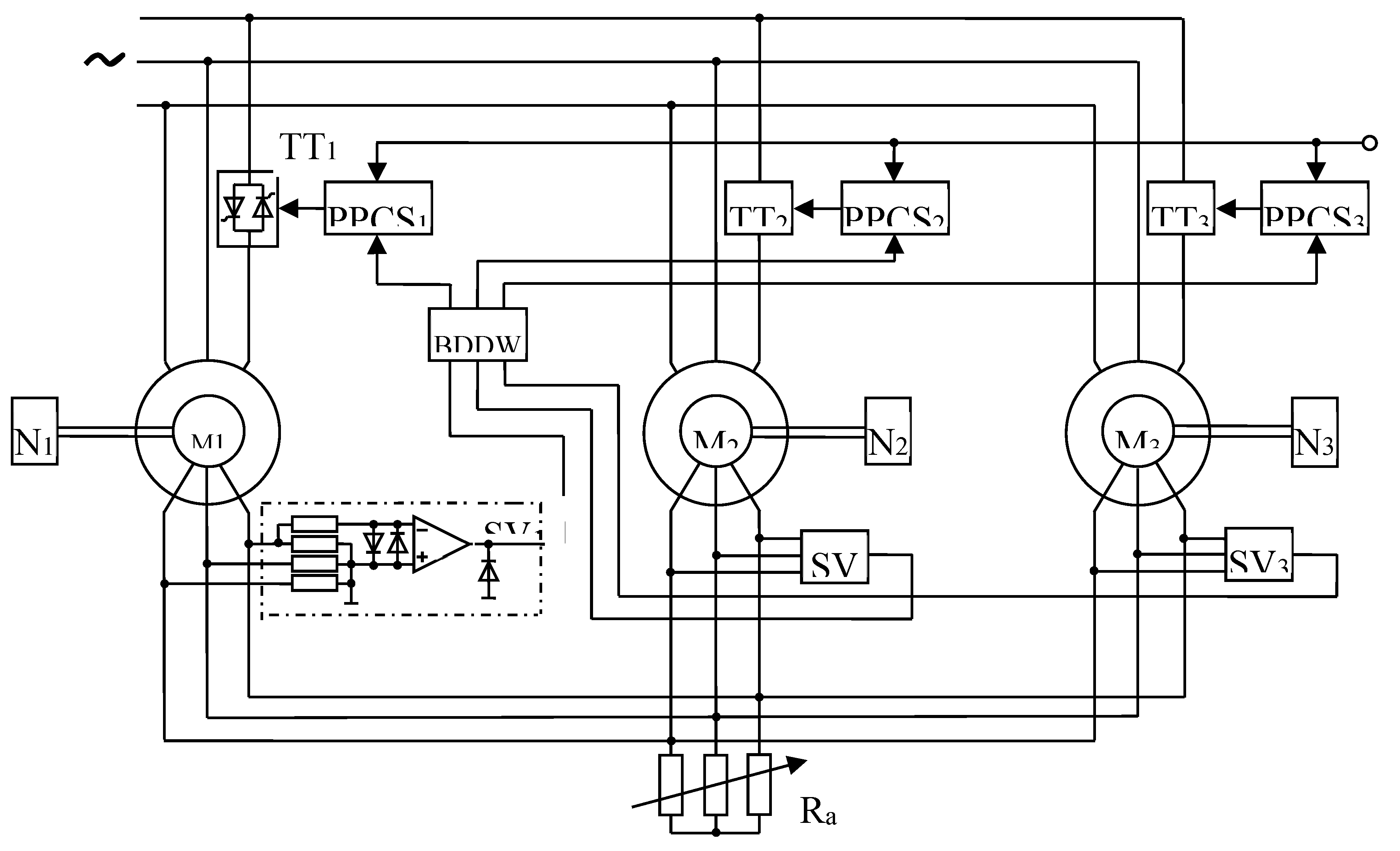
If an asymmetric voltage is applied to the stator windings of identical asynchronous motors in accordance with the diagram shown in Figure 6, then when analyzing the mechanical characteristics of an asynchronous motor, the given system of asymmetric voltages can be replaced by two symmetrical voltage systems of positive and negative sequences. Both voltage systems create positive and negative sequence rotating fields, respectively. In the direction of the positive sequence field, the rotor moves, which has slip with respect to the negative sequence field, where S - is the slip relative to the positive sequence field.
where marked:
М1, М2, М3 – is the asynchronous motors with a phase rotor;
N1, N2, N3 – is the motor shaft loads;
SV1, SV2, SV3 – is the rotary voltage sensors EMF;
ТТ1, ТТ2, ТТ3 – is the back-to-back thyristors;
BDDW – is the block for determining the degree of workload;
PPCS1, PPCS2, PPCS3 – is the pulse-phase control systems;
Ra – is the total rotor resistance EOS.
Expressions for the moments of three induction motors from the positive and negative sequence fields in the MAEDs SR system can be found based on the T-shaped equivalent circuit shown in Figure 6. In this case, the torques of the engines will have the form: direct sequence:
where М1,2,3 - is the torques of the first, second and third engines; Mmax - is the maximum torque of the motors; S - slip of asynchronous motors; , - is the maximum slip of the engine separately and in the system of the electric working shaft; θ1,2,3 – is the angular displacements of motor rotors; θL - is the angular position of the rotor of the corresponding motor.
Total moments, i.e., The torques of each motor in the MAEDs SR system with unbalanced connection of the stator windings are defined as:
As can be seen from the expression of the moments of asynchronous motors in MAEDs SR, the moments of the motors consist of asynchronous and synchronizing components (the second terms are proportional to the sine of the angular position of the rotors). As the graphs of mechanical characteristics during synchronous braking have shown, they coincide and overlap each other as rectilinear curves with a multi-motor version and prove the correctness of the theory as asymmetric braking in a single-motor version.
5. Conclusions
Based on the T - figurative equivalent circuit:
1. Analytical expressions for torques, stator and rotor currents of asynchronous motors of a coordinated rotation system are obtained.
2. An algorithm for calculating the main electromechanical ratios has been compiled, mechanical characteristics have been constructed for various values of rotor resistance, supply voltages and angular positions of the rotors of asynchronous motors of a coordinated rotation system.
3. Multi-motor asynchronous electric drives with thyristor converters with increased synchronizing capabilities have been developed.
4. A multi-motor asynchronous electric drive with preliminary synchronization, synchronous starting and braking has been developed.
Author Contributions
Conceptualization, T.K.; methodology, N.N. and A.Z.; software, N.N.; validation, B.A. and N.R.; formal analysis, A.Z. and K.T.; investigation, N.R. and K.T.; resources, Z.O. and K.I.; data curation, Z.O. and A.Z.; writing—original draft preparation, N.N., B.A., K.T. and A.Z.; writing—review and editing, N.R., Z.O. and K.I.; visualization, N.N. and K.T.; supervision, A.Z.; project administration, A.Z., N.N., Z.O. and K.T.; funding acquisition, B.A., K.I and N.R. All authors have read and agreed to the published version of the manuscript.
Funding
This research was funded by the Almaty University of Power Engineering and Telecommunications, named after G. Daukeyev.
Data Availability Statement
Data are contained within the article.
Acknowledgments
This work received financial support from the Almaty University of Power Engineering and Telecommunications, named after G. Daukeyev, and was performed at the Institute of Energy and Green Technologies, which is gratefully acknowledged by the authors.
Conflicts of Interest
The authors confirm that they have no conflicts of interest with respect to the work described in this manuscript
References
- Zanasi, R.; Azzone, G. Field oriented control of a multi-phase asynchronous motor with harmonic injection. IFAC Proceedings Volumes 2011, 44(1), 6160-6165. [CrossRef]
- Levi, E.; Bojoi, R.; Profumo, F.; Toliyat, H.A.; Williamson, S. Multiphase induction motor drives – a technology status review. IET Electric Power Applications 2007, 1(4), 489-516. [CrossRef]
- Xu, H.Sh.; Toliyat, H.A.; Petersen, L.J. Rotor field oriented control of five-phase induction motor with the combined fundamental and third harmonic currents. Proc. IEEE APEC 2001, 1, 392-398. [CrossRef]
- Kong, W.K.; Wang, J.X.; Kong, D.; Cong,Y.Y.; Feng, Sh. Sh. Motor shifting and torque distribution control of a multi-motor driving system in electric construction vehicles. Advances in Mechanical Engineering 2021, 13(6), 1-11. [CrossRef]
- Shu R, Wei J, Tan R; et al. Investigation of dynamic and synchronization properties of a multi-motor driving system: Theoretical analysis and experiment. Mechanical Systems and Signal Processing 2021, 153(6), 107496, 1-18.
- Xie, Z.; Shu, R.; Huang, J.; Fu, B.; Zou, Z.; Tan, R. Dynamic response and synchronizing characteristic for the dual-motor driving system in non-inertial system. Machines 2022, 10, 620. [CrossRef]
- Khamudkhanov, M.; Sapaev, B.; Umarov, B. Multi-motor drive with common inverter for pumping unites. IOP Conference Series Materials Science and Engineering 2020, 862(6), 1-9, 062035. [CrossRef]
- Aisayev, Y.; Tergemes, K.; Zhauyt, A.; Sheryazov, S.; Bakenov, K. The Impact of Replacing Synchronous Generators with Renewable-Energy Technologies on the Transient Stability of the Mangystau Power System: An Introduction to Flexible Automatic Dosage of Exposures. Energies 2024, 17, 2314. [CrossRef]
- Semykina, I.; Zavyalov, V.; Glazko, M. Gradient control of multi-motor asynchronous electric drive. Bulletin of Tomsk Polytechnic University 2009, 315(4), 65-69.
- Kuric, I.; Nikitin, Y.; Sága, M.; Tlach, V.; Bannikov, A. Development of Electric Drive on the Basis of Five-Phase Synchronous Electric Motor. Electronics 2022, 11, 2680. [CrossRef]
- Odnokopylov, I.; Dementev, Y.; Usachev, I.; Lyapunov, D.; Petrusev, A. Load balancing of two-motor asynchronous electric drive. International Siberian Conference on Control and Communications (SIBCON) 2015, 1-4. [CrossRef]
- Shi, T.; Liu, H.; Geng, Q.; Xia, C. Improved relative coupling control structure for multi-motor speed synchronous driving system. IET Electr. Power Appl. 2016, 10, 451–457.
- Wei, J.; Shu, R.; Qin, D.; Lim, T.C.; Zhang, A.; Meng, F. Study of synchronization characteristics of a multi-source driving transmission system under an impact load. Int. J. Precis. Eng. Manuf. 2016, 17, 1157–1174.
- Xiong, H.; Zhang, M.; Zhang, R.; Zhu, X.; Yang, L.; Guo, X.; Cai, B. A new synchronous control method for dual motor electric vehicle based on cognitive-inspired and intelligent interaction. Future Gener. Comput. Syst. 2019, 94, 536–548.
- Lv, Y.; Ren, X.; Na, J. Online Nash-optimization tracking control of multi-motor driven load system with simplified RL scheme. ISA Transactions 2020, 98, 251–262. [CrossRef]
- Wang, M.L.; Ren, X.M.; Chen, Q.; Wang, Sh.B.; Gao, X.H. Modified dynamic surface approach with bias torque for multi-motor servomechanism. Control Engineering Practice 2016, 50, 57-68. [CrossRef]
- Yang, Y.; Mi, Y.; Qin, D.; Yuan, A.; Li, G. Analysis of the characteristics of electromechanical-hydraulic model of multi-source drive/transmission system based on periodic excitation. Advances in Mechanical Engineering 2019, 11, 1–15. [CrossRef]
- Feng, X.; Zhuo, Q.; Liu, X.; Qian, Y.; Li, Y. Development of multi-motor synchronous control system based on network-on-chip. Proceedings of the Institution of Mechanical Engineers Part I Journal of Systems and Control Engineering 2020, 234, 1000–1010. [CrossRef]
- Ruan, J.; Song, Q. A novel dual-motor two-speed direct drive battery electric vehicle drivetrain. IEEE Access 2019, 7, 54330–54342. [CrossRef]
- Fang, P.; Wang, Y.; Zou, M.; Zhang, Zh. Combined control strategy for synchronization control in multi-motor-pendulum vibration system. Journal of Vibration and Control 2021, 28(5). [CrossRef]
Figure 1.
T-shaped equivalent circuit of three asynchronous motors with electrical connection through rotary circuits.
Figure 1.
T-shaped equivalent circuit of three asynchronous motors with electrical connection through rotary circuits.
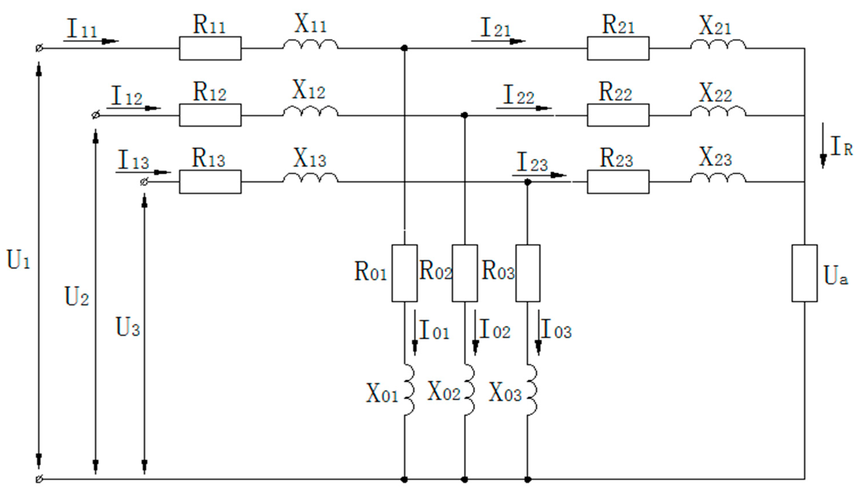
Figure 2.
Algorithm for calculating the mechanical characteristics of a three-engine MAEDs system.
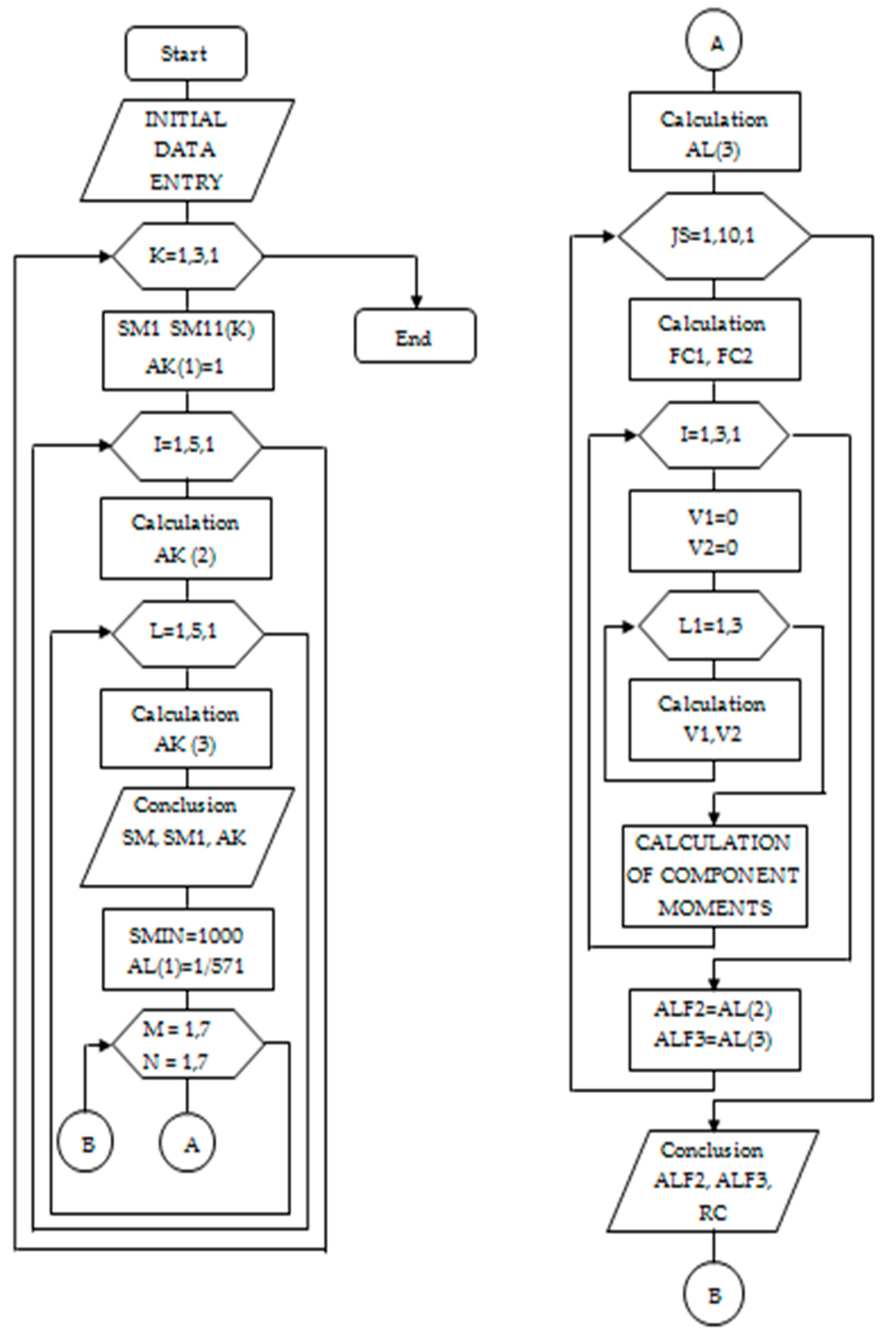
Figure 3.
Mechanical characteristics of a three-motor electric drive carding machine (CM) at different angles of mismatch and total rotor resistance.
Figure 3.
Mechanical characteristics of a three-motor electric drive carding machine (CM) at different angles of mismatch and total rotor resistance.
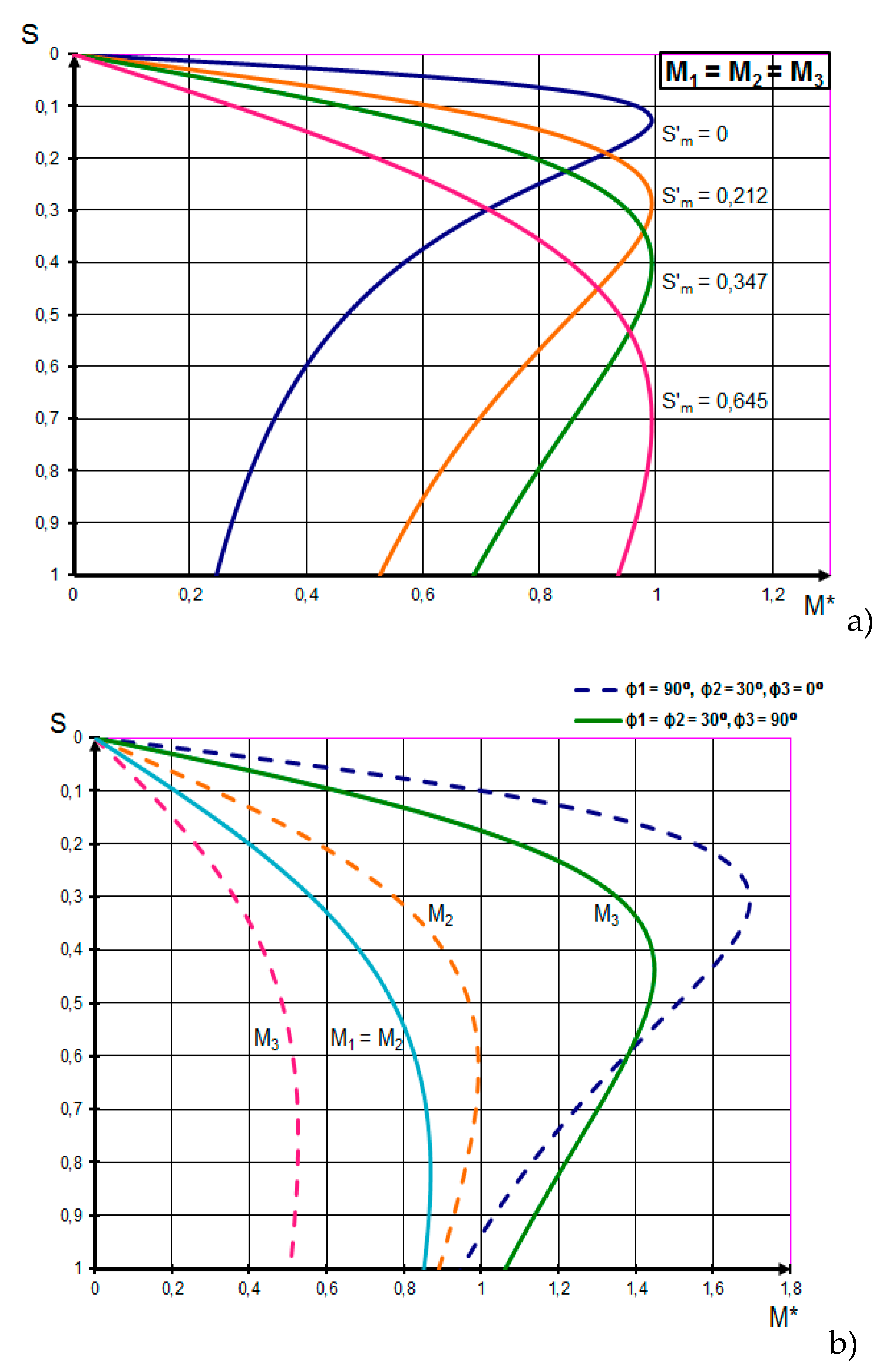
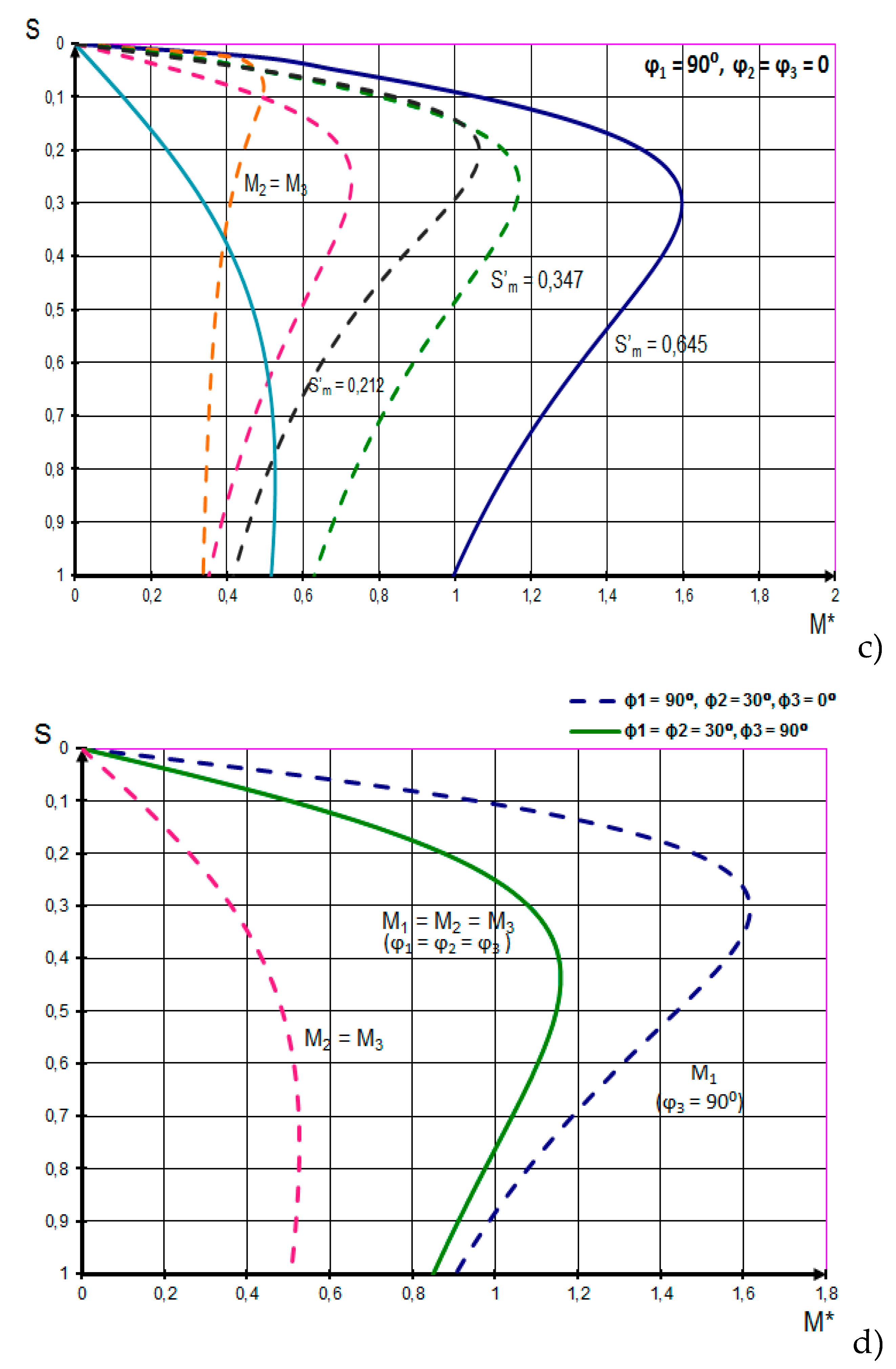
Figure 4.
Graphs of the mechanical characteristics of MAEDs with a change in the supply voltages of the motors.
Figure 4.
Graphs of the mechanical characteristics of MAEDs with a change in the supply voltages of the motors.
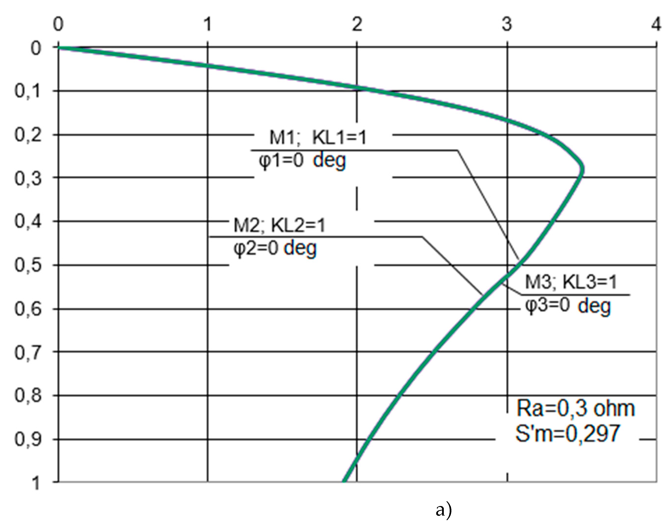
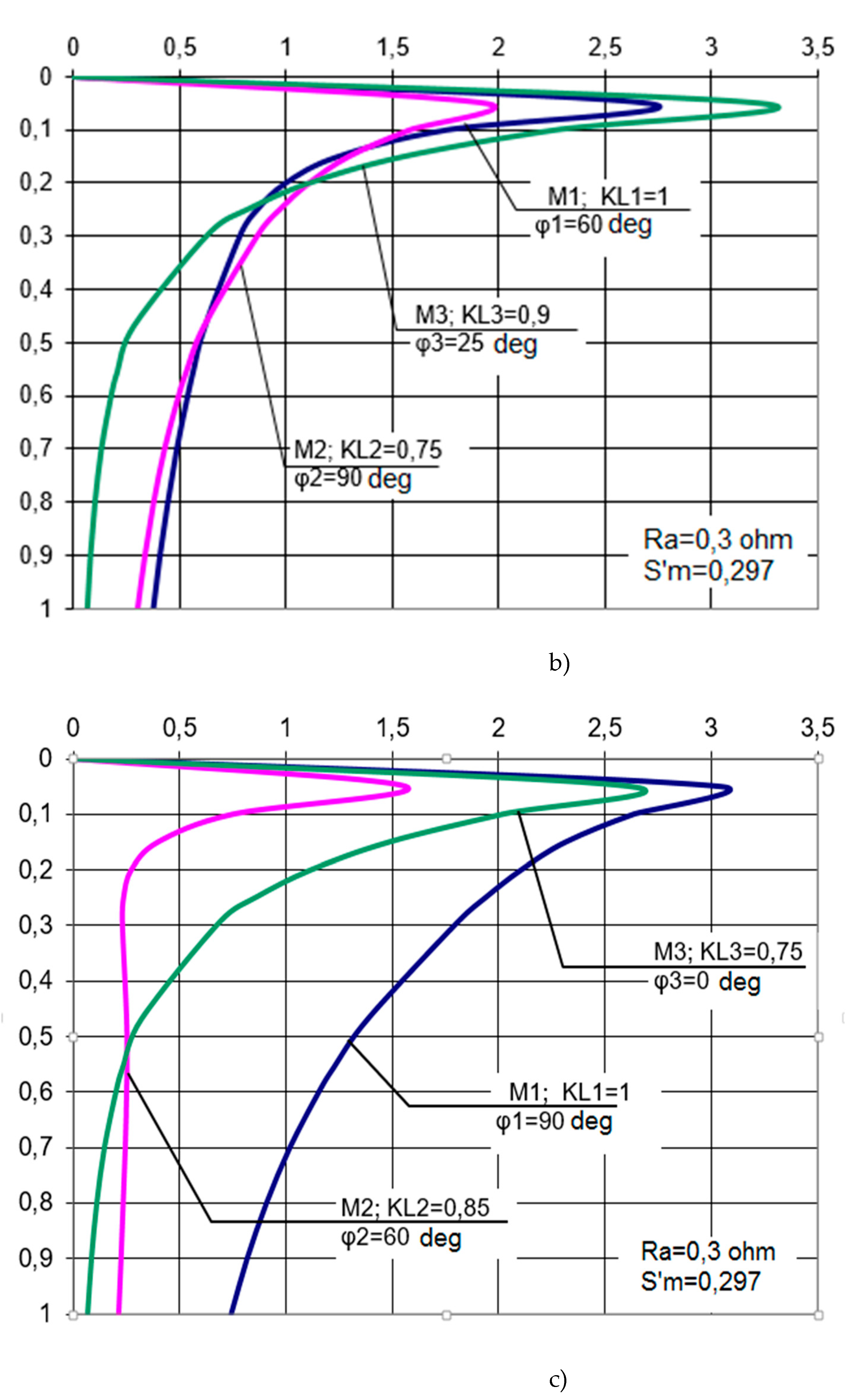
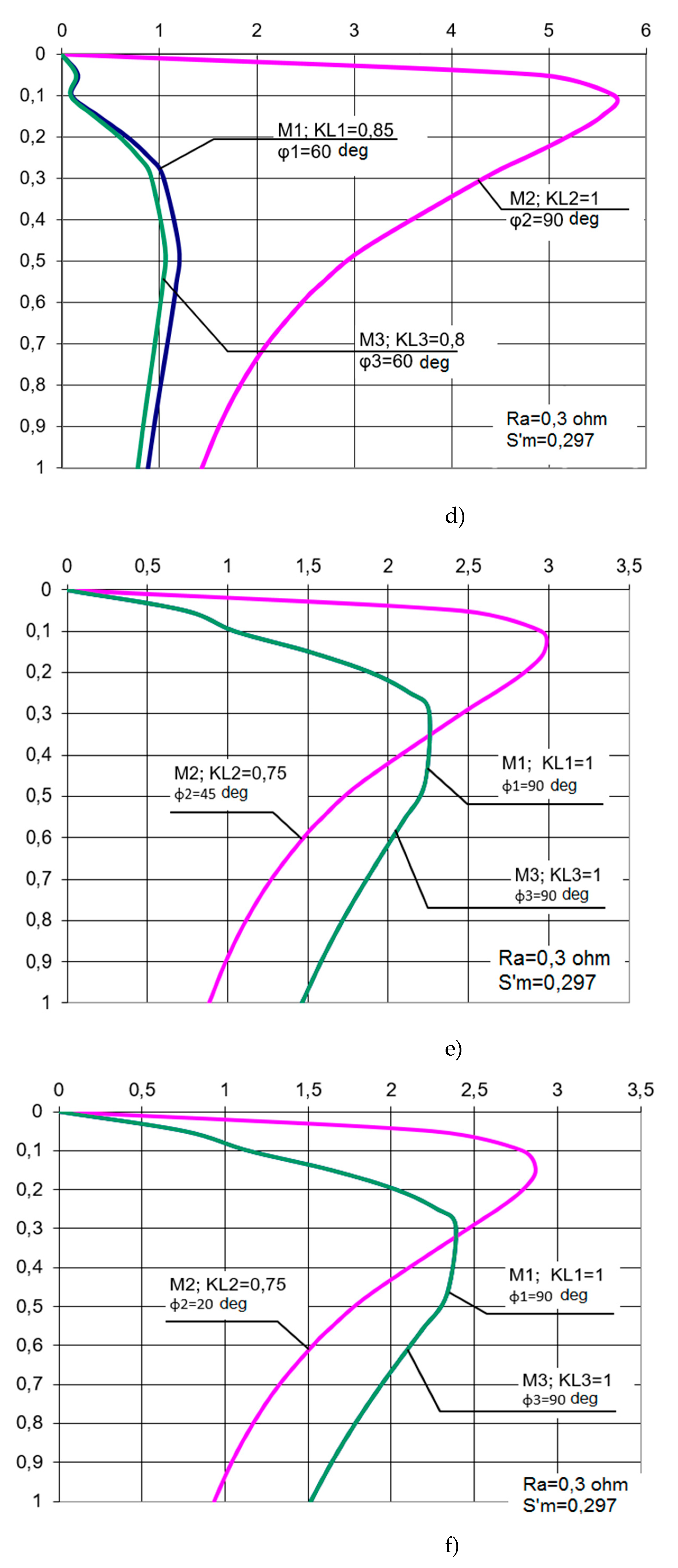
Figure 5.
Functional diagram of MAEDs with TVC with determination of the motor load difference.
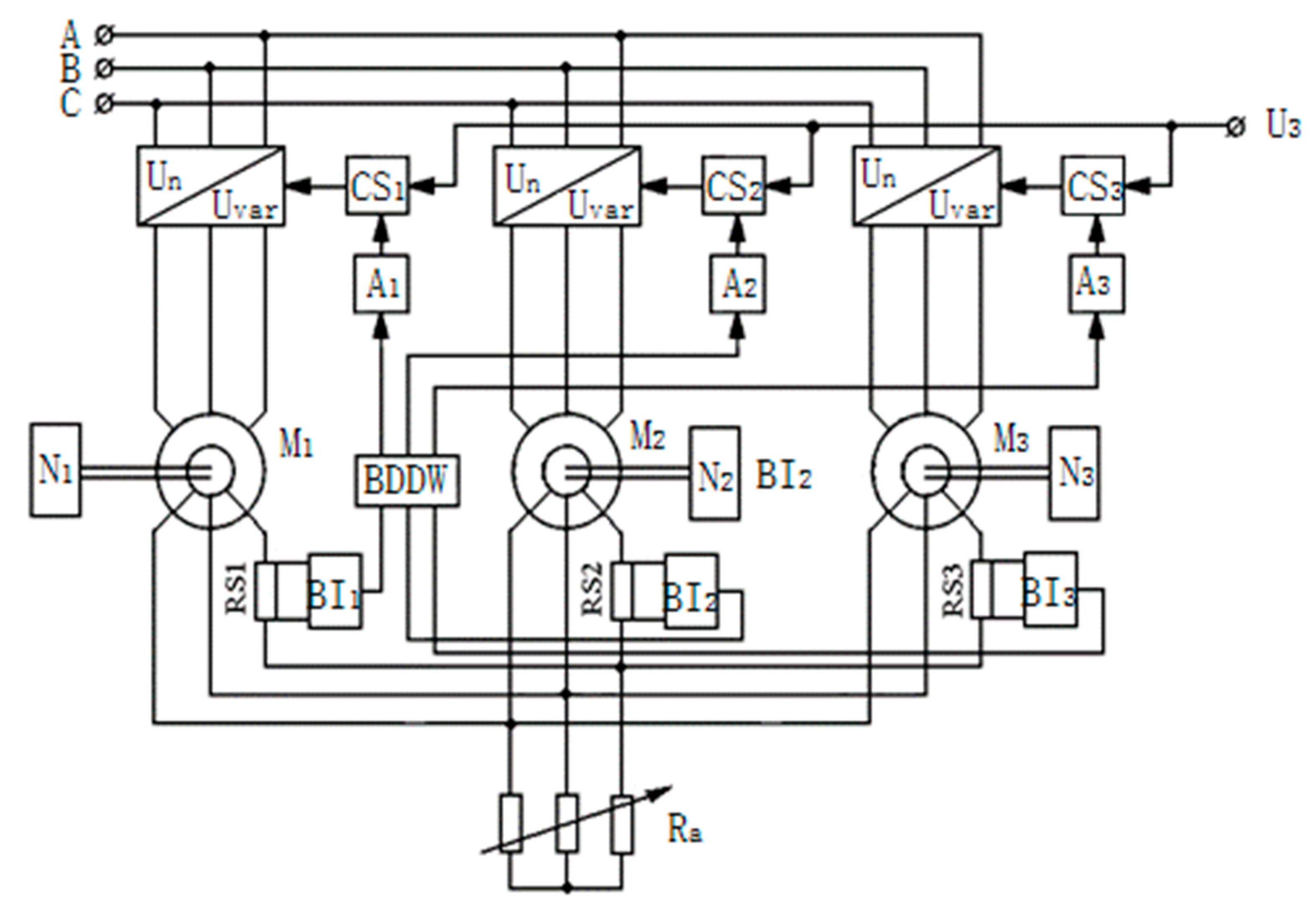
Figure 6.
Three-motor electric drive with asymmetric thyristor voltage converters.
Disclaimer/Publisher’s Note: The statements, opinions and data contained in all publications are solely those of the individual author(s) and contributor(s) and not of MDPI and/or the editor(s). MDPI and/or the editor(s) disclaim responsibility for any injury to people or property resulting from any ideas, methods, instructions or products referred to in the content. |
© 2024 by the authors. Licensee MDPI, Basel, Switzerland. This article is an open access article distributed under the terms and conditions of the Creative Commons Attribution (CC BY) license (http://creativecommons.org/licenses/by/4.0/).
Copyright: This open access article is published under a Creative Commons CC BY 4.0 license, which permit the free download, distribution, and reuse, provided that the author and preprint are cited in any reuse.
MDPI Initiatives
Important Links
© 2024 MDPI (Basel, Switzerland) unless otherwise stated


