1. Introduction
The building called “Tembo Barcelona” is located on Sant Ramón de Penyafort Avenue, in Sant Adrià de Besòs. The plot is delimited by Ramón Llull Street, Lola Anglada Street and Fernández Márquez Avenue, in an area where the housing built during the mid-twentieth century, was designed for the working class [
1]. The building’s typology consists of three floors below ground level, ground floor and seventeen floors above ground. It is therefore considered a high-rise building under local regulations, also called EGA [
2] in Catalonia. The typical floor of the project has a built area of approximately 1.300m². The structure was designed mainly using reinforced concrete slabs, with the exception of some metallic or mixed (steel-concrete) elements. The building contains some singularities, such as:
- -
Excavation of three basement levels, very close to the sea.
- -
Abatement of the water table by infiltration.
- -
High-rise building.
- -
Wind exposure on the second line of the sea.
- -
Rest areas in the corridors resolved with three-dimensional metallic structure.
- -
Shoring of a 14-storey cantilevered column.
This last singularity is the main reason for writing this article. One of the pillars that is located right at the entrance of the building, cannot reach the head of the containment walls, because it would be visible on the outside, making the building heavier. The elimination of this pillar, which can be understood as unnecessary, makes access lighter, establishing a dialogue with the podium that is being advanced. For this reason, it was proposed to create a discontinuity on the lower floors. This decision generates a cantilever of almost nine meters on the fifteen upper floors. It was not possible to introduce downstand beams on each floor. It was preferred to introduce a triangulation on the façade that is finally hidden behind the outermost skin of the terraces.
The shoring was conceived in agreement with the main architect author of this building, Jaume Font i Basté (D388 Arquitectura), foreseeing two diagonals: one ascending and one descending of shorter length, which circumvent the windows of the building, and form an obtuse triangle in elevation. During the executive project phase, other solutions were discarded. Specifically, introducing active forces [
3], to avoid using technological solutions that could delay the work. The floor plan of the building has columns at distances that do not allow an active solution to be generalized on each level, and in a sufficiently representative part of the project. The construction company that was awarded the work is called Copcisa. The company undertook the entire work from the first day to the end of the work. Cullaré Sala Structures completed the metallic structure, that was calculated by BEST Costales Jaén.
2. Description of the Structure of the Building
The first impression when you analyze the solution used, is that other triangulations are necessary towards the opposite part of the cantilever, acting as counterbalance of the system. No other diagonals are necessary than the described. The consideration of a spatial work of the slabs will be reasoned later to solve the problem.
The V-shaped floor plan is grid by Column distance each approximately 7.2m and up to 8m in some specific locations. A single span and two cantilevers, one on each side, which reduce the positive moment in the center of the span, form the typical cross section of the floor. Slender concrete columns were designed, taking advantage of the fact that the concrete cores stiffen the building. The horizontal structure was designed using solid reinforced concrete slabs for several reasons: because the required fire stability was 120 minutes, to reduce its thickness compared to other lightened options, thus slightly increasing the free height of each slab favoring the passage of the facilities, and finally and to a lesser extent, for acoustic reasons. Hydrostatic thrust, as well as the general excavation are also reduced using thinner slabs. Three concrete cores, placed where the elevators and stairs are located, brace the building horizontally. Seismic forces were not taken into account in the design phase of the building, as it is not mandatory according to current regulations NCSE-02 [
4]. The high exposure to wind [
5] suggests that earthquake effect would not be a more unfavorable hypothesis than wind hypothesis considered in the calculation.
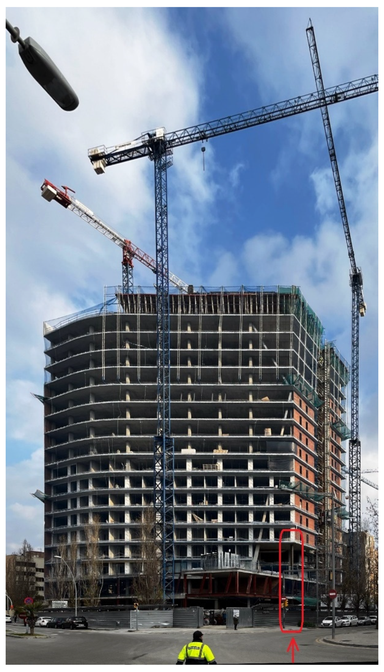
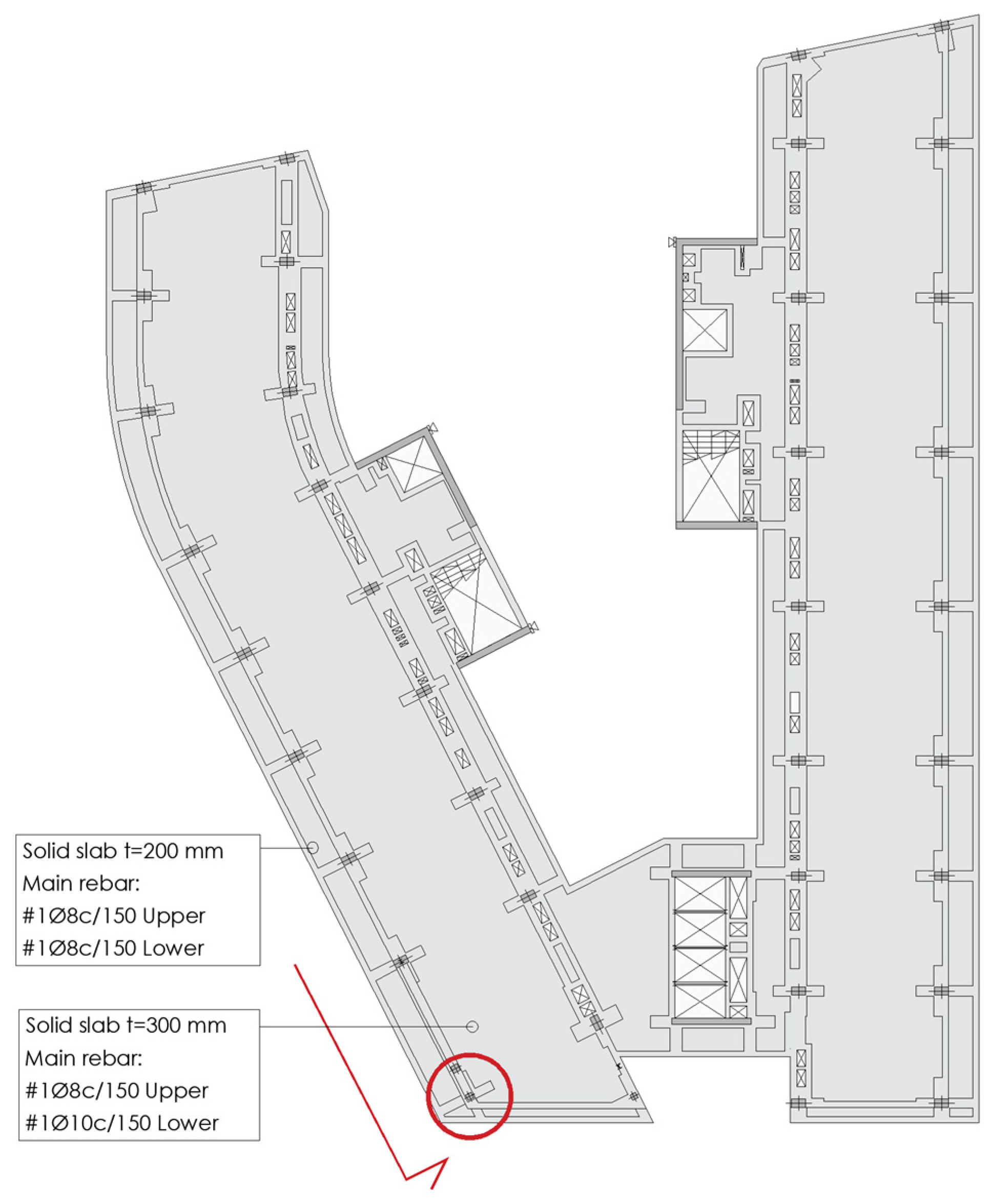
The column that does not have continuity is indicated in
Figure 1 with a red circle; it is located in a corner of the building's floor plan. In order to complete the construction of this area, a temporary column was positioned. Formed with two HEM-280 steel sections, the column has fourteen meters high. The profiles were joined together by welding their flanges, forming a box that increased its buckling resistance. This column, which was the equivalent length of four stories high, rested on the end of a slab near the crowning girder of the slurry wall. An external provisional metal cantilever beam was proposed at the foot of the metallic column, which would be removed when the deshoring process was finished (see
Figure 1 “Cantilever Beam” in the bottom right). Meanwhile, the column was horizontally fixed by the ground floor ceiling and the first-floor ceiling, to work with six meters buckling length. To fix each level, four vertical pieces of neoprene were placed on the perimeter of the hole left in each slab, maintaining contact between slab and column. The temporary prop remained in service during the construction phase, until the seventeenth floor was reached. Once the main structure was completely finished, it was time to remove the prop.
The tributary area of a typical column is estimated at 30m2, so the axial strength of each floor is evaluated at 530kN. This force is not real, because the diagonals cross the slabs, they also give them support, and therefore reduce the load. This calculation is made to know that the mobilized force reaches 8,900kN in ELU, considering in the sum the weight of the façade of that area.
The maximum axial compression supported by the provisional strut, is justified below:
During the definition of the executive project, it was determined that the strut would be eliminated with oxycutting [
6] using a diagonalcut method, without taking any added precautions. As an added precautionary measure, deformation would be checked by topography or by a precision gauge strongly fixed to the ground. An inclined cut is usually executed to remove the temporally prop. If a horizontal cut were made, it would not work, because it has been proven that, once the column is cut, both ends are rejoined due to the deformation of the system. While the inclined cut causes both parts to slide on the cutting plane, automatically obtaining the separation of the system.
It is common not to take any precautions when a prop is shored, since it must be considered that the calculation first, and the execution later, have been sufficiently checked. But also, because at the time of cutting, the structure is barely loaded with half of the actions taken into account in the calculation: permanent loads and live loads are non-existent. In addition, the regulatory safety coefficient during the construction phase is lower [
7]. As it is a very delimited area, the live loads can be eliminated, preventing access on each floor.
However, contrary to what has been explained so far, during the construction phase it was considered that if the final deformation observed in the system, once the undercutting had been carried out, was considerably greater than calculated, there would be no way to recover that deformation or, at least, to stop it. The decision was not made for reasons of calculation reliability, but under the consideration that the shoring worked as a spatial system, and could eventually have a different response to that analyzed in the calculation model. And in case the construction process could generate a different behavioral situation. It's probably fair to say that the total cost of the operation, which amounted to approximately twelve thousand euros, was well invested in order to have a clear document in the future that would rule out later problems.
When it is said that it is a spatial system, it means that the building does not have any other diagonal than those shown in the portico, the moment of overturning being retained by the slabs, which in turn are embedded horizontally in the core. It is this core that prevents the building from tipping in the direction of the overhang. It is also responsible for transmitting up to 80% of the wind actions to the foundation.
On some floors these leaning columns will be partially visible in some rooms, right on the façade plane, between the living room and the exit to the terrace. In 1966, at the John Hancock Center Tower in Chicago (Fazlur Rahman Khan, Architect, Skidmore, Owings and Merrill, Structure), there was a concern about what would happen to these rooms that incorporated diagonals in their facades during the calculation and design process. It was one of the first high-rise buildings to experiment with a solution with exterior bracing, a solution that would later be used by other buildings, as in the case of the Hotel Arts in Barcelona, the work of the same authors. The end result was that not only were there no problems in their demand, but they were also the most sought-after spaces, as these diagonals incorporated a formal and spatial quality to the interior, different from that of any apartment in Chicago [
8].
Figure 2.
Image of the construction process of the hotel already finished in January 2022. Indicated with a red rectangle the vertical provisional column that has not yet been removed, can be seen.
Figure 2.
Image of the construction process of the hotel already finished in January 2022. Indicated with a red rectangle the vertical provisional column that has not yet been removed, can be seen.
3. Description of the Frame That Contains the Shoring
The frame that completes the shoring, is formed by:
A composite steel -concrete vertical column (A), which goes from foundation to the roof. It was designed composite, in order to facilitate the union with the rest of the metallic diagonals, which will be defined below.
An inclined steel diagonal (B), HEM 400/320 with added plates, which goes from the second floor to the thirteenth floor. It is 36.2m long and 78º inclined. In the foot it is born from the column described above (A), and in the head, it coincides with the beginning of the vertical metallic tension bar (D) and with the end of the top diagonal (C) that will be described below.
An inclined steel diagonal (C), HEM 320 with added plates, which goes from the head of the previous diagonal to the ceiling of the sixteenth floor. It is 15m long and 60º inclined.
A vertical steel tension bar (D), HEM-200 with added plates, that completes the frame, which goes from the third floor to the twelfth floor ceiling. Above this plant, it continues as a compressed column. As a particular characteristic, it is worth mentioning that this element will be compressed during the construction phase, and will be subjected to traction in its final state.
The entire vertical of the brace (D) was built with a slight counter-deflection so that at the time of de-shoring, that point did not have excessive deformation. The final axial forces that were calculated during the definition of the executive project, both in the work process and in the final phase, are detailed below in the
Table 1:
During the design process, it was considered that the final axial force transmitted by the provisional prop could be evaluated about 3,000 and 6,800kN in SLS (Serviceability Limit State). The reason why there was such a high variation between the two results corresponds to the fact of whether or not the construction process was considered. Finally, the most unfavorable case would be taken, in anticipation of possible delays when carrying out the shoring.
4. Description of the Structural Solution Adopted for the Unshoring Process
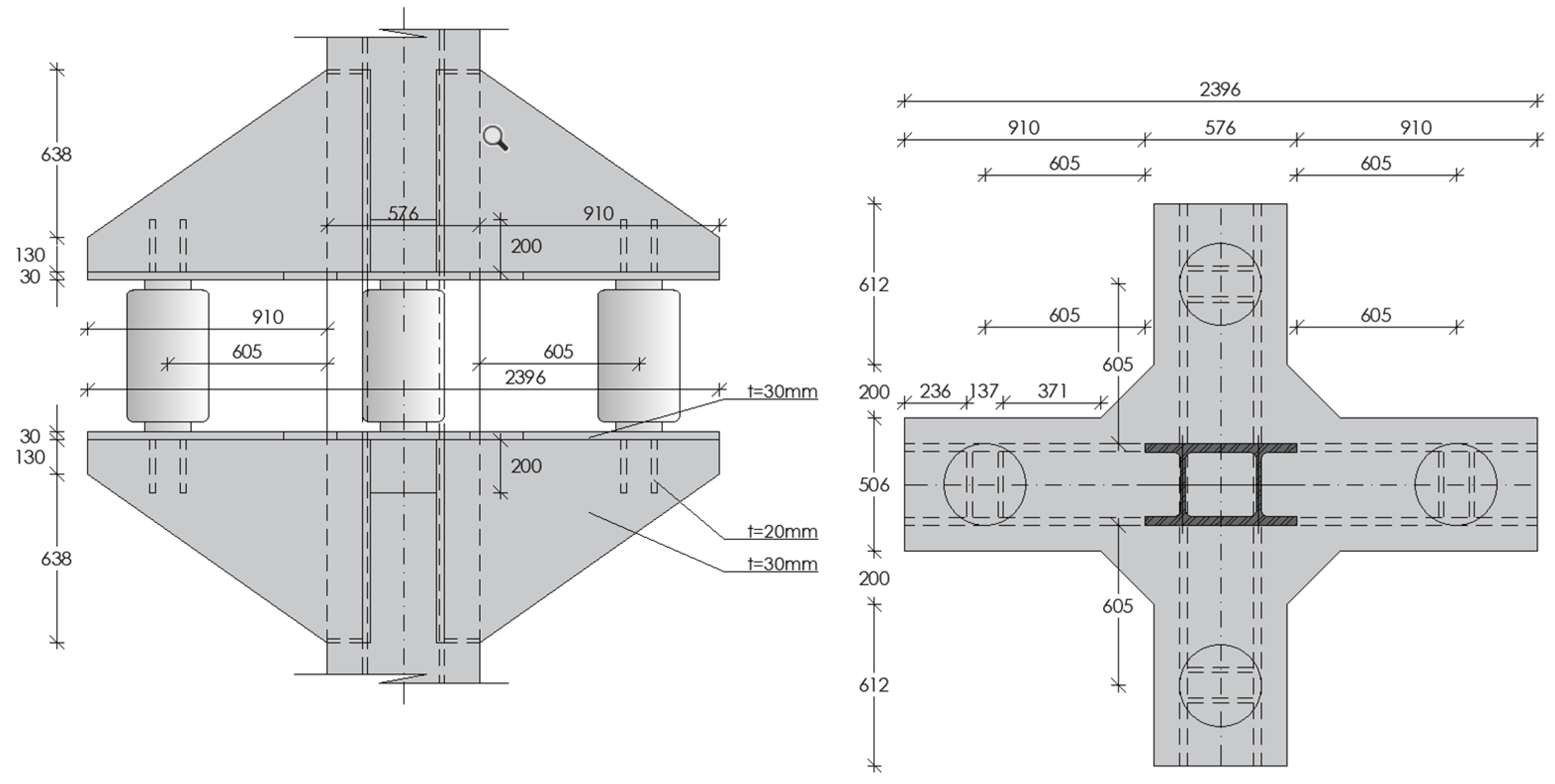
During the construction phase, the decision was made to progressively remove shoring, placing two pairs of four cantilever beams in the two main directions, and on two levels separated by about 575mm [
9,
10,
11,
12] This distance was determined by adding the maximum deformation observed in the general calculation models, the height of the jack necessary for the required force and finally, adding a margin in accordance with the maximum acceptable stroke. These types of techniques are commonly used in many buildings, as is the case with many historic one’s [
13,
14,
15].
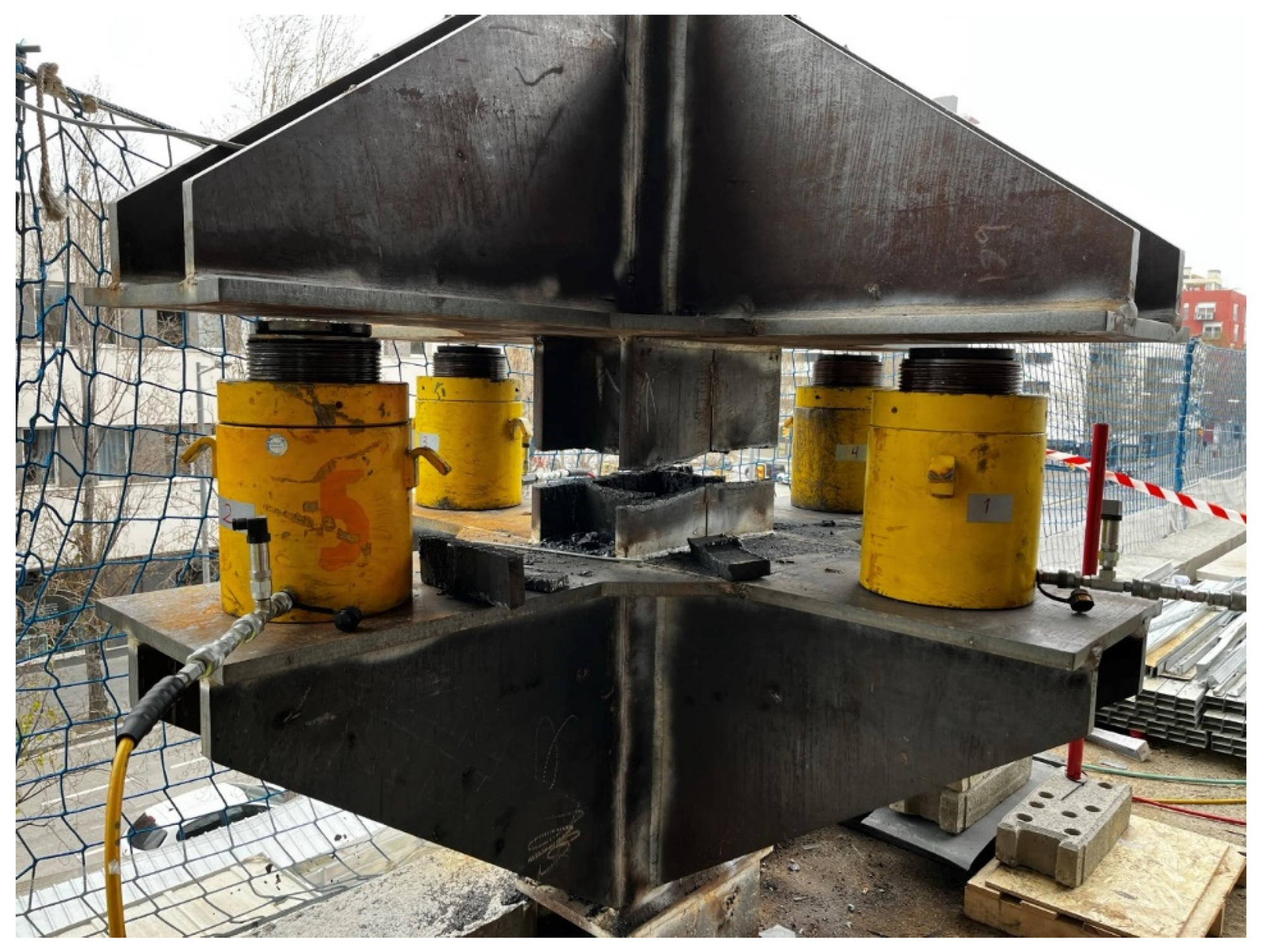
Figure 3.
Proposal for the cantilever beams, made by GMK Associates and 3Stech.
Figure 3.
Proposal for the cantilever beams, made by GMK Associates and 3Stech.
The control equipment [
16] proposed by the company 3Stech Smart structural Sensing technologies, to monitor the process, is detailed below:
Four Hydraulic pistons of 3.000kN capacity each [
17,
18,
19]. They were placed in a cross-shape form, one on each arm of each support. They had a maximum stroke of 150 mm, and a maximum opening of 575 mm.
Four strain gauges (S.G): These are sensors that determine the axial load of the inspected elements, depending on the elongation observed. They have been placed according to
Figure 1: in the head of the tension element that is an extension of the provisional column (S.G. nº1), in the web of the temporary column (S.G. nº2), between the cantilever beams (S.G. nº3), and in the inclined column (S.G. nº4).
Four displacement transducers: They control the vertical movement of the analyzed points, in this case, the tip of the metallic cantilevers beams, getting to know at all times of the process the inclination of the plane formed by the four beams.
Four pressure sensors: They give information on the pressure of each piston, which can be corrected at any time. One on each metallic cantilever beam.
All the information was recorded on a device connected to the sensors described above, which gave information at all times during the intervention. The verification of the calculus of the cantilevered beams was carried out manually, as shown below, using the method " cantilever beams with unstiffened web", which was described by Dr. Francisco Quintero in the UNEDguides [
20] , and which was subsequently included in the Spanish steel regulations EAE [
21] in its article 61.5. “Support on unstiffened bearing”
As each bracket has 2 plates in its web [
22,
23,
24,
25,
26], it can withstand a shear of approximately 6,340kN. Considering the four corbels, 25,360kN would be reached. Apparently, it can be understood that this is an excessively high figure. Later it will be understood that this oversizing was a precaution for the process.
The final deformation was estimated between 20 and 30mm. It was important that the maximum expected deformation was defined in a loose way, since the piston had to be able to allow this stroke with sufficient clearance: if the piston had a maximum allowable stroke less than expected, it could not be removed and the process would have failed. This deformation was difficult to calculate, because the construction process of the concrete structure took about six months to achieve, and while some columns were concrete, others were composed of metallic-concrete and had a different time-dependent deflection. Therefore, the instantaneous deformation depending on the real Young's modulus, the construction process and shrinkage and creep of the material will influence the final result.
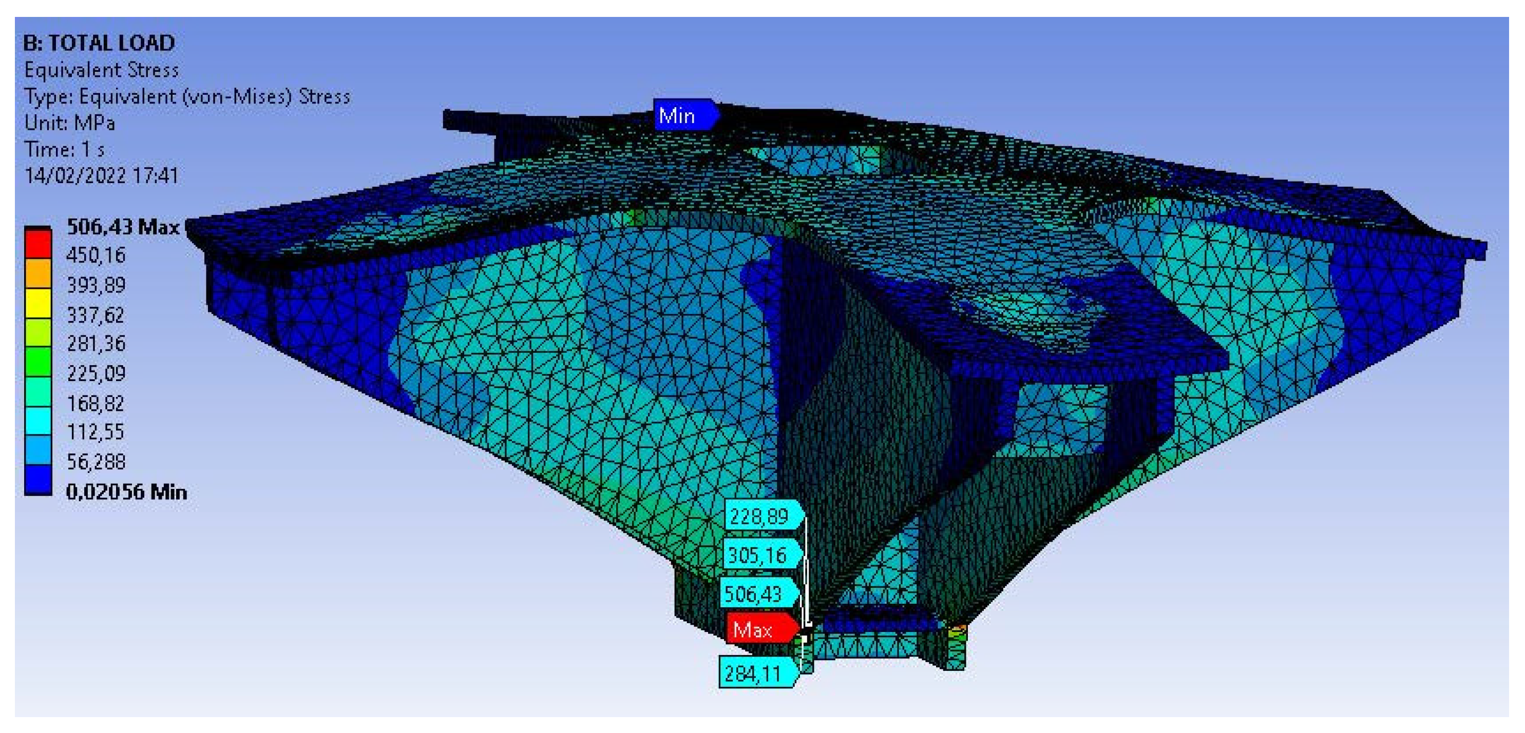
In order to be able to contrast the results that were considered during the work by using formulas, a finite element model was generated under a university license, several months after the end of the work. Therefore, it is a verification made a posteriori for the preparation of this article. It was carried out with the ANSYS program [
27], which considers the buckling of the plates in second order. The maximum stresses obtained at full load are generally less than the yield strength of the material f
y=355N/mm
2, as shown in
Figure 4. At a very specific point, tension peaks of around 506N/mm
2 are observed, but their location allows an integration of stresses in the area. This analysis gives a result lower than the maximum allowed stress. The results obtained are in any case in accordance with those expected during the construction phase.
5. Description of the Unshoring Process
During the previous days of the implementation of the shoring process, the corresponding tests of the welds and the designed metal elements were carried out. The result was positive in all cases. The next step was to ensure that the temporary column was firmly welded to the first supported floor: if the column was cut, it was important that the upper section did not fall on the workers.
On March 14, 15 and 16, 2022, the process of pre-loading the cantilever beams was carried out, as was the subsequent de-shoring process.
- Pre-loading process and subsequent unloading of the cantilever beams: During March 14, 2022, all control elements were placed and checked. The system was then placed under load using four steps of equal magnitude, with a final load of 6,800kN. Once this force was reached, it was unloaded without having started any cutting process. This previous step was, so to speak, the “insurance” of the “insurance”, that is, a load test of the system. The proposal can also be understood as a prestressing of a metal structure for its control [
28].
During this process it was possible to verify a slight warping, barely insignificant, of one of the plates of one cantilever beam. No image is attached since it was barely noticeable. This warping occurred when one of the sheets was subjected to a greater compression than was finally necessary, possibly because the piston was not perfectly centered on the beam and one of the two sheets was more requested than expected.
In this type of joint, it is always interesting to introduce a small stiffener at the beginning and end of the outside of the diagonal edge, to improve the embedding of the core with the base plate and with the column. Despite the fact that the theoretical model worked, and that the matrix calculations in the second order did not represent stability problems, this slight deformation was appreciated and was not a cause for concern, nor for subsequent repair, because the force introduced was greater than calculated, expected and finally obtained. Therefore, this negligible unexpected deformation made the loading process a good practice.
Finally, the load introduced into the system was removed, which "self-compensated" without altering the system. It is necessary to say that the prop was checked and had enough margin to be able to receive the prestress load plus the one introduced in a very localized area, between the metallic cantilever beams.
- Column cutting process: On the following day, March 15, 2022, after placing and checking all the control elements, as well as the pistons, a prior force of 900kN was introduced to the cantilever beams, to pre-load the pistons. This action represented approximately 13% of the final estimated load. Once the entire system had been checked, the space remaining between the two groups of four brackets was cut with oxyfuel. The column cutting process was carried out at a height of 1,2m above the first-floor ceiling, that is, in the lower part of the double height, making two flat cuts about 150mm apart from each other. In that position the oxyfuel team could work comfortably. First, an outer flange was completely removed from an HEM section. Then the opposite flange of the other HEM section, to finish cutting the four flanges. In this way, this section was weakened, allowing it to rotate itself. Finally, the central core was removed, completely freeing the column, progressively transferring the action to the pistons.
The load that these pistons finally transmitted was 2,825kN, slightly less than half of what was expected. On each floor, a live load was foreseen, as well as a dead load, which in the end was only applied to some of the lower floors. The construction process was also decisive in this reduction, since the structure was loaded progressively, and not completely, as usually happens in a matrix calculation model.
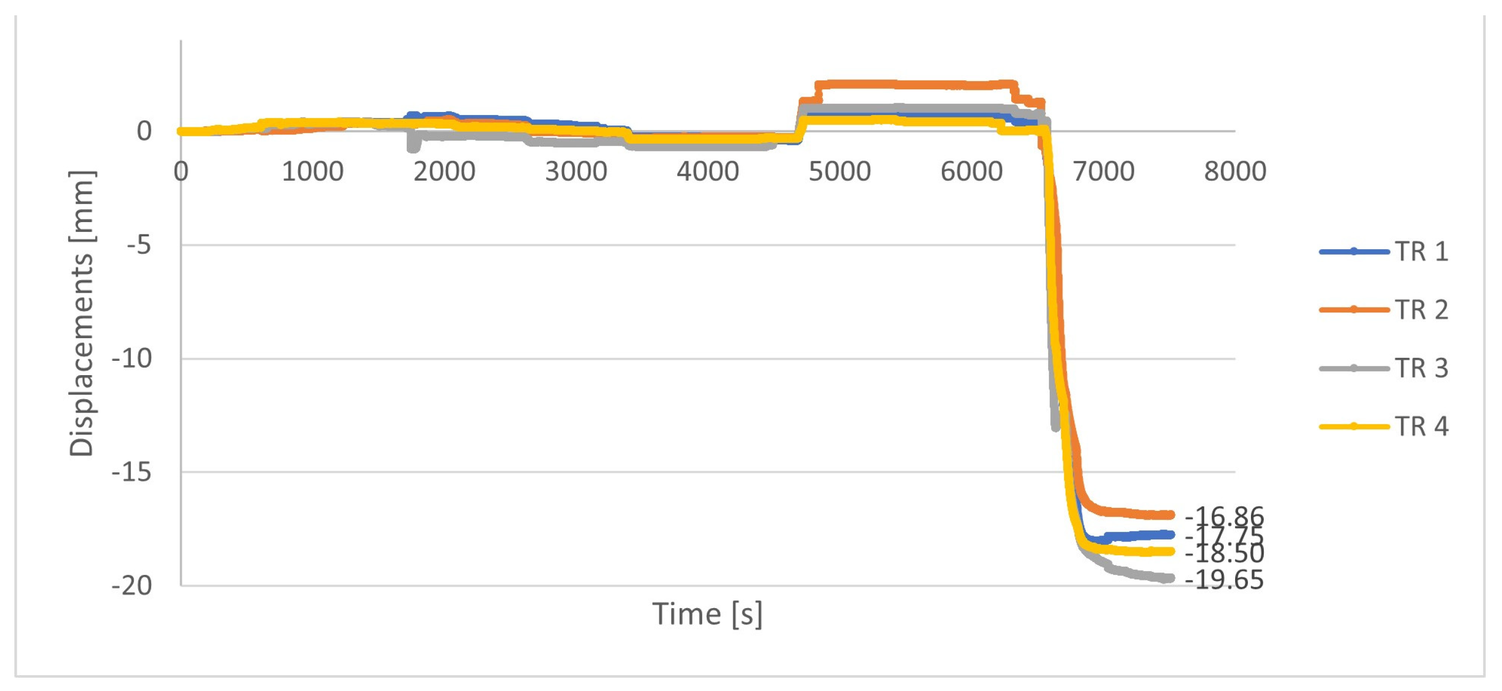
During the cutting process, no load increases or significant movements were detected until approximately 4,800 seconds (80 minutes) of process were reached. Movements of approximately 2mm were observed.
After this point and until 6,500 seconds (108 minutes) of process, the movement stabilized at the previously defined figure, between -16.8mm and -19.65mm. This deformation is insignificant for the final lowered load. It also gave us an orientation of the final deformation of the shoring when the building was fully loaded.
Figure 5.
Deformations observed in the four pistons during the cutting process. The results were recorded by the transducers, one placed in each piston.
Figure 5.
Deformations observed in the four pistons during the cutting process. The results were recorded by the transducers, one placed in each piston.
At the end of the work of cutting the provisional column, and after a reasonable amount of time had passed, the load was progressively removed from the pistons, observing a final deformation of the structure of 18mm, which was less than the maximum expected in the worst case, 30mm. The pistons were left about 10mm from the structure for 48 hours, in anticipation of possible settlements adjustments. There was no significant increase in deformation, although there was a slight variation in the distribution of stresses in the structure, as can be seen in the following
Table 2:
6. Results and Discussion: Follow-Up of the Deformation in the Following Days
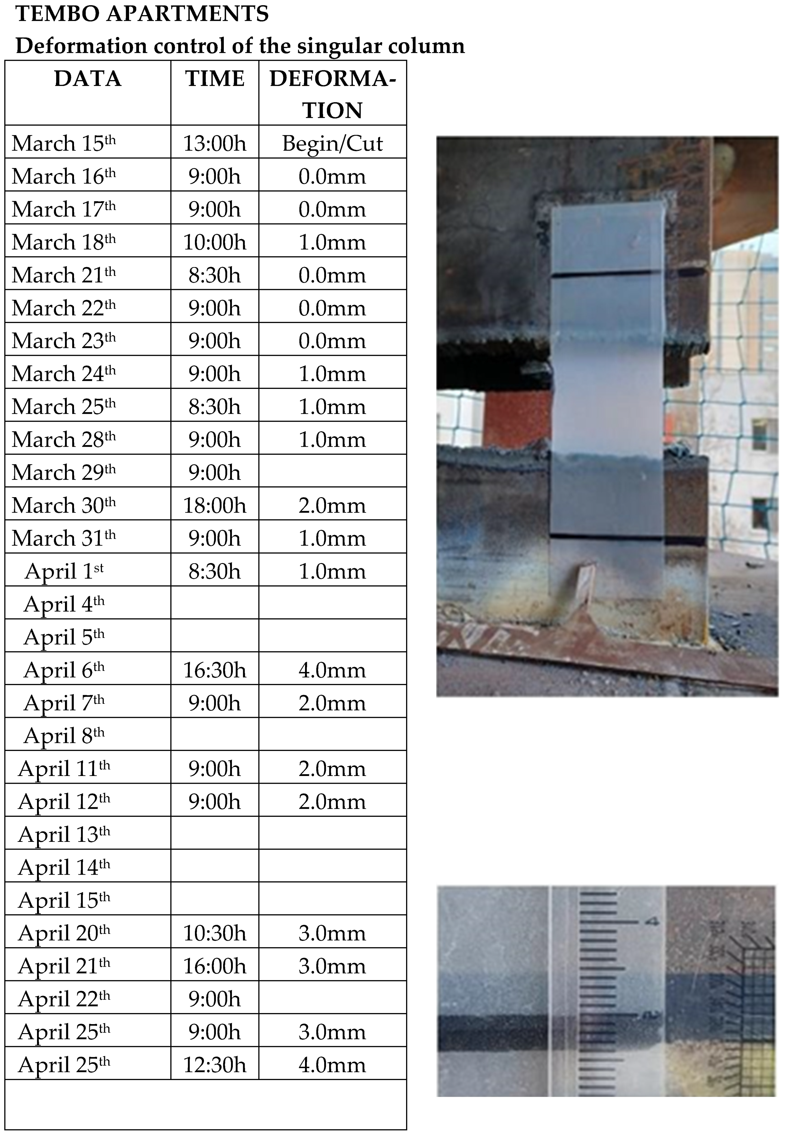
During the next day, as a safety measure, the pistons were not removed as shown in
Figure 6. This decision was considered so that if the structure were to settle suddenly, subsequent corrective action could be taken, leaving the structure momentarily retained. Since the hydraulic pistons had to be used urgently on another job, and since renting more days would significantly increase the final cost of the operation, the pistons were replaced with pieces of HEB sections, leaving a separation of approximately ten millimeters from the upper cantilever beams. Thus, if the system went down due to some unconsidered problem, the piece remained stabilized without the possibility of falling.
The deformations observed during the following month were variable, but in no way understood as a process without end. The changes that were collected in the reading, and can be found in
Figure 7, were attributed to several factors:
- -
Time difference: It seemed that solar radiation might have affected some cases.
- -
Disposal of materials in various levels: During the days after the cut, some partition walls were built that increased the weight, and therefore the deformation of the cantilever area.
- -
Small inaccuracies in the measurement: Although the measurement system was at all times careful and efficient, as it was not an electronic lecture system it could contain slight deviations. It was not understood in any case that the results shown were incorrect. The method used to track the deformations, consisted of the use of a transparent millimeter scale and the measurement of two indelible marks placed at the two ends of the cut temporal pillar.
7. Conclusions
In this document, a solution designed to eliminate a provisional metallic prop subjected to an action of 2,825kN in service (SLS), has been described. This process was proposed to have control over the final results, and also to be sure that the space system that finally contains it, works as it had been designed in the executive project phase.
A previous pre-stressing force was introduced into the system. Deformations smaller than 2.5mm were observed, as a result of having introduced up to 7,000kN in the four hydraulic jacks. In the reading of the gauge located on the pillar, an increase of up to 20% more axial load is observed. This decision was an important contribution in order to check all the inferior plates. Therefore, before cutting the temporally prop, it was ensured that the cantilever beams were working properly. An admissible result was obtained. During the preload process of the system, a slight buckling was observed in one of the vertical flanges, probably caused by the eccentricity of one of the pistons that had not been excessively well placed. Despite the above, no subsequent corrective action was required. During the cutting process of the temporally prop, the results of deformation and load released corresponded to the lowest limit considered.
During the design process, two situations were analyzed, a maximum and a minimum in anticipation that the column cutting system could be delayed for various reasons. In the cutting process, an initial load of approximately 900kN was introduced distributed among the four hydraulic jacks. During the cutting process, the jacks increased their load to a final sum of 2,750kN. This load was completely transferred (2,825kN) to the pillar after 6,500 seconds of the cutting process, when the pistons were progressively deactivated. The initial estimate that the load reached about 5,000kN was excessive, probably because the use loads and permanent loads, were much lower than expected. The final deformation can be estimated at approximately 17mm
After the process of cutting the column, small movements were detected, some of them reversible, which were attributed to overloads of use during the work, solar radiation and the natural imprecision of the chosen measurement system. It was not considered necessary to take any additional action, so after a month and a half, the provisional column and the cantilever beams were removed. After more than a year, no significant movements have been detected in the system, using traditional surveying systems. Final added movements were estimated in 5mm.
The initial decision not to have any safety system is usually reasonable in almost all construction sites. Personally, in other buildings in which I have intervened, such as the Forum 2004 building by the architects Herzog and deMeuron, other control systems were proposed and finally rejected[
29]. If a structure is designed with safety coefficients considering up to 40% more total load, and is built with little more than its self-weight, the design, revision or construction errors must be very significative for a collapse happens. Initially we were reluctant to accept this control system. However, for this specific case where the torsional behavior of the building, together with the existence of metal elements and steel-concrete composites was difficult to assess, my final opinion, bearing in mind that the final cost was easily assumed by the owner, is that it was money and time well spent, to improve the final security of the works.
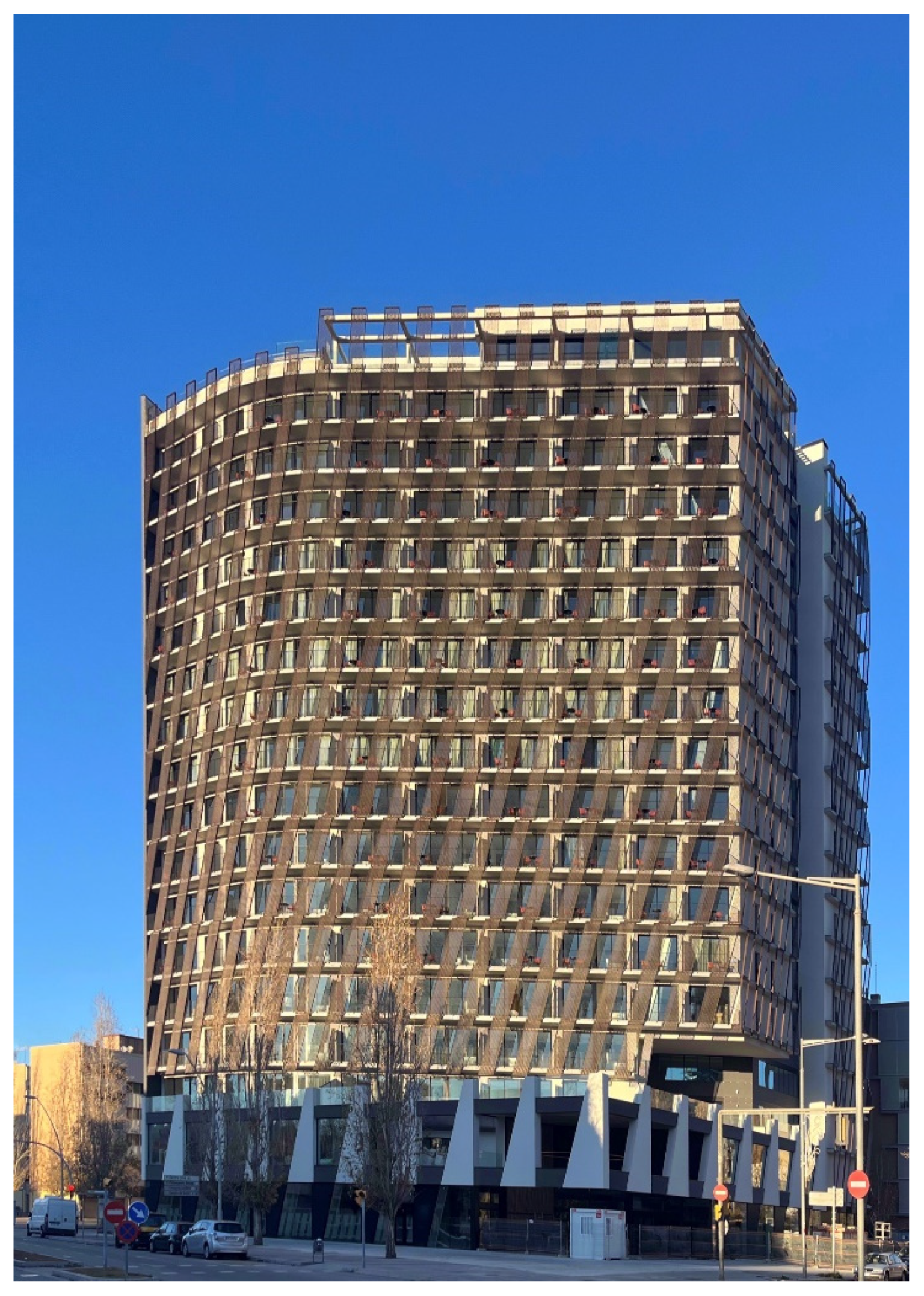
Figure 8.
Image of the hotel finished in December 2023 without the provisional prop. It can be seen that the emptying of the corner favors the resulting volumetry making it lighter. The lower diagonal of the principal frame is difficult to locate.
Figure 8.
Image of the hotel finished in December 2023 without the provisional prop. It can be seen that the emptying of the corner favors the resulting volumetry making it lighter. The lower diagonal of the principal frame is difficult to locate.
References
- Font Basté, J.; Díaz Gómez, C.; Evolució de la tipologia i sistemes constructius en edificis d’habitatges de promoció pública a l’àrea metropolitana de Barcelona 1975-1992; Universitat Politècnica de Catalunya. Departament de Tecnologia de l'Arquitectura; Barcelona 2017 Jul.
- Normativa urbanística metropolitana: normes urbanístiques; Mancomunitat de Municipis de l’Àrea Metropolitana de Barcelona; Barcelona, 2001.
- Freyssinet, E.; Guyon, F.; Rui–Wamba, J.; Fernández Alba, A.; Eugène Freyssinet, Un Ingeniero Revolucionario; Fundación Esteyco; Madrid, 2003.
- Norma de construcción sismorresistente: parte general y edificación NCSE-02, con comentarios de la Subcomisión Permanente de Normas Sismoresistentes [Real Decreto 997/2002, de 27 de septiembre]. Ministerio de Fomento; Madrid, 2003.
- UNE-EN 1991-1-4 Eurocódigo 1: Acciones En Estructuras, Parte 1-4. Acciones Generales. Acciones de Viento, Asociación Española de Normalización y Certificación; AENOR; Madrid, 2007.
- Zabara Czorna, O; Curso de oxicorte. Centro Nacional de Investigaciones Metalúrgicas; CENIM; Madrid, 1966.
- Documento Básico, Seguridad Estructural: Acciones en la edificación AE-88; Ministerio de Fomento; Madrid 1996.
- Stoller, E; Khan, Y. S.; The John Hancock Center; Princeton Architectural Press; New York, 2000.
- Buchla, D.; McLachlan, W.; Applied Electronic Instrumentation and Measurement; Merrill; New York, 1992.
- Sydenham, P. H.; Hancock, N. H.; Thorn, R. Introduction to Measurement Science and Engineering; Chichester etc: John Wiley & Sons; 1989.
- Romeral Martínez, J.L.; Balcells Sendra, J. Transductores y sensores industriales; Delegación de Alumnos ETSEIT; Terrassa, 1992.
- Riu Costa, P. J.; Rosell Ferrer, J.; Ramos Castro, J. Sistemas de instrumentación; Edicions UPC; Barcelona, 1995.
- Macchi, G. Stabilization of the Leaning Tower of Pisa. In Proceedings of the Structures Congress 2005, New York, NY, USA, 20–24 April 2005; American Society of Civil Engineers: New York, NY, USA, 2005; pp. 1–11.
- Gromysz, K. Revitalization of a Vertically Deflected Historical 16th Century Bell Tower. IOP Conf. Ser. Mater. Sci. Eng. 2019, 471, 052025. [Google Scholar] [CrossRef]
- Zhang, X.; Shan, R.; Lu, M. Rectification of Jacking Method for Brick-Wooden Buildings in Deformation Analysis with CFST Reinforcement. Struct. Des. Tall Spec. Build. 2018, 27, e1439. [Google Scholar] [CrossRef]
- A European Association for the Control of Structures joint perspective. Recent studies in civil structural control across Europe; Structural Control and Health Monitoring; 2014 Dec; 21(12):1414-36. [CrossRef]
- Gromysz, K.; Smolana, M.; Drusa, M. Research on the Characteristics of Jacks Used to Rectify Tilted Buildings. Buildings (Basel) 2024, 14, 1581. [Google Scholar] [CrossRef]
- Gromysz, K. In Situ Experimental Study on the Active Support Used for Building Rectification. Materials 2020, 13, 2015. [Google Scholar] [CrossRef] [PubMed]
- Gromysz, K. A bar model of a temporary wooden support used to remove deflections of buildings. J Phys Conf Ser 2021, 1781, 12024. [Google Scholar] [CrossRef]
- Quintero Moreno, F.; Cudós Samblancat, V. Estructuras metálicas: uniones; Universidad Nacional de Educación a Distancia (UNED); Madrid, 1988.
- Instrucción de Acero Estructural (EAE): con comentarios de los miembros de la Comisión Permanente de Estructuras de Acero. Real decreto 751/2011; Ministerio de Fomento, Boletín oficial del Estado Nº149; Madrid, 2011 jun.
- Chacon R.; Mirambell E., Real E. Influence of initial imperfections on the resistance of hybrid steel plate girders subjected to concentrated loads. Proceedings of 6th International Conference Steel and Aluminium Structures ICSAS’07. Oxford, U.K, pp. 736-743 July 2007.
- Chacon R., Mirambell E., Real E. Resistance of transversally stiffened hybrid steel plate girders subjected to concentrated loads.. Proceedings SDSS. International Colloquium on Stability and Ductility of Steel Structures, Lisbon 2006.
- Chacon, R.; Mirambell, E.; Real, E. Influence of designer-assumed initial conditions of the numerical modelling of steel plate girders subjected to patch loading. Thin Walled Structures 2009, 47, 391–402. [Google Scholar] [CrossRef]
- Chacon, R.; Guzman, F.; Mirambell, E.; Real, E.; Oñate, E. Wireless Sensor Networks for Strain Monitoring during Steel Bridges Launching. International Journal of Structural Health Monitoring 2009, 8, 195–205. [Google Scholar] [CrossRef]
- Chacon R., Mirambell E., Real E. A mechanism solution for predicting the collapse loads of girders subjected to patch loading. Proceedings of 5th European Conference on Steel and Composite Structures, Graz, Austria, pp. 159-164. September 3-5, 2008. ISBN 92-0147-00-90.
- Ansys® Academic Research Mechanical, Release 24.1, Help System, Structural Analysis Guide; ANSYS, Inc.: Canonsburg, PA, USA, 2024.
- Costales Calvo, I.; Obiol Sánchez, A.; Gómez Serrano, J.; El Pretensado en las estructuras de acero. Universitat Politècnica de Catalunya. Departament d'Estructures a l'Arquitectura; Barcelona, 2012 Sept.
- Brufau, R. Revista de obras públicas, Número 3442; Barcelona, España; 2004, 151 (3442): 67-81.
|
Disclaimer/Publisher’s Note: The statements, opinions and data contained in all publications are solely those of the individual author(s) and contributor(s) and not of MDPI and/or the editor(s). MDPI and/or the editor(s) disclaim responsibility for any injury to people or property resulting from any ideas, methods, instructions or products referred to in the content. |
© 2024 by the authors. Licensee MDPI, Basel, Switzerland. This article is an open access article distributed under the terms and conditions of the Creative Commons Attribution (CC BY) license (http://creativecommons.org/licenses/by/4.0/).

