1. Introduction
Polyvinyl chloride (PVC) is one of the most consumed commodity polymers in the world, representing around 17% of the global market. It was one of the first polymers to be discovered and is currently undergoing full evolution.[
1,
2,
3]
The advancement of electrospinning technology observed in recent decades stands out among nanofiber preparation methods due to its advantages including high control lability, simple operation, low cost, and wide adjustability.[
4] These characteristics have led to the expansion of the use of PVC for a wide variety of applications: air filtration systems[
5], water treatment, batteries, protective clothing, among others. Due to the flexibility of the electrospinning process, it is possible to obtain nanofibers with diameters ranging from a few hundred nanometers to several micrometers. Among several interesting characteristics of electrospun PVC membranes, mechanical resistance, adjustable hydrophobicity, and high porosity can be highlighted.[
6]
Although the fibers obtained by the electrospinning technique have a high surface area, high porosity and interesting electrochemical characteristics, nanofibers prepared with a single polymer often do not meet the requirements for practical applications. On the other hand, polymer nanocomposites generally exhibit multifunctional properties and have been widely used in applications in biomedicine, microwave absorption, electro chemical and optical materials.[
7] PVC is among the most used materials in the production of nanocomposites due to its characteristics already mentioned in addition to the possibility of improving its mechanical properties and high environmental resistance.[
8] The application restrictions are mainly related to its high glass transition temperature (Tg), resulting from strong polar C-Cl interactions.[
9]
The combination of PVC with other functional nanoparticles, such as carbon nano tubes (CNTs), in the electrospinning process makes it possible to expand the range of application of the material to energy, environmental and biomedical fields, among others.[
10,
11] The incorporation of carbonaceous nanofillers to the PVC matrix impacts the mobility of the polymer chains and, thus, their effect on the structure depends on a variety of factors: such as size, aspect ratio, and chemical functionalization.[
12] With the addition of CNTs to the PVC matrix, some effects can be observed, such as changes in Tg and Tp (simultaneous flow temperature), due to the physical interaction between the CNTs and the polymer molecules, and the presence of an interphase between the matrix and the surface of the nanotubes. This new phase presents different properties in relation to neat PVC, promoting molecular mobility restrictions.[
13] For a well dispersed system, a small amount of nanotubes provides a large interfacial area, promoting changes in the mechanical, electrical and thermal properties of the polymer.[
14,
15]
The electrospinning of PVC membranes has been recently reviewed by Phan et al.,[
2] showing the huge potential of composite PVC nanomembranes. For instance, Namsaeng et al.,[
16] observed an increase of 127% and 175% in tensile strength and Young's modulus, respectively, in electrospun PAN/PVC mats, evidencing a welding effect, and 205% and 314%, respectively, with the addition of 1% by weight of MWCNTs. In another work with the addition of nanotubes, Elkasaby et al.[
17] evaluated noise absorption in electrospun PVC membranes, observing that the addition of 5 wt.% CNTs improved sound absorption by 62% compared to the unfilled material, reaching a maximum value of the absorption coefficient of 0.4 at 800 Hz. Significant improvements in corrosion resistance in the 6061T6 aluminum alloy with the use of electrospun PVC/ZnO nanofibers as a coating have been also reported.[
18]
Regarding electrical properties, Yang et al.[
19] reported that the addition of 0.05 wt% CNT to electrospun polyvinylidene fluoride (PVDF) nanofiber membranes provided highly sensitive flexible capacitive sensors. Sakamoto et al.[
8] established a method to align CNTs on a substrate via an electrospinning process with the aim of maximizing the intrinsic conductive and structural properties of CNTs. To this end, PEVA/CNT nanofibers were electrospun on an aluminum substrate and further heated in air up to 400 °C to leave only the CNTs on the substrates. Impedance measurements showed that the charge transfer resistance was reduced from 20Ω to 8Ω with the alignment of the CNTs. In another recent review, Wang et al.[
9] emphasized that the electrochemical performance of fibers is largely determined by their structure, which is dependent on the parameters of the electrospinning process. The advantages of controllability in fiber morphology are highlighted, mentioning oriented, hollow, and porous fiber structures, which can improve the ion transport efficiency, promote intrinsic conductivity, and offer greater specific surface areas, providing a significant improve on electrochemical performance.
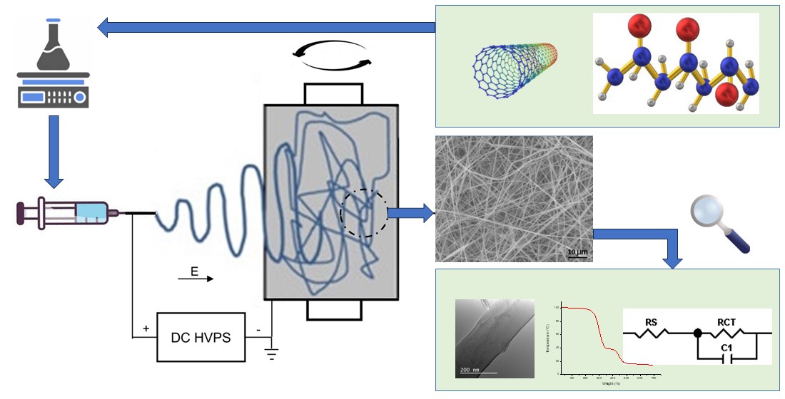
However, no reference to the effect of nanotube addition to the electrical properties of electrospun PVC membranes have been reported so far. Thus, the present study aims to evaluate the influence of CNTs addition and encapsulation in thermal and electrical behavior of electrospun PVC membranes, by morphological thermal characterization and electrical impedance spectroscopy.
2. Materials and Methods
2.1. Materials
Homopolymer PVC (NORVIC® SP 750RA), obtained by suspension polymerization, was supplied by Braskem (Brazil). Multi-walled carbon nanotubes (MWCNTs) were purchased from Chengdu Organic Chemicals Co. Ltd. (China), batch TNIM4, with 95% puri-ty. According to the manufacturer's information, MWCNTs have an external diameter of 10-30 nm, an internal diameter of 5-10 nm and a length of 10-30 μm.
Tetrahydrofuran (THF) and dimethylformamide (DMF), both supplied by Dinâmica (Brazil) with a minimum content of 99 and 99.8%, respectively, were used as solvents. Triton-X100, supplied by Vetec Química (Brazil), was used as a surfactant.
2.2. Solution Preparation
PVC solutions were prepared in THF/DMF 50/50 at a concentration of 18 wt.% con-taining amounts of 0%, 1%, 2% and 3% by weight of CNT. The detailed quantities of each component in the solutions are presented in
Table 1.
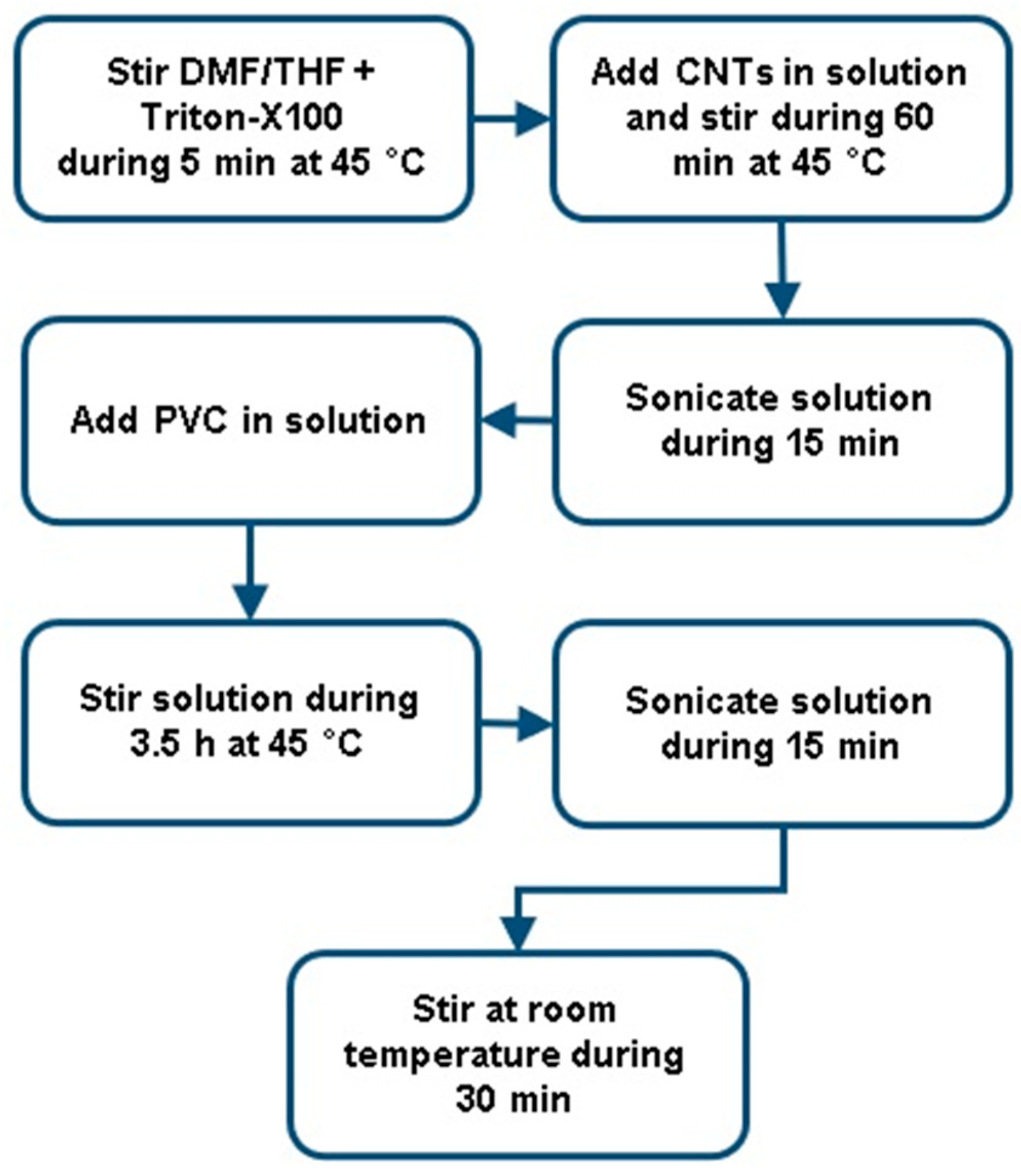
To produce the PVC/CNT solutions presented in
Table 1, the 7 steps contained in
Figure 1 were followed.
2.3. Preparation of Electrospun Membranes
To produce the PVC/CNT electrospun membranes, an Eletrotech Lab EF 2B CRT 0212
electrospinning equipment, produced by DBM Eletrotech (Brazil), was used. The equipment has a rotating collector made of Ø60x200 mm aluminum, a high voltage source for up to 20 kV and two infusion pumps.
Table 2 presents the settings used to produce the membranes.
2.4. Thermal Characterization
Thermogravimetry (TG) was carried out in a TA Instruments Thermogravimetric Analyzer model TGA55. The heating rate was 10°C/minute, in a temperature range from 25 to 700°C, under N2 atmosphere. The samples had ca. 5 mg.
Differential Scanning Calorimetry (DSC) analyses were carried out in a NETZSCH DSC 200F3 equipment; the specimens had ca. 5 mg. The analyzes were run with heating and cooling rates of 10°C/min, under N2 atmosphere, gas flow of 40 ml/min and a closed panel system.
To obtain the first heating curves, the samples were heated from 25°C to 165°C, remaining at that temperature for 1 min. For the second heating, the material was cooled to 25°C and subsequently heated again to 165°C, remaining at that temperature for 1 min.
2.5. Morphological Characterization
Field-Emission Scanning Electron Microscopy (FESEM) was performed in a JEOL JSM-6701F operated at 10 kV. The samples were metallized with gold (Dentan Vacuum Desk V) prior to the analyses.
Transmission electron microscopy (TEM) images have been obtained with a JEOL model JEM 2100 microscope. Samples were directly electrospun on carbon sample holders with 300 mesh copper grids (CF300-Cu).
2.6. Electrical Impedance Spectroscopy (EIS)
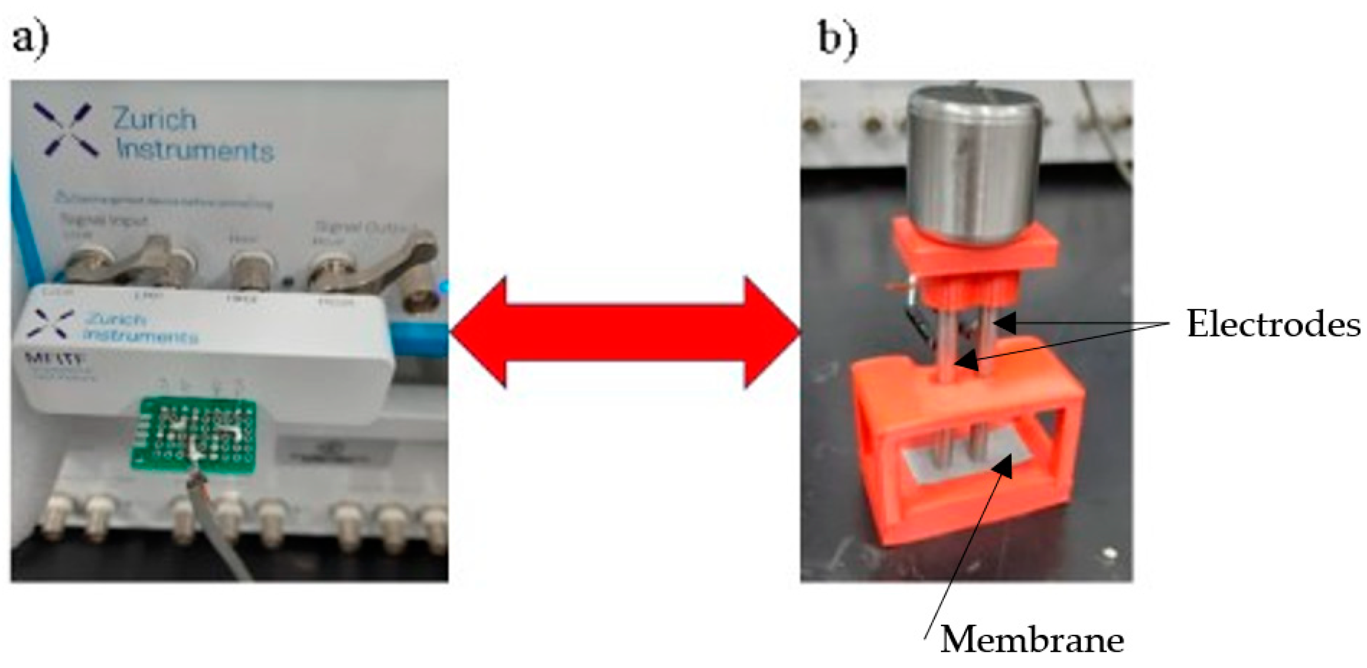
For the EIS analyses, a MFIA equipment (Zurich Instruments) was used in the frequency range between 10 Hz and 5 MHz, at 300mV and current of 10mA. The measurements were carried out using 2 electrodes made of Ø3/16”x60 mm stainless steel with polished ground contact surfaces, at a distance of 5 mm between the electrodes. Five measurements were taken on each of the samples in the longitudinal direction in the orientation of the mem-brane production. The membranes analyzed were between 150 and 160 μm thick.
Figure 2 shows the device used in the measurements. To simulate the results, the Zview software version 2.8d was used.
3. Results and Discussion
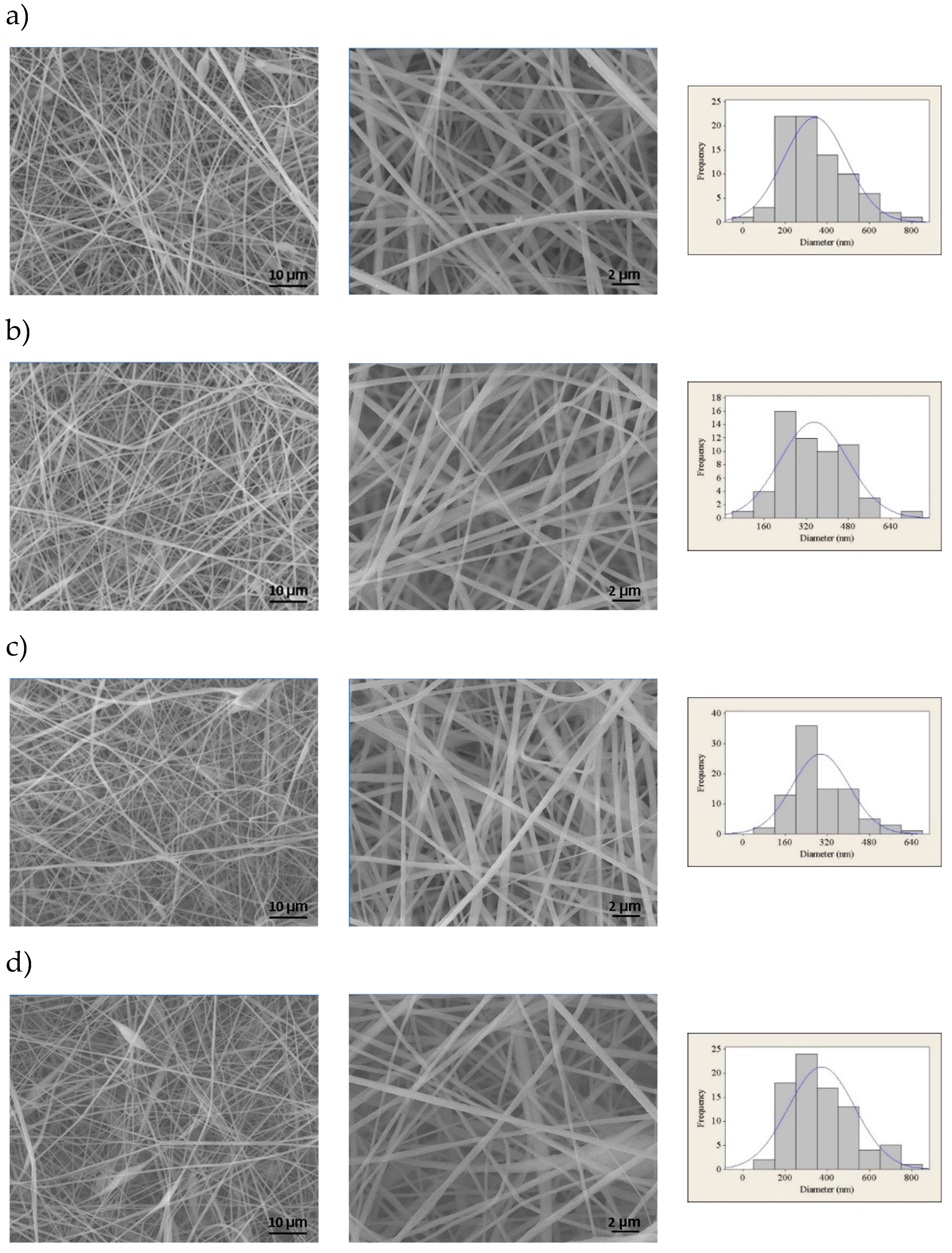
Figure 3 shows the FESEM images and fiber size distribution histograms of PVC electrospun membranes with different CNT concentrations.
It is observed that the membranes are composed of relatively uniform fibers containing few beads and flaws, except for the membrane containing 3 wt% CNTs, in which there is a greater presence of beads next to the fibers. It has been probably caused by the formation of CNT clusters in the solution, as also observed by Mazinani and Dubois for PET/CNT electrospun membranes.[
20] The fibers presented average diameters from 295 to 373 nm, with significant differences only between the compositions containing 1 and 2 wt%, and between 2 and 3 wt%, for a significance of 95% considering the Mann-Whitney non-parametric hypothesis test.
Even though the increase in the concentration of CNTs in the solution can promote greater conductivity and a greater number of inductive charges, this did not result in a re-duction in the average diameter of the fibers. It is thus suggested that the concentration of CNTs was not sufficient for percolation to occur. The results are similar to those reported by Pham and Uspenskaya, who evaluated the influence of processing variables on the diameter of PVC nanofibers electrospun from 15 wt.% solutions at a flow rate of 1mL/h.[
21]
Still regarding fiber diameter, no tendency towards reduction in fiber diameter was found due to the increase in the concentration of CNTs in the PVC matrix, unlike what was observed by Sharafkhani and Kokabi in electrospun PVDF/MWCNT fibers.[
11] El Messiry and Fadel also observed a gradual reduction in the average fiber diameter when they increased the cellulose acetate (CA) concentration from 2% to 8% in PVC/CA bi-component nanofibers.[
12] The addition of other nanoparticles to PVC, such as Fe, Fe
3O
4, Al, steel and brass, and have also caused a decrease in the fiber diameters.[
13,
14]
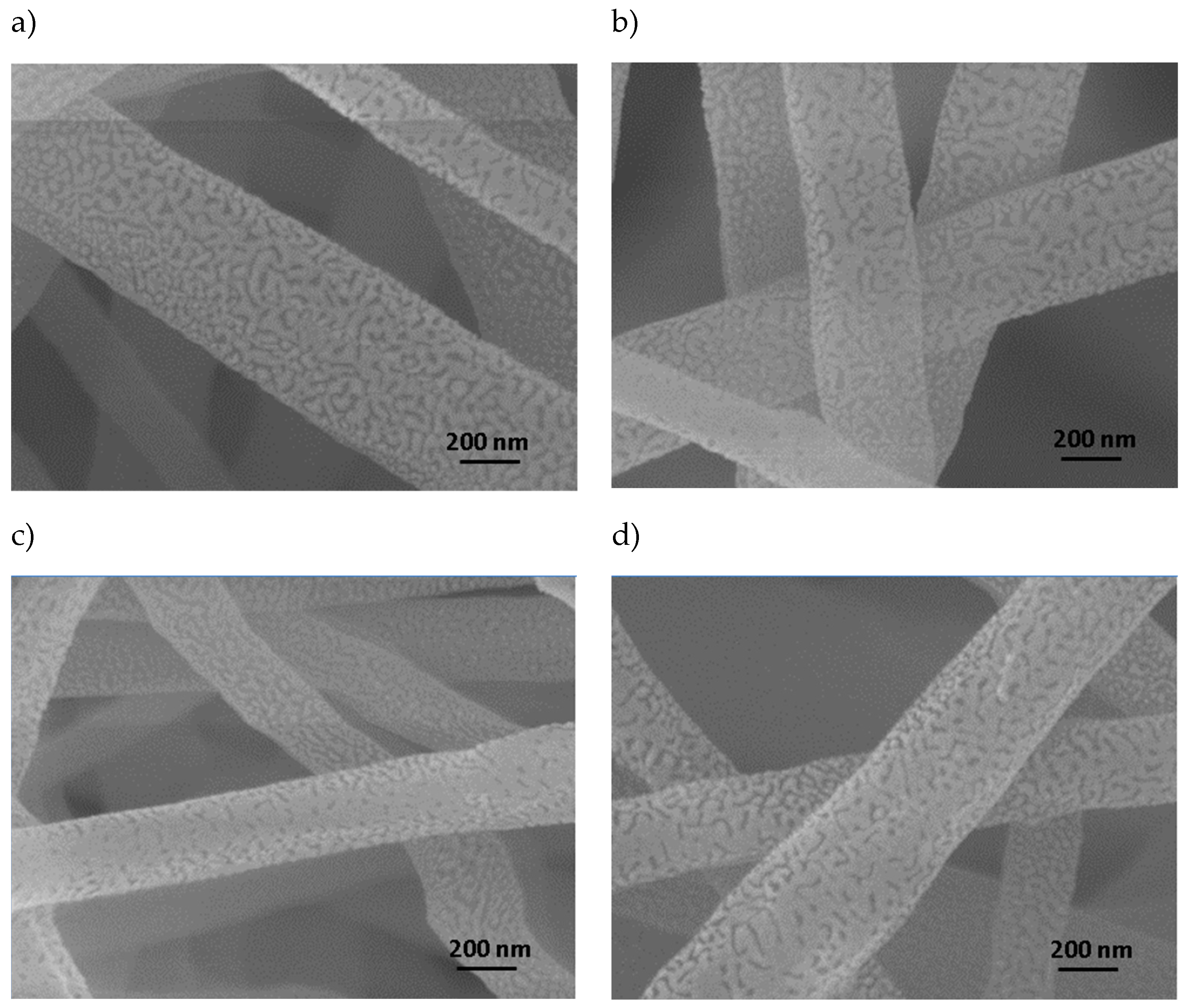
Figure 4 shows images demonstrating the surface roughness present in PVC/CNT fibers. It can be also noted that the roughness is independent of the CNT concentration.
There are no studies in the literature reporting the surface morphology of PVC electrospun fibers obtained from THF/DMF solutions, but it is suggested that the formation of the rough structure presented on the surface of PVC/CNT fibers may be related to the mechanism described in the work of Lin et. al., where it was proposed that as the molecular weight of PS diluted in THF/DMF is decreased, the entanglement of the polymer chains of the polymer is reduced, accelerating the evaporation and diffusion of the solvent.[
22] This will result in the rapid separation of phases on the surface, generating surface roughness. The authors observed in the study that, when PS was diluted with pure THF, pores were formed on the surface, instead of grooves or wrinkles, as a result of the rapid evaporation of the solvent. With the increase in the percentage of DMF in the solution, grooves were formed, causing a rough surface. The different surface morphologies of these fibers can be attributed to the competition between the rapid phase separation and solidification resulting from the mutual diffusion of the solvent within the jet and the sur-rounding moisture due to the different solvent compositions used in the process. TEM images presenting the dispersion of CNTs inside electrospun PVC fibers are shown in
Figure 5.
It is observed a good adhesion between the CNTs and the polymer matrix, with only few regions presenting agglomerates. Most of the nanotubes are located inside the fibers and oriented along them, i.e., encapsulated, and only a small portion is positioned on the external side of the fibers. The CNTs that are not fully encapsulated in the PVC fibers are due to their non-uniformity, presenting folds, favoring mechanical entanglement.[
23]
As observed in the work of Sharafkhani and Kokabi,[
11] who studied electrospun PVDF/MWCNT membranes for piezoelectric applications, as the diameter of the fibers is reduced, the better the alignment of the nanotubes with the fibers, and irregularities in the coaxial alignment are reduced. The reduction in fiber diameter prevents the random positioning of CNTs, making it difficult to form agglomerates. Therefore, it is essential to use an adequate concentration of CNTs. The high concentration tends to favor the formation of agglomerated regions, compromising the final properties of the composite. The results are also in line with Aliahmad et al.,[
24] who observed a unidirectional alignment of the CNTs inside the fibers due to the presence of an electric field acting on the nanotubes. This formation is suitable for many applications, covering sensors, reinforcements, and membranes.
Dror et al. proposed a theoretical model to explain the behavior of particles such as CNTs during the electrospinning process. Initially the CNTs are randomly oriented, but due to the wedge-shaped flow they are gradually oriented mostly along the streamlines so that the straight CNTs are oriented as they enter the Taylor cone.[
25] It is suggested that combined with the wedge-shaped flow, the alignment of the CNTs is also favored by the action of the electric field, where, according to Yan et al., the intensity of the electric field, the exposure time, the concentration of the nanofiller and the viscosity of the solution are decisive.[
23]
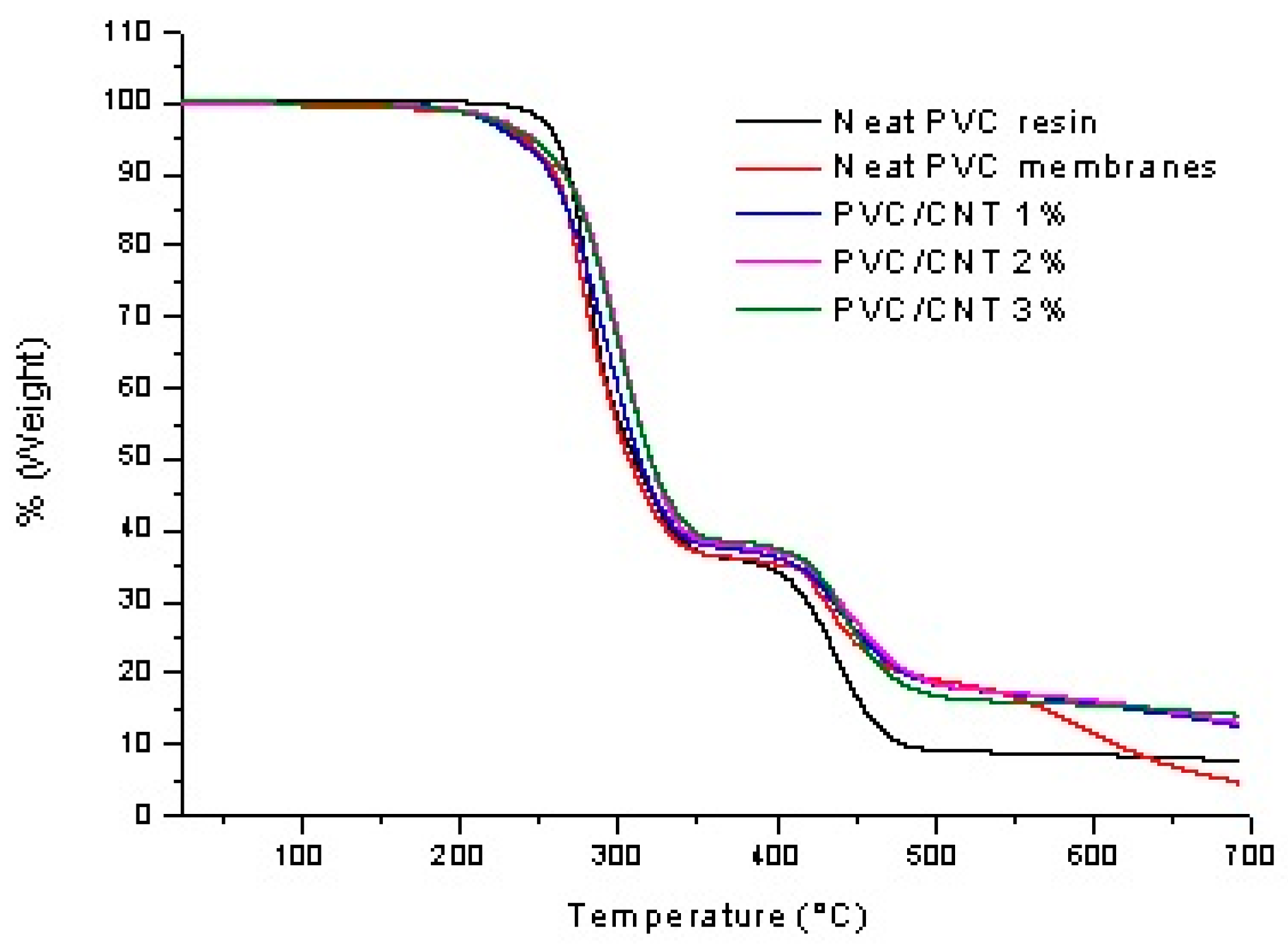
The thermal mass loss behavior of the PVC/CNT electrospun membranes, as well as the neat PVC resin, are shown in
Figure 6.
A small mass loss is observed below 150°C in the PVC/CNT membranes, which can be attributed to the vaporization of THF and DMF that were retained in the PVC matrix after electrospinning. Both PVC/CNT nanocomposites and resin present two stages of degradation. In the first stage, attributed to the PVC dehydrochlorination reaction, a mass loss of 64% is observed for the resin and 62% for the fibers containing 3% CNTs, where the mass loss begins shortly after 200°C. For the other PVC/CNT compositions, the mass loss was intermediate between the two values. In the second stage, a mass loss of 17% and 11% is observed for the resin and the nanocomposite, respectively, where the mass loss begins at around 400°C, being attributed to the rupture of the double bonds of the polyene structure, forming volatile hydrocarbons in addition to solid char residue. From 550°C on-wards, variations in the TG curves are observed, which can be attributed to the different concentrations of CNTs in the structure. Analyzing the results, the presence of CNTs in the composition provides, in general, an increase in the thermal stability of the composite. The TG curves are also similar to those found in the study by Hasan et. al., where the authors also evaluated PVC/CNT fibers.[
26]
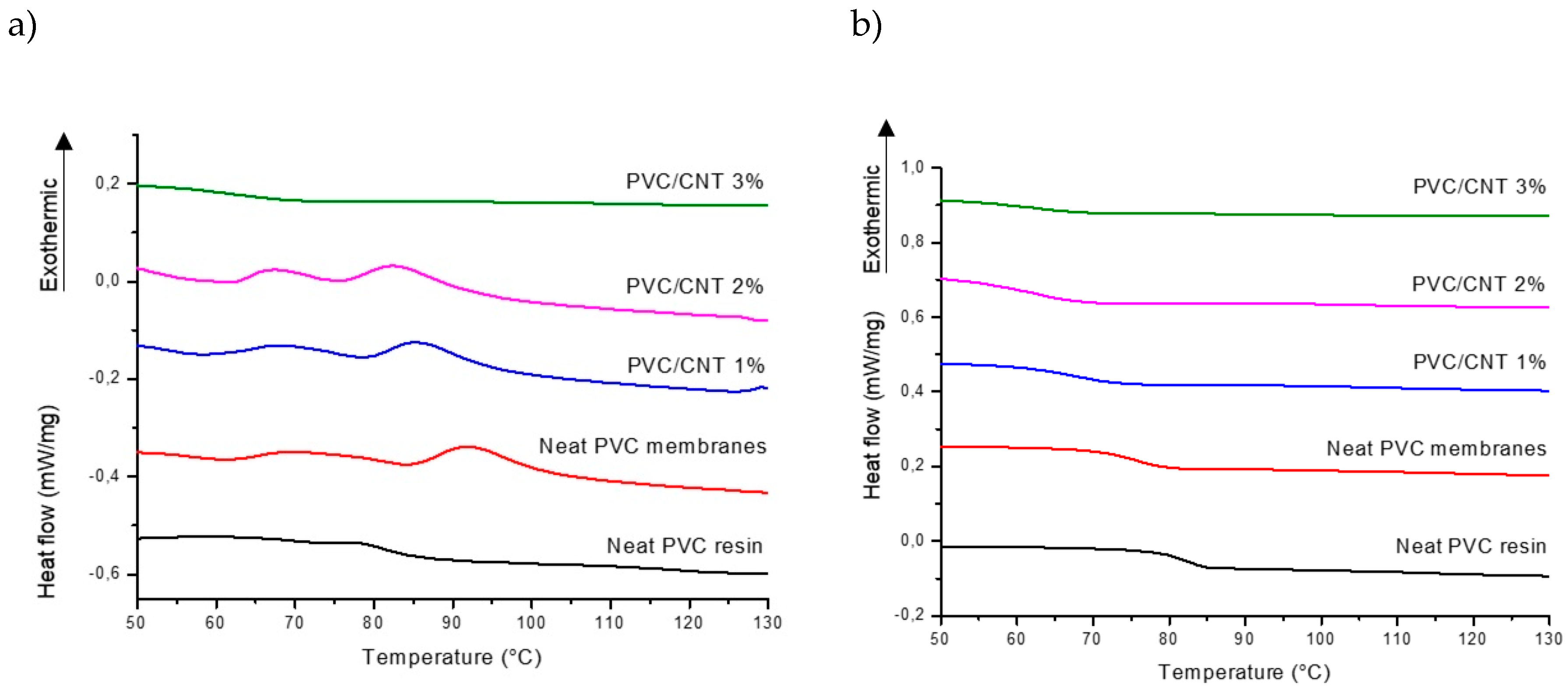
Figure 7 shows the DSC curves for the first and second heating of PVC/CNT mem-branes and the neat PVC resin.
The results show a well defined trend in the reduction of the glass transition temper-ature (Tg) as the concentration of CNTs in the composite increases.
Table 3 presents the detailed results.
The variation in the Tg is strongly related to the mobility of the PVC polymer chains, which can be influenced by the molecular mass, tacticity and the interaction of the nanotubes and the matrix.[
27] Nevertheless, the results obtained are contrary to various studies reviewed by Tomaszewska et al.[
27] where the addition of CNTs to PVC matrices provides an increase in Tg, by reducing the mobility of the polymer chains. It is suggested that it may be associated with the saturation limit and dispersion of nanotubes in the matrix, causing a plasticizing effect on the composite. The presence of agglomerates at high concentrations of CNTs may also have relatively poor interfacial interactions with the matrix.
It is also worth noting that, in the first heating (
Figure 6a), just above Tg, an endo-thermic hysteresis peak is observed, characteristic of volume relaxation due to the rapid formation of the fiber structure during the electrospinning process, as observed by Ero-Phillips et al.[
28] and Bognitzki et al.[
29] for PLLA fibers.
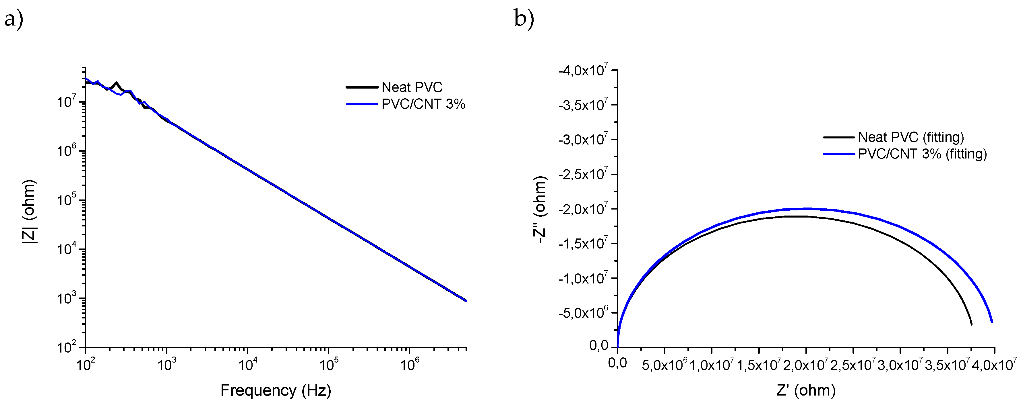
Figure 8 presents the results of electrical impedance spectroscopy of pure PVC and 3% PVC/CNT electrospun blankets. Analyzing the results of |Z| (
Figure 8a), no significant differences were found between the two samples considering the non parametric Mann-Whitney test for a significance of 95%.
In
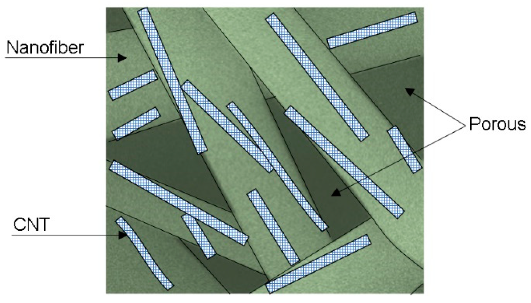
Figure 8b, the fitting and experimental Nyquist plots for PVC and PVC/CNT 3% membranes, where it is possible to observe a charge transfer resistance of 38 Mohm and 40 Mohm, respectively, for pure PVC and PVC/CNT 3%. The results confirm the resistive characteristic of the material regardless of the presence of CNTs in the structure. I.e., the addition of 3 wt.% CNTs did not interfere with the impedance spectroscopy results. It is suggested that the reason for non-percolation was basically due to two factors: the first is the encapsulation of the vast majority of CNTs within the fibers and the second is the high porosity of the membranes caused by the spaces (voids) between the fibers.
Figure 9 proposes to schematically illustrate the CNTs encapsulated inside the fibers and the presence of pores or spaces between them.
Thus, although the high electrical conductivity of CNTs, the PVC/CNT 3% membrane, in the dry state, presented almost the same electrical behavior as the insulating porous PVC matrix, as there was no formation of a conducting network due to the encapsulation of the nanotubes within the fibers. The pores, within and between the fibers, also play an important role in determining the physical and chemical properties of electrospun membranes.[
30]
4. Conclusions
The study aimed to evaluate the influence of CNTs addition in thermal, morphological and impedance spectroscopy. It was observed that the addition of nanotubes did not affect the average diameter of the fibers, as well as their surface morphology. However, most of the CNTs were located inside the fibers (‘encapsulated’) and longitudinally oriented, and just a small part of the nanotubes was positioned externally.
It can be also highlighted a significant decrease (up to 20 °C) for the PVC/CNT com-posite membranes, in comparison to neat PVC, which is possibly related to the ‘saturation limit’ of CNTs in PVC, leading to clusters, and hindering the dispersion of the nanofiller.
Regarding the results of electrical impedance spectroscopy, no significant differences were found due to the presence of CNTs in the PVC membranes, in the dry state. It is sug-gested that high charge transfer resistance is related to the high porosity and encapsulation of CNTs in the fibers, which prevents the formation of a percolation network throughout the insulating matrix.
