1. Introduction
Helical carbon fiber possesses distinctive mechanical [
1] and electrical [
2] properties, which can be used in wave absorbing materials [
3], hydrogen storage materials[
4], electrode materials[
5], reinforced composite materials[
6] and so on. Consequently, it exhibits a vast range of potential applications. However, the helical carbon fiber is faced with the problems of low output, difficult mass preparation and high price. Therefore, it is important to clarify the formation mechanism of helical carbon fiber and develop the growth method of helical carbon fiber with high yield. Helical carbon fiber was first obtained in 1953 by using iron oxide as a catalyst to crack carbon monoxide [
7]. Baker [
8] et al. chose to use acetylene as a carbon source and successfully prepared carbon fiber with helical structure using alloy catalyst. Motojima [
9] et al. used chemical vapor deposition, using Ni powder as a catalyst and acetylene as a carbon source to prepare regular double helical carbon fibers at temperatures between 350 and 750℃.The preparation methods and growth conditions of helical carbon fibers have been consistently updated and refined since then.In this study, we present a simplified approach to achieve the growth conditions necessary for the synthesis of helical carbon fibers. By utilizing anhydrous ethanol as the carbon source and iron wire as the growth substrate, we successfully fabricated a helical carbon fiber skeleton formed by a large number of helical carbon fibers hooking with each other.
2. Materials and Methods
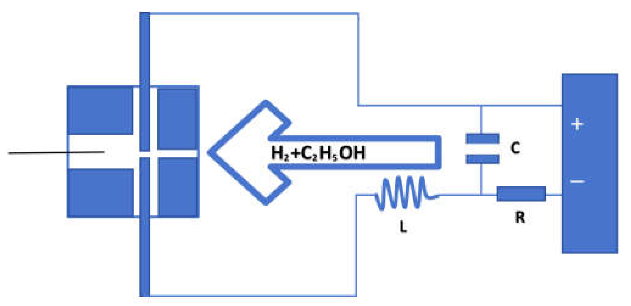
Using the arc glow discharge device as shown in the
Figure 1 [
10], graphite is selected as the growth cavity,iron wire is selected as the substrate, arc glow discharge is carried out between two tungsten needle electrodes, and the mixed gas of ethanol and hydrogen passes through the discharge area, becomes activated particles, and then is sprayed onto the wire substrate to realize the growth of helical carbon fiber.
The experimental parameters encompass a capacitance of 270pF, an inductance of 0.4mH, a current limiting resistance of 150Ω, a voltage of 550V, and the discharge power is determined using the subsequent formula:
In the experiment, the control currents were set at 2.3A, 2.4A, 2.5A, 2.7A, and 2.9A respectively, resulting in corresponding power outputs of 483W, 468W, 450W, 405W and 348W.
The experiment was preheated for a duration of 10 minutes, followed by a growth period of 30 minutes on the wire substrate. The black sample was found to be almost full of growth holes with a diameter of 10mm.
Replace the substrate material: replacing the iron wire substrate with Fe-Cr-Al wire and tungsten needle. Under identical growth conditions, no discernible growth marks were observed on samples grown using Fe-Cr-Al wire and tungsten needle.
3. Results
3.1. Materials Characterization
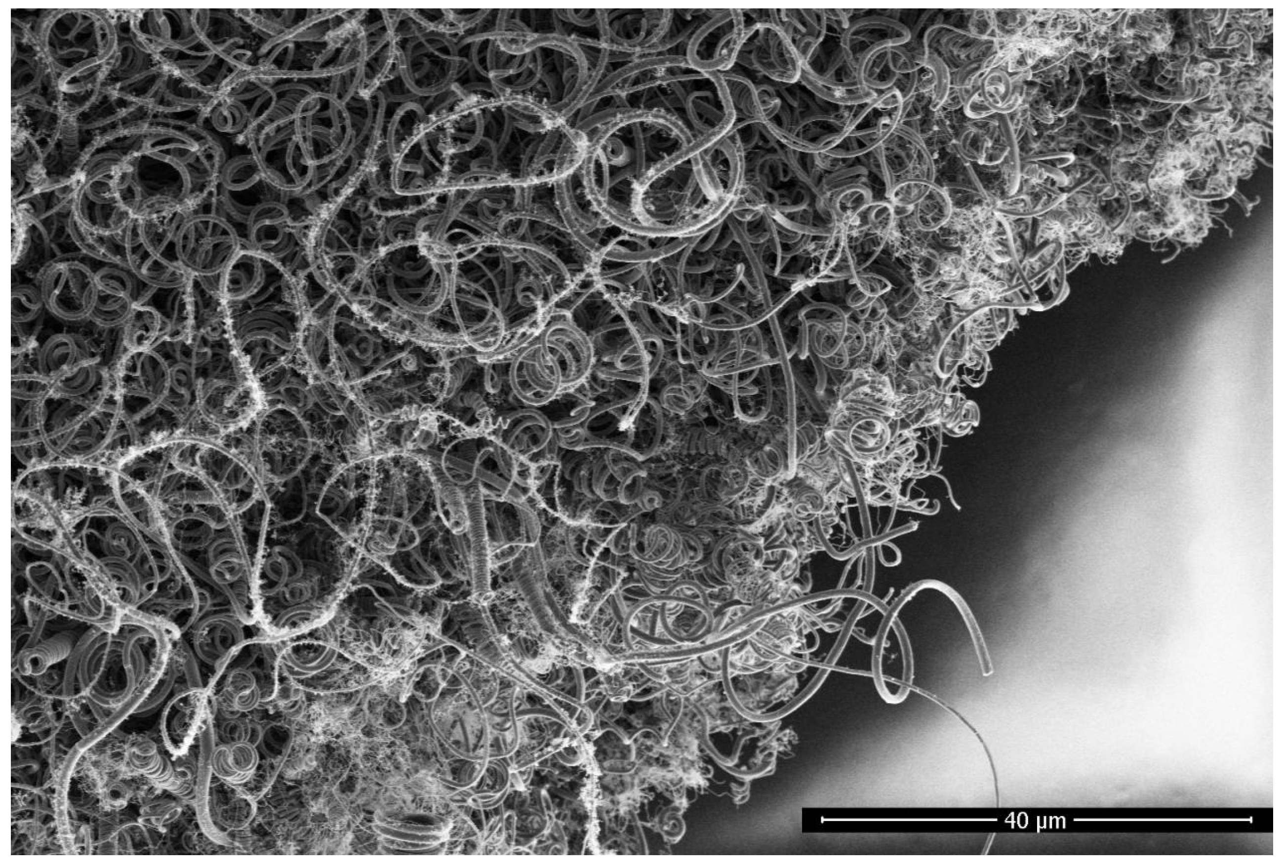
A Magellan 400 field emission scanning electron microscope was used to scan samples obtained on an iron wire substrate using the arc glow discharge method. The growth current of the sample is 2.5A.As shown in
Figure 2, the sample is found to be a carbon fiber with a helical structure, and the diameter of the helical carbon fiber ranges from 0.3μm to 1.1μm. Additionally, tiny carbon fibers much smaller than 0.3μm were also observed on the side wall of the carbon fibers.
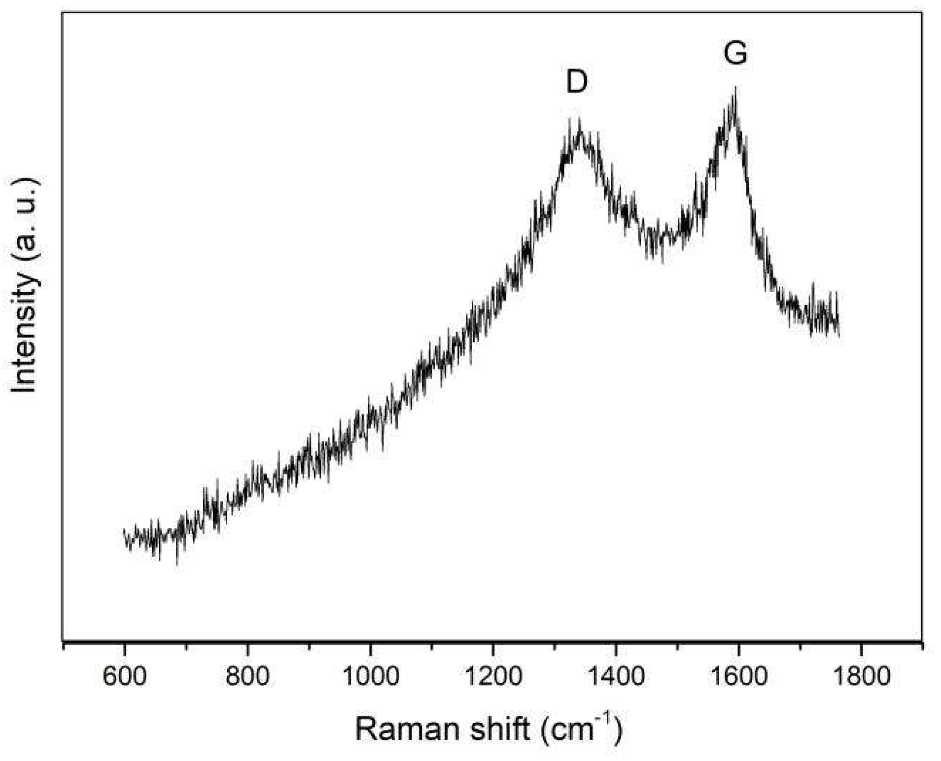
The Raman diagram of the helical carbon fiber is shown in
Figure 3, with an excitation wavelength of 532nm. D peak around 1340 cm
-1 and G peak around 1591 cm
-1 are two characteristic peaks for graphite materials. G peak represents the stretch vibration of C-C bonds in sp
2 structure, and D peak corresponds to the breath vibration mode of hexatomic rings which appears when defects exist. The intensities of the D peak and G peak are similar, indicating the presence of numerous defects in the helical carbon fiber.
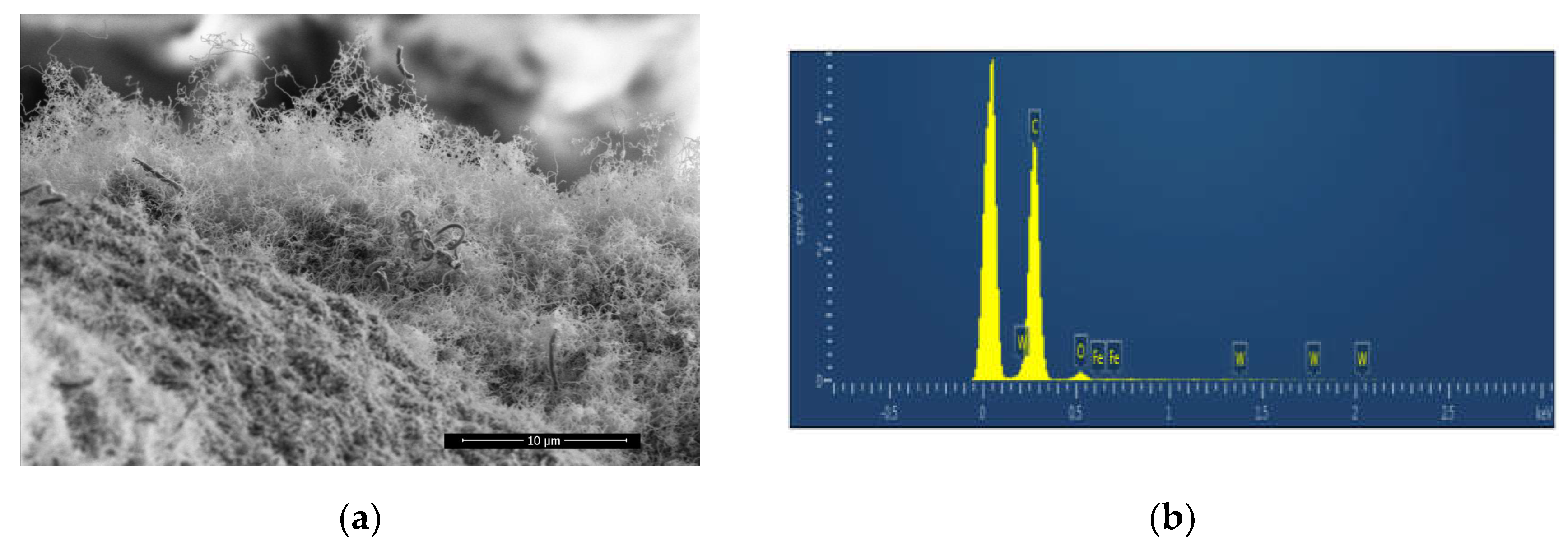
As shown in
Figure 4a, the helical carbon fiber in the sample is covered by tiny carbon fiber wraps.Area scanning was performed to obtain the Energy Dispersive Spectrum of the sample.The presence of C and O peaks was observed in
Figure 4b, while Fe and W peaks were absent, indicating the absence of both Fe and W in the sample. This suggests that there is no diffusion of iron wire substrate into the carbon fiber sample, and the tungsten needle electrode is not sprayed onto the sample.
3.2. Helical Carbon Fiber
3.2.1. Longitudinal Growth Splitting Mode
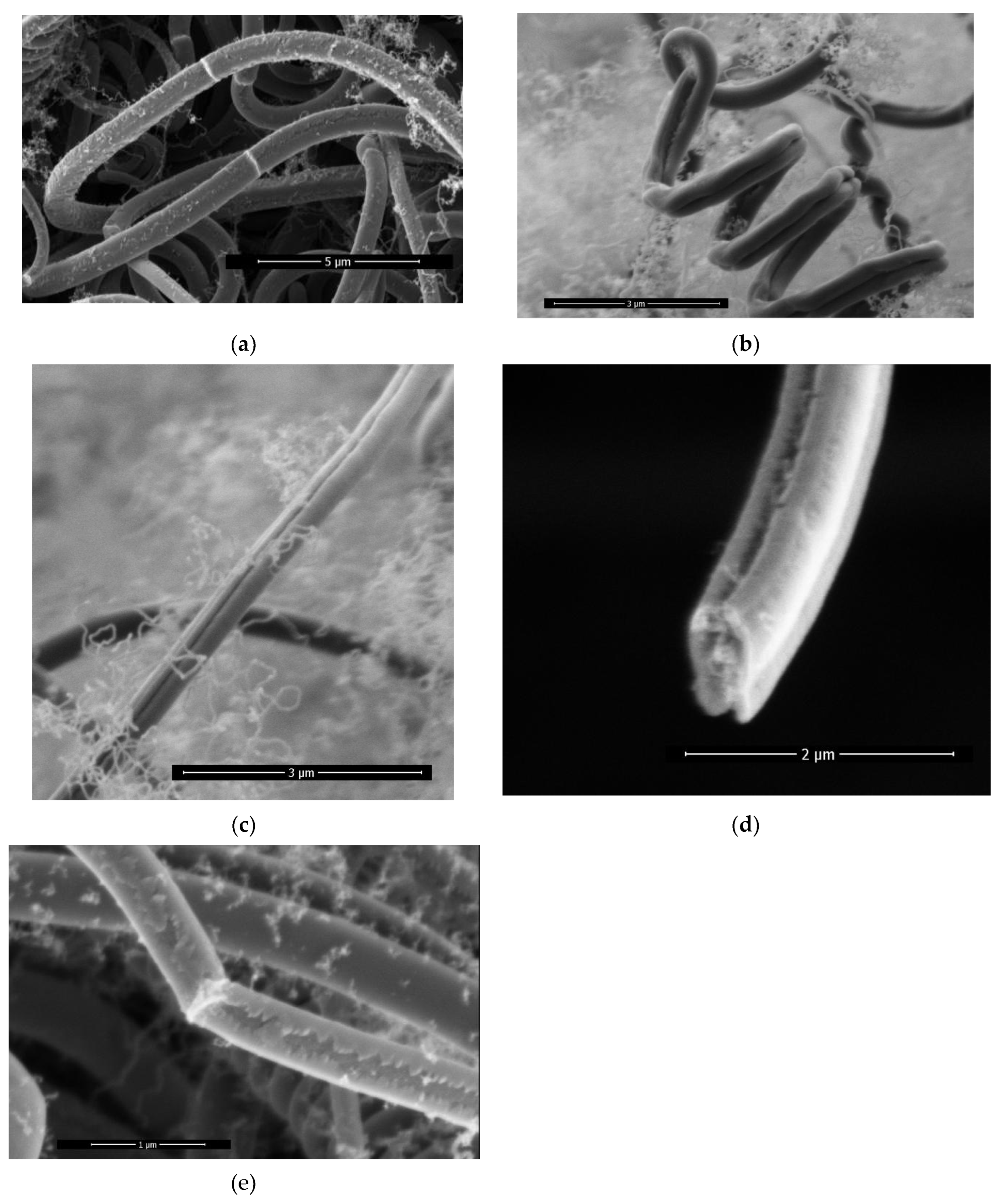
Upon observation of the helical carbon fiber samples, it was discovered that the carbon fibers exhibit three distinct structural types: single-wire, double-wire, and a transitional line structure featuring with an intermediate dent .
Figure 5a shows a partial photo of a carbon fiber sample grown at a current of 2.5A. The surface of the two single-wire carbon fibers in the middle is smooth and uniform in diameter, showing an obvious single-wire structure.
The diagram in
Figure 5b represents the sample under current condition 2.3A, the carbon fibers that make up this helical structure have significant intermediate dents in the middle, so we believe it is a double-wire helical structure.Double-wire opening occurs at the end of the double-wire helical carbon fiber. The two carbon fibers grow in different directions.
Figure 5c shows a carbon fiber with an intermediate dent , however, since the dent is not deep enough to split into two single-wire carbon fibers, it is identified as a transitional line form of carbon fiber.
Figure 5d shows the cross section of the carbon fiber of the transition line, where both the upper and lower sides of the dent marks can be observed.
The single-wire carbon fiber, as shown in
Figure 5e, exhibits a very shallow intermediate dent on the surface. We believe this indicates the initial stages of carbon fiber transformation.
There is a longitudinal growth splitting mode of carbon fiber, single-wire carbon fiber will evolve intermediate dents in the process of longitudinal growth, and as the degree of dents deepens, it will become synchronous growth of double-wire carbon fiber. Under certain conditions, the double-wire carbon fiber opens the double-wire structure and completes the splitting phenomenon from one carbon fiber to two carbon fibers.
3.2.2. Secondary Nucleation Growth
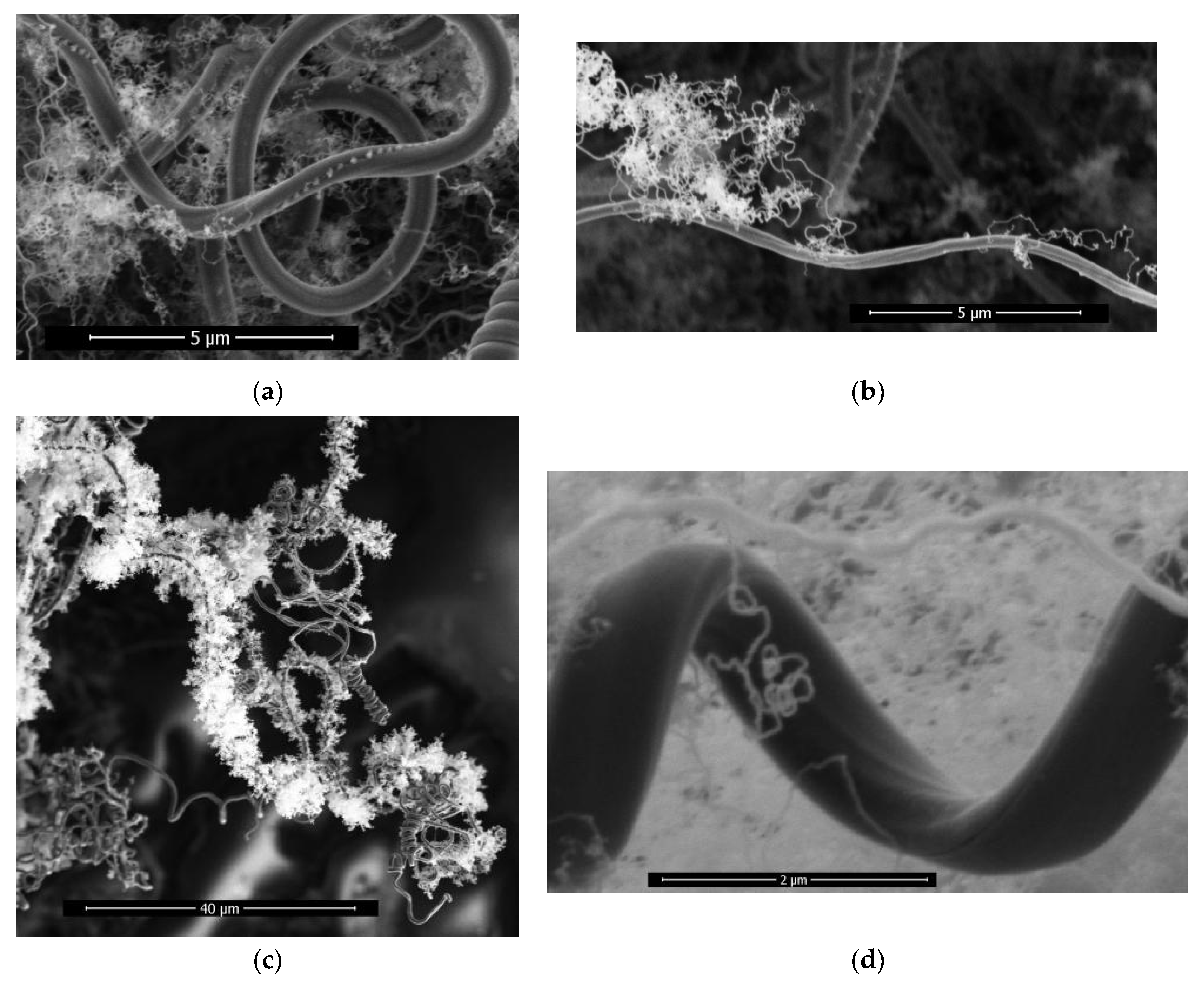
As shown in
Figure 6a, the growth current condition of the sample is 2.3A, and it is observed that nuclei are arranged in the intermediate dent of the transition line structure.In
Figure 6b, a small number of tiny carbon fibers grow on the side wall of a single carbon fiber.In
Figure 6c, the side walls of a single carbon fiber are completely covered by tiny carbon fibers.
The helical carbon fiber can be observed as a result of secondary nucleation growth, involving two distinct stages of nucleation and linear growth. Furthermore, it demonstrates the excellent suitability of carbon fiber as a self-nucleation substrate.This phenomenon of the growth of tiny carbon fibers in the side wall nucleation of carbon fibers is called the secondary nucleation growth phenomenon of carbon fibers.
The diameter of the tiny carbon fiber obtained by secondary nucleation growth is much smaller than that of the substrate carbon fiber, as shown in
Figure 6d, which is about 0.8μm in diameter of the substrate carbon fiber and 0.03μm in diameter of the secondary nucleation growth carbon fiber.
The tiny carbon fiber obtained by secondary nucleation growth on the side wall of the carbon fiber can occupy the void as much as possible in the limited space, increasing the surface area of the carbon fiber per unit volume.
3.2.3. Change-Direction Ring
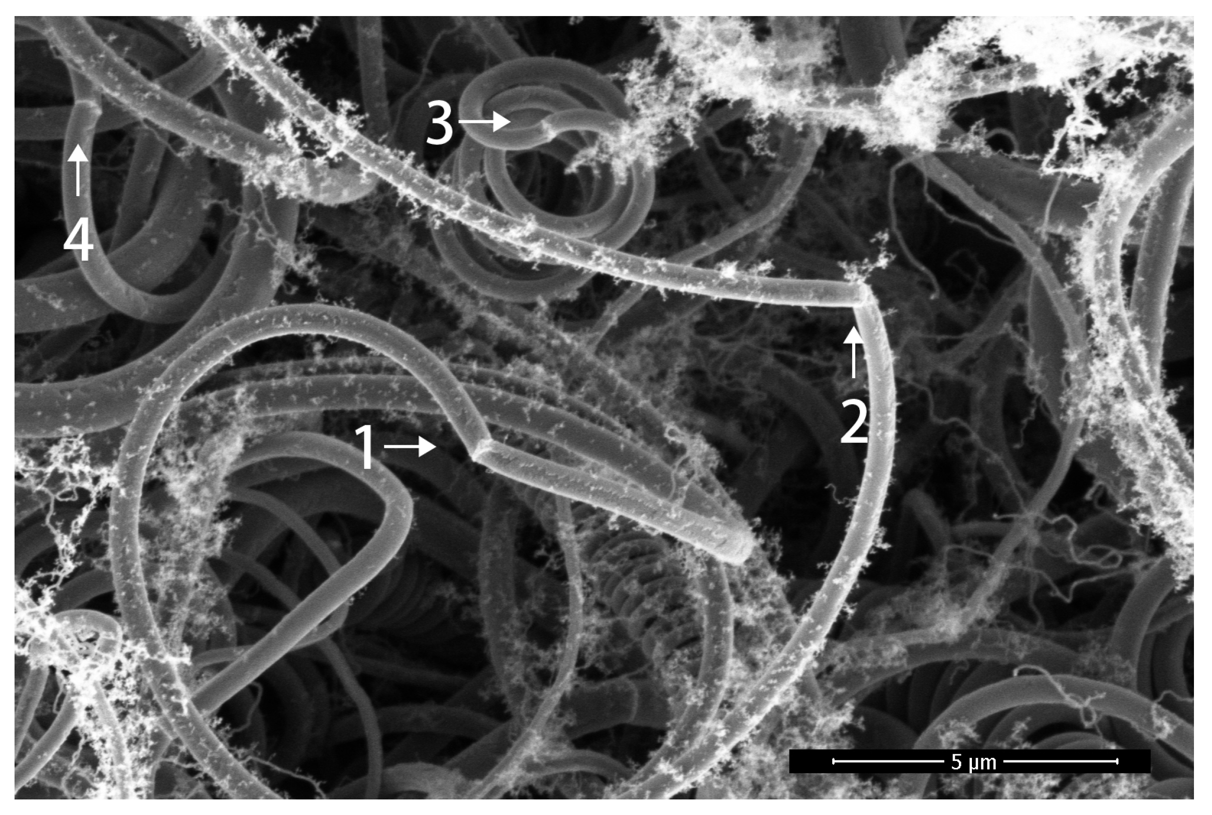
As shown in
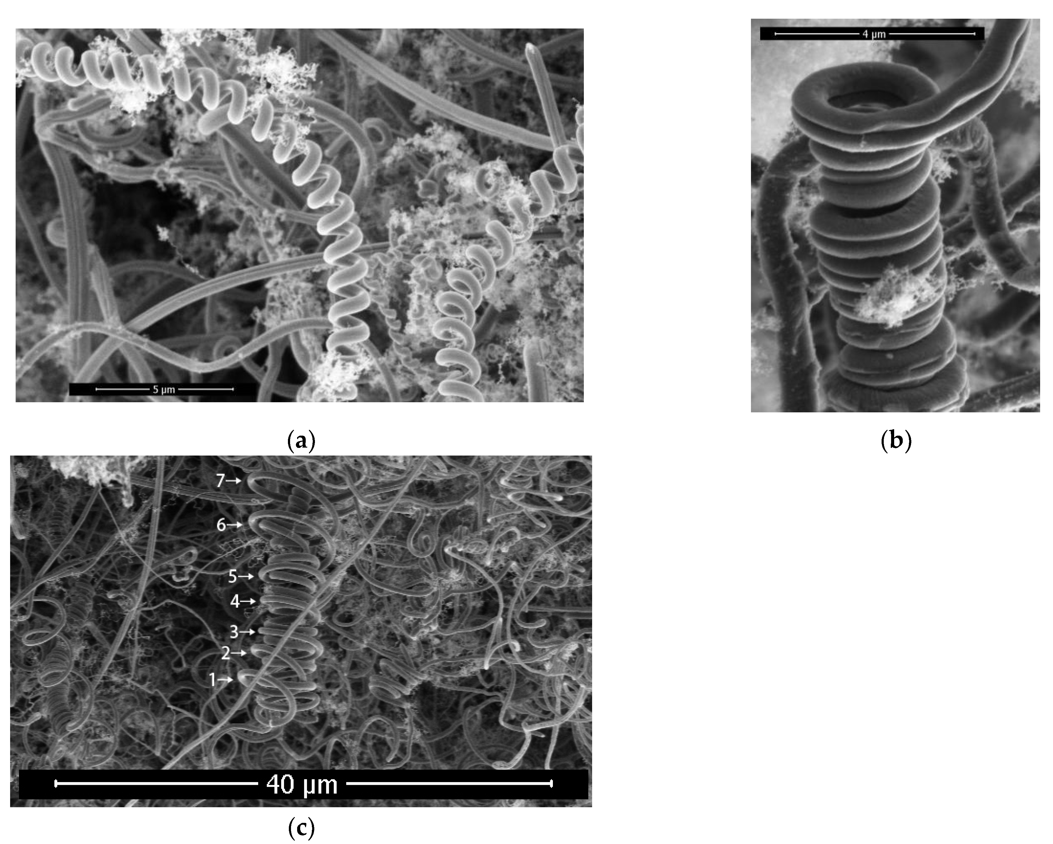
Figure 7, there is a ring appearance on a single-wire carbon fiber. With this ring as the dividing line, the growth direction of carbon fiber changes, and the curvature radius and fiber diameter at both sides of the ring basically do not change. This ring appearance of carbon fiber only indicates that the growth direction of carbon fiber has changed, which is called the change-direction ring.Arrow 1,2,3,4 indicates change-direction rings.
3.2.4. Constructing Double Helical Carbon Fibers
As shown in
Figure 8a, the growth current of the sample is 2.3A, where the fiber diameter of the single helical carbon fiber is about 0.6μm, the pitch is about 1.1μm, and the helical diameter is about 1.5μm.
Figure 8b and 8c show two different ways of constructing double helical carbon fibers.The double helical carbon fiber in
Figure 8b is formed by the double-wire carbon fiber.In FIG. 8c, there is a change-direction ring at the top of the helical carbon fiber of the sample. After the helical carbon fiber has experienced the change-direction ring, the first and second helical loops of subsequent growth are inserted into the interior of the original helical structure, the third, fourth and fifth helical loops are extended outside the original helical structure, and the helical radius of the sixth and subsequent loops numbers is gradually increased.It indicates that the helical structure after the change-direction ring is influenced by the helical structure prior to the change-direction ring.It is shown that the change-direction ring is not only the end point of the original helical carbon fiber, but also the beginning of the new helical carbon fiber.The new helical carbon fiber and the original helical carbon fiber form a double helical structure together.
3.3. Helical Carbon Fiber Skeleton
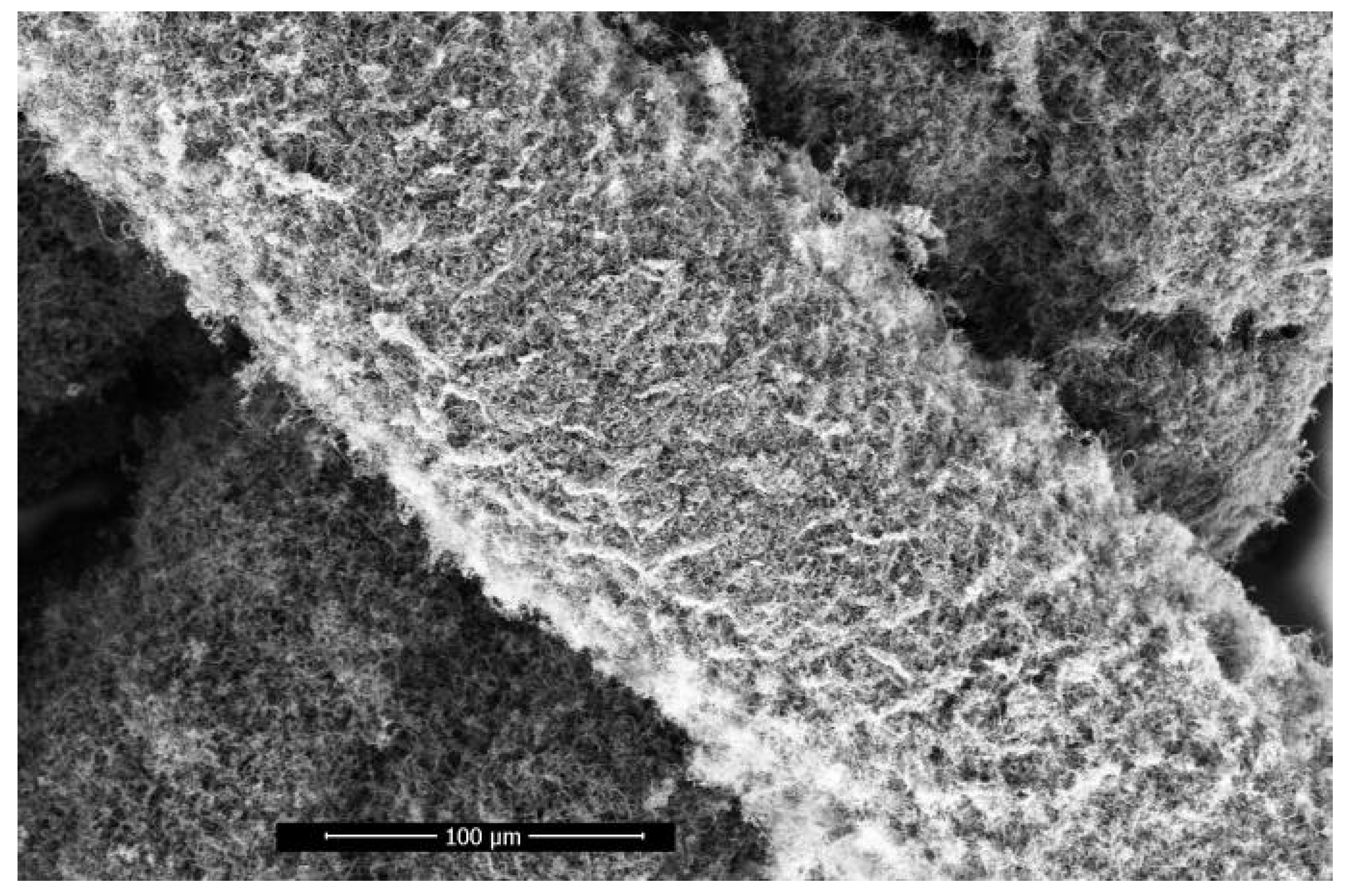
The longitudinal growth splitting mode of carbon fiber and the secondary nucleation growth mode of side wall can be carried out simultaneously, and the initial nucleation position can be spread over any side wall of carbon fiber, which has randomness. Moreover, the direction of helical growth of carbon fiber after the change-direction ring has randomness, and finally the distribution of helical carbon fiber in space has randomness.In a specific space, this random growth characteristic results in the hook of helical carbon fibers with other helical carbon fibers. As shown in
Figure 9, with increasing growth time, the helical carbon fiber eventually grows to form a carbon fiber skeleton.
3.3.1. Super-large Carbon Fiber
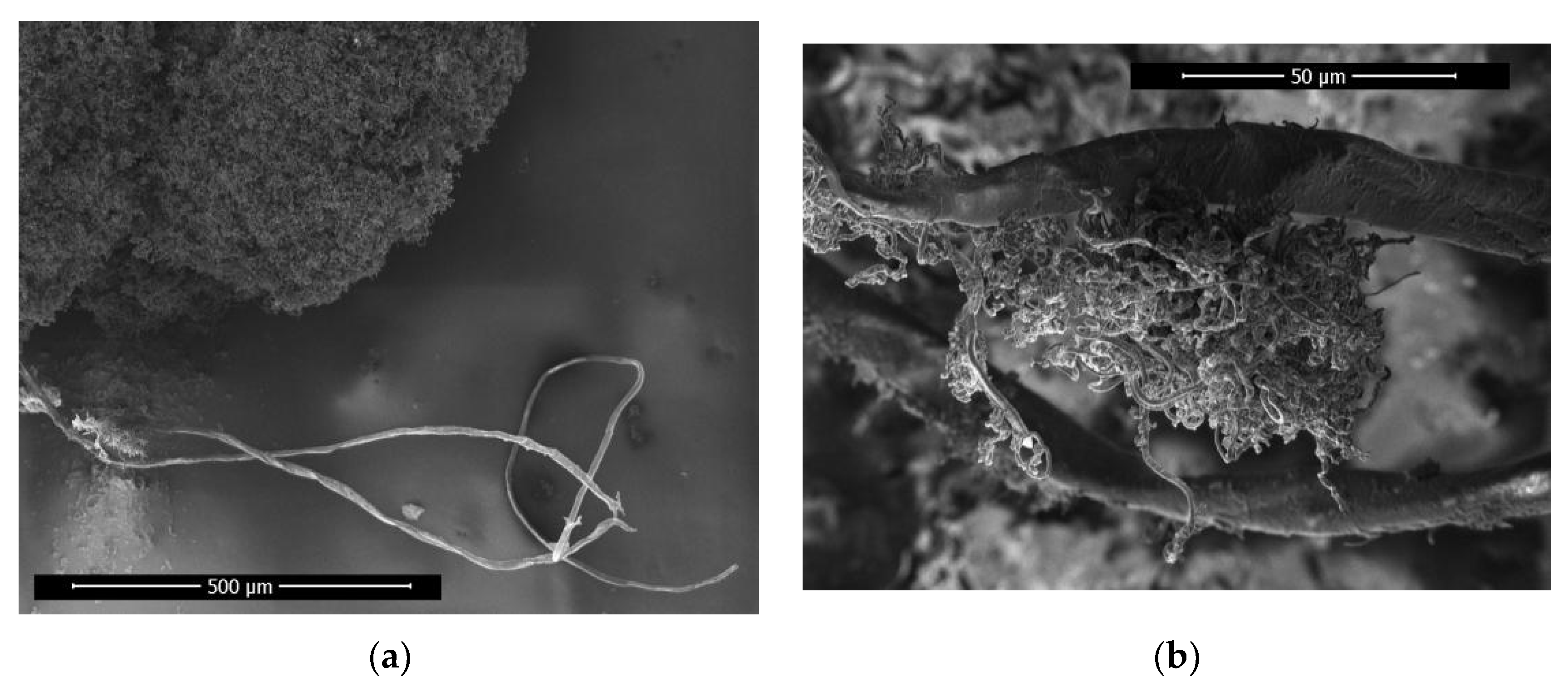
In
Figure 10a, the growth current condition of the sample is 2.4A, and a super-large carbon fiber with a diameter of about 13μm is found in the sample, which is much larger than ordinary carbon fiber.
As shown in
Figure 10b, carbon fibers with a diameter of approximately 1.3μm are grown on the super-large carbon fiber. The 1.3μm carbon fiber is considered as the product of secondary nucleation growth from the super-large carbon fiber.
Moreover, the super-large carbon fiber length is of the same order of magnitude as the length of the carbon fiber skeleton in the sample, suggesting that the super-large fiber serves as a core component for priority growth within the carbon fiber skeleton, which acts as its backbone.
3.3.2. The Torn State of The Helical Carbon Fiber Skeleton
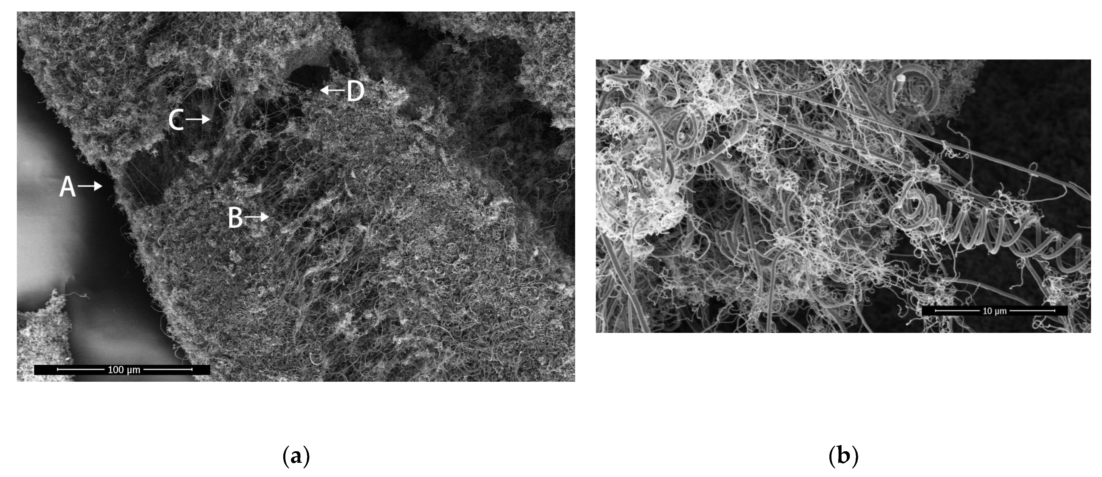
When the helical carbon fiber skeleton is subjected to external force, it will resist the external force in the form of internal carbon fiber deformation.
As shown in Figure. 11a, this is the tear diagram of the helical carbon fiber skeleton. It can be observed that there are carbon fiber links in the form of nearly straight lines at both ends of the fracture, and the carbon fibers are stretched at A,B,C,D in the figure.
The carbon fiber is stretched lengthwise along the skeleton at point A, laterally along the skeleton at point B, and diagonally in two different directions at points C and D. A,B is stretched in two perpendicular directions, therefore the carbon fiber skeleton exhibits isotropic mechanical properties.In point A,B,C,D, there are stretched helical carbon fibers on both sides of the fracture trace and broken helical carbon fibers with corresponding structures on both sides, indicating that the helical carbon fibers will deform when subjected to tension, and it will recover partial shape variables after fracture .
In
Figure 11b, a nearly straight carbon fiber passes through the middle of a broken double helical carbon fiber to form a hooked structure. The crossing point is taken as the dividing line to observe the broken double helical carbon fiber. The pitch of the left end of the dividing line is about 2.5μm and the pitch of the right end is 4μm, indicating that the right end of the structure is still visible deformation and there is still tension inside. The synergistic effect between carbon fiber and carbon fiber inside the spiral carbon fiber skeleton was demonstrated.
4. Discussion
The experimental parameters of capacitance, resistance, inductance, and voltage were held constant in the arc glow discharge device. Under specific conditions, an increase in distance resulted in a decrease in current and an increase in discharge power within the discharge zone. However, adjusting the growth current to approximately 2.2A caused excessive discharge power between the tungsten needle electrodes leading to melting and deformation of their heads. This created a vicious cycle where increasing distance further exacerbated instability during growth experiments.
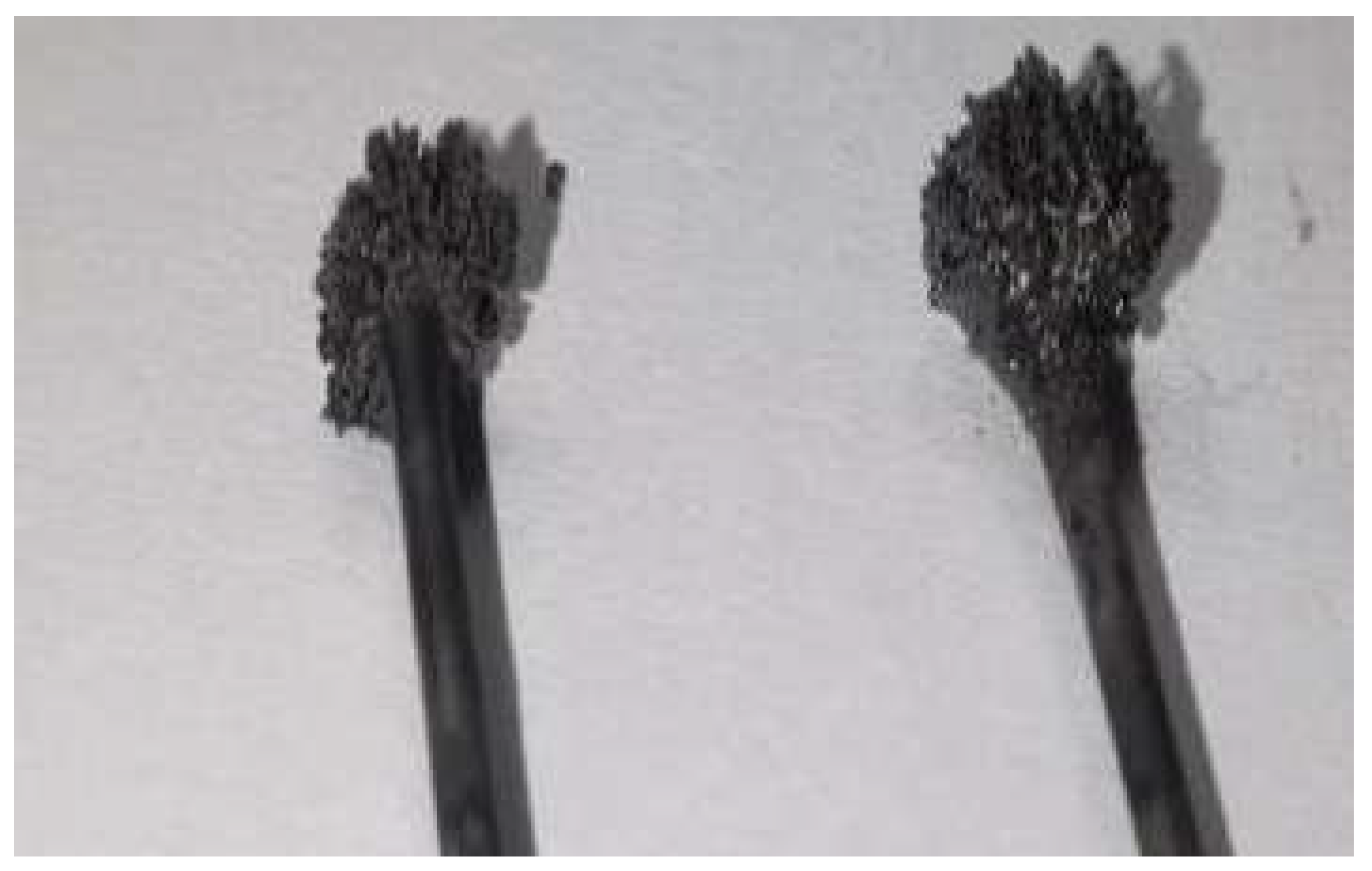
Conversely, setting the growth current at around 3.0A led to lower discharge power that allowed for appropriate head growth on tungsten needle electrodes while also causing them to become larger over time as shown by
Figure 12. Unfortunately, this eventually resulted in termination of experiments due to discharges occurring with graphite cavity side walls.Therefore, in order for the instrument to perform sample growth efficiently and continuously, the current size should be controlled between 2.3A and 2.9A.
5. Conclusions
The helical carbon fiber skeleton samples were prepared on iron wire substrate by arc glow discharge method. The diameter of the helical carbon fiber is between 0.3 and 1.1μm. The results of energy dispersive spectrum show that the carbon fiber skeleton contains neither Fe nor W element.A change-direction ring appearance indicates that the growth direction of carbon fiber has changed. It often leads to the return of the original spiral growth path, forming a double helix structure. The longitudinal growth splitting mode of carbon fiber and the secondary nucleation growth mode of side wall ware observed, which can greatly increase the specific surface area of helical carbon fiber.
Multiple nucleation and diverse growth make the helical carbon fibers hooked each other to form a helical carbon fiber skeleton.A super-large carbon fiber with a diameter of about 13μm was observed, which may be the backbone of a long helical carbon fiber skeleton. The helical carbon fiber will deform when subjected to tension, and it will recover partial shape variable after fracture . There is a synergy between carbon fiber and carbon fiber inside the helical carbon fiber skeleton. The deformation of carbon fibers due to resistance exists on the cracks in different directions, which indicates that the carbon fiber skeleton has isotropic mechanical properties. The results of this paper are helpful to promote the development of carbon fiber reinforced composites.
6. Patents
System for preparing helical carbon fiber skeleton
Xiye Chen, Haiyong Chen & Zhigang Jiang, Priority No. CN202310862380.9
References
- Chang,NK;Chang,SH.Determining Mechanical Properties of Carbon Microcoils Using Lateral Force Microscopy.Nanotechnology, IEEE Transactions on,2008,7(2): 197-201. [CrossRef]
- Tang, DM ; Liu, C; Li, F; Ren, WC; Du, JH; Ma, XL ; Cheng, HM Structural evolution of carbon microcoils induced by a direct current.Carbon,2009,47(3): 670-674. [CrossRef]
- Motojima, S.;Noda, Y.;Hoshiya, S..Electromagnetic wave absorption property of carbon microcoils in 12-110 GHz region.Journal of Applied Physics,2003,94(4): 2325-2330. [CrossRef]
- Y. Furuya;T. Hashishin;H. Iwanaga.Interaction of hydrogen with carbon coils at low temperature.Carbon,2004,42(2): 331-335. [CrossRef]
- Rakhi, R. B.;Chen, Wei;Alshareef, H. N..Conducting polymer/carbon nanocoil composite electrodes for efficient supercapacitors.Journal of Materials Chemistry,2012,22(11): 5177-5183. [CrossRef]
- K. Yoshimura;K. Nakano;T. Miyake;Y. Hishikawa;S. Motojima;.Effectiveness of carbon microcoils as a reinforcing material for a polymer matrix.Carbon,2006,44(13): 2833-2838. [CrossRef]
- Davis W R, Slawson R J, Rigby G R.An Unusual Form of Carbon . Nature,1953,171(4356):756-756. [CrossRef]
- R.T.K. Baker;M.A. Barber;P.S. Harris;F.S. Feates;R.J. Waite.Nucleation and growth of carbon deposits from the nickel catalyzed decomposition of acetylene.Journal of Catalysis,1972,26(1): 51-62. [CrossRef]
- Motojima S;Kawaguchi M;Nozaki K. Preparation of coiled carbon-fibers by catalytic pyrolysis of acetylene, and its morphology and extension characteristics.carbon,1991,29(3): 379-385. [CrossRef]
- Chen XY, Chen HY,Zhang HD,Jiang ZG.Arc Discharge Device Working at Atmospheric Pressure.Materials Sciences and Applications,2022,(6): 359-365. [CrossRef]
|
Disclaimer/Publisher’s Note: The statements, opinions and data contained in all publications are solely those of the individual author(s) and contributor(s) and not of MDPI and/or the editor(s). MDPI and/or the editor(s) disclaim responsibility for any injury to people or property resulting from any ideas, methods, instructions or products referred to in the content. |
© 2024 by the authors. Licensee MDPI, Basel, Switzerland. This article is an open access article distributed under the terms and conditions of the Creative Commons Attribution (CC BY) license (http://creativecommons.org/licenses/by/4.0/).
