1. Introduction
As the name suggests, CPP is the task of determining a path that passes over all points of an area or volume of interest while avoiding obstacles [
12,
34]. In the past decades, this kind of path planning problem has attracted significant research interest in the robotics community, due to its coverage of various practical applications, including lawn mowing [
5,
67], NC pocket machine [
6,
8,
9,
10,
1112], vacuum cleaning robot [
13141516], demining robot [
17,
18], and automated agricultural harvester [
19,
20]. Apart from the differences in their working purposes, from the perspective of the robot’s mechanical moving restriction, these works can be further classified into two groups [
5]: lawn mowing [
5,
67,
17,
18,
19,
20] and milling problems [
6,
8,
9,
10,
1112,
131415,
16]. It is worth to mention that since the robot cannot move out the cleaning area such as indoor environment, the vacuum cleaning robot should be classified as milling problem. In addition, some other specific applications [
21,
22] also should be considered as milling case. In the case of lawn mowing, the cutter head is permitted to mow over non-grass regions, while it cannot exit the pocket area in the milling process. Therefore, full coverage, which is one of the most important issue in CPP, can be easily achieved in the case of lawn mowing. On the contrary, it is difficult, if not impossible, to guarantee this kind of full coverage in the milling problem, especially in the case where the pocket has irregular corner area.
In this paper, we consider the marine survey case where torpedo-type AUVs are utilized to search given area using acoustic sonar devices [
23,
24,
2526]. For this kind of marine survey, usually there are two restricting conditions should be carefully considered in practice. One is that the vehicle cannot exit the search area (ex., port and harbor survey), and the second is that the vehicle has nonzero turning radius. At a glance, since the vehicle cannot exit its search area, this is a milling problem. However, due to its operational characteristics, the sonar sensing area can pass over this bound line. Undoubtedly, this is a significant advantage for us to design a full coverage path for marine vehicles. That said, the full coverage issue still remains as a challenge in this case, due to the fact that the vehicle is restricted to move inside the search area with nonzero turning radius.
Due to the fact that the sonar sensing area can cross over the bound line of search area, in [
27], the authors proposed a novel scheme called CbSPSA to search for a sort of optimal full coverage path for any given convex polygon. Indeed, CbSPSA is a kind of geometric solution to search a sort of shortest path in the corner area (around each vertex) of any given convex polygon. In the case of any given polygon, due to the fact that this polygon can always be divided into one or more convex polygons [
28], the CPP problem for this polygon is easy to be solved by using CbSPSA. However, in [
27], the vehicle is modeled as a particle so that can completely follow the straight line waypoint path searched by CbSPSA.
As mentioned before, for most of marine survey vehicles, they have torpedo-type mechanical appearance, and only have three control inputs (surge force, pitch and yaw moments) to handle their 6DOF 3D motion. Due to this kind of mechanical characteristics, the vehicles have nonzero turning radius. This means that in practice it is impossible for these vehicles to exactly track the straight line waypoint path, and therefore it is difficult to guarantee the vehicles’ movements to be strictly restricted inside the search area. For this reason, in this paper we extend the result of [
27] to the case where the vehicle has this kind of nonzero turning radius. In addition, some of the algorithms in [
27] are corrected and also described in more details in this paper in order for the readers more easily understand the algorithm. Here it should be noted that, for the convenience of discussion, in this paper we only consider the convex polygon case. However, due to the fact that any given polygon can always be partitioned into one or several convex polygons [
28], it is straightforward to extend the result in this paper to the general polygon case as in [
27].
The remainder of this paper is organized as follows.
Section 2 presents some of preliminaries and also clarifies the main objective of this paper.
Section 3 includes the main algorithms, both of CbSPSA and smoothing algorithm. Some numerical study is carried out in
Section 4 to demonstrate the effectiveness of proposed planning algorithms. Finally, a brief conclusion is summarized in
Section 5.
Notations: Throughout the paper,
denotes a convex polygon with
the vertices of which are arranged in clockwise.
presents the full coverage path of
with
N the number of the path waypoints
1.
denotes the Euclidean norm of vector
and
presents the azimuth angle of
.
denotes a circle with
x the center point and
r the radius.
2. Problem Statement
Recently, quite a number of unmanned vehicles have been widely utilized in the various marine surveys. And most of these vehicles, from control engineering perspective, are underactuated systems ([
29] and references therein). Due to this kind of mechanical characteristics, these vehicle have to have nonzero steady turning radius [
30]. For the convenience of discussion, the parameter
is used to denote the minimum steady turning radius.
Most of the marine surveys are aiming to search the specific sea floor area using various sonar devices [
23,
24,
2526], and the survey mission is carried out by scanning the area using sonar beam width (or swatch). Here the sonar swath is determined by the device specifications, and varies with the vehicle’s altitude from the sea floor. For the convenience of discussion, this paper only considers the simple case where the sonar swath
is kept as a constant value. This kind of constant sonar swath can be achieved in practice by forcing the underwater vehicles to keep constant altitude during the survey.
In practice, the search area for most of marine surveys is determined by a series of waypoints marked on the map. By simply connecting these points using straight lines, it is easy to get one or multiple polygons. For any given polygon, it can always be partitioned into one or several convex polygons [
28], and the coverage path for this polygon can be easily get by simply integrating all the paths in each of convex polygons [
27]. Under this consideration, in this paper we only tackle the simple convex polygon case so that can better convey the main idea of the proposed scheme.
Another interesting issue for this marine survey using acoustic sonar is that, to improve the acquired sonar image quality, the vehicle is usually required to take as less turn numbers (or inter-track numbers) as possible during the survey. Here a inter-track means a long corridor with the width of . With this in mind, the optimal concept in this paper is dedicated to that, for any given search area, the searched coverage path has the minimum turn numbers with the corresponding shortest total path length.
Consequently, for any given , the objective of thl coverage path through solving the following three sub-problemthrough solving the following three sub-problems:
-
SP1.
Full coverage path with the minimum turn numbers.
-
SP2.
The whole path is strictly located inside the search area with none of overlapped or crossed path lines. Moreover, the total length of the path should be as short as possible.
-
SP3.
The vehicle is allowed to have nonzero turning radius.
The considered in this paper is required to satisfy the following condition.
Assumption 1. For any given , each of its interior angles is larger than and also each length of its edges is larger than .
In most of the practical operations, we have . That said, appropriate attention still needs to be paid while determining the search area through selecting a series of waypoints on the map.
3. Proposed Method
3.1. Overview
The strategy for full CPP in this paper can be summarized as follows,
To solve SP1 for any given , the idea in this paper is simple that we pile the inter-tracks alongside a specific edge of so that we can cover with the minimum number of these inter-tracks.
Apply CbSPSA to solve the SP2.
Also, apply a method similar to CbSPSA combined with the circle whose radius is to round the path at each waypoint (solving SP3).
3.2. Partition: SolvingSP1and Some ofSP2
For any given
, according to its definition, it is always monotone with respect to each of its edge [
31]. For each edge
, where
is the same function of
except that
,
denotes the maximum height among the vertices
to the edge
[
27]. Here we define
, from which it is easy to verify that
is the minimum number of inter-tracks need to full cover the area
. Consequently, the strategy in this paper for the vehicle’s minimum turn number is straightforward that the vehicle is forced to search the area alongside the inter-tracks parallel to the edge corresponding to
so as to minimize the vehicle’s turn numbers.
For the convenience of discussion, in this paper all convex polygons take the same form of
, where
is the edge corresponding to
. Indeed, this kind of expression is of help to simplify the search algorithms proposed in this paper. In this case, we apply
to denote the specific vertices information for given
[
27], where
is the vertex of
to the edge
. Moreover, for vertex
, if
, then the vertex is said to be on the
LEFT; otherwise, if
, then it is on the
RIGHT.
In this paper, the vehicle’s start and end points are all set at the polygon vertices. More specifically, the start point is set as
and the end point is
with
,
, where the exact position of
is defined as following
where
.
For any given
and
, in order to avoid the possible overlapped or crossed path occurrence, the polygon
is further partitioned into three parts:
,
, and
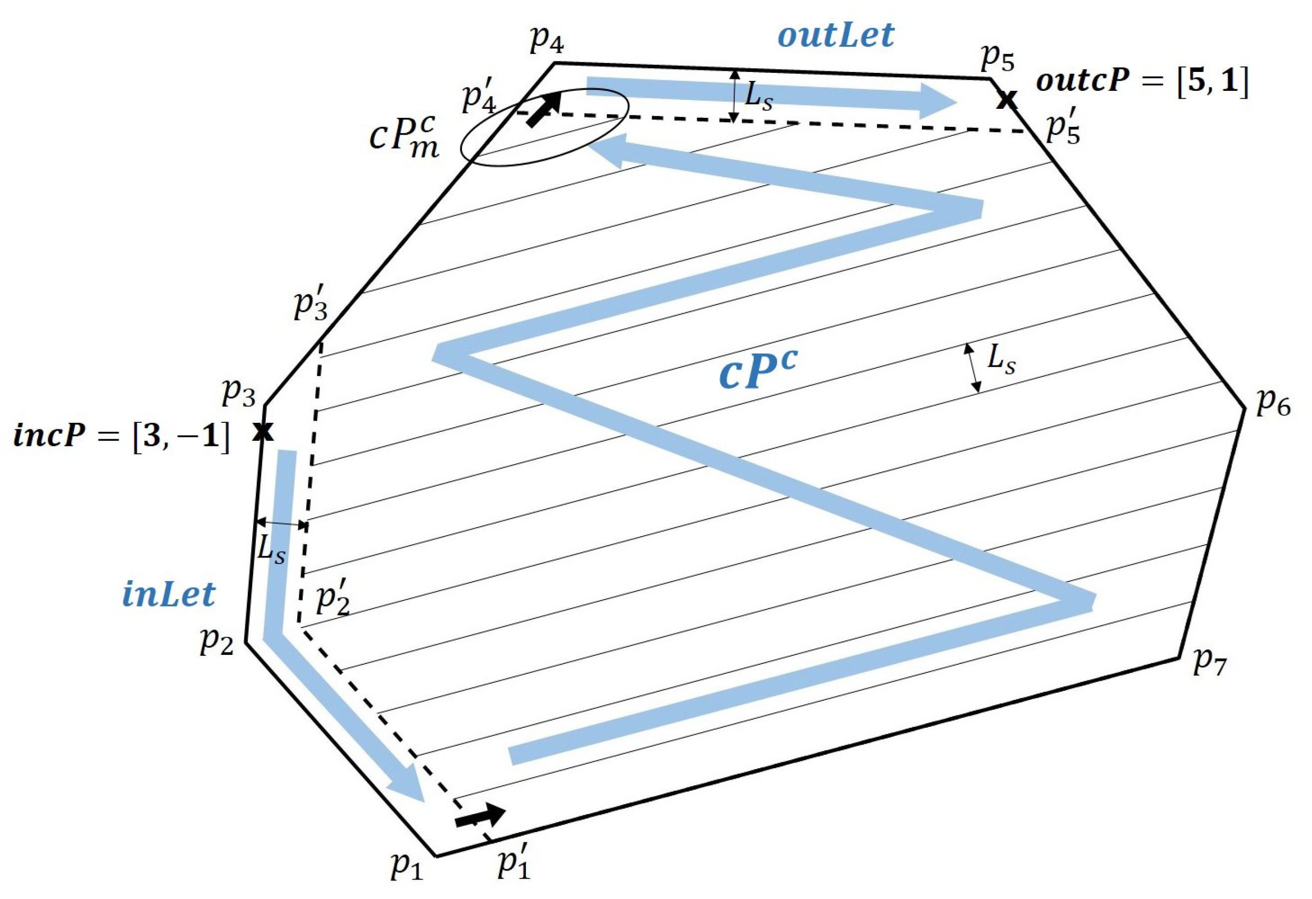
, as seen in
Figure 1. The rule of partition is that: 1) both the end of
and the start of
are connected to the one of vertices
; 2) if the end of
is linked to
, then the start part of
is to
or
, and vice versa. For details of this partition will be discussed later.
According to the partition rule, the overall full coverage for
can be constructed by
To guarantee the coverage path calculated through (
2) to have the minimum turn numbers, we need the following condition to be satisfied.
Assumption 2. Considering
in
Figure 1, its
is the same as
for
.
According to the partition rule, it is not difficult to verify that even in the case where the
Assumption 2 is not satisfied, the maximum increasing turn number calculated through (
2) will be less than 2 compare to the true minimum turn number. Therefore, in the case
, which is a very common case in practice, whether
Assumption 2 is true or not becomes less critical.
3.3. CbSPSA for : SolvingSP2
For any given
, according to the different locations of
and
, there are different partition methods. At first, the different locations of
and
can be divided into two main categories: 1) both of them are on the same side (
LEFT or
RIGHT), 2) each on the other side. It is notable that in this paper we only consider the case where
and
are not on the same vertex. In the case 1), the partition method is straightforward that: if
is closer to
, then
and
(on the
LEFT) or
(on the
RIGHT), and vice versa. In the latter case, also there are two different methods, one is
and
links to
and the other one is vice versa. However, in this case, it’s difficult to determine which one is best. In [
27], the authors choose the one whose sum of edge lengths is shorter. In this paper, this method is upgraded to that we choose the one whose total length of consequent
is shorter.
Consequently, according to (
2), simply connecting the
,
, and
at each of end and start points, we can search out the full CPP for
.
Algorithm 1 shows the overall flowchart of CbSPSA for any given convex polygon
. For given
,
return
, details of which are described in the previous subsection 3.2. The function
carries out the partition of
as seen in (
2) according to given
and
. Usually, the result of
is not unique, instead it’s possible there are several different ways of partitions, among which we will choice the one with the shortest overall waypoint path length. For the remained functions
,
, and
, they will be described in details in the following subsections.
| |
Algorithm 1:
|
| |
Input: , Output:
|
| 1 |
|
| 2 |
|
| 3 |
for
|
| 4 |
|
| 5 |
|
| 6 |
|
| 7 |
|
| 8 |
end for
|
| 9 |
return The shortest path among
|
3.3.1. CbSPSA for and
The search algorithms for
and
are the same except at the end point. At start and end points, the paths are searched using the function
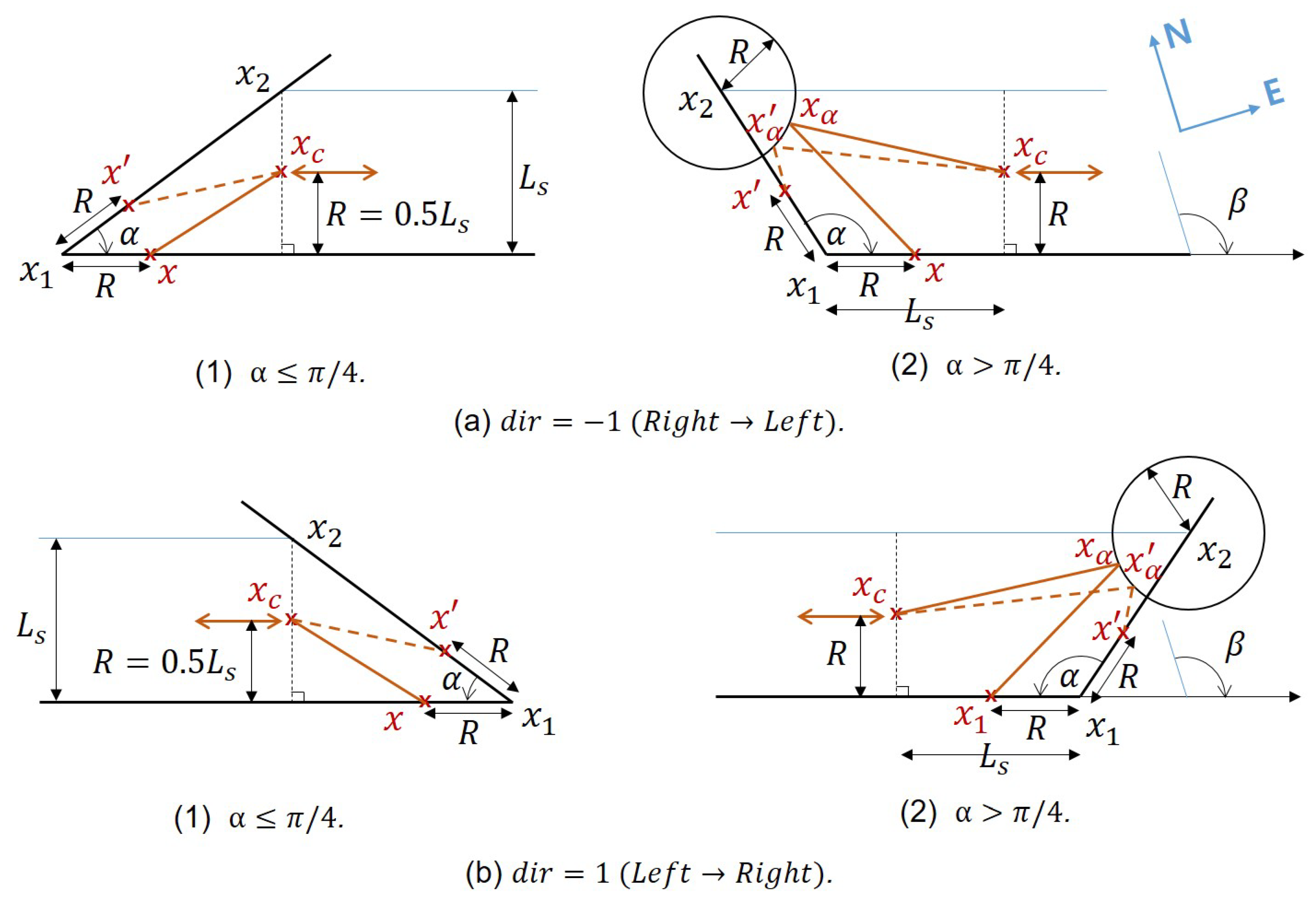
as illustrated as in
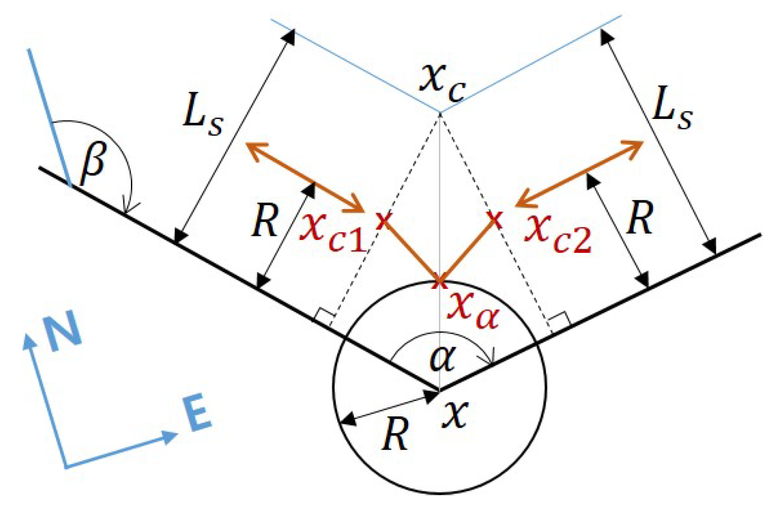
Figure 2, and at the intermediate vertices, using
which is depicted in
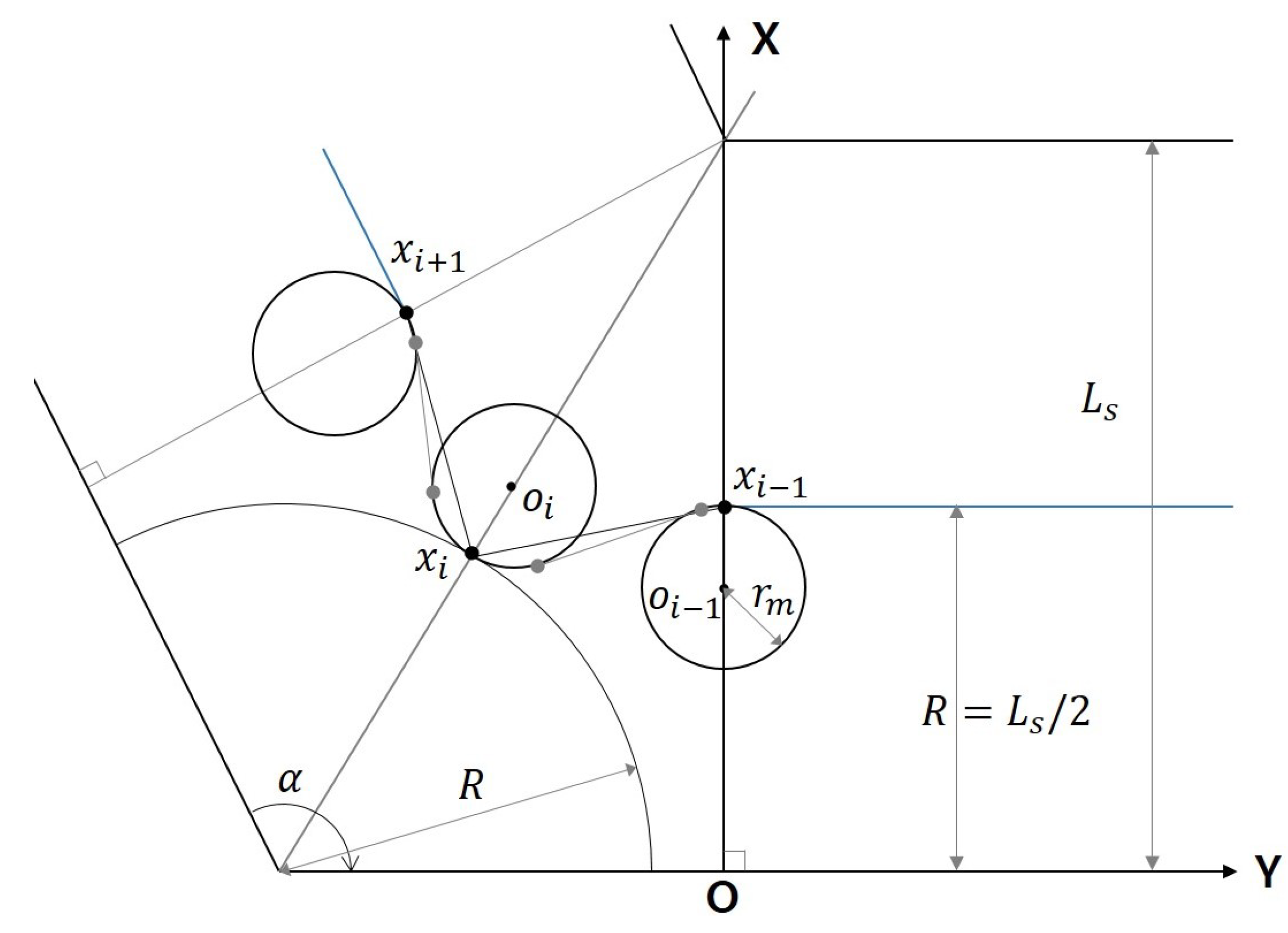
Figure 3. It is notable that in the case of
, at the end point, the waypoints are still searched using
.
3.3.2. CbSPSA for
As depicted in
Figure 1,
consists of a number of trapezoids, in other words, inter-tracks. If the vehicle is allowed to move out of the search area as in the case of lawn mowing problem [
5,
67,
17,
18,
19,
20], then CPP problem becomes straightforward that we simply extend the each centerline to the outside of the search area and just link them one by one. Unfortunately, the vehicle is restricted to move inside the search area and also has nonzero turning radius. In this case, the key issues for CPP are as follows: 1) how to link the centerlines one-by-one in the corner areas, and 2) how to design a shortest pass to cover the area
. Accordingly, the proposed search algorithm CbSPSA for
is presented as the pseudo-codes in
Algorithm 2 and
Algorithm 3. For the convenience of discussion, in the algorithm we set
and
or
.
In
Algorithm 2, the state variable
is defined as in
Table 4 and accordingly
is constructed as
, where
if
and
if
2. Also, the parameter
in the algorithm can be determined according to
Table 5. Here it is worth to mention that, considering
Figure 1 where
is connected to
of
which is taken as
in the algorithm, the direction of
should be reversed.
| |
Algorithm 2:
|
| |
Input: , Output:
|
| 1 |
|
| 2 |
|
| 3 |
:=, := |
| 4 |
for
|
| 5 |
if
|
| 6 |
Set with , , and
|
| 7 |
|
| 8 |
else
|
| 9 |
X:=last way point of
|
| 10 |
|
| 11 |
if
|
| 12 |
|
| 13 |
end if
|
| 14 |
end if
|
| 15 |
end for
|
| 16 |
return
|
As mentioned before, one of main upgrade in this paper is that each waypoint of
consists of
instead of
as in [
27], where
is the horizontal position and the integer parameter
indicates an additional information about
. If
is located on the center line of inter-track, then we set
, otherwise
. This kind of information will be used in the later smoothing process for
. On the other hand, in the algorithm, the function
is similar to
[
27] and
is to
in [
27], respectively. The difference is that the differentiation criteria is changed from
as in
Figure 6 in [
27] to
. This is for the convenience of path smoothing for the vehicle’s nonzero turning radius, details of which will be discussed later.
The
Algorithm 2 in [
27] is also upgraded as follows. Here the detailed description of
and
are presented in
Appendix A and
B. This kind of detailed presentation is supposed to be of help for the readers’ in depth understanding of the proposed algorithm. The remainder of
is similar to
and
is to
. The only difference is the search direction.
| |
Algorithm 3:
|
| |
Input: , Output:
|
| 1 |
|
| 2 |
case 1. ,
|
| 3 |
|
| 4 |
case 2. ,
|
| 5 |
|
| 6 |
case 3. ,
|
| 7 |
|
| 8 |
case 4. ,
|
| 9 |
|
| 10 |
end case
|
| 11 |
return
|
3.4. Smoothing : Solving SP3
Here we recall some features of
searched by CbSPSA. For given
, since there are total of
number of trapezoids, there are same number of center line pieces in
[
27], each of which corresponds to two adjacent waypoints. Therefore, there are total of
number of waypoints in
on the center lines, and the remainder ones are not on these lines. This kind of information is encoded to the integer parameter in
.
indicates
is on the center line, and
means it is not. Furthermore, each pair of adjacent waypoints are connected by straight lines [
27]. In order for the vehicles, which have nonzero turning radius, to exactly follow it, this
has to go through a specific smoothing process.
The smoothing process proposed in this paper is as the following
Algorithm 4, and also depicted in
Figure 4,
Figure 5 and
Figure 6. In the algorithm, the function
is used to check if the point
x is located inside the polygon
. If it is, then returns TRUE; otherwise, return FALSE. The integer parameter
in
is encoded in different way.
indicates the path from
is turning clockwise alongside the circle with
the radius until the next waypoint,
means anticlockwise, and
is the straightforward motion.
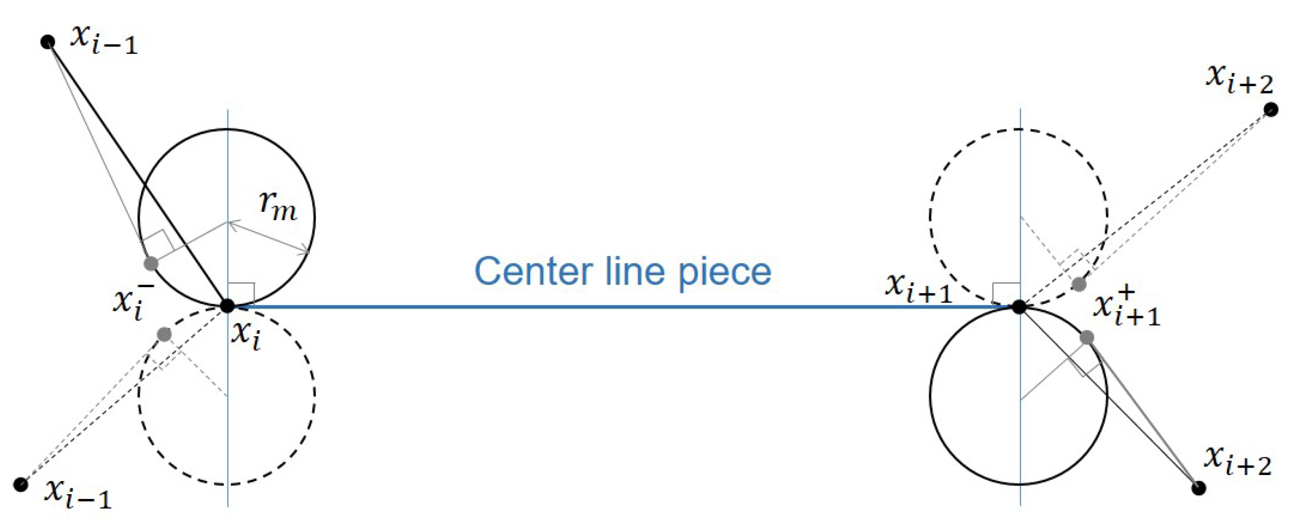
There are a few points need to be mentioned here. First, according to the
Assumption 1, it is not difficult to verify that two points
and
, as in the case of
Figure 5, cannot be located outside of
at the same time. And more interestingly, it is always possible for us to find out a proper value of
so that both of
and
are all located inside
. Second, consider the case where one of
and
is located inside the circle
3, see
Figure 5. In this case, we can easily turn around the circle until the inside point is relocated outside the circle. For example, if
is located inside the circle, then clockwise turning around the circle can easily relocate the point outside of it. Finally, let us consider an exceptional case as seen in
Figure 3, which is the combination of
Figure 4 and
Figure 5. In this case, the path smoothing process can be depicted as in
Figure 6, from which we can see that it seems possible that two circles
and
can cross each other. In this case, it’s impossible to search out a path using
Algorithm 4. With this in mind, in this paper we propose the following proposition.
| |
Algorithm 4:
|
| |
Input: , Output:
|
| 1 |
|
| 2 |
for i=2:(N-1) |
| 3 |
if
|
| 4 |
Calculate or as in Figure 5
|
| 5 |
or
|
| 6 |
else if
|
| 7 |
Calculate and according to Figure 6(a) |
| 8 |
while(!) |
| |
Increasing and calculate and according to Figure 6(b) |
| 9 |
while(!) |
| |
Increasing and calculate and according to Figure 6(c) |
| 10 |
|
| 11 |
end if
|
| 12 |
end for
|
| 13 |
|
| 14 |
return
|
Proposition 1. Consider
Figure 6. If
satisfies
, then we have
,
.
Proof (Proof of Proposition 1). See Appendix. □
Figure 6.
Path smoothing in the case of
Figure 3.
Figure 6.
Path smoothing in the case of
Figure 3.
Here it’s notable that
is a kind of sufficient condition, not a necessary one. With this condition, we can guarantee that all the waypoints in
can be properly smoothed so that the vehicle can exactly follow the path and further can guarantee the coverage path planning objective mentioned in Section II to be achieved.
4. Numerical Study
In this section, we carry out some of numerical simulations in MATLAB to further illustrate the proposed path planning algorithm. In the simulation, we consider the convex polygon as
with
and
as seen in
Figure 1. For the parameters, the sonar swath is taken as
, and the vehicle’s minimum turn radius is set as
so that can satisfy the condition in
Proposition 1.
First,
returns
, which means the height from the vertex
to the edge
is the shortest. So the inter-track will be piled alongside
. Then, we investigate the convex polygon partition method
. As mentioned before, since
is located on
LEFT side and
is on the
RIGHT side, there are total of two partition methods, which means
in
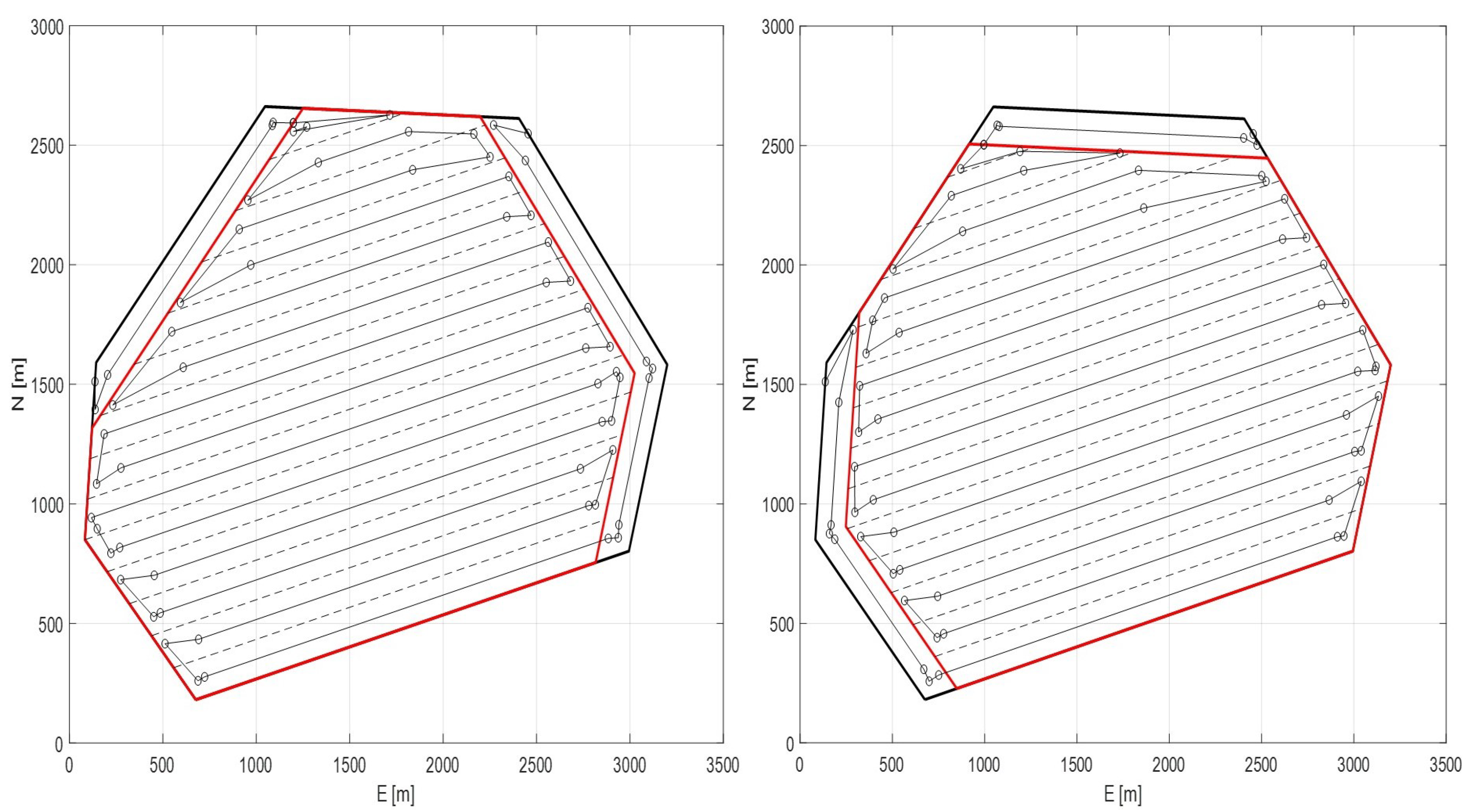
Algorithm 1. Corresponding results are shown in
Figure 7. In the left case, the total length of
is 39382m, and for right one, the length is 38326m. Therefore,
Algorithm 1 return the coverage path as shown in right side in
Figure 7.
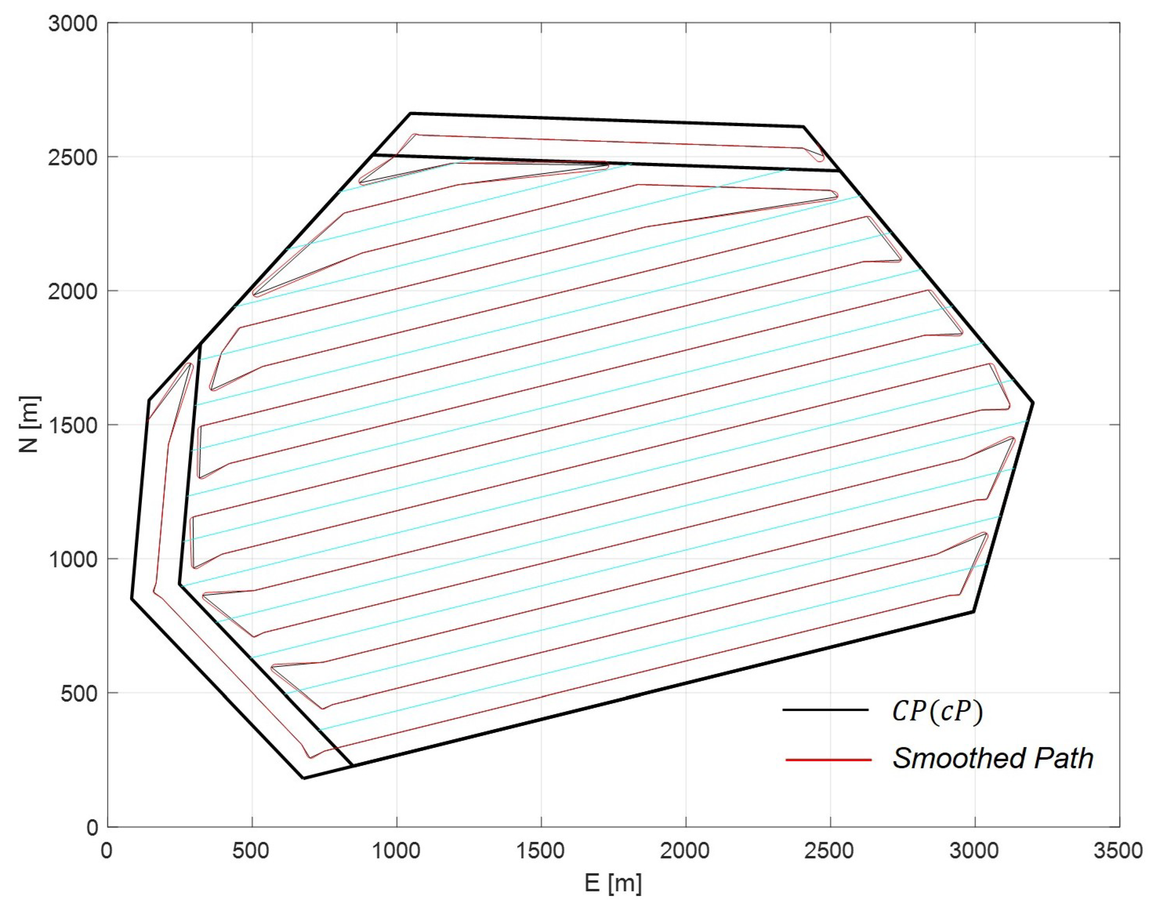
Now consider the path smoothing algorithm proposed in this paper. For the coverage path
searched by
Algorithm 1, we apply the smoothing method (
Algorithm 4 in subsection 3.4) and the corresponding result is shown in
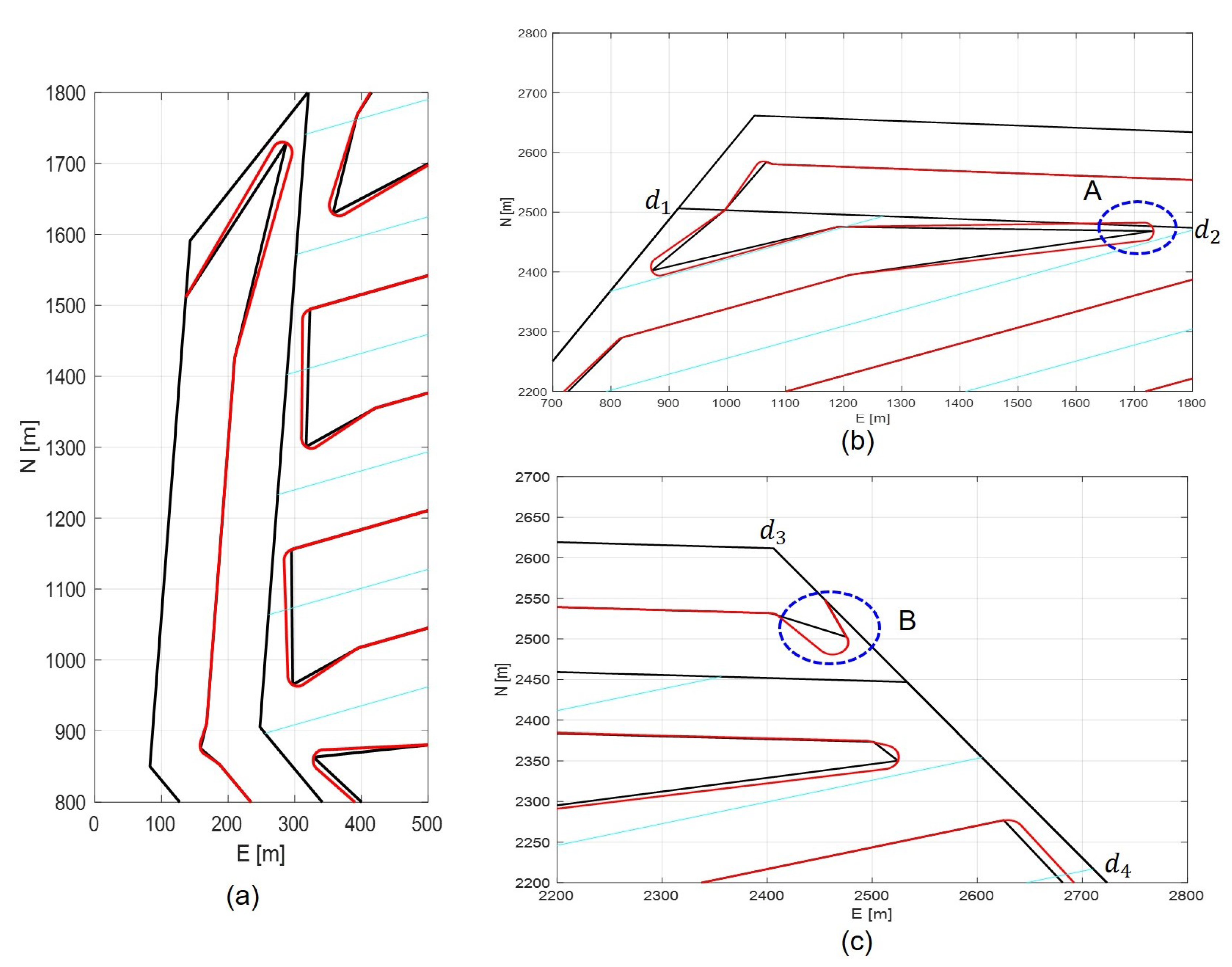
Figure 8. And
Figure 9 shows some of the enlarged corner screen of
Figure 8. From these results, we can see that the proposed smoothing method can provide a sort of satisfactory smoothing performance while can guarantee the result path all restricted inside the search area. Here it is worth to mention that in the case A as seen in
Figure 9(b), since
, which is the common tangent between
and
, is located inside the polygon
, the smoothed path has intersection with
. In contrast, in the case of B as seen in
Figure 9(c),
is the edge of
, therefore the smoothed path has this kind of form so that to locate the path inside the polygon
.
Finally,
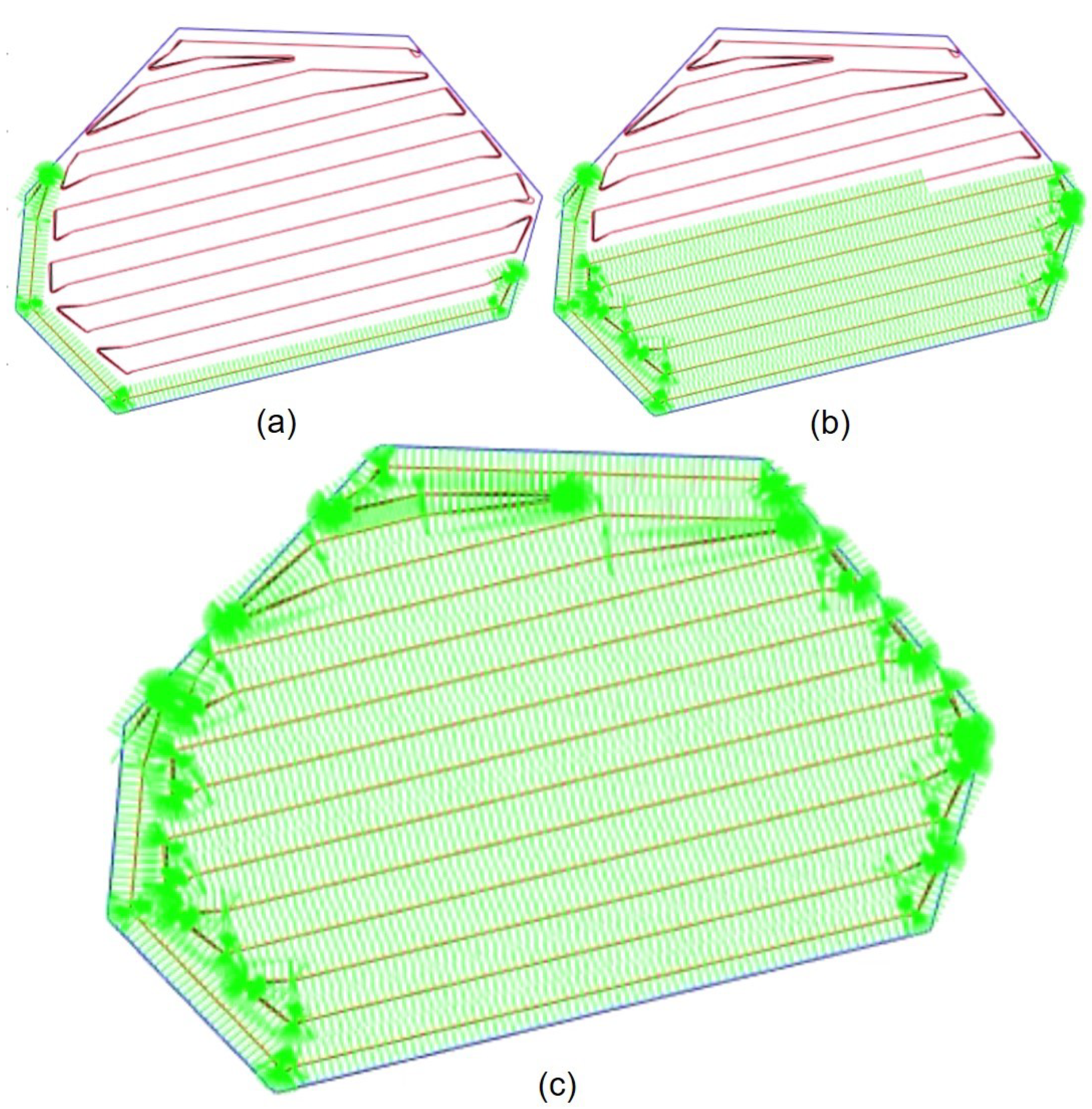
Figure 10 shows the final sonar full coverage result after the vehicle finishes the trajectory following for given smoothed coverage path. Each green line indicates the sonar swath, and from
Figure 10, we can see that the sonar swath fully covers the given polygon area
, while the vehicle keeps moving inside the polygon.
5. Conclusion
A full CPP method for marine survey where the vehicles have nonzero minimum turn radius has been presented in this paper. For any given convex polygon search area, it can be partitioned into three parts: , , and . At each area, the coverage path is searched using proposed CbSPSA algorithm, and finally integrating these three path can easily construct the final waypoint path. For this straight line waypoint path, we have further proposed a smoothing algorithm so that for the vehicles with nonzero turning radius can exactly track the searched coverage path. Numerical analysis also has been carried out to illustrate the effectiveness of proposed schemes.
The current results in both of this paper and [
27] are limited to the convex polygon and some of relatively simple polygon cases. How to extend these results to the case of more general form of polygon search areas might be one of our interesting future works.
Author Contributions
Conceptualization, J.-H.L. and H.K.; methodology, J.-H.L.; software, J.-H.L., H.K., and H.-S.J.; validation, J.-H.L., H.K., M.-G.K., M.-J.L., and H.-S.J; formal analysis, J.-H.L. and H.K.; investigation, J.-H.L.; resources, J.-H.L.; data curation, J.-H.L.; writing—original draft preparation, J.-H.L.; writing—review and editing, J.-H.L.; visualization, J.-H.L. and M.-G.K.; supervision, J.-H.L.; project administration, J.-H.L.; funding acquisition, J.-H.L. All authors have read and agreed to the published version of the manuscript.
Funding
This work was supported in part by the project titled “AUV Fleet and its Operation System Development for Quick Response of Search on Maritime Disasters" of Korea Institute of Marine Science & Technology Promotion (KIMST) funded by the Korea Coast Guard Agency (KIMST-20210547), and in part by Korea Institute of Marine Science & Technology Promotion(KIMST) funded by the Ministry of Oceans and Fisheries(RS-2023-00256122), both in Republic of Korea.
Institutional Review Board Statement
The study did not require ethical approval.
Informed Consent Statement
Not applicable.
Data Availability Statement
Data available on request.
Conflicts of Interest
The authors declare no conflicts of interest.
Abbreviations
The following abbreviations are used in this manuscript:
| CPP |
Coverage path planning |
| AUV |
Autonomous underwater vehicle |
| CbSPSA |
Calculation based shortest path search algorithm |
| DOF |
Degree of freedom |
Appendix A. Function calPoints21(x 1 ,cP m c ,stat)
1
2 if
3 if
4
5 if
6
7 end if
8 end if
9
10 if
11
12 if
13
14 end if
15 end if
16 else if
17
18 if
19
20 end if
21 end if
22 last waypoint of
23
24
25 return
Appendix B. Function calPoints22(x 1 ,cP m c ,stat)
1
2 if
3 if
4
5 if
6
7 end if
8 end if
9
10
11 if
12
13 if
14
15 if
16
17 end if
18 end if
19 else if
20
21 if
22
23 end if
24 end if
25 end if
26 return
Appendix C. Proof of Proposition 1
From
Figure 7, it is easy to get
and
, from which further we have
With
, (
A1) can be rewritten as following
from which it is easy to get
Since
, we have
, from which it isn’t difficult to verify that, if
, then we have
. This means that
is a strictly monotone increasing function. On the other hand, if we set
in (
A3), then we have
, from which it is easy to verify that if
, then
. As a result, we can get
, which means that
is monotone decreasing function with
. Consequently, we can get that if
, then
. This concludes the proof. □
References
- Choset, H. Coverage for robotics – A survey of recent results. Annals of Mathematics and Artificial Intelligence 2001, 31, 113–126. [Google Scholar] [CrossRef]
- Galceran, E.; Carreras, M. A survey on coverage path planning for robotics. Robotics and Autonomous Systems 2013, 61, 1258–1276. [Google Scholar] [CrossRef]
- Bormann, R.; Jordan, F.; Hampp, J.; Hagele, M. Indoor Coverage Path Planning: Survey, Implementation, Analysis. In Proceedings of IEEE International Conference on Robotics and Automation, Brisbane, Australia, 2018, 1717–1725.
- Taua, M. C.; Lisane, B. B.; Ferreira, R. R. Survey on Coverage Path Planning with Unmanned Aerial Vehicles. Drones 2019, 3. [Google Scholar] [CrossRef]
- Arkin, E. M.; Fekete, S. P.; Mitchell, S. B. Approximation algorithms for lawn mowing and milling. Computational Geometry 2000, 17, 25–50. [Google Scholar] [CrossRef]
- Huang, Y. Y.; Cao, Z. L.; Oh, S. J.; Kattan, E. U.; Hall, E. L. Automatic Operation for a Robot Lawn Mower. In Proceedings of SPIE 0727, Feb., 2000. [Google Scholar]
- Hofmann, M.; Clemens, J.; Stronzek-Pfeifer, D.; Simonelli, R.; Serov, A.; Schettino, S.; Runge, M.; Schill, K.; Buskens, C. Coverage Path Planning and Precise Localization for Autonomous Lawn Mowers. In Proceedings of 6th IEEE International Conference on Robotic Computing, 3–5 Dec., 2022, 238–242.
- Vosniakos, G. and Papapanagiotou, P. Multiple tool path planning for NC machining of convex pockets without islands. Robotics and Computer Integrated Manufacturing 2000, 16, 425–435. [Google Scholar] [CrossRef]
- Chen, X.; Tucker, T. T.; Kurfess, T. R.; Vuduc, R.; Hu, L. Max orientation coverage: efficient path planning to avoid collisions in the CNC milling of 3D objects. Proceedings of IEEE/RSJ International Conference on Intelligent Robots and Systems, Oct. 2020, Las Vegas, NV; 6862–6869. [Google Scholar]
- Held, M. On the Computational Geometry of Pocket Maching, Lecture Notes in Computer Science, 500, Springer, New York, 1991.
- Dhanik, S. and Xirouchakis, R. Contour parallel milling tool path generation for arbitrary pocket shape using a fast marching method. International Journal of Advanced Manufacturing Technology 2010, 50, 1101–1111. [Google Scholar] [CrossRef]
- Venkatesh, R.; Vijayan, V.; Parthiban, A.; Sathish, T.; Chandran, S. S. Comparison of different tool path pocket milling. International Journal of Mechanical Engineering and Technology 2018, 9, 922–927. [Google Scholar]
- Yasutomi, F.; Yamada, M.; Tsukamoto, K. Cleaning robot control. In Proceedings of IEEE International Conference on Robotics and Automation, 1988, Philadelphia, PA, 1839–1841.
- Hofner, C. and Schmidt, G. Path planning and guidance techniques for an autonomous mobile cleaning robot. Robotics and Autonomous 1995, 14, 199–212. [Google Scholar] [CrossRef]
- Prassler, E.; Ritter, A.; Schaeffer, C.; Fiorini, P. A Short History of Cleaning Robots. Autonomous Robots 2000, 9, 211–226. [Google Scholar] [CrossRef]
- Miao, X.; Lee, J.; Kang, B. Y. Scalable Coverage Path Planning for Cleaning Robots Using Rectangular Map Decomposition on Large Environments. IEEE Access 2018, 6, 38200–38215. [Google Scholar] [CrossRef]
- Acar, E. U.; Choset, H.; Zhang, Y.; Schervish, M. Path Planning for Robotic Demining: Robust Sensor-based Coverage of Unstructured Environments and Probabilistic Methods. The International Journal of Robotics Research 2003, 22, 441–466. [Google Scholar] [CrossRef]
- Seder, M. and Petrovic, I. Complete coverage path planning of mobile robots for humanitarian demining. Industrial Robot 2012, 39, 484–493. [Google Scholar]
- Stoll, A. and Kutzbach, D. Guidance of a Forage Harvester with GPS. Precision Agriculter 2000, 2, 281–291. [Google Scholar] [CrossRef]
- Oksanen, T. and Visala, A. Coverage Path Planning Algorithms for Agricultural Field Machines. Journal of Field Robotics 2009, 26, 651–668. [Google Scholar] [CrossRef]
- Wong, S. C. and MacDonald, B. A. A topological coverage algorithm for mobile robots. In Proceedings of IEEE/RSJ International Conference on Intelligent Robots and Systems, Oct. 2003, Las Vegas, NV; 1685–1690. [Google Scholar]
- Tang, J.; Sun, C.; Zhang, X. MSTC*:Multi-robot Coverage Path Planning under Physical Constraints. Proceedings of 2021 IEEE International Conference on Robotics and Automation, Xi’an, China, 2518–2524. 2021. [Google Scholar]
- Paull, L.; Saeedi, S.; Seto, M.; Li, H. Sensor-Driven Online Coverage Planning for Autonomous Underwater Vehicles. IEEE/ASME Transactions on Mechatronics 2013, 18, 1827–1838. [Google Scholar] [CrossRef]
- Sun, B.; Zhu, D.; Tian, C.; Luo, C. Complete Coverage Autonomous Underwater Vehicles Path Planning Based on Glasius Bio-Inspired Neural Network Algorithm for Discrete and Centralized Programming. IEEE Transactions on Cognitive and Developmental Systems 2019, 11, 73–84. [Google Scholar] [CrossRef]
- Yordanova, V.; Gips, B. Coverage Path Planning With Trackn Spacing Adaptation for Autonomous Underwater Vehicles. IEEE Robotics and Automation Letters 2020, 5, 4774–4780. [Google Scholar] [CrossRef]
- Bagnitckii, A.; Inzartsev, A.; Pavin, A. Planning and correction of the AUV coverage path in real time. Proceedings of 2017 IEEE Underwater Technology, Busan, Korea, Feb. 2017. [Google Scholar] [CrossRef]
- Li, J. H.; Kang, H.; Kim, M. G.; Jin, H.; Lee, M. J.; Cho, G. R.; Bae, C. Full Coverage of Confined Irregular Polygon Area for Marine Survey. IEEE Access 2023, 11, 92200–92208. [Google Scholar] [CrossRef]
- Stefan, H.; Kurt, M. Fast triangulation of simple polygons. Foundations of Computation Theory 1983, Lecture Notes in Computer Science. Berlin, Heidelberg, Springer, 158: 207–218.
- Li, J. H. 3D trajectory tracking of underactuated non-minimum phase underwater vehicles. Automatica 2023, 155, 111149. [Google Scholar] [CrossRef]
- Fossen, T. I. Guidance and Control of Ocean Vehicles. John Wiley & Sons Ltd., chichester, UK.
- Heckbert, P. S. Testing the Convexity of a Polygon. Academic Press, London, UK.
| 1 |
This kind of redefinition of full coverage path is another main upgrade to the authors’ previous work [ 25]. |
| 2 |
In this paper we only consider the case where there is maximum of one vertex between and . Also, maximum of one vertex between and . From the practical point of view, this is also quite a reasonable consideration. |
| 3 |
Fortunately, so far the authors have not encounter the case where these two points are inside the circle at the same time. Indeed, with this in mind, the point in Figure 2(a2) and Figure 2(b2) is set away from . |
|
Disclaimer/Publisher’s Note: The statements, opinions and data contained in all publications are solely those of the individual author(s) and contributor(s) and not of MDPI and/or the editor(s). MDPI and/or the editor(s) disclaim responsibility for any injury to people or property resulting from any ideas, methods, instructions or products referred to in the content. |
© 2024 by the authors. Licensee MDPI, Basel, Switzerland. This article is an open access article distributed under the terms and conditions of the Creative Commons Attribution (CC BY) license (http://creativecommons.org/licenses/by/4.0/).
