
Submitted:
27 July 2024
Posted:
30 July 2024
You are already at the latest version
Abstract
This study investigates the fatigue behavior of cold-finished mild steel subjected to electrochemical hydrogen charging under controlled conditions. Samples were hydrogenated at constant time in a fixed electrolyte pH after which they underwent fatigue testing under constant loading condition with fixed frequency. The primary objective was to assess the impact of varying hydrogen permeation levels on the number of cycles to failure. The experimental results revealed a complex relationship between hydrogen concentration and fatigue life. Initially, as hydrogen permeation increased, the number of cycles to failure substantially decreased, demonstrating a detrimental effect of diffused hydrogen on fatigue resistance of samples. This decline in fatigue life was attributed to hydrogen embrittlement (HE) and hydrogen-enhanced decohesion (HEDE) phenomena, which collectively facilitate crack initiation and propagation. However, at high hydrogen concentrations, an unexpected increase in number of cycles to failure was observed suggesting the existence of a threshold hydrogen concentration beyond which the fatigue mechanisms may be altered, potentially due to saturation of hydrogen-related defects and mechanisms such as Hydrogen Enhance Localized Plasticity (HELP). The insights gained from this research have significant implications for the material's application in hydrogen-rich environments, such as those encountered in the energy and transportation industries.
Keywords:
cathodic charging
; cyclic loading
; hydrogen embrittlement
; diffusible hydrogen
1. Introduction
Hydrogen embrittlement (HE) arises when hydrogen atoms permeate into a metal, often during exposure to hydrogen-rich environments in processes such as operational exposure in scenarios like high-pressure hydrogen storage, acidic, or alkaline conditions. This infiltration of hydrogen can destabilize the metal through several mechanisms: it diminishes the cohesive forces between metal atoms (a phenomenon known as decohesion) [1,2], facilitating the initiation and propagation of cracks. Additionally, certain metals, notably titanium and zirconium, may react with hydrogen to form brittle metal hydrides [3], enhancing their susceptibility to cracking. Additionally, diffused hydrogen can induce localized slipping within the metal’s crystal structure, triggering premature failure under stress.
Fatigue failure occurs when a material progressively weakens and ultimately fractures under repeated cycles of stress levels below the material’s ultimate tensile strength [4,5]. This failure initiates at stress concentrators such as notches, holes, or surface imperfections, where cracks start to form and subsequently extend with each load cycle. The propagation rate of these cracks hinges on the applied stress range [6,7] such as alternating tension and compression, and the properties of the material [8,9,10] including chemical composition, microstructure (grains arrangement and size), fracture toughness, and hardness. Eventually, the crack reaches a critical size, rendering the remaining cross-sectional area inadequate to bear the load, which leads to a sudden material fracture with little to no forewarning. HE and fatigue failure, though distinct phenomena, are closely interlinked and can significantly compromise the structural integrity and lifespan of metallic components, particularly in high-stress engineering environments. The interaction between these two processes is crucial for understanding their combined impact on material failure.
The presence of hydrogen notably accelerates fatigue failure in metals [11], primarily through reduction of the energy required to initiate cracks. Hydrogen intensifies the rate of crack propagation during each fatigue cycle as it promotes localized plasticity [12] and reduces the fracture toughness of the material at the crack tip. This leads to accelerated crack growth under cyclic loading. HE also lowers the threshold stress intensity factor for crack growth [13,14], allowing cracks to extend at lower stress intensities than those observed in non-embrittled metals. Consequently, hydrogen presence significantly diminishes the fatigue life of a component, with cracks forming sooner and extending more rapidly.
In a study examining the impact of diffusible hydrogen on the fatigue life of spot welds in high-tensile-strength steel sheets [15], researchers found that both the number of cycles to failure and the endurance limit decreased as the diffusible hydrogen content increased at a constant amplitude-loading frequency. This phenomenon was attributed to the accumulation of hydrogen and its influence on crack growth behavior, facilitated by two primary mechanisms: hydrogen-enhanced local plasticity (HELP) and hydrogen-enhanced strain-induced vacancies (HESIV).
The HELP mechanism reveals how hydrogen contributes to localized increase in plastic deformation around stress concentrators [16,17], which can lead to the early onset of material failure. On the other hand, the HESIV mechanism focuses on how hydrogen affects the metal's microstructural properties [17]. Specifically, it emphasizes the interaction between hydrogen and the vacancies that arise from irregularities in dislocation movement during plastic deformation. This interaction leads to an increased concentration of vacancies, which significantly impacts the metal's mechanical properties. These vacancies may coalesce into microvoids or facilitate the nucleation of microcracks. Under cyclic loading, these microvoids and microcracks are prone to expansion, resulting in premature material failure.
Another comprehensive study conducted on the fatigue crack growth characteristics of electron beam melted Ti-6Al-4V alloy in a high-pressure hydrogen environment demonstrated a notably faster fatigue crack growth rate [18] compared to that observed in air. This escalated rate of crack propagation was attributed to several hydrogen-related mechanisms that intensify the fatigue behavior of this titanium alloy. The primary mechanism cited by the researchers is HELP [19], which suggests that the presence of hydrogen facilitates increased localized plastic deformation at the crack tip. This deformation accelerates the crack growth under cyclic loading conditions. Additionally, the study referenced the adsorption-induced dislocation emission (AIDE) mechanism [20], which involves hydrogen atoms reducing the energy barrier for dislocation emission at the crack tip. This process enhances the mobility of dislocations, contributing to the rapid expansion of the crack.
Furthermore, hydrogen-enhanced decohesion (HEDE) [2] was identified as a critical factor influencing the alloy's fatigue performance. This mechanism proposes that hydrogen atoms weaken the metallic bonds within the material's lattice structure, particularly around the crack tip, thereby promoting the separation of the lattice and facilitating crack extension. These findings were thoroughly contextualized in a review by Lynch [20], which provides a detailed analysis of these mechanisms.
Given the synergistic effects between hydrogen embrittlement and fatigue failure, it is imperative for engineers to consider both factors when designing and selecting materials for applications likely to encounter hydrogen exposure or where high-cycle fatigue is anticipated. This dual consideration is essential to enhance safety and reliability in such applications.
In the transition toward sustainable energy systems and the reduction of carbon emissions, the co-firing of hydrogen (H2) with natural gas emerges as a critical technology for cleaner power generation [21,22,23,24]. Hydrogen can significantly contribute to this transition by displacing gaseous fossil fuels, as its combustion produces fewer greenhouse gases (GHGs). The blending of hydrogen with natural gas, however, may lead to HE under static and cyclic stresses, which necessitates the need to investigate this phenomenon.
Numerous studies have examined the HE behaviors of various materials under hydrogenated conditions. However, there is a need for further research on other mechanical properties of these materials, as information on some aspects remains scarce. Particularly, there is limited data on the fatigue behavior of materials concerning hydrogen concentration. Given the critical areas of application of low-carbon steel, which may experience cyclic loading during service in the presence of hydrogen environment, such as, oil and gas pipelines and pressure vessels due to pressure changes, it is imperative to study how low-carbon steel responds to hydrogen permeation and diffusion under fatigue loading.
This study aims to assess the impact of varying hydrogen concentrations on the fatigue life of cold-finished mild steel, establish the hydrogen concentration threshold above which fatigue performance significantly deteriorates, investigate the microstructural damage in mild steel subjected to different hydrogen concentrations and their correlation with fatigue properties, explore the fundamental mechanisms of hydrogen embrittlement under cyclic loading conditions and their contribution to fatigue failure.
2. Experimental Protocols
2.1. Material
Standardized Cold-finished mild steel (AISI 1018) coupons with dimensions as shown in Figure 1 were used. Samples were carefully machined to ensure smooth, flat surfaces and uniform dimensions.
To verify the uniqueness of the properties of the acquired samples presumed to be cold-finished mild steel for this study, various characterization techniques were employed to provide an all-inclusive information on the chemical composition, microstructure, and crystal structure.
Inductively Coupled Plasma Mass Spectrometry (ICP-MS) was utilized to determine the chemical composition of the test samples. This technique operates by dissolving and ionizing the samples, followed by measuring the mass-to-charge ratio of the ions present. The resulting data provided precise elemental composition details of the samples as given in Table 1 below.
Scanning Electron Microscopy (SEM) was employed to analyze the microstructure, surface morphology, and metallographic features of the samples as given in standards [25,26]. The sample preparation involved sectioning and mounting in bakelite resin, followed by grinding with progressively finer grit papers (240, 320, 400, 600, and 800) to remove sectioning scratches and achieve a smooth surface. To obtain a mirror-like, oxidation-free surface essential for effective microstructural examination, the sample was further polished using 1-micron and 0.3-micron alumina suspensions on an emery cloth. The polished samples were then etched with Nital to reveal the microstructure before being examined under SEM.
While steel is generally known to have a body-centered cubic (BCC) structure, X-Ray Diffraction (XRD) analysis was performed to verify the crystalline structure of the test samples. The sample was prepared to meet the specifications required by the Bruker D8 Advanced X-ray diffraction system (Bruker, USA). The Bragg angle range of scanning was set from 20 to 100 degrees with 0.0490 step size. The diffraction pattern obtained was analyzed using the EVA software equipped with the XRD system to identify the crystalline phases present in the samples.
The hardness of the samples was determined using the Rockwell hardness testing technique according to standards [27,28] with scale B. The sample surface was prepared to be smooth and free of contaminants that could affect the test results. The sample was then securely positioned on the testing platform of the Rockwell hardness tester. A 1/16 inch steel ball indenter was brought into contact with the sample surface, and a minor load of 10 kgf was applied to create an initial indentation, allowing the indenter to seat properly on the surface. Once the minor load was stabilized, a major load of 100 kgf was applied, resulting in deeper penetration of the indenter into the sample. The depth of the indentation was automatically measured by the equipment after holding the major load for a specified dwell time.
In a preceding study on the tensile behavior [29] of similar samples, mechanical properties such as yield strength, ultimate tensile strength, and toughness were determined by subjecting the samples to uniaxial tensile testing. Plots of stress against strain were generated, with a 0.2% offset calculated to determine the yield strength which was found to be ~650MPa.
2.2. Electrochemical/Cathodic Charging and Electrolyte
During the electrochemical hydrogen charging process conducted on 11 samples at varying hydrogenating conditions (0.00, 0.05, 0.20, 0.40, 0.60, 0.80, 1.00, 1.40, 1.60, 1.80, and 2.00 wppm), a solution of sodium hydroxide (NaOH) and ammonium thiocynate (NH4SCN) with a constant pH of 12.5 was used as the electrolyte with the later serving as a recombination poison. Each sample underwent a standardized charging time of 180 minutes. To ensure consistent and controlled hydrogen charging, a 1-ampere potentiostat was employed to maintain a constant current throughout the charging duration per sample. The potentiostat's working electrode was connected to the sample, while the counter electrode was connected to the charging cell.
The samples were immersed in the electrolyte such that the narrow (gauge) area was fully in contact with the electrolyte. This setup ensured uniform exposure and facilitated effective hydrogen diffusion into the samples characterized by bubbling during the process. The amount of hydrogen diffused into each sample during the charging process was subtly estimated based on the charging current, as detailed in a previous study [30].
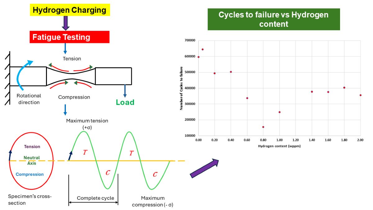
2.3. Fatigue Testing
Immediately after cathodic charging, each sample was tested under cyclic loading with a constant but alternating tensile and compressive loads (Figure 2) on top and bottom surfaces of samples respectively. The load, which was applied at the free end was calculated based on 50% of material’s yield strength known from preceding experiment with respect to the standard bending equations for specimen as a circular cross-section cantilever given in equation 1 below. Cyclic loading on samples was done using TecQuiment’s Rotating fatigue machine (SM1090V-Nottingham, UK). This equipment functions based on Wohler’s test [31,32]. Samples were subjected to cantilever loading as shown in Figure 3. It has a main unit, and a separate control and instrumentation unit (Figure 4 and Figure 5).
Where l is the distance from the midpoint of the sample to the end where load is applied, F is the applied load, D is the minimum neck area diameter, and σ is the applied stress.
The main unit rotates the sample under applied constant load as its motor turns a coupling and driveshaft which turns a collect chuck. The chuck grips the end of the test sample with uniform pressure around its circumference. The gimbal assembly houses a self-aligning bearing which rotates together with the free end of the test specimen (Figure 4a, b). Counting of the number of cycles (rotations) and the measurement of the applied load are respectively done by an embedded sensor and a load cell. It is also equipped with a safeguard cover which stops the test automatically when opened.
The instrumentation unit allows the control of the rotating speed of the specimen (Figure 5a, b). It also displays the applied testing conditions; frequency and load as well as the instantaneous number of cycles.
A constant frequency of 60Hz was applied for all samples hence, the exposure of samples to cyclic loading remained unchanged implying that any changes in fatigue behavior were primarily due to changes in material properties rather than external loading conditions.
3. Results and Discussion
3.1. Microstructure
The XRD analysis conducted on samples revealed a matching pattern of peaks with the characteristic peaks defined in the powder diffraction file (PDF) number as given in Figure 6. This matching pattern indicates that the major constituent of the samples is alpha ferrite having a BCC crystal structure as expected. Its presence as the major constituent hints that the samples have a microstructure predominantly composed of ferrite.
The Rockwell hardness test conducted on cold-finished mild steel sample resulted in a hardness value of 91.91 HRB. The obtained hardness value is relatively high as compared to general mild steel, indicating substantial work hardening due to the cold-finishing process of these samples. The cold-finishing process refines the grain structure and increases dislocation density within the steel resulting in work hardening, which significantly increases the material's hardness.
The metallographic analysis conducted under SEM revealed a microstructural composition characterized by homogeneous distribution of distinct pearlite and ferrite grains (Figure 7). The average ferrite grain size is about 15 µm, while pearlite is only 3 µm
In addition to the grain structure, the SEM images also showed the presence of inclusions within the material. Inclusions are foreign particles or impurities that are trapped within the grains or at the grain boundaries. These inclusions might have originated from various sources, such as the raw materials, the manufacturing process, or environmental contamination and can greatly impact material properties by acting as stress concentrators, which may initiate cracks and reduce overall strength and durability.
EDX point analysis was conducted on three distinct inclusions observed on the sample's surface as well as other points and regions of the steel matrix. A total of ten distinct locations were examined for clarity and ample understanding of the sample's elemental composition. The analysis was systematically divided into two parts: point analysis and region analysis. The first seven locations, designated as Points 1 through 7, were analyzed at specific points to determine the elemental composition at those precise locations. The remaining three locations, labeled as regions 8 through 10, involved broader region analyses to capture the overall elemental distribution within larger areas of the sample. The analysis revealed a high count of sulfur and manganese (Table 2) at all the examined inclusion particles (points 1-3) as given in Figure 8. This suggests that the particles are likely MnS slag that typically form during the processing of the steel.
The thorough examination of the general material surface revealed that the matrix is composed of ferrite with some pearlite, a microstructural feature consisting of alternating layers of soft and ductile ferrite (α-iron) and brittle and hard cementite (Fe₃C) whose combination give good strength and toughness situated at the ferrite grain boundaries.
In the EDX analysis, points 4 to 7 at the grain boundaries exhibited relatively higher carbon content and reduced ferrite, suggesting the presence of the pearlite phase. In contrast, the regions (8 to 10) analyzed within the grains showed a high content of ferrite, indicating that the grains are primarily composed of ferrite.
The dominance of ferrite in the material further confirms the results obtained from the XRD analysis.
3.2. Fatigue Response to Varying Hydrogenating Conditions
Based on the findings of this study, the behavior of test samples under different hydrogenating conditions revealed an elaborate relationship between hydrogen permeation and the material's fatigue life. Initially, as hydrogen permeation increases, the number of cycles to failure decreases, indicating a reduction in the material's resistance to cyclic loading. However, at higher hydrogen contents, the reverse occurred as the number of cycles to failure began to increase as shown in Figure 9.
In general, when hydrogen atoms diffuse into the steel lattice and defect sites such as grain boundaries, vacancies, interstitials and dislocations, they interact with their surroundings and cause significant change in the mechanical properties of the steel. The variation in the number of cycles to failure of mild steel under different hydrogenating conditions can be explained by considering the mechanistic effects of HE, HEDE [2,33], and HELP [16,17] on the material, as a result, the number of cycles to failure decreases and increases as observed at varying hydrogen contents.
At low to moderate hydrogen concentration, ranging from 0.05 to 0.80wppm, as the hydrogen content increases fatigue life drops (Figure 9). This behavior can be attributed to a phenomenon termed HEDE [34,35,36], a mechanism that significantly contributes to the reduction in the fatigue life of hydrogen-charged mild steel samples. This phenomenon occurs due to the presence of hydrogen atoms within the steel's microstructure, which weakens the bonds between atoms and grains, leading to premature failure.
Exposure of mild steel samples to hydrogen through electrochemical hydrogen charging causes hydrogen atoms to diffuse into the steel's microstructure. The diffusion primarily occurs along grain boundaries, dislocations, and other microstructural defects. Once inside the steel, hydrogen atoms tend to localize at regions of high stress and strain concentration, such as grain boundaries, crack tips, and other microstructural imperfections. The presence of hydrogen atoms at these locations weakens the metallic bonds between iron atoms by reducing the cohesive strength of the material. This weakening occurs for the reason that hydrogen atoms create additional tensile stress [29,34] within the lattice structure, making it easier for bonds to break under applied stress. The weakened bonds due to hydrogen atoms make the material more prone to crack initiation. Under cyclic loading conditions, as experienced during fatigue testing, these weakened regions are more likely to develop micro-cracks. The presence of hydrogen accelerates the formation of these cracks, reducing the number of cycles required for crack initiation.
Once a crack is initiated, the hydrogen atoms continue to assist in the propagation of the crack by further weakening the bonds at the crack tip. This process, known as hydrogen-enhanced crack growth [35,36], leads to faster crack propagation rates compared to hydrogen-free conditions. The reduction in cohesive strength at the crack tip allows the crack to grow with lower applied stress, thereby accelerating the overall failure process. The combined effect of accelerated crack initiation and faster crack propagation due to HEDE results in a significant reduction in the fatigue life of the hydrogen-charged samples. The material fails after fewer cycles of loading compared to samples not exposed to hydrogen, indicating a reduction in fatigue resistance.
At higher hydrogen concentrations, ie. 0.80 to 2.00wppm, HELP takes over. Through HELP mechanism, hydrogen facilitates dislocations motion within the crystal lattice by reducing the interaction energy and resistance from the lattice and other obstacles. Hence, the diffused hydrogen atoms cause localized plastic deformation. As dislocations move more easily in the presence of hydrogen, they can concentrate in specific regions rather than being uniformly distributed throughout the material. The enhanced dislocation mobility leads to localized areas of intense plastic deformation as dislocations tend to accumulate and move in specific paths where the barriers are lowest, creating regions of high strain. This implies that instead of the stress being distributed evenly throughout the material, it becomes concentrated in specific areas where dislocations are more mobile [37,38]. This deformation leads to improved toughness and ductility, hence, increased HE resistance and enhanced fatigue life of the steel.
3.3. Analysis of Fracture Surfaces
3.3.1. Uncharged Specimen
Fracture surface analysis of the uncharged (0.00wppm) sample under SEM revealed dimpled surface with few microcracks and microvoids as shown in Figure 10.
During cyclic loading, stress concentrations arise around inclusions, second-phase particles, scratches, notches, pits, inclusions and other microstructural inhomogeneities within the material. These sites are favorable for the nucleation of microvoids. Dislocations pile up around these particles and inclusions, generating high local stresses that promote microvoid nucleation. As cyclic loading continues, these nucleated microvoids begin to grow due to the applied cyclic stress causing plastic deformation around the voids. This plastic deformation leads to the expansion of microvoids, which eventually grow and coalesce with neighboring voids. The coalescence of these microvoids forms larger voids, reducing the effective load-bearing area of the material.
Coalesced microvoids result in the formation of a characteristic dimpled pattern on the fracture surface. Each dimple corresponds to the site of a microvoid that has grown and merged with others. When a critical density of microvoids is reached, the remaining unfractured ligament of material between the voids can no longer sustain the applied stress. This leads to the rapid propagation of the crack through the remaining material.
The final rupture occurs in a ductile manner, characterized by extensive plastic deformation and energy absorption. This process leads to the formation of the observed dimpled fracture surface, appearing as rounded, crater-like depressions. The size and distribution of these dimples enable understanding into the nature of the material and the conditions under which it failed. Larger dimples typically indicate sites where larger inclusions or second-phase particles were present, while smaller dimples indicate more homogeneous regions of the material.
3.3.2. Moderately Charged Samples
The analysis of fractured surfaces of samples charged with relatively lower hydrogen contents (ie. 0.05, 0.20, 0.40wppm) revealed a combination of ductile and brittle fatigue features (Figure 11). This phenomenon can be explained by the interaction between HE mechanisms and the inherent properties of the material. At lower hydrogen charging levels, the distribution of hydrogen within the material may be uneven. As a result, regions with higher hydrogen concentrations exhibit more brittle behavior, while other areas retain the material’s inherent ductility.
In brittle regions, the fracture surface displays cleavage facets, characterized by flat, smooth surfaces (Figure 11b,d). These facets form when cracks propagate rapidly through the crystal planes with minimal plastic deformation. The brittle characteristics observed as cleavage facets and microcracks on the fracture surfaces of hydrogen-charged materials are directly linked to the HEDE mechanism as above-mentioned. Hydrogen atoms adsorb and diffuse into the material, accumulating at stress concentration sites such as grain boundaries or dislocation cores. This accumulation of hydrogen reduces the cohesive strength of atomic bonds within the material, making it easier for these bonds to break under stress. The weakened cohesive strength causes the separation of atomic planes at stresses lower than would be required in the absence of hydrogen.
The presence of hydrogen atoms particularly weakens atomic bonds at grain boundaries and other defects, leading to the initiation of microcracks. These microcracks can rapidly grow and coalesce, forming larger cracks. The weakened bonds also cause cracks to propagate along specific crystallographic planes, resulting in the appearance of cleavage facets on the fracture surface. The combination of cleavage facets and microcracks indicates a brittle fracture mode, driven by the HEDE mechanism. This results in the material fracturing with minimal plastic deformation, exhibiting pronounced brittle behavior. Additionally, brittle fractures can manifest as transgranular cracks, where the crack propagates through the grains rather than along the grain boundaries.
Contrarywise, in areas less affected by hydrogen diffusion, the fatigue fracture surface exhibits ductile topographies, as discussed in Section 3.3.1.
3.3.3. Highly Charged Samples
For samples charged with relatively high hydrogen contents (1.60, 1.80, and 2.00wppm), analysis of the fracture surfaces exhibited distinct features that differ significantly from those observed in uncharged and moderately charged samples.
The observation of cleavage facets, macrocracks, secondary cracks, and striations in highly hydrogen-charged materials can be attributed to the HELP mechanism. Hydrogen atoms enhance dislocation mobility, leading to localized plastic deformation (i.e., work-hardening) that concentrates stress, facilitates crack initiation and propagation, and results in the dense fracture surface features observed.
Hydrogen atoms diffuse into the material and accumulate at dislocation cores and grain boundaries, reducing the energy barrier for dislocation motion. This leads to increased dislocation activity and localized plastic deformation, creating regions of high internal stress, particularly at dislocation pile-ups. These high-stress regions initiate cracks more easily due to the presence of hydrogen, which weakens atomic bonds. Cracks propagate along cleavage planes where atomic bonds are weaker, facilitated by the presence of hydrogen. The rapid propagation of cracks along these planes results in the formation of cleavage facets (Figure 12b) on the fracture surface, indicating a brittle fracture mode.
The presence of hydrogen accelerates the fatigue crack growth rate and enhances the brittleness of the material, making cleavage the dominant fracture mode under the given experimental conditions.
Observed striations (Figure 12c) are indicative of incremental crack growth under cyclic loading. They appear as fine, parallel lines perpendicular to the direction of crack propagation. In the context of HE and HELP, striations form due to repeated cycles of localized plastic deformation and crack advancement. Hydrogen enhances the mobility of dislocations, leading to cyclic plastic deformation at the crack tip. Under fatigue loading, samples also experience repeated application and removal of stress, which leads to the initiation and propagation of fatigue cracks. Each cycle of loading causes a small, incremental advancement of the crack front whose growth rate is accelerated by the presence of diffused hydrogen. Hydrogen enhances the ease with which cracks initiate by weakening the metal at the crack tip. The crack propagates in a stepwise pattern with each load cycle, leaving behind striations on the fracture surface. Each striation corresponds to one complete load cycle. The presence of diffused hydrogen makes striations more prominent due to the increased crack growth rate and more brittle nature of the fracture process.
Additionally, high-stress regions resulting from dislocation pile-ups through HELP mechanism initiate microcracks more easily at stress concentrators such as surface imperfections, inclusions (Figure 12d), or grain boundaries due to the presence of hydrogen, which weakens atomic bonds. Under applied external stress, such as cyclic loading, microcracks propagate and coalesce, with hydrogen reducing resistance to crack growth. This coalescence reduces the effective load-bearing cross-section of the material, increasing the local stress further. Under continued cyclic loading, these coalesced cracks propagate in a brittle manner, often along specific crystallographic planes or grain boundaries. Once the microcracks have coalesced sufficiently, they form a dominant macrocrack that propagates through the material as shown in Figure 12a above. This macrocrack grows with each loading cycle, driven by the high stress intensity at its tip. The macrocrack grows to a critical size where the remaining cross-sectional area can no longer support the applied load, leading to sudden catastrophic failure. The formation of macrocracks causes stress redistribution, creating new regions of high stress around the main crack. These new high-stress regions initiate secondary cracks due to localized plasticity and weakened atomic bonds which propagate and contribute to the overall fracture.
The crack propagates through the grains in a brittle manner, often leaving behind steps or ledges. The surface shows sharp, stepped features that indicate brittle transgranular fracture (Figure 12b), with no evidence of plastic deformation. As already mentioned above, reduction in bond strength makes it easier for cracks to propagate through the grains rather than along the grain boundaries. Also, in instances where grains contain trapping sites for hydrogen such as voids, the cracks propagate transgranularly as grains themselves are embrittled by hydrogen.
EDX analysis was conducted at the three distinct points on the inclusions observed on the fracture surface of the 1.80wppm charged sample, as illustrated in Figure 12d, to determine the elemental composition at these locations. Analyzed points are highlighted in Figure 13 below.
The EDX spectrum at the first point exhibited the highest count for sulfur (S). This significant presence of sulfur indicates that the inclusion at this location is likely sulfide-based. Sulfide inclusions are common in steel and can form compounds such as manganese sulfide (MnS) or iron sulfide (FeS). The high sulfur content suggests the presence of MnS or FeS inclusions, which are known to affect the material's fracture behavior and mechanical performance.
At the second point, the EDX analysis showed the highest count for manganese (Mn). The elevated manganese content, when considered alongside the sulfur detected at Point 1, further supports the possible presence of manganese sulfide (MnS) inclusions. Manganese sulfide inclusions are typical in steel and can have a notable impact on its mechanical properties, particularly its ductility and toughness. The detection of high manganese levels at this point confirms the likelihood of MnS inclusions contributing to the observed fracture characteristics.
The EDX spectrum at the third point revealed the highest count for iron (Fe). This suggests that the region of the inclusion at this point has a higher concentration of iron. The high iron content may imply a transition zone from the inclusion to the surrounding steel matrix or the presence of iron-rich phases within the inclusion itself. This transition could signify the interaction between the inclusion and the steel matrix, which can influence the fracture mechanics and overall structural integrity of the material.

Table 4.
Summary of elemental net counts on inclusions on 1.8wppm charged sample.
| Net Counts | |||
| Element | Point 1 | Point 2 | Point 3 |
| C | 15100 | 1923 | 1281 |
| F | 0 | 0 | 0 |
| S | 220886 | 6126 | 781 |
| Mn | 95305 | 51447 | 11177 |
| Fe | 11571 | 17232 | 21256 |
| Si | 0 | 175 | 0 |
4. Conclusions
- This study on the fatigue behavior of cold-finished mild steel under varying conditions of hydrogen charging has provided substantial understandings into the material's response to hydrogen permeation.
- The experimental results established that the number of cycles to failure initially decreased with increasing hydrogen concentration, dropping from 596,057 cycles for uncharged samples (0.00 wppm) to 154,925 cycles at an intermediate hydrogen concentration (0.80wppm). This decline highlights the damaging impact of hydrogen embrittlement, which accelerates fatigue crack initiation and propagation.
- Interestingly, at very high hydrogen concentrations, the number of cycles to failure showed an unexpected increase in number of cycles to failure of 249,775 for 1.00wppm through to 355,407 for 2.00wppm.
- This suggests the presence of a threshold beyond which additional hydrogen may alter the dominant fatigue mechanisms, possibly due to changes in crack propagation behavior or the saturation of hydrogen-related defects and mechanisms such as HELP and HEDE.
Author Contributions
E.S.: Writing initial draft, edit, Z.N.F.: Review, edit, supervision. All authors have read and agreed to the published version of the manuscript.
Funding
This research was funded by the Natural Sciences and Engineering Research Council of Canada (NSERC), grant number RGPIN 05125-17.
Data Availability Statement
The original contributions presented in the study are included in the article, further inquiries can be directed to the corresponding author.
Conflicts of Interest
The authors declare no conflict of interest.
References
- Nagao, A.; Dadfarnia, M.; Somerday, B.P.; Sofronis, P.; Ritchie, R.O. Hydrogen-Enhanced-Plasticity Mediated Decohesion for Hydrogen-Induced Intergranular and “Quasi-Cleavage” Fracture of Lath Martensitic Steels. J. Mech. Phys. Solids 2018, 112, 403–430. [Google Scholar] [CrossRef]
- Troiano, A.R. The Role of Hydrogen and Other Interstitials in the Mechanical Behavior of Metals. Metallogr. Microstruct. Anal. 2016, 5, 557–569. [Google Scholar] [CrossRef]
- Li, X.; Liu, C.; Wang, X.; Dai, Y.; Zhan, M.; Liu, Y.; Yang, K.; He, C.; Wang, Q. Effect of Microstructure on Small Fatigue Crack Initiation and Early Propagation Behavior in Super Austenitic Stainless Steel 654SMO. Int. J. Fatigue 2024, 179. [Google Scholar] [CrossRef]
- Brem, J.C.; Barlat, F.; Dick, R.E.; Yoon, J.-W. Characterizations of Aluminum Alloy Sheet Materials Numisheet 2005.; United States, 2005; Vol. 778.
- Xue, Y.; Solanki, K.; Steele, G.; Horstemeyer, M.; Newman, J. Quantitative Uncertainty Analysis for a Mechanistic Multistage Fatigue Model. In. 2012,. [CrossRef]
- Park, J.Y.; Park, Y.C.; Kim, H.-K. A Methodology for Fatigue Reliability Assessment Considering Stress Range Distribution Truncation. Int. J. Steel Struct. 2018, 18, 1242–1251. [Google Scholar] [CrossRef]
- Huffman, P.J.; Correia, J.A.F.O.; Mourão, A.; Bittencourt, T.; Calçada, R. Predicted Distribution in Measured Fatigue Life from Expected Distribution in Cyclic Stress–Strain Properties Using a Strain-Energy Based Damage Model. In Proceedings of the Structural Integrity and Fatigue Failure Analysis; Lesiuk, G., Szata, M., Blazejewski, W., Jesus, A.M.P. de, Correia, J.A.F.O., Eds.; Springer International Publishing: Cham, 2022; pp. 65–71. [Google Scholar]
- Koster, M.; Lis, A.; Lee, W.J.; Kenel, C.; Leinenbach, C. Influence of Elastic–Plastic Base Material Properties on the Fatigue and Cyclic Deformation Behavior of Brazed Steel Joints. Int. J. Fatigue 2016, 82, 49–59. [Google Scholar] [CrossRef]
- Čanžar, P.; Tonković, Z.; Kodvanj, J. Microstructure Influence on Fatigue Behaviour of Nodular Cast Iron. Mater. Sci. Eng. A 2012, 556, 88–99. [Google Scholar] [CrossRef]
- Ponson, L.; Bonamy, D. Crack Propagation in Brittle Heterogeneous Solids: Material Disorder and Crack Dynamics. In Proceedings of the IUTAM Symposium on Dynamic Fracture and Fragmentation; Ravi-Chandar, K., Vogler, T.J., Eds.; Springer Netherlands: Dordrecht, 2010; pp. 21–31. [Google Scholar]
- Song, S.W.; Kwon, Y.J.; Lee, T.; Lee, C.S. Effect of Al Addition on Low-Cycle Fatigue Properties of Hydrogen-Charged High-Mn TWIP Steels. Mater. Sci. Eng. A 2016, 677, 421–430. [Google Scholar] [CrossRef]
- Chen, X.; Ma, L.; Xie, H.; Zhao, F.; Ye, Y.; Zhang, L. Effects of External Hydrogen on Hydrogen-Assisted Crack Initiation in Type 304 Stainless Steel. Anti-Corros Methods M. 2020, 67, 331–335. [Google Scholar] [CrossRef]
- Pal, S.; Singh Raman, R.K. Determination of Threshold Stress Intensity Factor for Stress Corrosion Cracking (KISCC) of Steel Heat Affected Zone. Corros. Sci. 2009, 51, 2443–2449. [Google Scholar] [CrossRef]
- De Pannemaecker, A.; Fouvry, S.; Brochu, M.; Buffiere, J.Y. Identification of the Fatigue Stress Intensity Factor Threshold for Different Load Ratios R: From Fretting Fatigue to C(T) Fatigue Experiments. In Proceedings of the International Journal of Fatigue; Elsevier Ltd, January 1 2016; Vol. 82; pp. 211–225. [Google Scholar]
- Kitahara, G.; Asada, T.; Matsuoka, H. Effects of Diffusible Hydrogen on Fatigue Life of Spot Welds in High-Tensile-Strength Steel Sheets. ISIJ Int. 2023, 63, 889–898. [Google Scholar] [CrossRef]
- Djukic, M.B.; Bakic, G.M.; Sijacki Zeravcic, V.; Sedmak, A.; Rajicic, B. The Synergistic Action and Interplay of Hydrogen Embrittlement Mechanisms in Steels and Iron: Localized Plasticity and Decohesion. Eng. Fract. Mech. 2019, 216. [Google Scholar] [CrossRef]
- Örnek, C.; Şeşen, B.M.; Ürgen, M.K. Understanding Hydrogen-Induced Strain Localization in Super Duplex Stainless Steel Using Digital Image Correlation Technique. Met. Mater. Int. 2022, 28, 475–486. [Google Scholar] [CrossRef]
- Neikter, M.; Colliander, M.; de Andrade Schwerz, C.; Hansson, T.; Åkerfeldt, P.; Pederson, R.; Antti, M.L. Fatigue Crack Growth of Electron Beam Melted TI-6AL-4V in High-Pressure Hydrogen. Materials 2020, 13. [Google Scholar] [CrossRef] [PubMed]
- Beachem, C.D. A New Model for Hydrogen-Assisted Cracking (Hydrogen “Embrittlement”);
- Lynch, S. Hydrogen Embrittlement Phenomena and Mechanisms. Corros. Rev. 2012, 30, 105–123. [Google Scholar] [CrossRef]
- Oag-bvg Independent Auditor’s Report | 2022 Reports of the Commissioner of the Environment and Sustainable Development to the Parliament of Canada Hydrogen’s Potential to Reduce Greenhouse Gas Emissions H 2.; 2022.
- Davis, M.; Okunlola, A.; Di Lullo, G.; Giwa, T.; Kumar, A. Greenhouse Gas Reduction Potential and Cost-Effectiveness of Economy-Wide Hydrogen-Natural Gas Blending for Energy End Uses. Renew. Sustain. Energy Rev. 2023, 171. [Google Scholar] [CrossRef]
- Si, X.; Lu, R.; Zhao, Z.; Yang, X.; Wang, F.; Jiang, H.; Luo, X.; Wang, A.; Feng, Z.; Xu, J.; et al. Catalytic Production of Low-Carbon Footprint Sustainable Natural Gas. Nat. Commun. 2022, 13. [Google Scholar] [CrossRef] [PubMed]
- Sun, T.; Shrestha, E.; Hamburg, S.P.; Kupers, R.; Ocko, I.B. Climate Impacts of Hydrogen and Methane Emissions Can Considerably Reduce the Climate Benefits across Key Hydrogen Use Cases and Time Scales. Environ. Sci. Technol. 2023. [CrossRef] [PubMed]
- Standard Guide for Preparation of Metallographic Specimens 1. [CrossRef]
- Designation: E407 − 07 (Reapproved 2015) ´1 Standard Practice for Microetching Metals and Alloys 1. [CrossRef]
- Standard Test Method for Rockwell Hardness of Plastics and Electrical Insulating Materials 1. [CrossRef]
- Designation: E18 − 20 Standard Test Methods for Rockwell Hardness of Metallic Materials 1,2. [CrossRef]
- Sey, E.; Farhat, Z.N. Evaluating the Effect of Hydrogen on the Tensile Properties of Cold-Finished Mild Steel. Crystals (Basel) 2024, 14, 529. [Google Scholar] [CrossRef]
- Li, Q.; Ghadiani, H.; Jalilvand, V.; Alam, T.; Farhat, Z.; Islam, M.A. Hydrogen Impact: A Review on Diffusibility, Embrittlement Mechanisms, and Characterization. Materials 2024, 17. [Google Scholar] [CrossRef]
- Lipski, A. Rapid Determination of the Wöhler’s Curve for Aluminum Alloy 2024-T3 by Means of the Thermographic Method. In Proceedings of the AIP Conference Proceedings; American Institute of Physics Inc., October 20 2016; Vol. 1780. [Google Scholar]
- Mlikota, M.; Schmauder, S.; Božić, Ž. Calculation of the Wöhler (S-N) Curve Using a Two-Scale Model. Int. J. Fatigue 2018, 114, 289–297. [Google Scholar] [CrossRef]
- Wasim, M.; Djukic, M.B.; Ngo, T.D. Influence of Hydrogen-Enhanced Plasticity and Decohesion Mechanisms of Hydrogen Embrittlement on the Fracture Resistance of Steel. Eng. Fail. Anal. 2021, 123, 105312. [Google Scholar] [CrossRef]
- Shibata, A.; Yonemura, T.; Momotani, Y.; Park, M.; Takagi, S.; Madi, Y.; Besson, J.; Tsuji, N. Effects of Local Stress, Strain, and Hydrogen Content on Hydrogen-Related Fracture Behavior in Low-Carbon Martensitic Steel. Acta. Mater. 2021, 210, 116828. [Google Scholar] [CrossRef]
- Matsunaga, H.; Takakuwa, O.; Yamabe, J.; Matsuoka, S. Hydrogen-Enhanced Fatigue Crack Growth in Steels and Its Frequency Dependence. Philos. Trans. R. Soc. A 2017, 375. [Google Scholar] [CrossRef] [PubMed]
- Traidia, A.; Chatzidouros, E.; Jouiad, M. Review of Hydrogen-Assisted Cracking Models for Application to Service Lifetime Prediction and Challenges in the Oil and Gas Industry. Corros. Rev. 2018, 36, 323–347. [Google Scholar] [CrossRef]
- Polyanskiy, V.A.; Belyaev, A.K.; Sedova, Yu.S.; Yakovlev, Yu.A. Mesoeffect of the Dual Mechanism of Hydrogen-Induced Cracking. Phys. Mesomech. 2022, 25, 466–478. [Google Scholar] [CrossRef]
- Gong, W.; Trtik, P.; Ma, F.; Jia, Y.; Li, J.; Bertsch, J. Hydrogen Diffusion and Precipitation under Non-Uniform Stress in Duplex Zirconium Nuclear Fuel Cladding Investigated by High-Resolution Neutron Imaging. J. Nucl. Mater. 2022, 570, 153971. [Google Scholar] [CrossRef]
Figure 1.
Illustrative diagram of specimen's dimensions (mm).
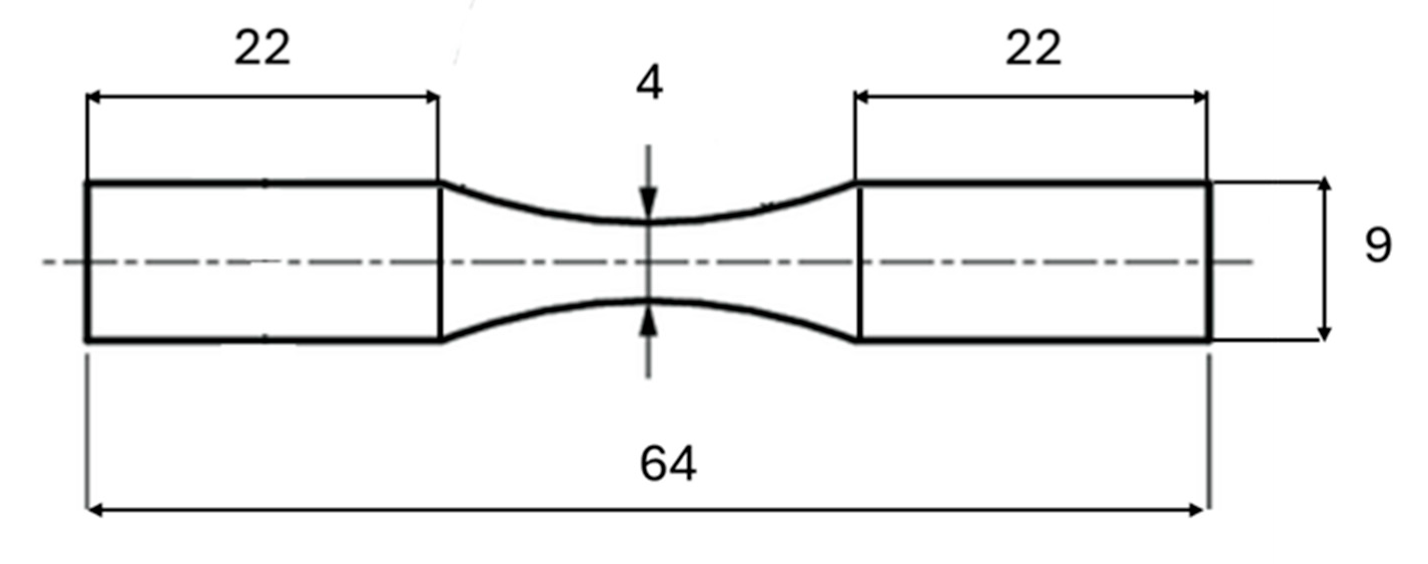
Figure 2.
Schematic representation of specimen cyclic loading mechanism.
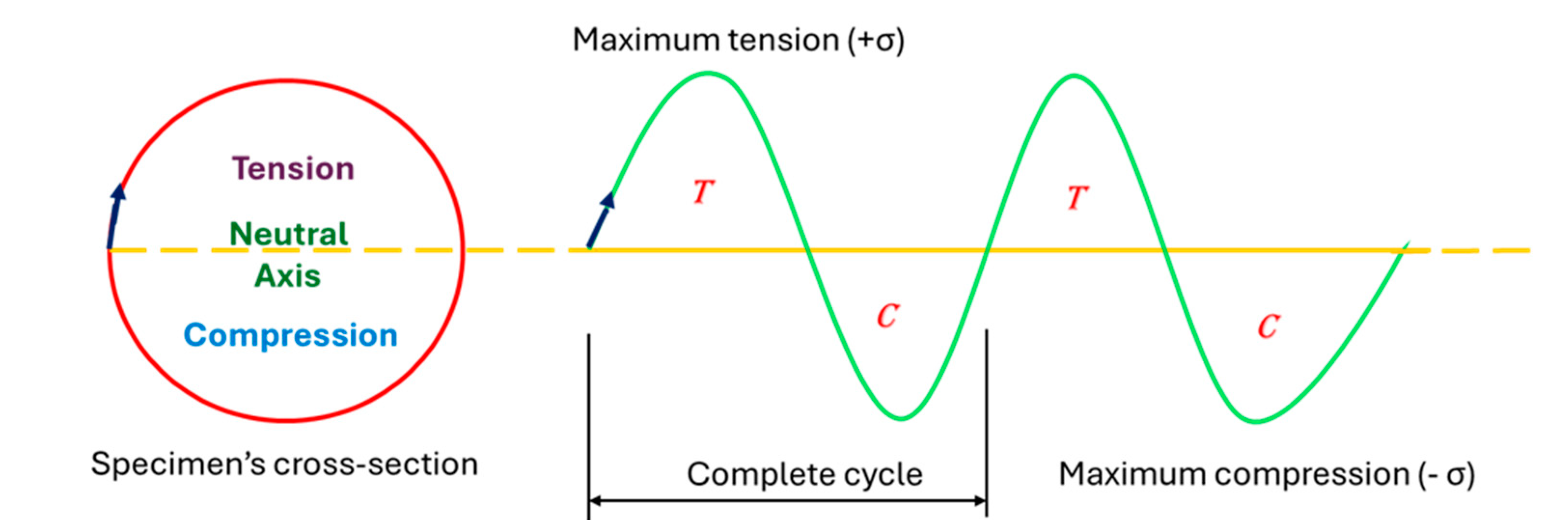
Figure 3.
Graphical illustration of rotating cantilever loading of specimen.
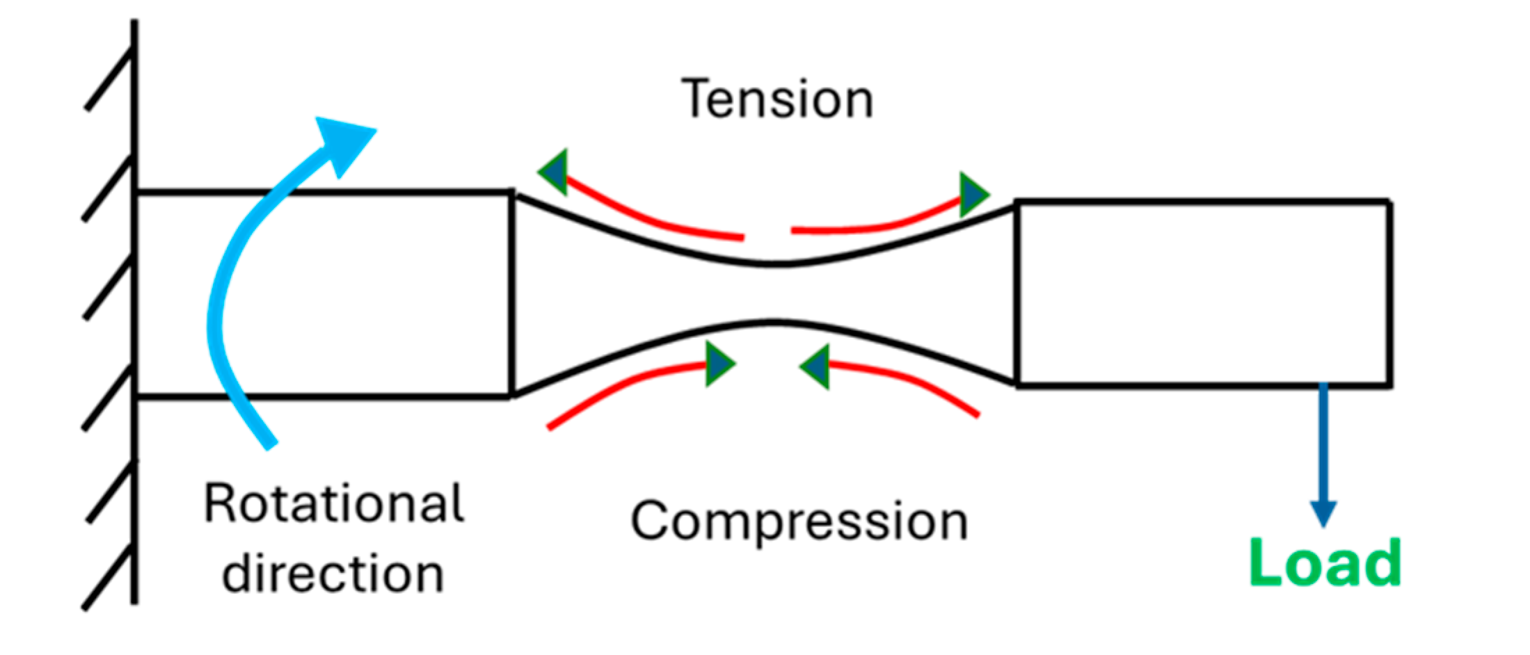
Figure 4.
Main Unit of fatigue testing set-up.
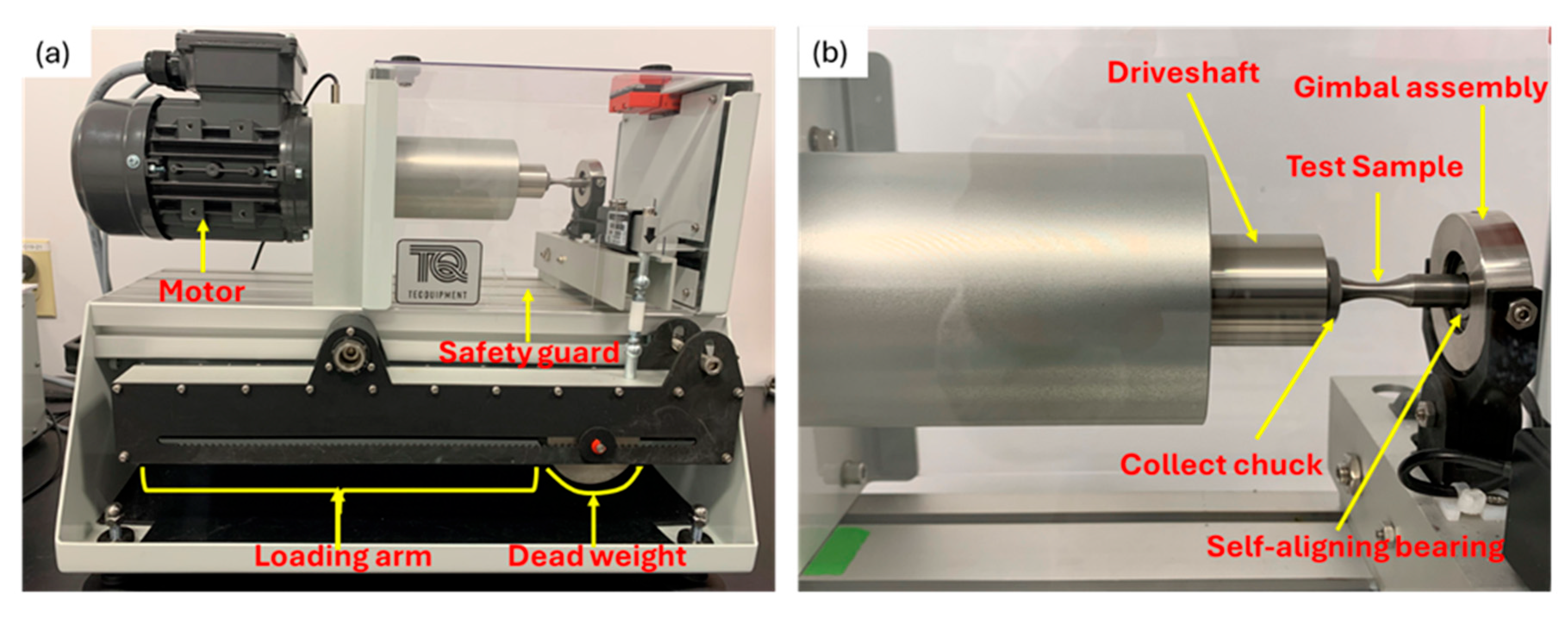
Figure 5.
Control and instrumentation Unit.
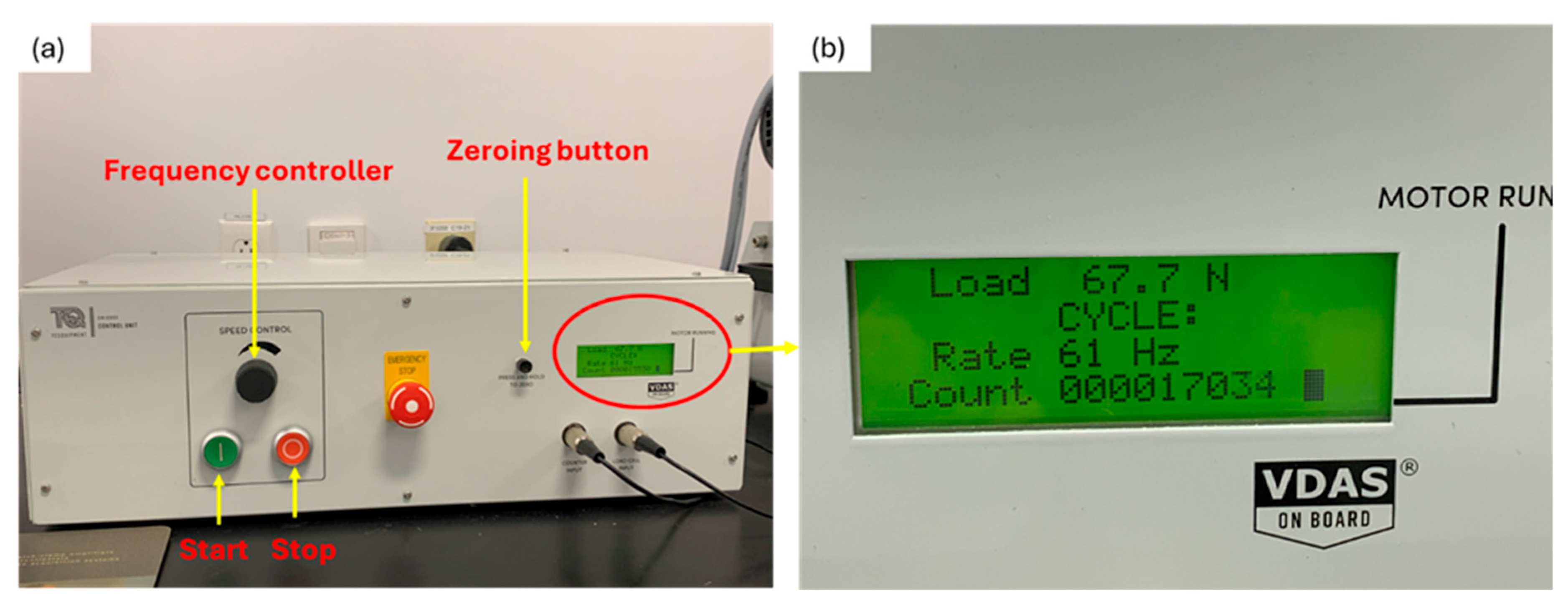
Figure 6.
X-Ray diffraction pattern of specimen.
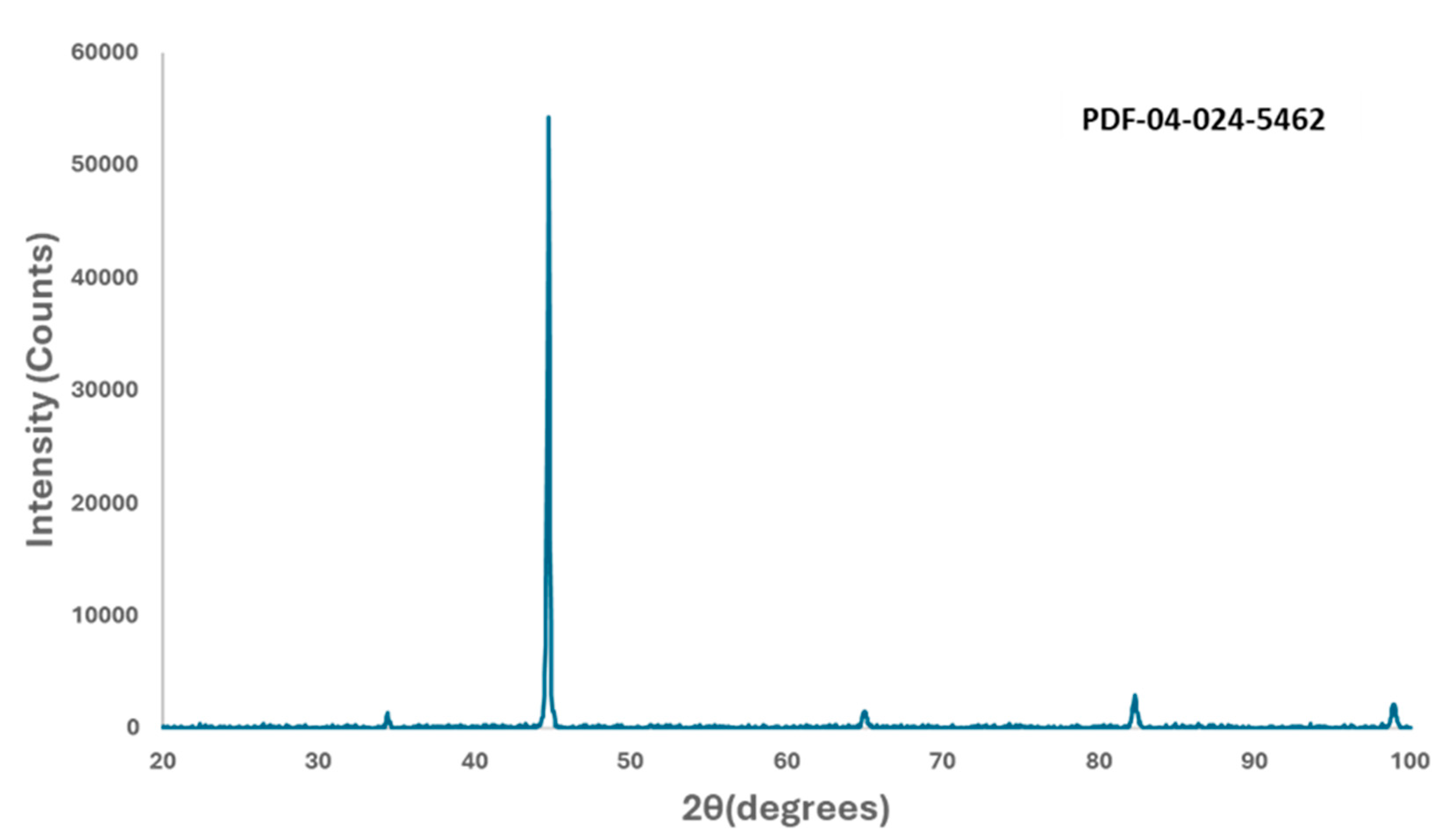
Figure 7.
SEM of the microstructural characteristics of the cold finished mild steel.
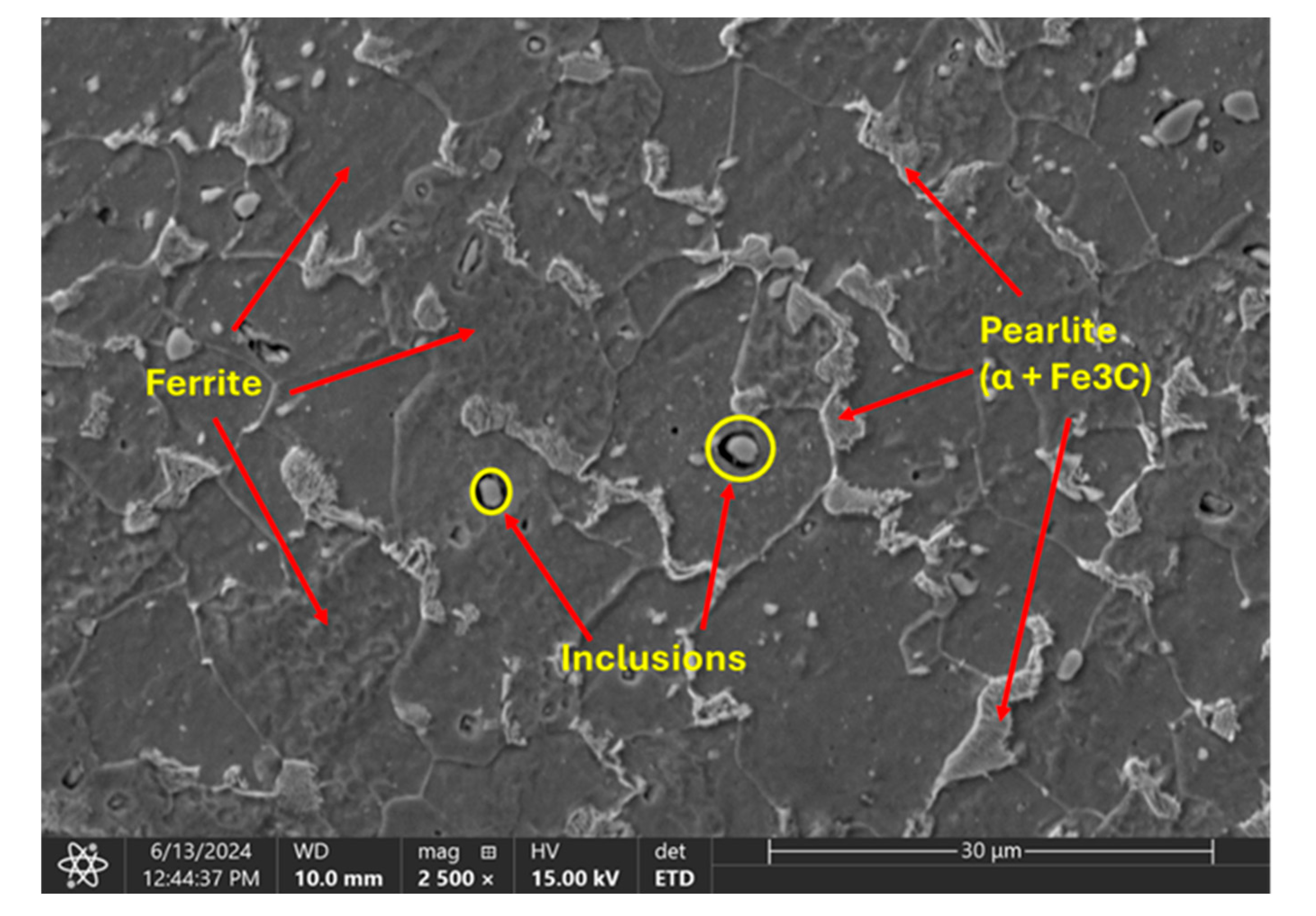
Figure 8.
Energy Dispersive X-ray Spectroscopy analysis of observed inclusions and steel matrix.
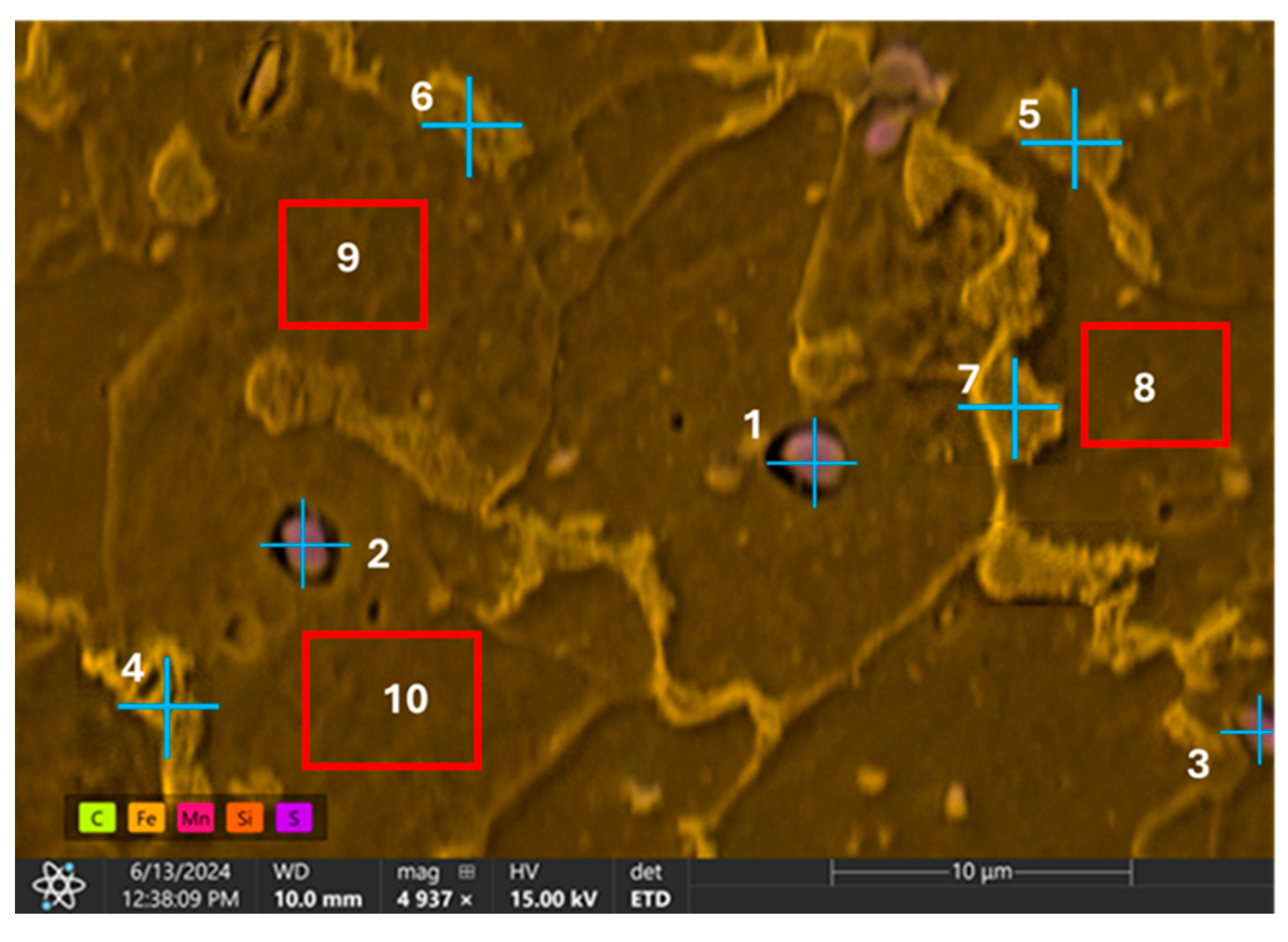
Figure 9.
Variation of number of cycles to failure with hydrogen content.
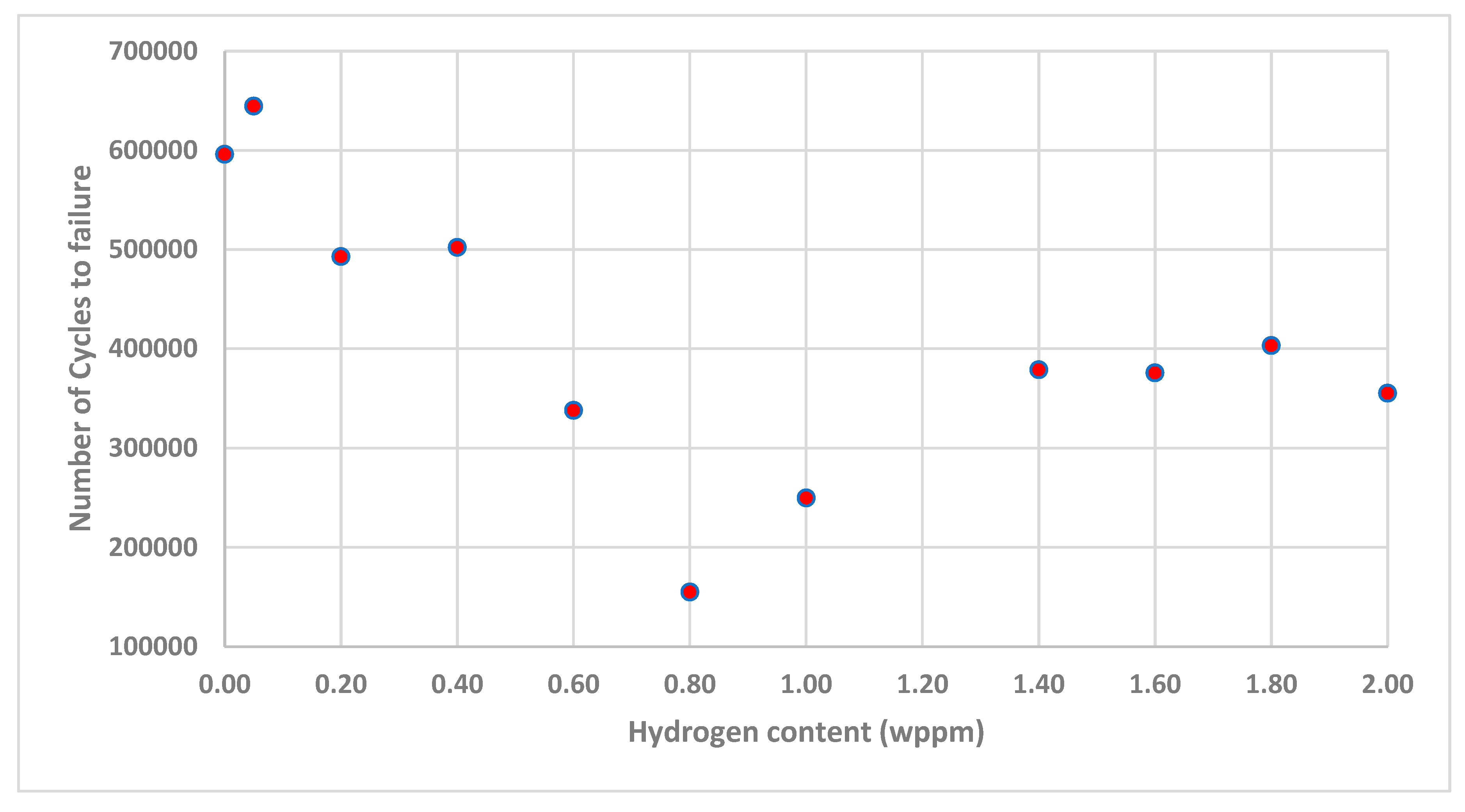
Figure 10.
SEM images of uncharged samples' surface (a) 500X (b) 1500X.
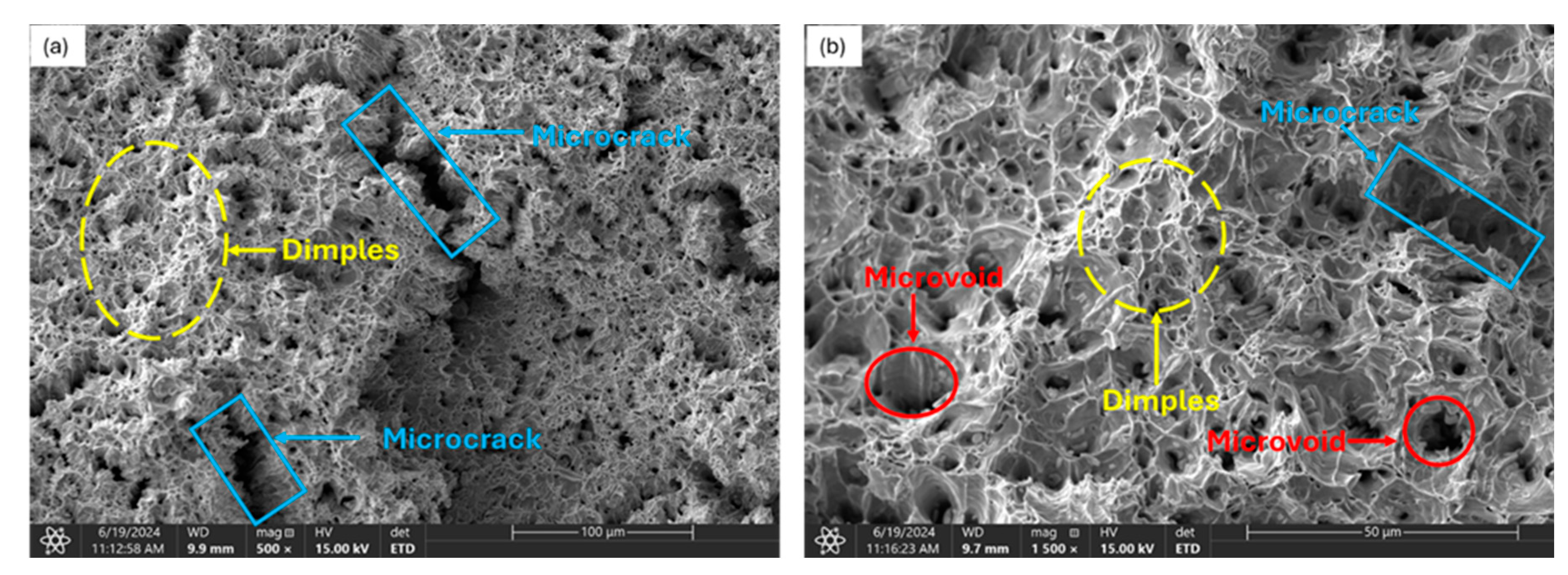
Figure 11.
Samples charged with low hydrogen content (a) 0.050wppm [500X] (b) 0.050 [2000X] (c) 0.200wppm [500X] (d) 0.200wppm (2000X].
Figure 11.
Samples charged with low hydrogen content (a) 0.050wppm [500X] (b) 0.050 [2000X] (c) 0.200wppm [500X] (d) 0.200wppm (2000X].
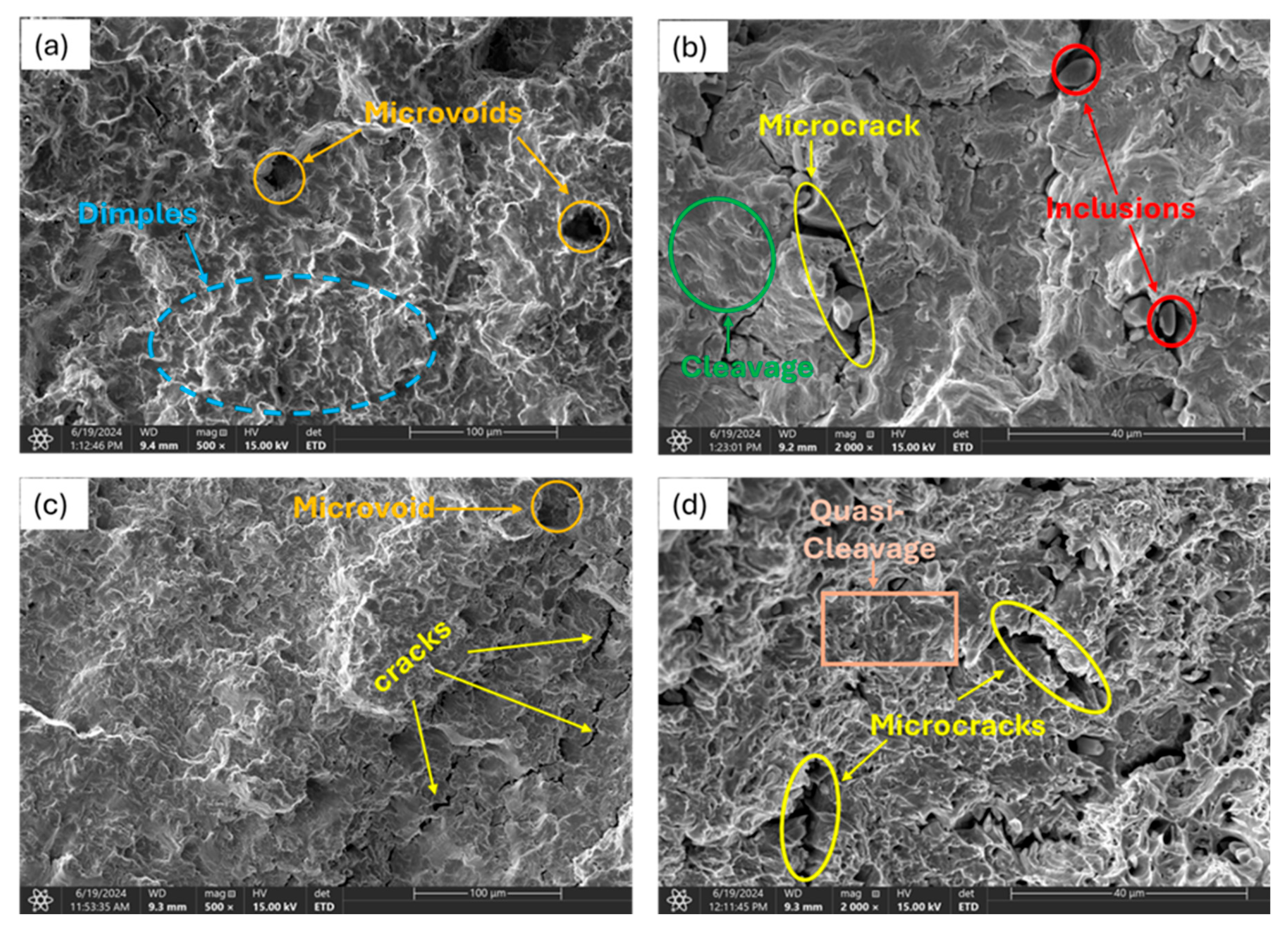
Figure 12.
Fracture surface of highly charged samples (a) 2.0wppm (1000X) (b) 2.0wppm (2005X) (c) 1.8wppm (500X) (d) 1.8wppm (1500X).
Figure 12.
Fracture surface of highly charged samples (a) 2.0wppm (1000X) (b) 2.0wppm (2005X) (c) 1.8wppm (500X) (d) 1.8wppm (1500X).
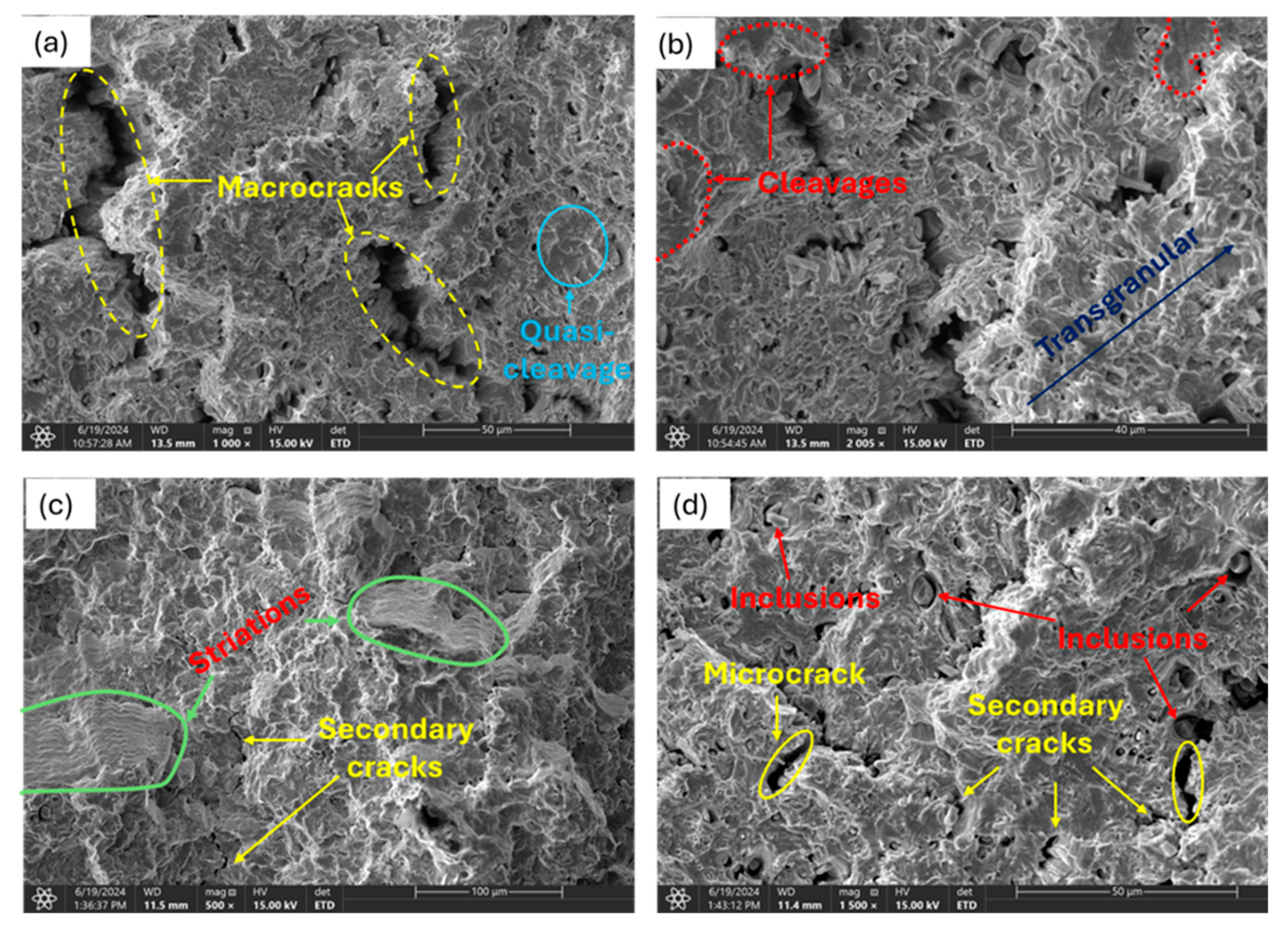
Figure 13.
EDX analysis of observed inclusion phases on 1.80wppm charged sample.
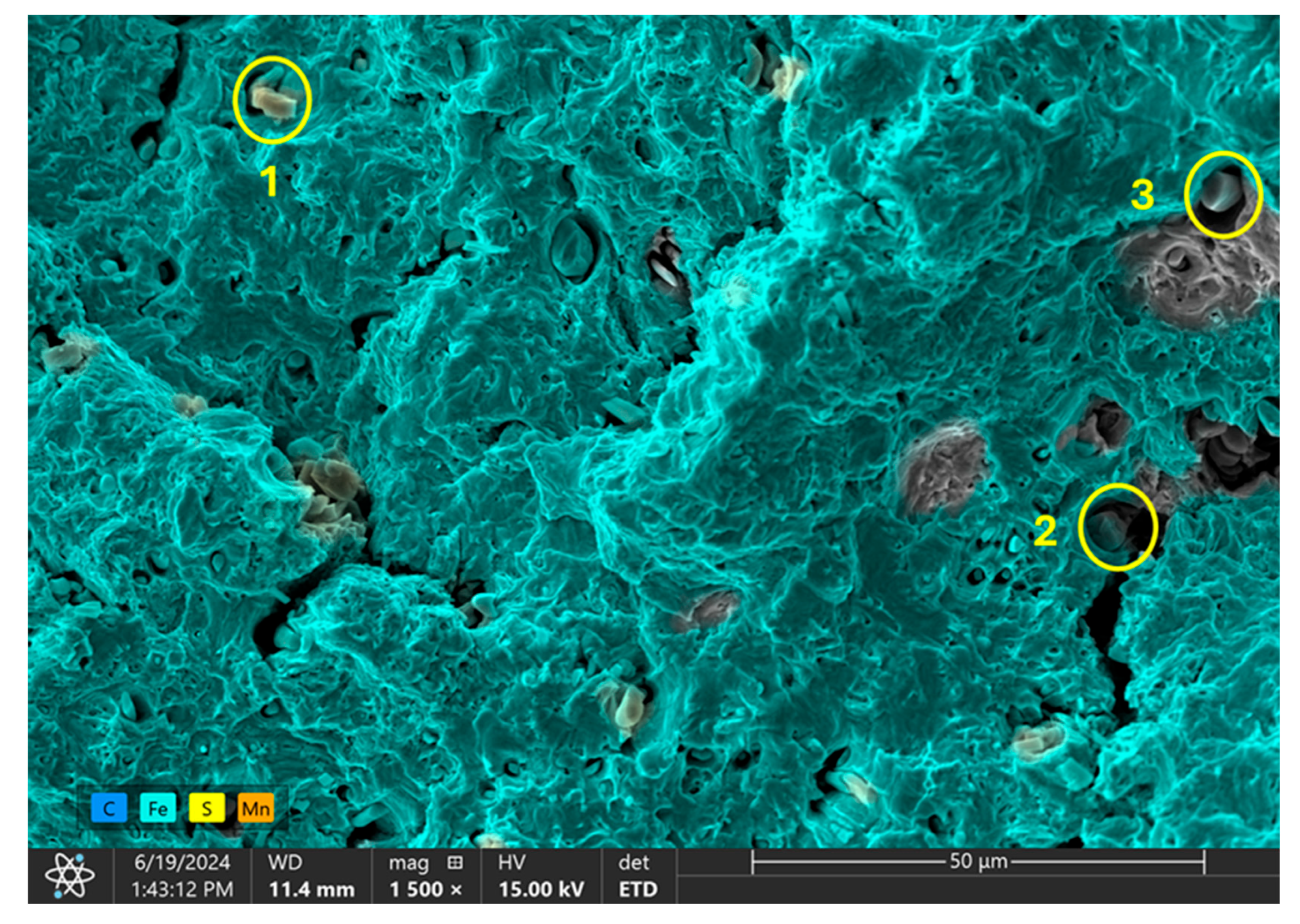
Table 1.
Chemical compositional outcome from ICP analysis.
| Element | Fe | C | Mn | Si | S | Cu | Ni | Cr |
| Composition (wt%) | 98.14 | 0.14 | 0.47 | 0.25 | 0.004 | 0.08 | 0.04 | 0.07 |
Table 2.
Summary of net counts for points analysis on observed inclusions on sample’s surface.
| Element | Point 1 | Point 2 | Point 3 |
|---|---|---|---|
| C | 17068 | 15750 | 19599 |
| Si | 3393 | 1731 | 1585 |
| S | 193066 | 181111 | 156222 |
| Mn | 89306 | 85520 | 75365 |
| Fe | 12081 | 16520 | 28773 |
Table 3.
Weight % of EDX analysis on ferrite matrix.
| Weight % | |||||||
| Element | Point 4 | Point 5 | Point 6 | Point 7 | Region 8 | Region 9 | Region 10 |
| C | 6.7 | 9.2 | 5.6 | 17.0 | 5.7 | 0.0 | 5.9 |
| Al | 0.0 | 0.0 | 0.0 | 0.0 | 0.0 | 0.0 | 0.0 |
| Si | 0.1 | 0.2 | 0.3 | 0.2 | 0.1 | 0.2 | 0.2 |
| S | 0.0 | 0.1 | 0.6 | 0.1 | 0.1 | 0.0 | 0.1 |
| Mn | 0.8 | 0.9 | 0.9 | 1.0 | 0.7 | 0.6 | 0.7 |
| Fe | 92.4 | 89.6 | 92.6 | 81.7 | 93.4 | 99.2 | 93.1 |
Disclaimer/Publisher’s Note: The statements, opinions and data contained in all publications are solely those of the individual author(s) and contributor(s) and not of MDPI and/or the editor(s). MDPI and/or the editor(s) disclaim responsibility for any injury to people or property resulting from any ideas, methods, instructions or products referred to in the content. |
© 2024 by the authors. Licensee MDPI, Basel, Switzerland. This article is an open access article distributed under the terms and conditions of the Creative Commons Attribution (CC BY) license (http://creativecommons.org/licenses/by/4.0/).
Copyright: This open access article is published under a Creative Commons CC BY 4.0 license, which permit the free download, distribution, and reuse, provided that the author and preprint are cited in any reuse.


