1. Introduction and Context
1.1. General Introduction
Bar and beam dynamics represents an interesting transition from the discrete harmonic model to the continuous acoustic and structural model. As such, the constitutive equations and their generic solutions - conditioned by boundary conditions - are a classic source of analytical development, which we propose to open up in two directions: the topological looping on the one hand, and the introduction of a point singularity on the other. Mathematically, this allows the closing of the system, and the introduction of a punctual perturbation in a continuous dynamic model.
As it turns, this analytical approach using elementary dynamic segments overlaps with a well-known biodynamic system that has been the subject of numerous numerical models, namely the semicircular canals that play a fundamental role in the inner ear, notably for measuring rotation rates. These are complex systems combining fluids (endolymph and perilymph), solids (bone and cartilage) and certain intermediate materials (cup).
Numerous numerical models of the semicircular canals have been proposed, providing a fairly convincing representation of endolymphic and perilymphic physiology. However, the disturbances induced by the main pathologies linked to the semicircular canals remain tricky to observe and model, which justifies the implementation of an analytical model, which is the subject of this article. Fundamentally, this type of model is relatively accurate, but its conceptual robustness offers the advantage of being able to introduce - at will - perturbations representing the influence of various pathological derangements. The proposed approach is therefore valid for modeling the sensitivity of pathologies on dynamic behavior.
The basic analytical models of semicircular canals generally consider rational, undeformable systems, based on the model of the rotating solid. We thus find the elementary inertial model constructed in rotation around a fixed inertial axis (Huyghens), then the motion of the fixed-point solid (Poinsot, Euler, Lagrange) and finally the gyroscopic extrapolation coupling the effects of precession and nutation (Poisson). In this article, on the other hand, the deformability of the system is taken into account. To remain in the analytical domain, theories of slender solid and fluid bodies are used. More specifically, the equations of bars and beams are exploited, giving the initial preference to the normal force approach, which we will qualify - in the context of beam theory - as a 1D approach.
In this longitudinal 1D approach - in the sense of bars and tubes - it should be noted that the elastic Hooke-Bresse equation - solid - and the Helmholtz equation - fluid - lead to a homogeneous d’Alembert equation based on propagation velocity - fluid and solid. The generic modal solutions are therefore harmonic and provide an algebraic framework for proposing various set-ups, representing both solid dynamics (longitudinal Lagrangian displacement) and fluid fluctuations (Eulerian pressure variations).
In the first stage, a simple topological loop is created; this closed bar - or ring in longitudinal mode - is the first element that enables us to recover the closed - physiological - vibroacoustic modes, and to experiment with a passive or active singularity. A passive singularity is a simple discontinuity in terms of displacement (in a Lagrangian representation) or pressure (in an Eulerian model). The active singularity consists in inverting the solution at a point (Möbius looping), introducing local retroactivity. It’s interesting to note that these two types of singularity have analogies with two types of pathology, windows and neuritis respectively.
The elementary model - which in fact constitutes a first qualitative approach - is then segmented, evoking the various anatomical parts in a fairly realistic way. A number of simplifications are proposed, concerning on the one hand the homogenization of moduli and on the other hand the introduction of a viscosity per segment on the wide parts of the canal.
Observation of the deterministic or chaotic nature of the generic solution then provides information on the consequences of the pathology, and the link with the singular boundary conditions gives clues to possible corrections. It should be noted that this topologically looped longitudinal 1D model provides a first approach to singular pathology, and opens the way to more advanced structural 1.5 models.
1.2. Medical Context
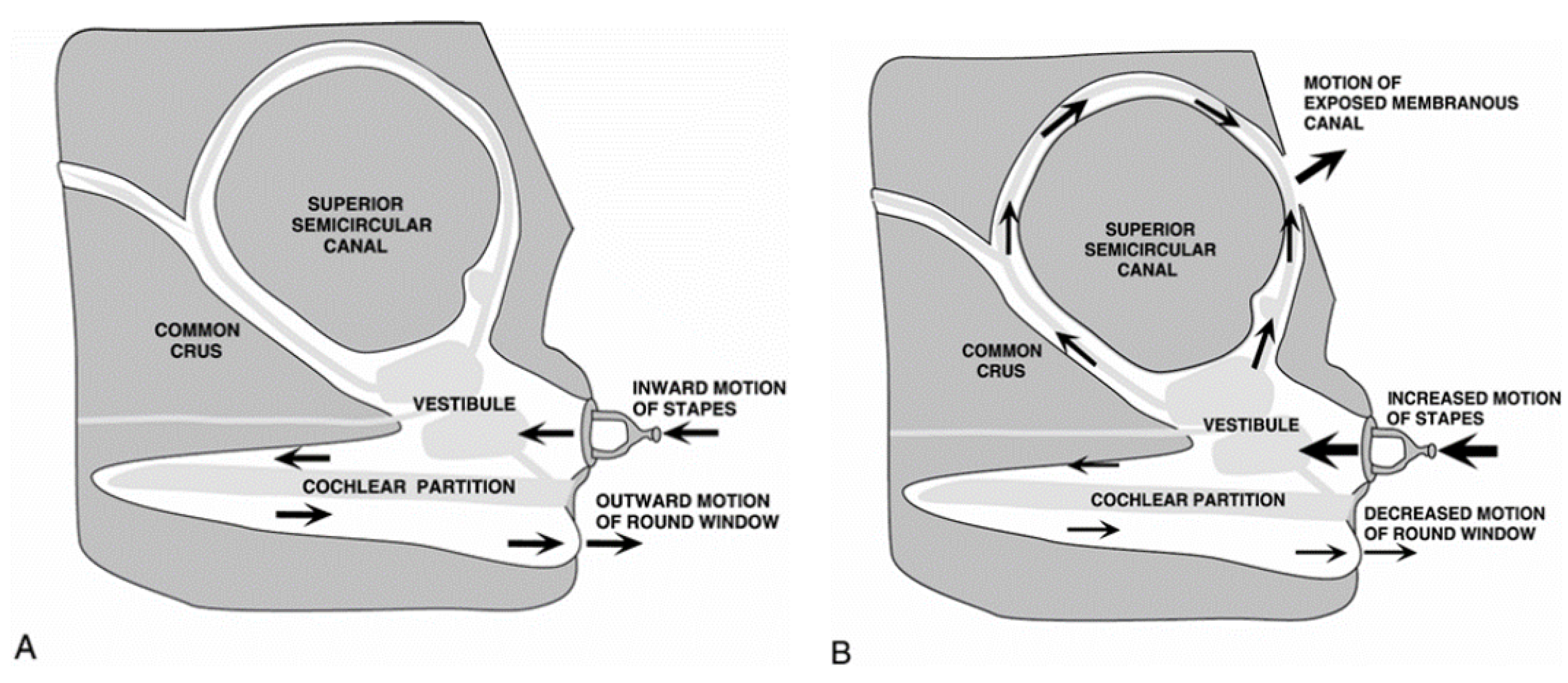
Under normal physiological conditions, sound is a mechanical wave that causes the tympano-ossicular complex to vibrate. Through the articulation between the stapes footplate and the oval window, sound is transmitted from the middle ear to the cochlea (1). The round window, on the other hand, is widely considered to be the anatomical structure that allows for pressure relief by releasing the mechanical energy provided by the ossicular chain to the labyrinthine fluid of the inner ear (2). Hearing encompasses the mechanisms that allow us to perceive the sound waves around us and is made possible by the conversion of these mechanical waves into nerve signals by the basilar membrane, which are then transmitted to the brain (3). Any pathologies or abnormalities in these structures (external, middle, and inner ears) and in the central auditory neural pathways can lead to hearing impairment. Minor was the first to describe, in 1998, a case series of sound- and/or pressure-induced vertigo in patients with superior semicircular canal dehiscence. The dehiscences were identified through computed tomographic scans, which revealed the absence of bone overlying the superior semicircular canal on the surface of the temporal bone (4). In addition to sound/pressure-induced vertigo, patients may experience air-conduction hearing loss observed at low frequencies with dehiscences larger than 3 mm. The significance of this air-bone gap is correlated with the size of the dehiscence (5). The most likely hypothesis is that the dehiscence acts as a "third window" in the inner ear, shunting acoustic energy away from the cochlea at low frequencies, thereby causing hearing loss (6). Some studies have attempted to understand the underlying biomechanical mechanism generating this shunt and have also tried to quantify it. One study specifically investigated the sound-induced displacement velocities of the stapes, umbo, and round window in a temporal bone bank using laser-Doppler vibrometry (6). These measurements were performed on healthy bones considered normal, on the same bones after creating a dehiscence in the superior semicircular canal, and also with the dehiscence patched. They found that the presence of a dehiscence in the superior semicircular canal led to a significant reduction in sound-induced round window velocity at low frequencies.
Figure 1.
Modeling semi-circular canals for a normal ear (figure extracted from the reference 18)
Figure 1.
Modeling semi-circular canals for a normal ear (figure extracted from the reference 18)
This allows us to better understand why there can be a air-bone gap result at low frequencies in the presence of a dehiscence, and also why patients might experience vertigo with loud sounds due to the shunting of acoustic energy toward the posterior labyrinth. Sound energy enters the inner ear via the oval window, causing fluid movement at the location of the bony defect. This generates propagating waves that subsequently lead to mechano-electrical transduction in the vestibular sensory organs through vibration and nonlinear fluid pumping (1). This same team also recorded changes in neural activity in the vestibular pathways in an animal model, evoked by auditory-frequency stimulation (1). Despite these findings, to our knowledge, no study currently exists to explain the purely biomechanical mechanism of the fluids, and this is what we aimed to address here.
2. Beam Closed Ring Model
2.1. Standard Beam Solutions
The aim of this section is to study the different resonance modes of a topologically closed beam. To this end, the equations of the dynamics of a rectilinear beam are retained and boundary closure conditions are applied. The beam’s radius of curvature is then neglected, which seems to be valid for a beam thickness that is negligible compared with the radius of curvature.
The equation verified by the longitudinal displacement in a rectilinear beam whose lateral shrinkage is neglected is given by :
where
and
E are respectively the density and the Young’s modulus of the material. This can be rewritten as :
2.2. Closed Ring Solution
The form of the general solution to the wave equation is valid whether the cross-section is constant or not (the material just has to be homogeneous; the solution can be obtained modally by separating the variables :
This general solution is of the form :
We then apply the following boundary conditions :
corresponding respectively to continuity in displacement and normal stress. This gives us the following system of equations :
2.3. Singularity
For the system to have a non-zero solution, its determinant must be zero. The various modes are therefore :
This corresponds to a system of standing waves.
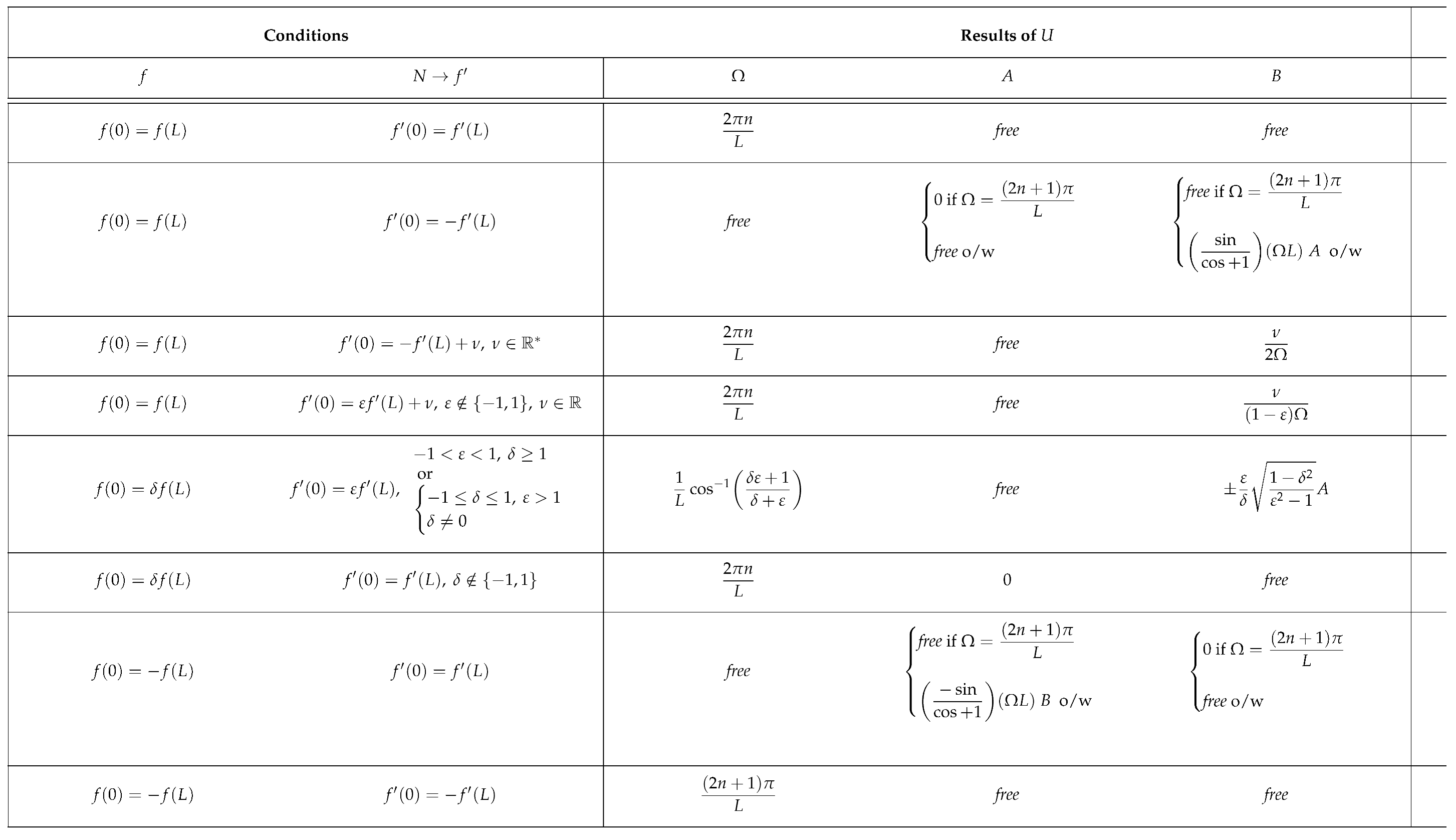
We then put together a number of solutions for different discontinuities in closure with the aim of modelling a pathology (see
Table 1). The term
free refers to the fact that any value of the given magnitude would satisfy the boundary conditions. You will find a representation of each case carried out with Julia on the
Figure 2. The amplitudes of the longitudinal displacements are plotted as transverse displacements for better visualisation. :
The first case in the table corresponds to the one we treated earlier. The fact that A and B are free simply implies that the standing wave for a given frequency has all possible phase shifts ;
The second case is that of a Möbius inversion of the normal force. In this case, any frequency gives a valid standing wave solution with a fixed phase. This is very interesting in that it can model absolute noise in the solution ;
The third case is that of a Möbius inversion on the normal force to which we add a constant parameter . The only admissible solution is the continuous solution which has an antinode at the closure (zero force) ;
The fourth case is that of a parametric inversion with the addition of a parameter on the normal effort. The only solution is similar to the previous case ;
The fifth case is that of a displacement discontinuity parametrised by and an effort discontinuity parametrised by . This case is only valid for certain values of the pair . This case admits discontinuous solutions for frequencies depending on the pair of parameters ;
The sixth case is that of a simple discontinuity in displacement parametrised by . The admissible solution is the continuous solution with a node at the closure (zero displacement) ;
The seventh case is that of a Möbius inversion on displacement. The frequency behaviour of the case of Möbius inversion under normal load is repeated ;
The last case is that of a double Möbius inversion in displacement and effort. The solution does present a discontinuity for certain frequencies and its phase is not fixed.
This preliminary study reveals the interesting case of a Möbius inversion on a junction that leads to frequency noise. This could be used to model a pathology such as tinnitus.
3. Canal Segmented Model
3.1. Model of a Healthy Ear
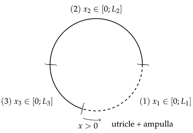
The anterior semicircular canal is modelled as a succession of 3 beams that are closed topologically. The first one corresponds to the utricle and ampulla system. The second one corresponds to the anterior SCC and the third one models the common crus between the anterior and posterior SCCs.
We also have the following relation between the natural pulses of different parts of the canal :
which will be the case for our model.
The contribution of the posterior SCC is modelled by a normal force discontinuity at beam 3 (common crus) :
In the same way as in the previous section, we will apply the boundary conditions for the model of the healthy inner ear, and analyse the analytical solutions – indeed, in this more complicated model, the majority of solutions are purely numerical.
3.2. Pathological Configuration
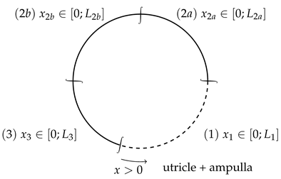
Pathology can be modelled by a discontinuity within the anterior SCC. A discontinuity in displacement and normal effort is applied :
The dehiscence is generally located between a third and two thirds of the anterior SCC, starting from the ampulla.
We will apply the following boundary conditions :
3.3. Anatomical Data
The data we are using comes from references [
1] to [
4]. These are approximate values for an anterior SCC. We take the density of water, as we are studying biological tissues. The radius of curvature is approximately
mm while the slender duct cross-sectional radius is approximately
mm. We will therefore assume that
.
In the physiological case, REF the pressure variation amplitude of the SCC are on the order of and contribute very little to the dynamics of the inner ear, and can thus be mostly discarded. The SCC also does not contribute to the ear’s sound perception, as sound is only perceived in the cochlea.
In the case of the dehiscence, the dynamics of the SCC become much more prevalent, with pressure variations in the order of REF. In this case, because of the third window, vibrations in the SCC have a much greater impact on the dynamics of the inner ear and notably the cochlea, meaning vibrations caused by sound outside sound will cause vibration in the SCC (which could lead to conditions like vertigo, loss of balance, ...).
In addition, with the opening of the third window, addition vibrations will come from the interior of the body, which will cause vibrations in the SCC, thus affecting the cochlea and creating a phenomenon of autophony. The dynamics of the SCC thus become fundamental in the dynamics of the whole inner ear, as the amplified vibrations could create tinnitus. On the other hand, vibration damping in the dynamics of the SCC could create a loss of hearing in certain frequency bands.
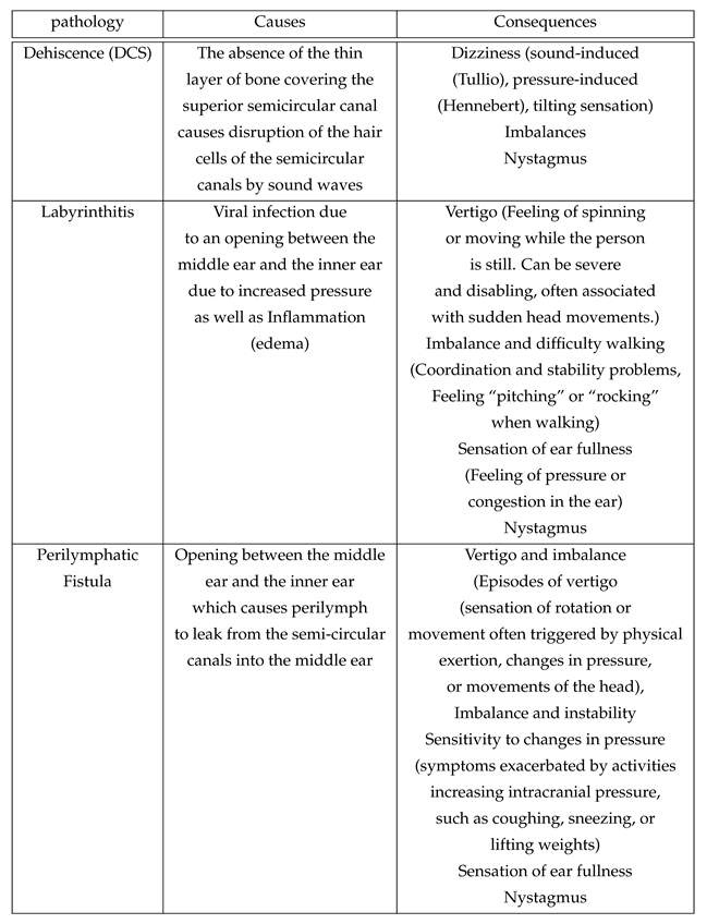
Related pathologies are described in the following table :
4. Application and Discussion
4.1. Model Implementation in Physiological Configuration
Applying the boundary conditions, we have the following system :
The nullity of the determinant in this system allows us to find simple solutions. Here are a few of them:
We can further find through relation
7,
which will provide another relation between the ratio of the lengths
and a ratio of integers with varying parities depending on the case being treated. This will limit the amount of cases which would actually be viable in practice given the set lengths
, and even more so were we to only consider low frequency cases – the higher frequency pulses being damped by the various low-pass filters created by the body’s tissues.
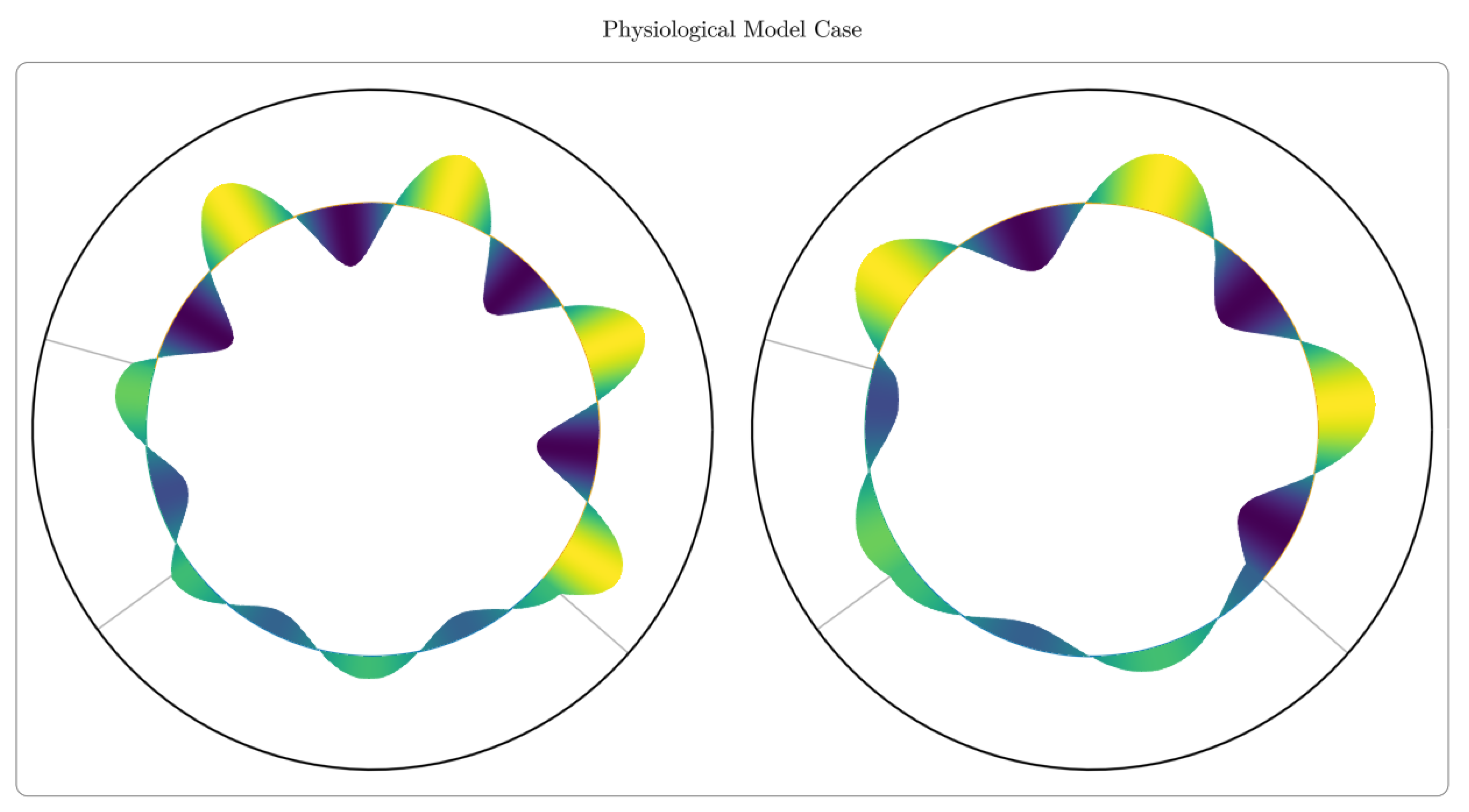
Shown above in
Figure 3 are screen captures of the cases (1) and (3) animated in Julia, for arbitrary
and
. We can notice discontinuities in the slopes of the normal displacement, which are a result of the varying cross sections of the different beams, regardless of the values of
and
.
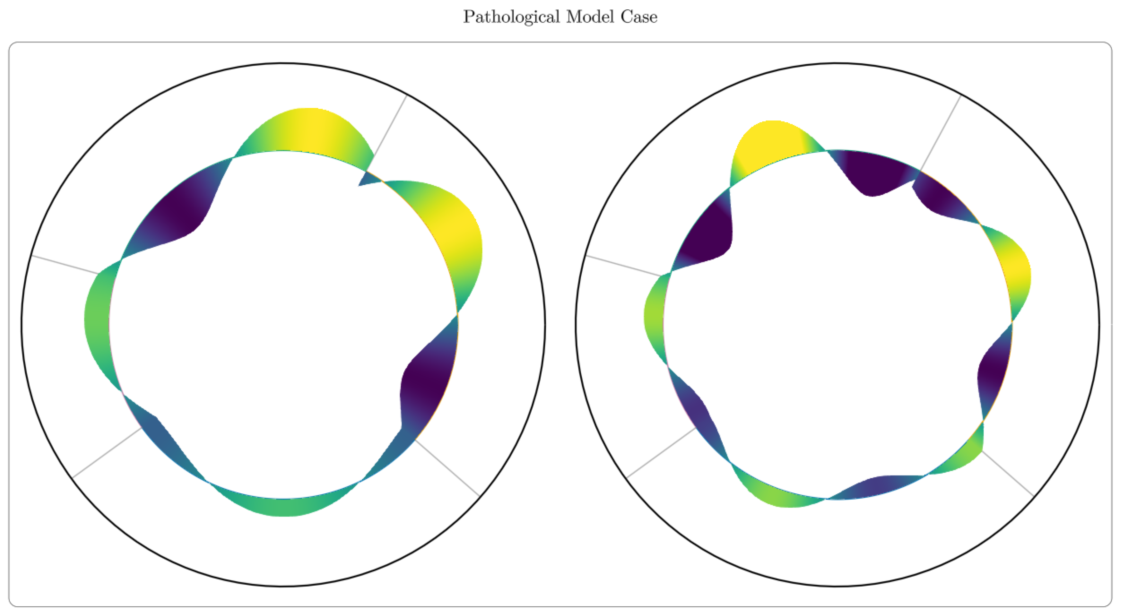
We ought to be careful using these visualisations as the displacement represented here radially is actually a longitudinal displacement. This representation was chosen for the sake of legibility.
4.2. Model Implementation in Pathological Configurations
As in the physiological case, there are simple modal solutions which are only possible under certain conditions (see table below).
Cases (1) and (2) are represented in the visualisation above. As expected, the analytical solutions provide a way to model the discontinuities both in displacement and pressure (through displacement derivative). We can now use these solutions to model different pathologies which correspond themselves to different discontinuities.
To fully understand the effect of these pathologies we can now exploit the frequency spectra of the model.
4.3. Frequency Response Function
The following results show the impact of the different conditions, described above, on the SCC’s dynamics modeled as a discontinuity on either or both pressure or displacement.
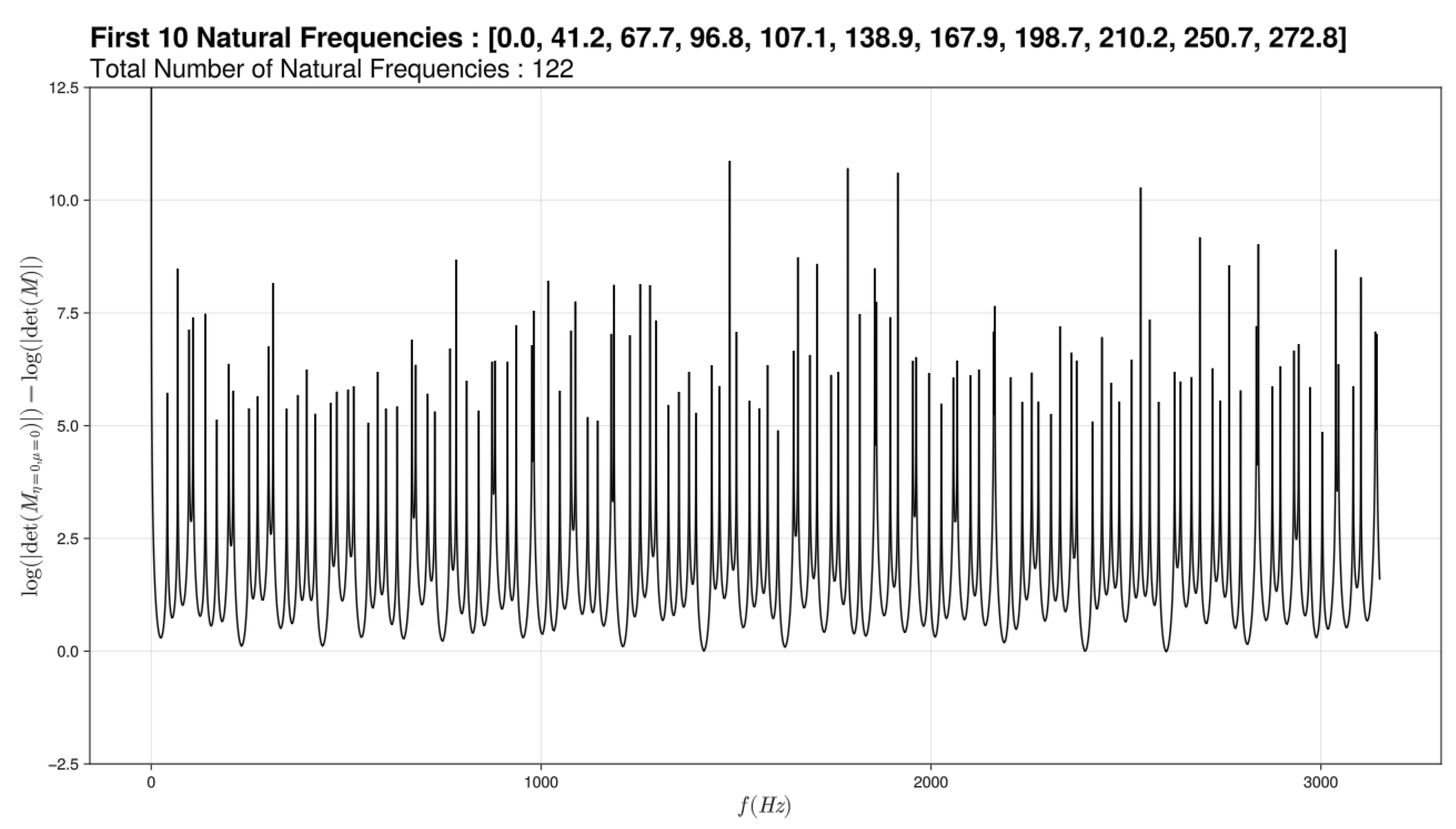
Figure 5.
Modeling graph of semi-circular canals for a healthy ear
Figure 5.
Modeling graph of semi-circular canals for a healthy ear
We traced frequency response function modeling the resonant frequencies of semicircular canals. We then obtain graphs of the log of the determinant of the system as a frequency response function in Hz, as a way to detect the zeros of the determinant corresponding to spikes towards infinity – the spikes not seeming to shoot to infinity being a simple artifact of the generously discrete nature of the frequency. We have chosen to include in its graphs 2 cursors: one on the discontinuity in viscosity and one on the spatial discontinuity. For a healthy ear, we thus get the graph above. A first deduction would be that semicircular canals react to audible frequencies.
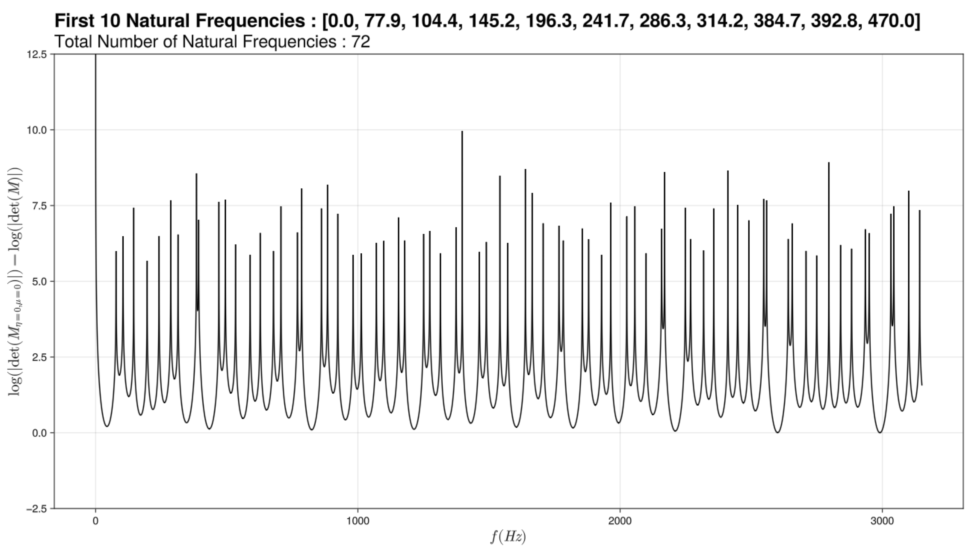
Figure 6.
Modeling graph of semi-circular canals for a sick ear
Figure 6.
Modeling graph of semi-circular canals for a sick ear
We notice that if we vary only slightly the (pressure discontinuity) nothing happens at the graph level but if this change is more important we have a loss of the lower frequencies. We have linked this graph to dehiscence. Indeed in the physiological case, the sound waves have no impact on the ciliated cells of the semicircular channels because their amplitudes are insufficient (some to mPa) which is modeled here by the small variation of the . Whereas in the pathological case, the sound waves are amplified (0.01Pa - 0.1Pa) by the hole present above the channels. The variation of the is therefore more important. The sound waves impact the hair cells of the channels.
The second graph is when we change both of the parameters.
Figure 7.
Modeling graph of semi-circular canals for a sick ear
Figure 7.
Modeling graph of semi-circular canals for a sick ear
For this first sub graph, we varied the (discontinuity on pressure) and the (discontinuity of displacement). This has been associated with labyrinthitis since we have assimilated edema to a more or less important obstruction and have coupled this obstruction to the increase in pressure that causes this pathology.
And if this phenomenon increases, this third graph is obtained.
In this case, no matter the external vibrations, nothing reacts.
The last graph represents the case where there is a loss of pressure within the system.
Figure 8.
Modeling graph of semi-circular canals for a sick ear
Figure 8.
Modeling graph of semi-circular canals for a sick ear
This graph was plotted for a negative which means there would be a loss of pressure. We have connected this with a perilymphatic fistula since it is due to a loss of fluid from the inner ear to the middle ear and therefore a loss of pressure in the inner ear.
5. Conclusions and Perspectives
5.1. Robustness and Predictivity
The 1D physiological model - elementary or segmented - accounts for longitudinal deformable modes in the canal - in fluid/solid environment interaction since the material is median. An essential result of this generic solution is the dimensional convergence of relative segment lengths to integer ratios, in the form of simple fractions that are actually observed anatomically. This is a convincing result of the natural optimization of these canals, which has been observed here particularly in the anterior canal.
The 1D pathological model, in which a passive singularity (Eulerian pressure discontinuity) or an active singularity (local Möbius inversion) generates different disturbances. In one case out of two, more than half of the constants given by the boundary conditions become indeterminate, i.e., we may have a free or random solution. Mathematically, this type of disturbance can induce modal noise in the channel’s behavior. We have here an opening towards vestibular tinnitus and also towards the possible subsequent controllability of these terms by additional boundary conditions.
Finally, the proposed approach allows discrete modeling of local or global disturbances, relatively robust in terms of global dynamics. This concerns both the pathology represented by a singularity (passive or active) and the damping entropy, developed per segment. On these two points, the proposed model represents a robust approach to both representation and prediction.
5.2. Future Applications and Extensions
Vestibular modeling on acoustic frequencies opens up a path towards weak coupling between auditory and balance acquisitions. While vestibular numerical models are well known, as are cochlear models, coupling matrices between the two are little explored. Models of this type may offer a way forward.
This is a relatively unexplored area, and the proposed model is a breakthrough in the field. In particular, we observe that material elements - fluids and solids - have similar characteristics in the cochlea and vestibule, and that vestibular pathologies can interact - positively or negatively - with those of the cochlea, and vice versa. The model discussed here effectively takes into account the acoustic capabilities of the semicircular canal.
In addition, the 1D model can also, by extension, lead to a transverse structural model (1.5 D bending) potentially carrying four types of singularities. This opening towards fourth-order structural equations could enrich the approach and include hybrid pathologies in particular.
In concrete terms, the modeled bar is based on the equation , of order two, whose generic solution - in terms of shape function – is harmonic, namely . Transverse bending displacement is represented by the equation , of fourth order, whose generic solution is both circular and hyperbolic: . This type of solution enables representations possibly extended to other structural modes and other types of singularities.
Author Contributions
Conceptualization, Y.G.; methodology, Y.G.; validation, Y.G. and Q.L; formal analysis, A.R., T.H. and M.-S. G.; investigation, A.R., T.H. and M.-S. G.; resources, Q.L.; data curation, A.R.; writing—original draft preparation, A.R., T.H. and M.-S. G.; writing—review and editing, Y.G.; visualization, A.R.; supervision, Y.G.; project administration, Y.G.. All authors have read and agreed to the published version of the manuscript.
Institutional Review Board Statement
In this section, you should add the Institutional Review Board Statement and approval number, if relevant to your study. You might choose to exclude this statement if the study did not require ethical approval. Please note that the Editorial Office might ask you for further information. Please add “The study was conducted in accordance with the Declaration of Helsinki, and approved by the Institutional Review Board (or Ethics Committee) of NAME OF INSTITUTE (protocol code XXX and date of approval).” for studies involving humans. OR “The animal study protocol was approved by the Institutional Review Board (or Ethics Committee) of NAME OF INSTITUTE (protocol code XXX and date of approval).” for studies involving animals. OR “Ethical review and approval were waived for this study due to REASON (please provide a detailed justification).” OR “Not applicable” for studies not involving humans or animals.
Informed Consent Statement
Not applicable
Data Availability Statement
We agree the ADPI statment.
Acknowledgments
In this section you can acknowledge any support given which is not covered by the author contribution or funding sections. This may include administrative and technical support, or donations in kind (e.g., materials used for experiments).
Conflicts of Interest
The authors declare that they have no known competing financial interests or personal relationships that could have appeared to influence the work reported in this paper.
Abbreviations
We thank Manon BLAISE for her briliant PhD about numerical modeling of semi-circular canals.
6.
To model the viscosity in beam 1, it is divided into N segments of length :
Assuming that the displacement of each segment can be written as :
This gives the possibility to model a change of
as a function of
x throughout the beam (1). To model a continuous
function thus comes of
and
following :
Our example models used the function :
We then have the following theorem to relate the different segments :
Theorem 1.
Proof of Theorem 1
can be rewritten as :
All the segments satisfy the continuous boundary conditions :
The sum of the square of the two equations gives (as
) :
which further implies that :
From (*) and (**), we finally obtain the result.
□
The most important consequence of this theorem is that the behaviour of each segment can be defined easily from the boundary conditions of beam (1). Without this method, the implementation of a viscosity function of x would render the PDE unsolvable with a function .
References
- Johnson Chacko, L. et al., Analysis of Vestibular Labyrinthine Geometry and Variation in the Human Temporal Bone. Front. Neurosci. 2018; 12, 107. [Google Scholar] [CrossRef]
- Lee, J.-Y. et al, A Morphometric Study of the Semicircular Canals Using Micro-CT Images in Three-Dimensional Reconstruction Anat. Rec. 296:834–839. 2013. [Google Scholar]
- Iversen, M. , Rabbitt R., Wave Mechanics of the Vestibular Semicircular Canals, Biophys. J.,vol. 113, Issue 5, pp.1133-1149. 2017; ISSN 0006-3495. [Google Scholar] [CrossRef]
- David R. et al., Supplementary Information for: Assessing morphology and function of the semicircular duct
system: introducing new in-situ visualization and software toolbox. Sci. Rep. 2016, Supplementary information
for the article "Assessing morphology and function of the semicircular duct system: introducing new in-situ visualization
and software toolbox." by David et al. which are available online: https://www.nature.com/articles/srep32772.
- Piton, J. , Négrevergne M., Portmann D., Dehiscence of the superior semicircular canal: Approach and CT scan classifications. Rev. Laryngol. Otol. Rhinol. 2008.
- Philippe Herman, Fistules périlymphatiques. Available online: https://traitesdemedecine.fr/table-des-matieres/s26-oto-rhino-laryngologie/s26-p01-c08-fistules-perilymphatiques/ (accessed on 10 July 2024).
- Mickie Hamiter, Purulent labyrinthitis. Available online: https://www.msdmanuals.com/fr/accueil/troubles-du-nez,-de-la-gorge-et-de-l%E2%80%99oreille/troubles-de-l%E2%80%99oreille-interne/labyrinthite-purulente (accessed on 10 July 2024).
- Werner Graf, François Klam, The vestibular system: comparative and functional anatomy, evolution and development. Available online: https://www.sciencedirect.com/science/article/pii/S1631068305001867 (accessed on 17 July 2024).
- Docteur Catherine Vidal, Dizziness and disorders of balance. Available online: https://www.docteurvidal-iec.com/otoneurologie/vertiges.html (accessed on 18 July 2024).
- S. KHARRAT et al., DEHISCENCE OF THE SUPERIOR SEMI-CIRCULAR CANAL LA RABTA hospital. TUNIS. 2010, which is available online : https://www.ajol.info/index.php/jtdorl/article/download/64252/52047.
- Arnaud ATTYEMichael ELIEZER, Towards a generalization of late acquisition for the exploration of cochlear-vestibular disorders in MRI? Available online: https://ebulletin.radiologie.fr/e-quotidien-jfr-samedi/generalisation-lacquisition-tardive-lexploration-troubles-cochleo (accessed on 18 July 2024).
- M.DELIAT.,Post-traumatic perilymphatic fistulas: etiopathogenesis-diagnosis-treatment University of Limoges 1967, which is available online :https://aurore.unilim.fr/theses/nxfile/default/0a3e3eca-464f-4895-851d-75a8c9adab07/blobholder:0/M1998158.pdf.
- Iversen MM, Zhu H, Zhou W, Della Santina CC, Carey JP, Rabbitt RD., Sound abnormally stimulates the vestibular system in canal dehiscence syndrome by generating pathological fluid-mechanical waves. Sci Rep. 6 juill 2018;8(1):10257.
- Goycoolea MV, Muchow D, Schachern P., Experimental studies on round window structure: Function and permeability. The Laryngoscope. juin 1988;98(S44):1-20.
- Buck, A. , The Mechanism of Hearing. Edinb Med J. nov 1874;20(5):468.
- Minor LB, Solomon D, Zinreich JS, Zee DS., Sound- and/or Pressure-Induced Vertigo Due to Bone Dehiscence of the Superior Semicircular Canal. Arch Otolaryngol Neck Surg. 1 mars 1998;124(3):249.
- Yuen H, Boeddinghaus R, Eikelboom RH, Atlas MD., The Relationship Between the Air-Bone Gap and the Size of Superior Semicircular Canal Dehiscence. Otolaryngol Neck Surg. déc 2009;141(6):689-94.
- Chien W, Ravicz ME, Rosowski JJ, Merchant SN., Measurements of Human Middle- and Inner-Ear Mechanics With Dehiscence of the Superior Semicircular Canal. Otol Neurotol. févr 2007;28(2):250-7.
|
Disclaimer/Publisher’s Note: The statements, opinions and data contained in all publications are solely those of the individual author(s) and contributor(s) and not of MDPI and/or the editor(s). MDPI and/or the editor(s) disclaim responsibility for any injury to people or property resulting from any ideas, methods, instructions or products referred to in the content. |
© 2024 by the authors. Licensee MDPI, Basel, Switzerland. This article is an open access article distributed under the terms and conditions of the Creative Commons Attribution (CC BY) license (http://creativecommons.org/licenses/by/4.0/).
