1. Introduction
Intuitively, clean air is necessary for good health. Air pollution happens from both natural (for example, volcanoes and decaying organic mass in oceans) and man-made (for example, burning wood for heating, fuel-based engines, and industrial byproducts) sources. Throughout decades, medical researchers have been studying the impact of polluted air on human health. Air pollution has been linked to up to 9 million premature deaths globally [
1]. In 2015, the World Health Organization adopted a landmark resolution on air quality and health. In that resolution, air pollution was identified as a risk factor for noncommunicable diseases such as stroke, asthma, lung cancer, etc., putting it on the same level with other major health risk factors such as unhealthy diets and tobacco smoking [
2]. In 2021, WHO published their latest guidelines [
3]. Based on the WHO resolutions and guidelines, the European Union has adopted its own air quality standards in the form of the Ambient Air Quality Directives (AAQD) 2008/50/EC to set air quality standards for 12 air pollutants: sulfur dioxide, nitrogen dioxide / nitrogen oxides, particulate matter (PM
10, PM
2.5), ozone, benzene, lead, carbon monoxide, arsenic, cadmium, nickel, and benzo(a)pyrene [
4]. In 2020, the EU updated the 2008/50/EC to resemble the new WHO guidelines more closely [
5].
When it comes to measuring air quality, the AAQD documentation recognizes fixed measurements and indicative measurements, followed by possible data modeling or postprocessing with or without the use of machine learning methods [
6]. Fixed measurements are taken by the fixed measurements stations, rather expensive, complex, and precise pieces of equipment placed in big, permanent installations. These fixed stations are also known under the names of conventional, regulatory, or reference measuring stations. Although they provide reliable and accurate data, due to their size and price, it is not possible to have them placed in every critical zone, as required by [
6]. Also, these stations provide hourly measures, making them unusable in early detection scenarios. In contrast, indicative measurements are taken by indicative measurements stations, relatively cheap and less accurate devices in comparison to fixed stations. The basis for indicative stations is low-cost particulate matter sensors, often abbreviated as LCPMS, so these stations are often called LCPMS measuring stations. The goal of AAQD is that fixed measurements should be supplemented by indicative measurements (and possible modeling and/or objective estimation) to enable point data to be interpreted in terms of geographical distribution of concentrations and the reduction of the required number of fixed stations, resulting in a better data, lower cost, and real-time monitoring [
6].
It is well established that indicative stations suffer from certain drawbacks, mostly in terms of component quality, measurement reliability, and their relative lifetime [
7]. There are many efforts to overcome these problems without raising the price of the indicative device, branching in different directions, and trying to solve different issues [
7,
8]. This paper is focused on overcoming one such shortcoming of indicative stations.
When it comes to measuring particulate matter concentrations, specifically PM
2.5 and PM
10, there exist multiple measuring techniques. Out of all available techniques, all the LPCMS employ a light scattering method due to its low cost [
9]. The basic idea is simple: when a particle passes through a light beam, part of the light deviates from the original path, producing a scattering [
9]. The characteristic intensity of scattered light is precisely predicted by the Mie theory and by analyzing it, the particle size distribution can be determined [
9]. It was reported that indicative stations employing light scattering based particulate matter sensor can exhibit good performance with high accuracy, if they have been calibrated in the laboratory by the manufacturer and in-field by the implementor [
9].
Even with calibrations, it was reported that all LCPMS report serious degradation in accuracy in high relative humidity conditions, causing the device to significantly overestimate particle counts [
9,
24,
27,
29]. Simply put, high relative humidity causes certain aerosol particles present in the air to consume water vapors from the air. This happens because of the hygroscopicity property of some particles, that is, their ability to absorb water (for example, it comes as no surprise that NaCl particles in the aerosol will absorb water) [
24]. This process causes smaller particles to grow because of the absorbed water, therefore scattering the light differently and causing sensor to incorrectly put them in the larger bin than they really should be in. [
32] explains this hygroscopic growth represented as the particle size hygroscopic growth factor:
Equation 1 shows that the hygroscopic growth factor (GF) at the given relative humidity (RH) is defined as a ratio of the diameter of the particle (D) at that same relative humidity to that of dry particle (Dd).
As a result of this hygroscopic growth, the light scattering sensors overestimate the PM
2.5 and PM
10 concentrations, causing possible health hazard alerts, although most of those hygroscopic particles are mostly condensed water and don’t have any adverse effects on the health [
9]. To remove these hygroscopic effects, fixed stations are equipped with huge presampling chambers (dryers) that bring the air to a specific temperature and relative humidity values before letting them reach sensors [
24]. LCPMS cannot afford this approach due to both size and price constraints (dryers are big and cost a lot), so they most often deal with this issue in a different way. Some LCPMS:
Employ different algorithms to compensate elevated measured levels (including averaging of values or machine learning models [
10]).
Detect such environmental conditions and report that no reliable measurements are available for that period [
11].
Use calibration methods based on the relative humidity values and K value parameter for hygroscopicity of air mixture [
25].
This paper takes the approach of using low-cost dryers to remove the water from the air and reduce the negative effects of the relative humidity on the reported results. The aim is to improve the accuracy of low-cost indicative stations in measuring particulate matter, while keeping the equipment cost low and in the acceptable range for the low-cost indicative devices. It does so by presenting a novel design of the inlet that uses strategically placed heaters to preheat the air before it reaches the sensor. More specifically, this paper puts forward two hypotheses:
H1: it is possible to predict when will the hygroscopic particles be formed based on the relative humidity and temperature values.
H2: a proposed novel inlet use will reduce the effect of the hygroscopic particles on the measured PM2.5 and PM10 levels, giving more accurate measured values.
Chapter 2 presents related work in effect of hygroscopic particles on measured levels of PM2.5 and PM10. Chapter 3 describes the indicative station containing the novel inlet and particulate matter sensor. It also describes the testbed for the system and testing scenarios. Chapter 4 presents the findings and draws conclusions on the approach taken. Finally, a conclusion is given.
2. Related Work
Conventional, fixed, regulatory, or reference measuring stations provide accurate measurements of air pollutants, but they are physically big, require heavy investments and qualified personnel to run, making it hard to deploy them at a large scale. To better assess local pollution levels and get almost instantaneous readings, an addition to conventional stations is proposed; the low-cost sensor-based, or indicative measuring stations are envisioned to complement fixed stations. They are cheap, small-sized, easy-installed, offer real time coverage, and can easily be deployed at a dense scale, although they don’t necessarily provide the same measurement reliability or lifetime. The hearts of these indicative stations are solid-state chemical sensors for gaseous air pollution monitoring, and scattering-based particulate matter sensors for detecting mainly PM
2.5 and PM
10 [
9], with this paper focusing on the latter. There are many efforts in the scientific community and industry to improve these indicative measuring stations to more reliable and accurate measure particulate matter levels in longer periods. One direction of research is designing, building, and investigating low-cost particulate matter sensors (LCPMS). As stated in [
9], the amount of different peer reviewed LCPMS models went from 7 in 2017 up to 50 in 2020, showing a huge increase in available options. In [
26], authors give a review of literature on the usage of low-cost sensors to measure particulate matter.
All LCPMS are pre-calibrated by the manufacturer by using laboratory-level calibration aerosols [
13]. In these calibrations, the environment is carefully controlled, most notably the temperature, relative humidity, and aerosols shapes and concentrations. According to [
9,
19], three tested sensors (Samyoung DSM501A, Shinyei PPD42NS, and Sharp GP2Y1010AU0F) exhibited high linearity against reference instrument, with
R2 up to 0.9755, but the test also showed that sensor readings were affected by the humidity and particle size and composition. In [
30], researchers have shown that the tested LCPMS (Sharp GP and Sharp DN) showed a correlation
R2 of above 0.97. In a testing chamber capable of simulating environments with temperatures from 5° to 40° and relative humidity from 10% to 90% and stable pollutant concentrations, authors show that a LCPM sensor (HPMA115S0 Honeywell) exhibited
R2 values above 0.96 [
9,
21].
However, although in laboratory environments LCPMS display high correlation with reference instruments, it was shown that aerosols used in the testing chambers differ significantly from aerosols found in outdoor environments [
12,
13]. The [
9,
12] show that laboratory-calibrated only devices commonly can exhibit
R2 values lower than 0.5 in real outdoor environments, so field-calibration is required. Additionally, to improve LCPMS performance, postprocessing calibration strategies are implemented and they usually include models with corrections for hygroscopicity, linear regression models, and other machine learning algorithms [
9,
14,
15,
16,
17,
18].
Many authors have reported interference caused by relative humidity. In [
19], authors report that the water in the air affected the accuracy of the sensors in three ways, most notably by absorbing light and causing an overestimate of particle mass concentrations due to the reduced light intensity received by the phototransistor. They also reported that the temperature did not play any significant role. Some authors show that high relative humidity can cause serious disruption to sensors’ measurements [
11,
22,
23].
Most studied approach in literature to mitigate the influence of relative humidity is by applying different correction algorithms. Authors in [
28] propose a correction factor dependent on relative humidity to be applied to measured data to remove the effects of high relative humidity. The paper [
27] introduces a correction algorithm where relative humidity effects can be better described by taking into the account the detailed particle size profile, allowing the algorithm to account for the high relative humidity artefacts on the measured concentration levels. In [
30], authors apply different machine learning methods to improve the calibration algorithms to increase the accuracy and mitigate the impact of relative humidity on the readings.
3. Materials and Methods
3.1. Design of the Novel Indicative Air-Quality Measuring Station
In this paper we present a novel indicative air-quality measuring station design. The station contains sensors to measure both gases (like benzene, lead, carbon monoxide, etc.) and particulate matter. For this paper, only the part of the station relevant to measuring particulate matter, specifically PM2.5 and PM10, will be discussed.
The heart of the station is the low-cost particulate matter sensor Alphasense OPC-N3 Optical Particle Counter, based on light scattering technique. The performance of this sensor has been extensively studied [
10,
31] and, like with other LCPMS, it has been shown that it suffers from the effects of high relative humidity. Therefore, a novel design that includes air heating was developed for the measuring station.
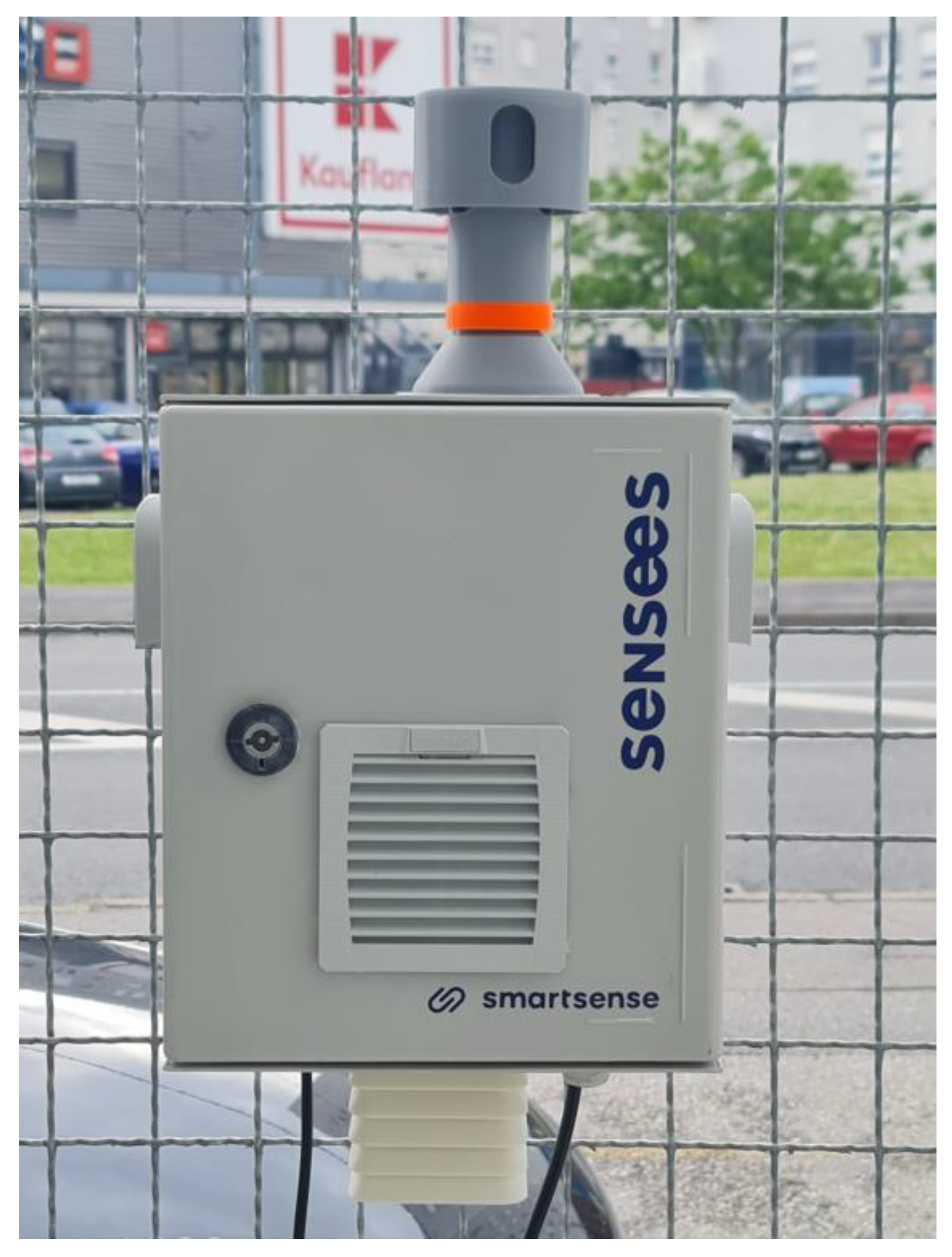
Figure 1 shows the full station, designed and manufactured to reduce the effects of the relative humidity on particulate matter measurements.
For this paper, the top-most part of the station is interesting because it houses the inlet of the particle measurement subsystem.
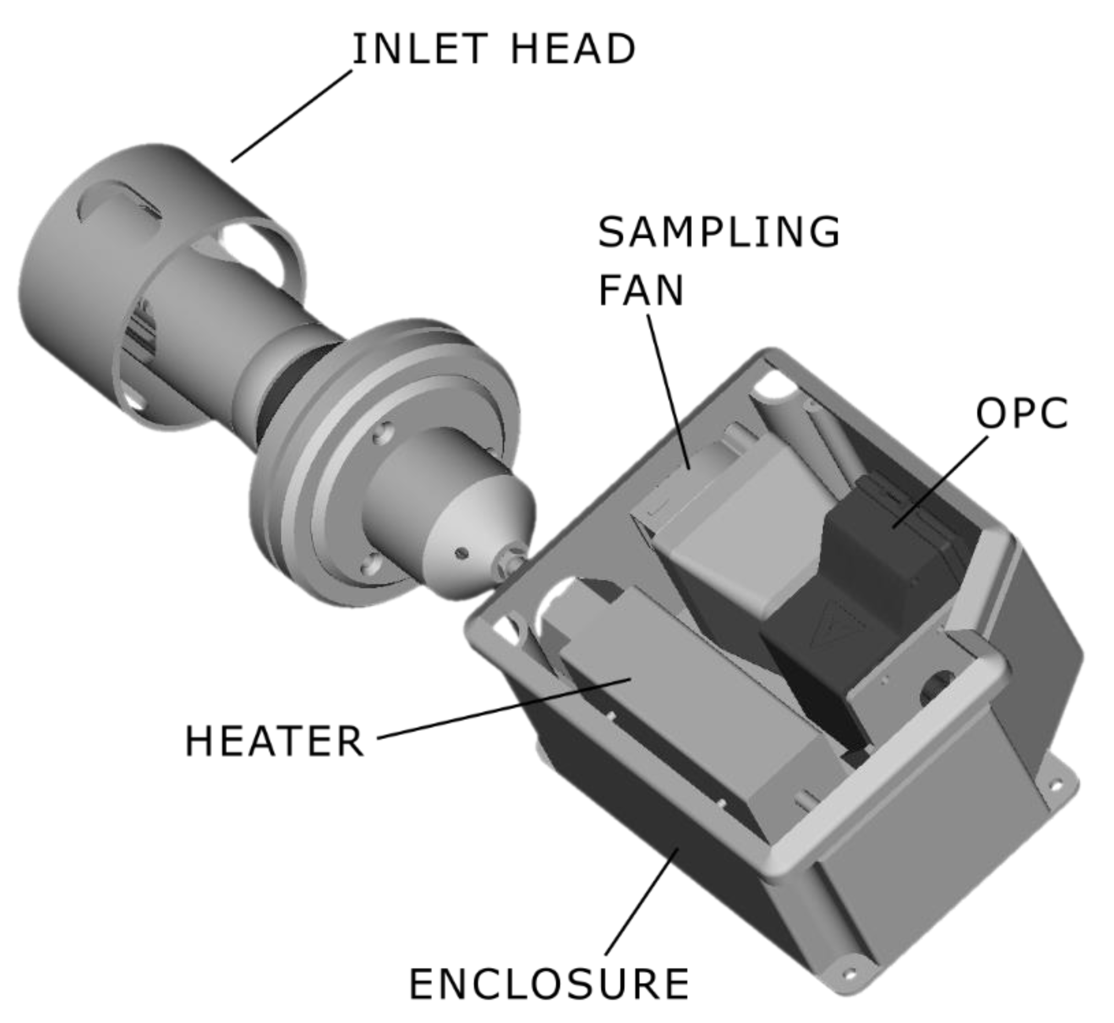
Figure 2 shows main parts of that subsystem.
The air enters the inlet head, then goes through the conditioning tunnel, and enters the measuring chamber, where the Alphasense OPC-N3 sensor is located. This design forces the air to pass through a conditioning tunnel with the goal of bringing microclimate parameters of the air, such as temperature and relative humidity, to a preferred range considering the used sensor technology.
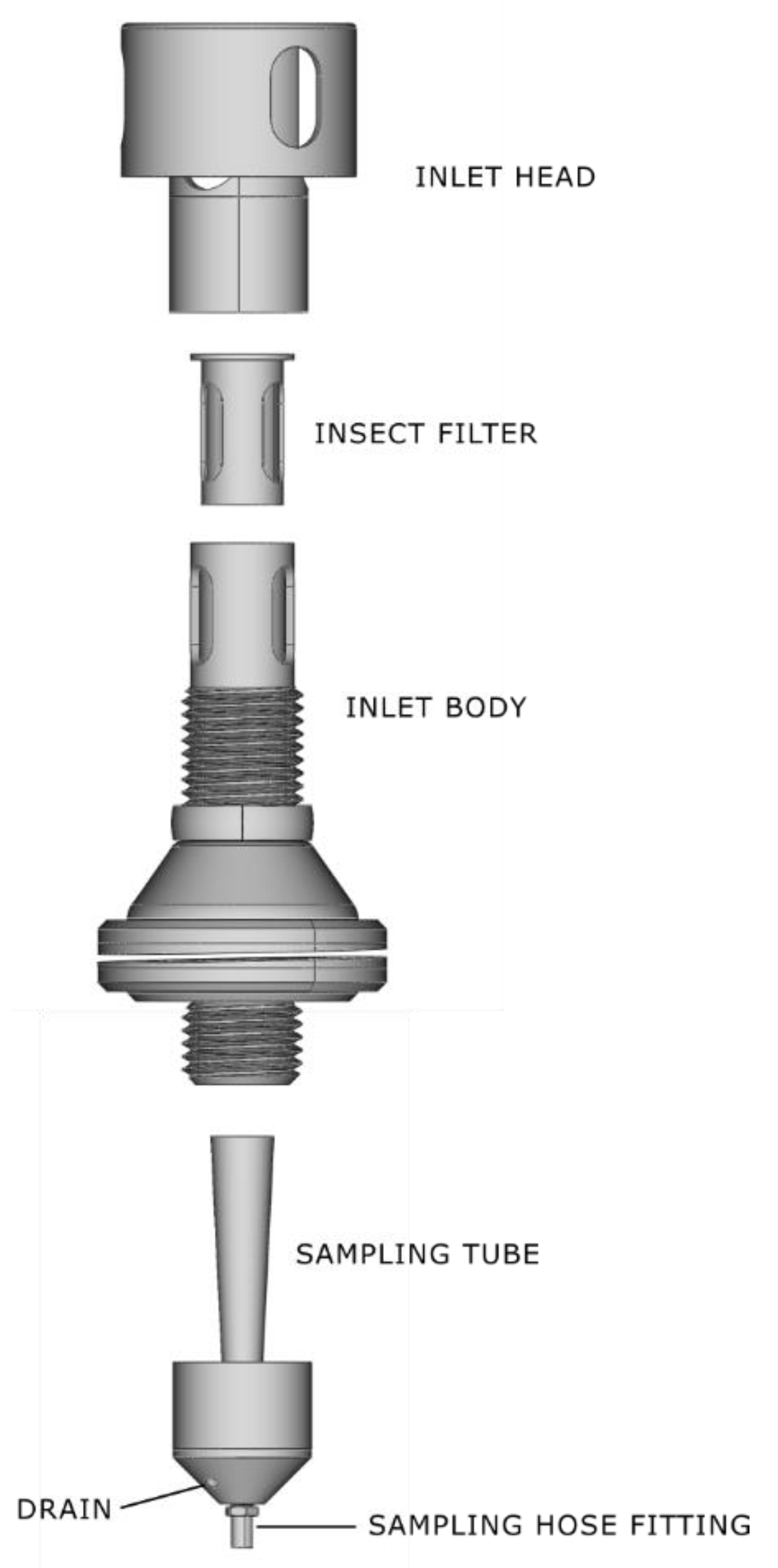
Figure 3 shows a more detailed view of the particle matter measuring subsystem.
The air enters the subsystem through a sampling head which is designed to enable easy entry of PM
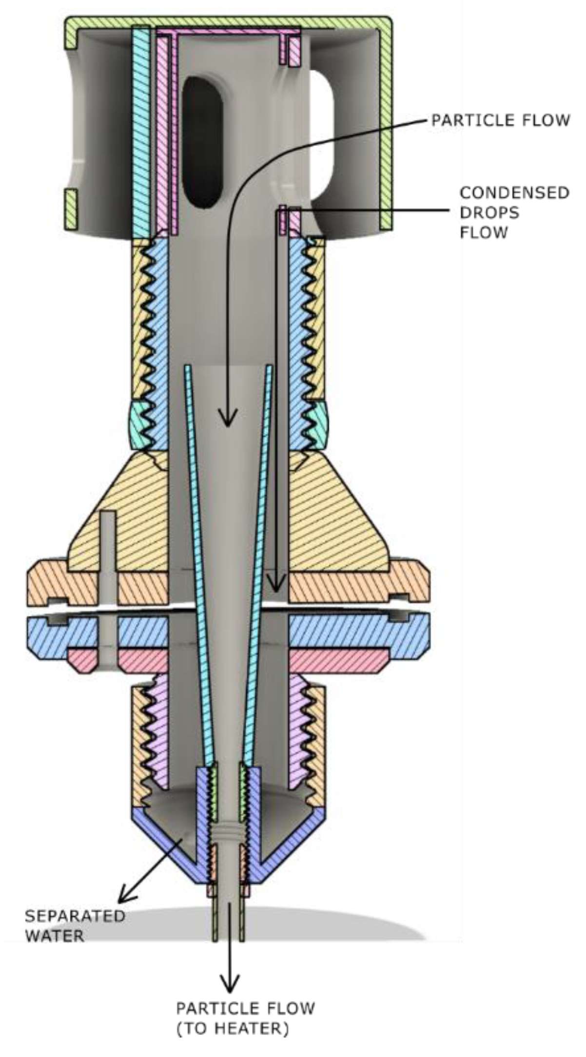
10 and lower sized particles, while preventing coarser grained dust and sand from entering the sampler. At the same time, it provides protection from the rain and sun. Inside the head there is a filtering net to prevent the entering of insects, as well as other macro particles like pollen. Special care is taken while designing the inner sampling tube. It maximizes the air flow from the sampling head, while allowing condensed water to drain over the sides of the main inlet body down to the drain hole. From the drain hole, water is drained out using the drain tube trough the monitoring station all the way to the dedicated opening at the bottom. This is very important; to prevent condensed water droplets to enter optical particle counter sampling path, because heating system cannot remove big, condensed drops of water from the intake path.
Figure 4 shows this in a graphical way.
From the sampling head, the air goes to the conditioning tunnel. The main component of the conditioning tunnel is a spiral 30 W heater. As the air passes through, the heater raises its temperature. When the air reaches the particle counter, it is heated, and most hygroscopic particles have been significantly reduced in size. That causes similar effects like in big preconditioning dryers in referent stations and allows the particle counter to measure more accurate value, while keeping the size, price, and complexity of the station low.
Sample flow control turned out to be an important aspect of the heated sampling system, so both the heater and the air flow through the system had to be regulated. The main problem was that adding any additional tubing, heaters and ducts to the OPC N3 causes its sample flow to drop from nominal 4 - 6
to 0.7 - 0.8
. Because the flow is used in OPC internal algorithms to calculate mass of particles per volume, the low flow results with greater scattering of the measurements, depending on the particle concentration. The problem was solved by adding an external sampling fan as shown in
Figure 2. This fan can generate significantly higher air flow than the one in OPC N3, thus allowing the system to control the sample flow at intended 4 - 6
by using PID controller. In general, the flow is affected by wind, air pressure, temperature and other factors, so by being able to stabilize the flow, and control the heater temperature, the system was able to achieve significant improvements in measurement precision and availability. The heater control was set to keep the temperature at 45
OC, and the sample flow rate at 5
.
3.2. Rationale for Heating the Air
The rationale for the raising of the temperature is explained next. [
33] states that the relative humidity (
RH) shows how much water is in the air compared to the maximum water vapor the air can hold at a specific temperature, expressed as a percentage. A dew point is defined as the temperature of the air required to achieve
RH = 100%. Below this temperature, the air cannot hold any more water so the water will start to condense. The equation 2 [
33] shows the relation between dew point, air temperature, and relative humidity:
In equation 2,
Dp is the dew point temperature,
T is the air temperature, and β = 17.625 and λ = 243.04°C are revised Magnus coefficients recommended in [
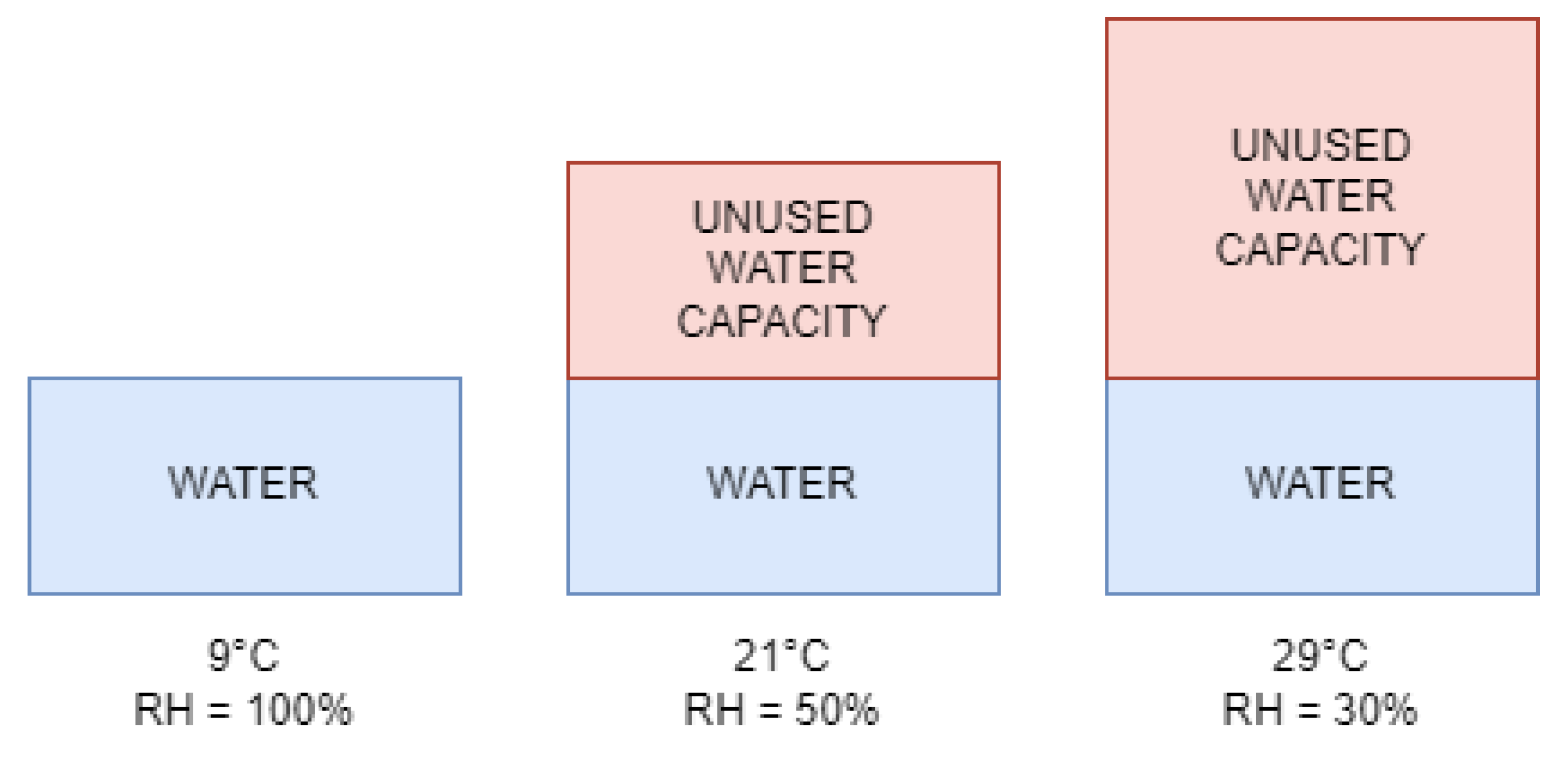
33]. The said equation suggests that the increase in the temperature will decrease the relative humidity. That concept can be shown visually in
Figure 4.
Figure 5 plastically shows that, although the amount of water in the air remains the same, the increase in temperature allows more water to be present in the air and therefore lowers the relative humidity.
Progressing from that, authors in [
34] show that lowering the relative humidity will cause hygroscopic particles to decrease in size, which is exactly the purpose of the design.
3.3. Experiment Setup
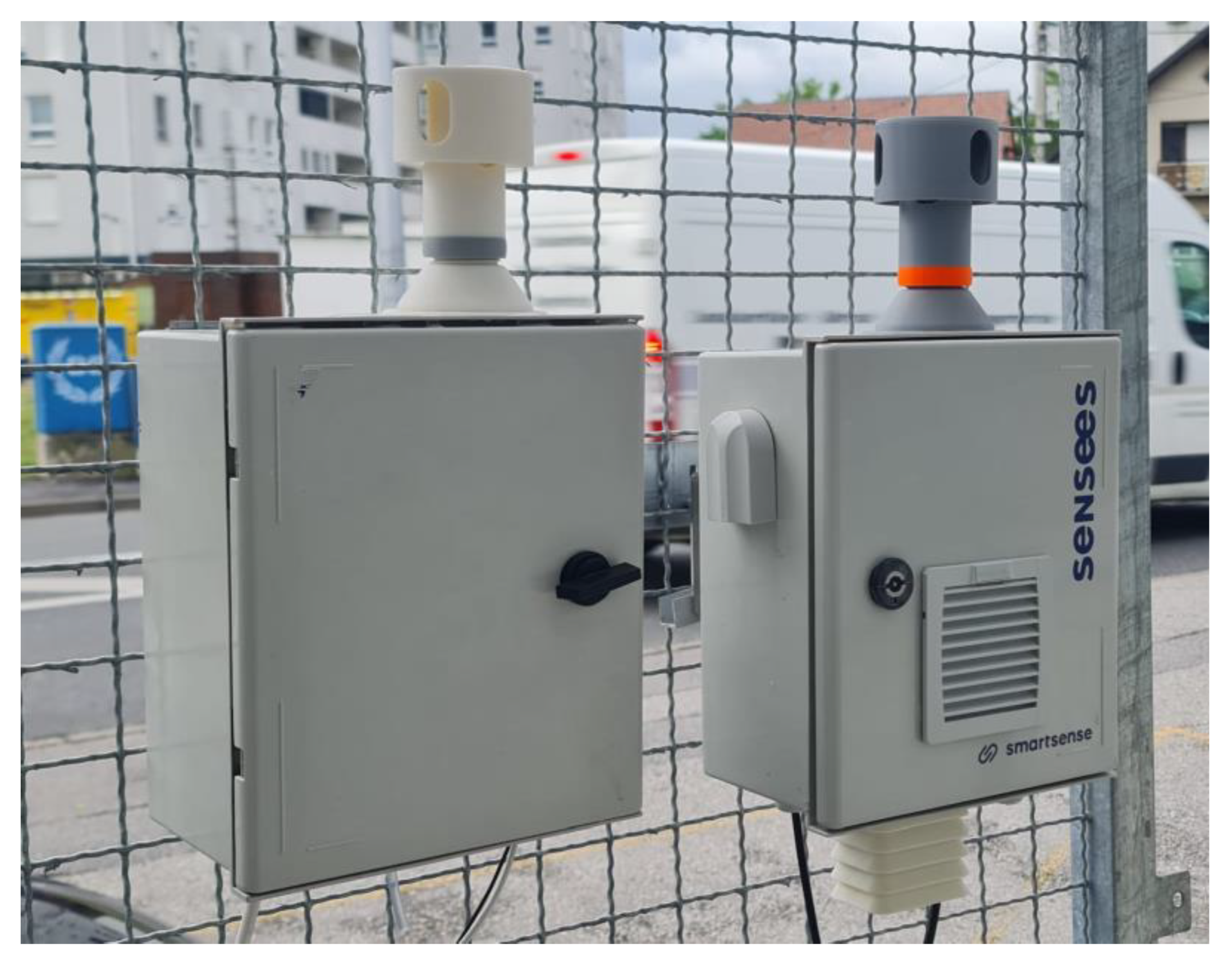
The experimental setup included two monitoring stations with exactly the same configuration, except that one of them was equipped with the subsystem for heating the air proposed in this paper, and the other one was not. Otherwise, they shared the same mechanical and electronic components and run the same software.
Figure 6 show the placements of both stations, the one equipped with the subsystem for heating the air proposed in this paper being on the right.
The monitoring stations were equipped with five electrochemical gas sensors (NO, NO2, CO, O3 and SO2), and one OPC N3 particle counter measuring PM10, PM2.5 and PM1 types of particles. Additionally, each monitoring station included external meteorological sensors (temperature, relative humidity and atmospheric pressure) enclosed in radiation shield. To keep both stations as similar as possible, one monitoring station was equipped with the new heated sampling inlet, and the other was equipped with the same inlet, just without the heating.
Both stations were collocated on the same installation location, making sure that their PM sampling inlets are as close as possible and on the same distance from the ground. In this experiment, data from the referent monitoring station was not used, although GRIMM EDM 264 automatic sampler instrument for monitoring and supervision of the experiment was used. The reason for this was to show the difference in performance of the otherwise same optical particle counters with regards to conditioning of the sampler. In other words, this experiment was not interested in the absolute accuracy of the data, but rather the relative comparison between the two.
The installation location and the season were selected to provide both regular periods with the high relative humidity combined with those with normal conditions. One important goal of the experiment was not only to prove the benefits of the heating of the input samples when the conditions require it, but also to make sure there are no side effects of this setup in normal conditions when the heating is not required. The results were an important input for the design of the heating regulation control firmware. The main question was whether to have strict humidity and temperature thresholds, including hysteresis, for switching on and off the heater, or is perhaps the better strategy to have the heater on all the time, with the set temperature target, thus avoiding negative effects of sudden changes of temperature and humidity on the measurements.
The testing was performed in the winter and spring seasons, allowing the monitoring stations to be exposed to many different conditions ranging from the cold weather in winter to the periods of huge daily temperature and humidity swings during the spring season. Also, urban location was chosen, next to a busy street which provided good daily dynamics of the particle concentrations, so that the devices were exposed regularly both to the low (clean air) and elevated levels of the PM concentration. At no point, during the test period, did the particle concentration at the test location reach high levels that could pose health issues. This was also confirmed by the GRIMM EDM 264 instrument.
Both monitoring stations also contain the power supply subsystem and the gateway. The gateway provides 4G connectivity and has a task of configuring and reading the OPC N3 counter. The particles are sampled every couple of seconds, and then one-minute averages are calculated. One-minute averages are then sent to the backend server where they are stored and can be visualized on the frontend application. The conducted experiments have shown that the minute intervals are sufficient, providing enough data granularity on one side, while filtering out volatile swings of PM concentration characteristic for suspended particles.
4. Results
The experiment was conducted over a period of 19 weeks, with two weather stations included - one conditioned and one unconditioned. The sensors measured the concentrations of PM1, PM2.5, and PM10 particles at a sampling rate of 1 minute, and the difference between the two sensors was calculated.
The heatmaps in
Figure 7 show the relationship between the difference in measurements between the unconditioned and conditioned sensors, and the relative humidity. The results indicate that larger particles (PM
10) are more sensitive to increased humidity in the outside air.
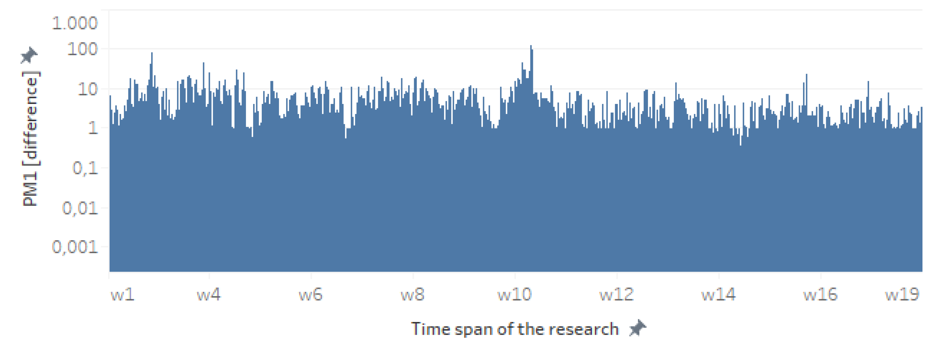
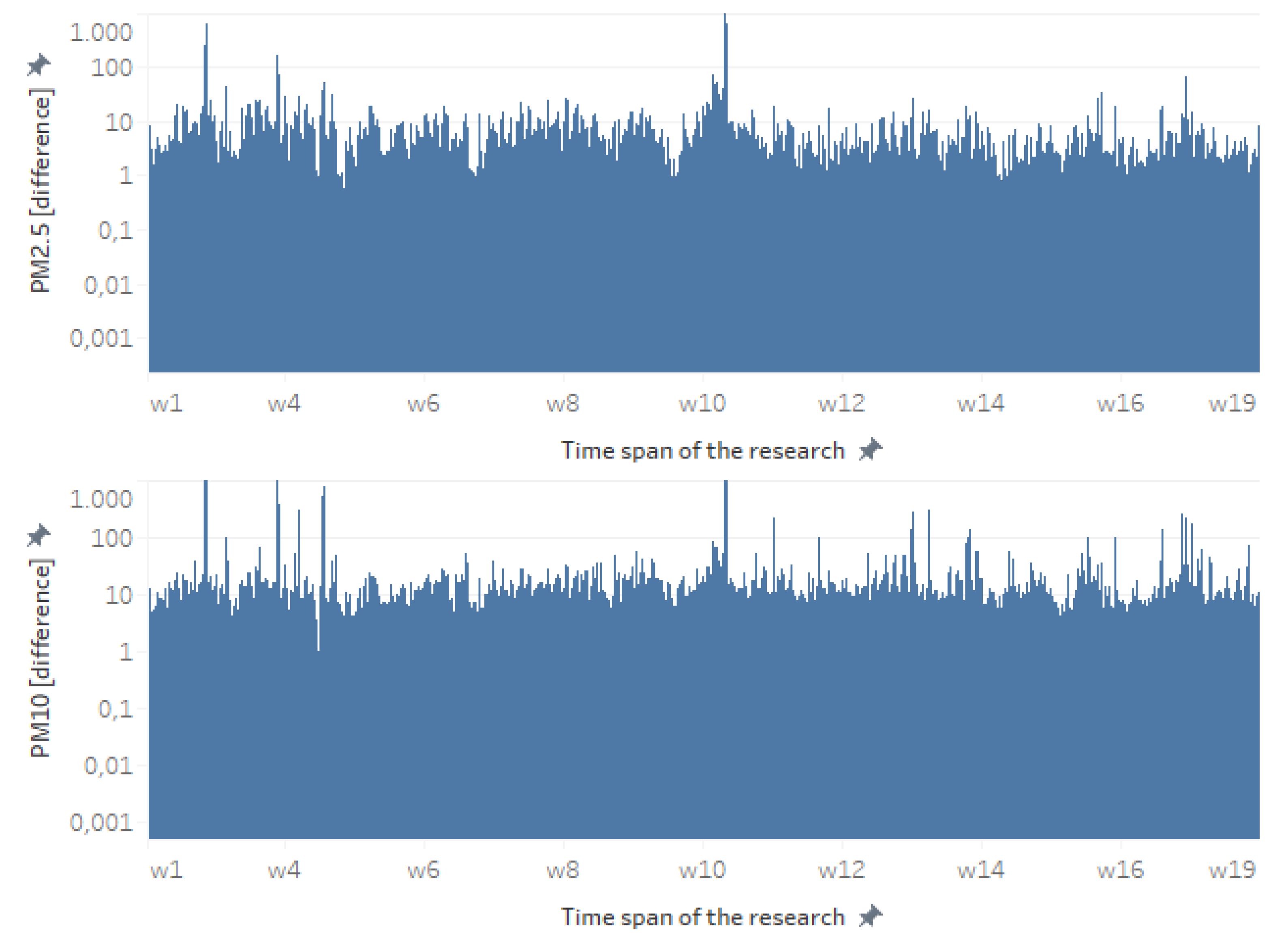
To further analyze the difference between the conditioned and unconditioned sensors, the absolute differences in the sampled values were visualized over the entire experimental period for each particle size (
Figure 8). The results confirm that the differences are larger for larger particles, with PM
1 differences ranging up to approximately 100 particles, PM
2.5 ranging up to 1000, and PM
10 often close to or over 1000.
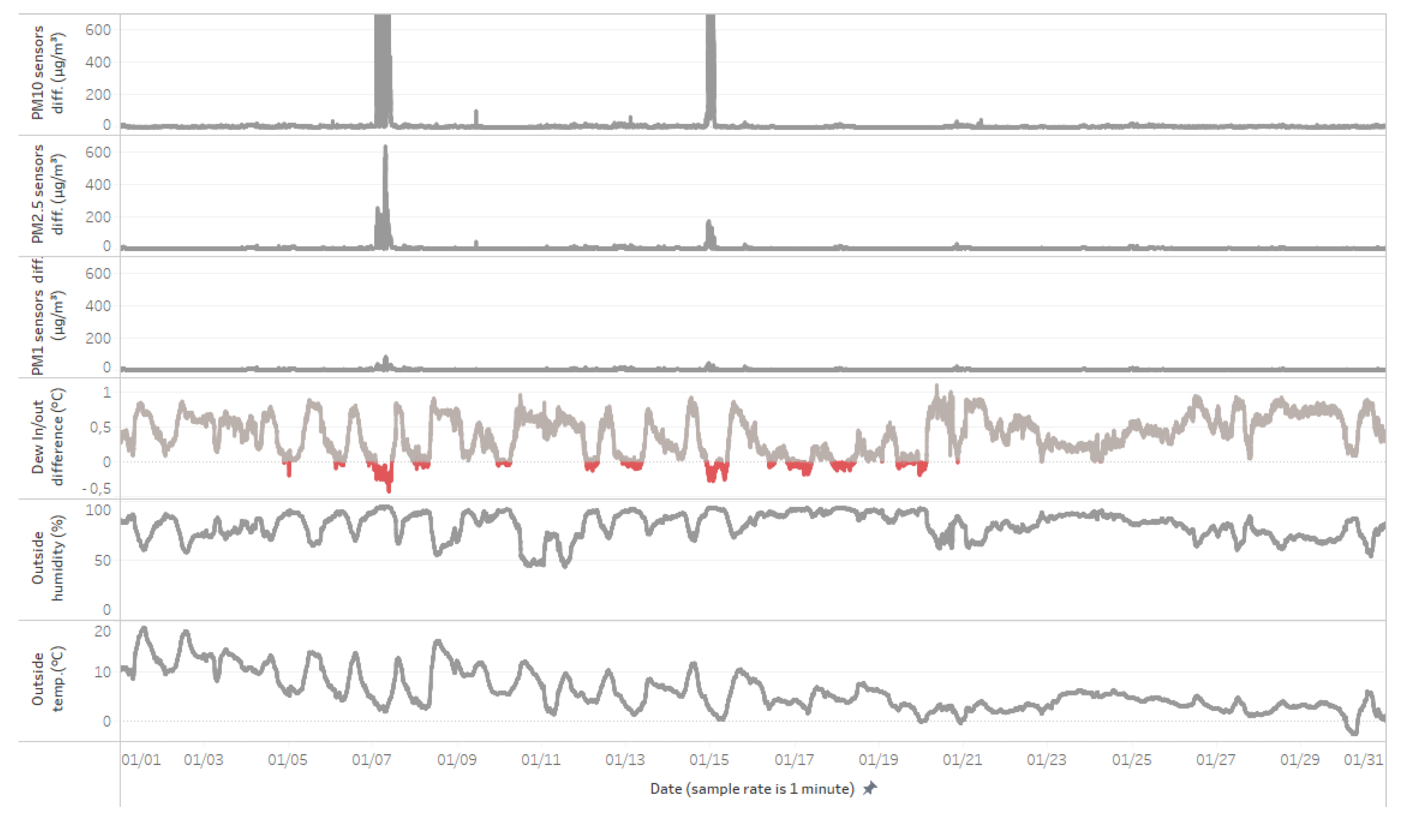
The prominent peaks observed in
Figure 8 were further analysed in the context of dew point, the difference between measurements of unconditioned and conditioned sensors, outside humidity, and outside temperature (
Figure 9). The results show that the highest measurement error is observed for the largest particles (PM
10), and this error is correlated with negative values of the dew point difference (i.e., when the outside dew point is lower than the inside dew point).
The relationship between the dew point difference and the difference between unconditioned and conditioned sensor measurements is further illustrated in
Figure 10. The results show a clear correlation between the dew point difference and the sensor differences, with larger particles (PM
10) being more affected by changes in dew point.
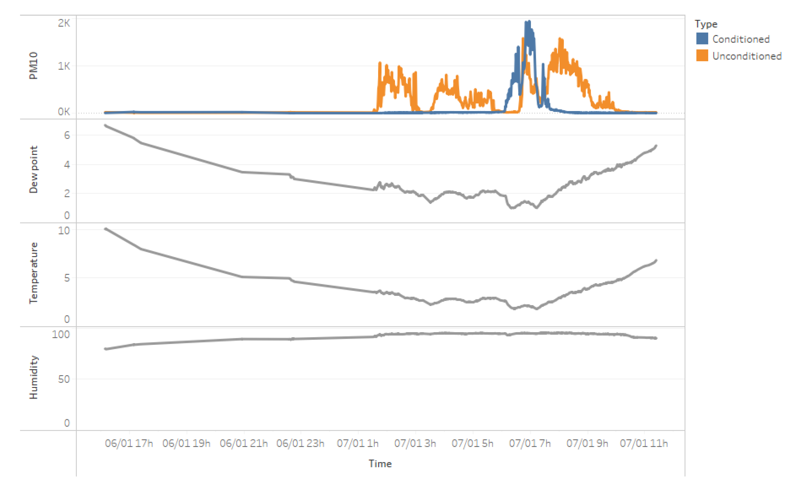
Congruence between measurements conducted with conditioned and unconditioned sensors can be classified into four classes: a) both sensors show relatively stable, comparable PM concentrations; b) conditioned sensor is stable, but unconditioned is not; c) both sensors are unstable, but unconditioned sensor is much worse; d) both sensors are unstable, but the conditioned sensor’s instability duration is much shorter. Following figures show examples for each category.
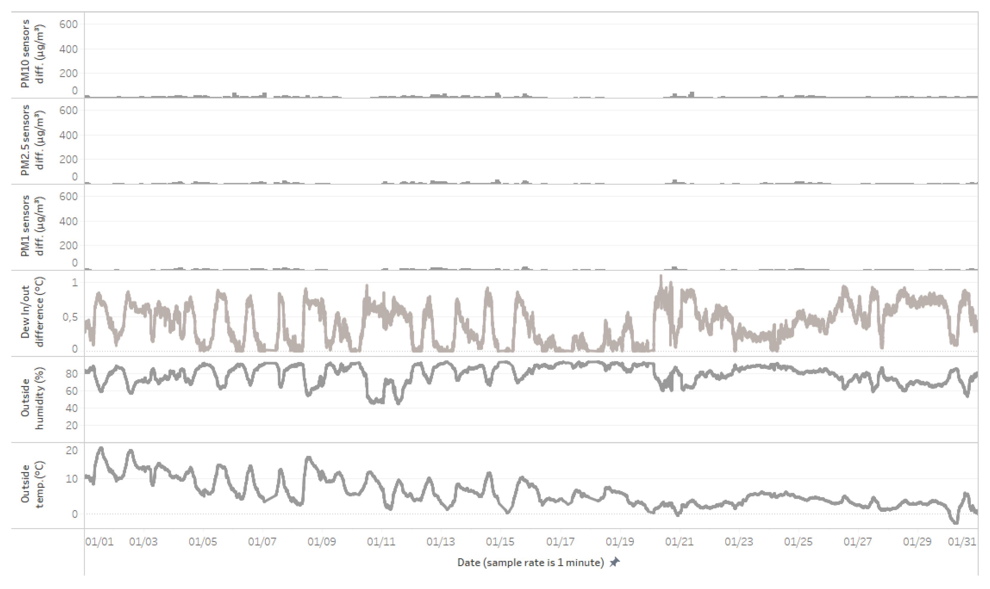
First identified class is characterized by a positive difference in dew points, where the outside air dew point is higher than the inside air dew point. In these situations, even when the relative humidity is high, both the conditioned and unconditioned sensors can measure comparable values. This indicates that when the outside air temperature is higher than the conditioned air temperature, and the dew point is not low, the sensors can provide stable and reliable measurements despite the high relative humidity, as shown in
Figure 11.
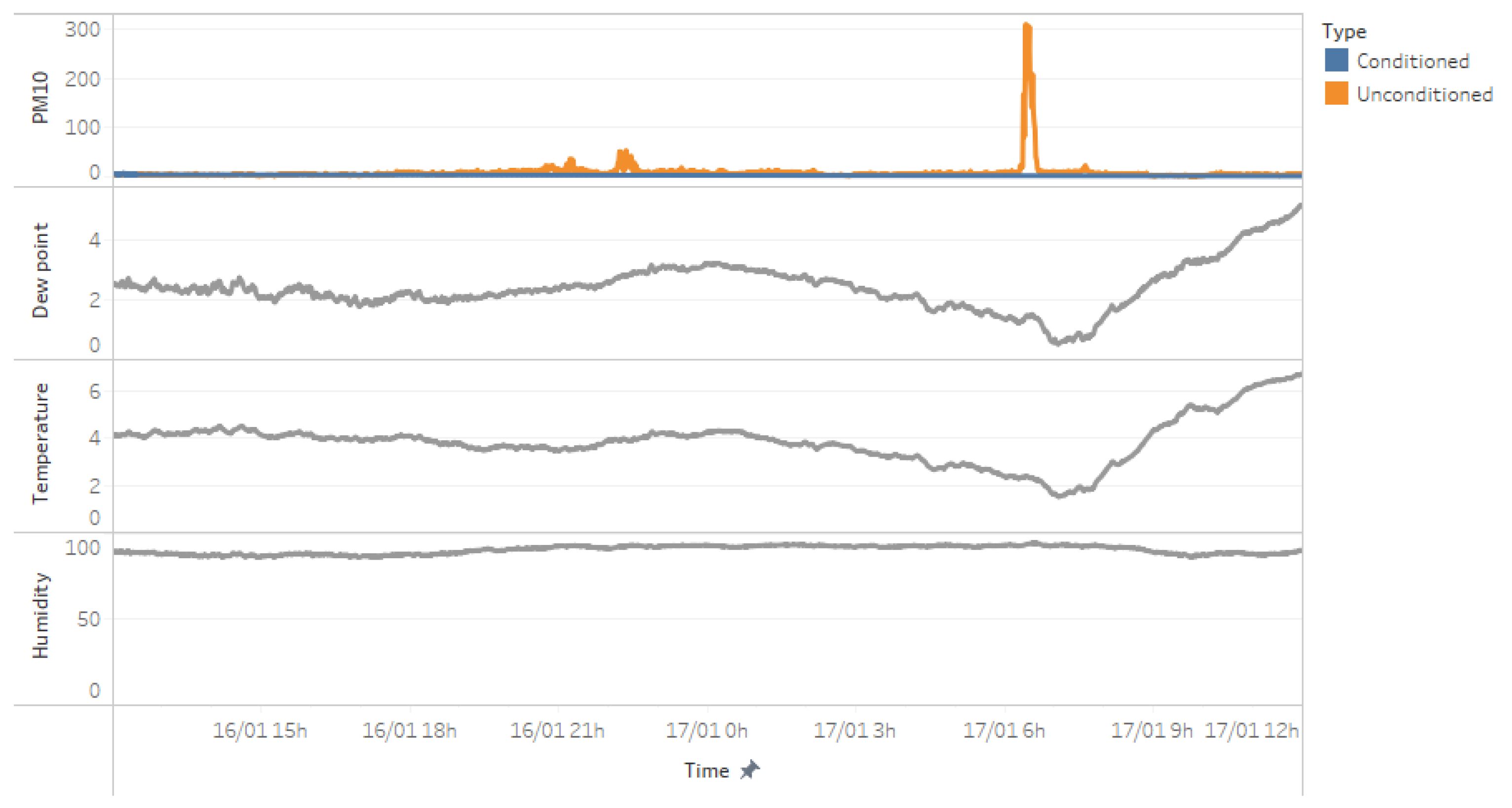
In the second class of congruence, the conditioned sensor maintains stable measurements, while the unconditioned sensor exhibits instability, as illustrated in
Figure 12. This suggests that the conditioning of the air effectively mitigates the influence of high relative humidity, allowing the conditioned sensor to provide reliable data even when the unconditioned sensor is affected by the environmental conditions.
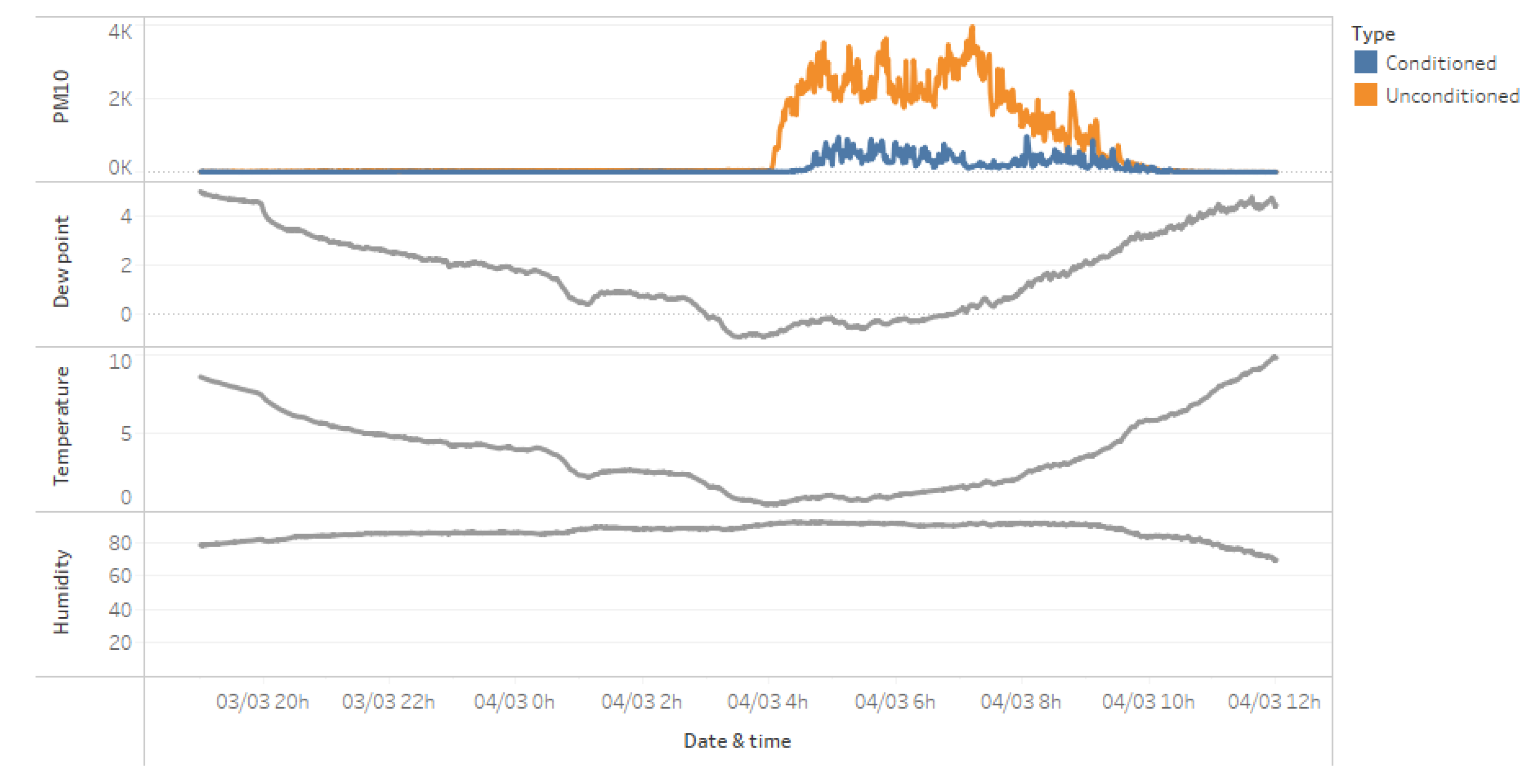
The third class represents a more extreme scenario, where both the conditioned and unconditioned sensors show instability. However, as shown in
Figure 13, the conditioned sensor exhibits a much smaller measurement instability compared to the unconditioned sensor. This indicates that the conditioning of the air helps to reduce the impact of high relative humidity, even when both sensors are affected to some degree.
The final class of congruence includes situations where both sensors show instability, but the duration of the conditioned sensor's instability is much shorter than the unconditioned sensor's. As illustrated in
Figure 14, the conditioned sensor is only unstable during steep dew point decreases, while the unconditioned sensor remains unstable for a longer period. This suggests that the conditioning of the air helps to mitigate the effects of high relative humidity, particularly during rapid changes in environmental conditions.
These four classes of congruence demonstrate the effectiveness of the conditioned sensor in improving the reliability and accuracy of particulate matter measurements, especially for larger particles that are more sensitive to changes in relative humidity. The results show that the conditioning of the air can help mitigate the negative effects of high relative humidity on sensor performance, allowing for more stable and accurate measurements across a range of environmental conditions.
Furthermore, the findings suggest that the conditioned sensor is particularly beneficial in situations where the outside air temperature is higher than the conditioned air temperature, and the dew point is not low. In these cases, the conditioned sensor is able to provide stable and reliable measurements, even when the unconditioned sensor is affected by the high relative humidity.
The ability of the conditioned sensor to maintain stability and accuracy during periods of high relative humidity is a significant advantage, as it allows for more reliable monitoring of particulate matter levels in real-world environments. This is especially important for applications where accurate and consistent data is crucial, such as air quality monitoring and environmental research.
Additionally, the insights gained from the different congruence classes can inform the development of more advanced data processing and correction algorithms, which can further enhance the performance of low-cost particulate matter sensors. By understanding the specific conditions under which sensor instability occurs, researchers and engineers can work to develop more robust and adaptive sensor systems that can reliably operate in a variety of environmental conditions.
Overall, the results of this study demonstrate the potential of using conditioned air inlets to improve the accuracy and reliability of low-cost particulate matter sensors, paving the way for more widespread and effective air quality monitoring solutions.
5. Conclusions and Future Work
This paper demonstrates the effectiveness of using air conditioning to improve the accuracy and reliability of low-cost particulate matter sensors (LCPMS) under different environmental conditions, particularly high relative humidity. The proposed novel inlet design, which incorporates strategically placed heaters to heat up the air, and drains to remove the condensed water, significantly mitigates the hygroscopic effects on particulate matter measurements, leading to more accurate readings of PM2.5 and PM10 levels.
The proposed design resulted in the improved stability and accuracy of the system. When the outside air temperature is higher than the conditioned air temperature, the system provides stable and reliable measurements despite the high relative humidity. Then, the paper shows that the air conditioning effectively mitigates the influence of high relative humidity, allowing the conditioned system to provide reliable data even when the unconditioned system is affected by the environmental conditions. Lastly, when the conditions are severe and both the conditioned and unconditioned systems show instability, the conditioned system’s measurements are less affected and sooner go back to the actual values.
To further validate the experiment results, extended field trials should be conducted in various environments with different climate profiles. Only in this way the long-term reliability and durability of the conditioned system can be assessed.
Author Contributions
Conceptualization, Zdravko Kunić and Leo Mršić; Data curation, Goran Đambić; Formal analysis, Zdravko Kunić, Leo Mršić and Goran Đambić; Funding acquisition, Leo Mršić; Methodology, Zdravko Kunić, Leo Mršić and Tomislav Ražov; Project administration, Tomislav Ražov; Visualization, Zdravko Kunić; Writing – original draft, Zdravko Kunić and Leo Mršić; Writing – review & editing, Zdravko Kunić, Leo Mršić, Goran Đambić and Tomislav Ražov.
Data Availability Statement
The data presented in this study are available on request from the corresponding author.
Acknowledgements
Research for this article has been supported by the Project 101056129 - Developing skills in Intellectual Property Rights Open Data for sustainability and circularity (IPR4SC) - ERASMUS-EDU-2021-PI-ALL-INNO
Conflicts of Interest
The authors declare that they have no conflicts of interest.
References
- Burnett, R.; Chen, H.; Szyszkowicz, M.; Fann, N.; Hubbell, B.; Pope, C.A., 3rd; Apte, J.S.; Brauer, M.; Cohen, A.; Weichenthal, S.; et al. Global estimates of mortality associated with long-term exposure to outdoor fine particulate matter. Proc. Natl. Acad. Sci. USA 2018, 115, 9592–9597. [Google Scholar] [CrossRef]
- World Health Organization: WHO global air quality guidelines: particulate matter (PM2.5 and PM10), ozone, nitrogen dioxide, sulfur dioxide and carbon monoxide. 2021. Available online: https://www.who.int/publications/i/item/9789240034228 (accessed on 25 March 2024).
- Air pollution: The invisible health threat. 2023. Available online: https://www.who.int/news-room/feature-stories/detail/air-pollution--the-invisible-health-threat (accessed on 25 March 2024).
- Air Quality. The EU sets air quality standards to protect human health and the environment. Available online: https://environment.ec.europa.eu/topics/air/air-quality_en (accessed on 25 March 2024).
- Kuula, J.; Timonen, H.; Niemi, J.V.; et al. Opinion: Insights into updating Ambient Air Quality Directive 2008/50/EC. Atmos. Chem. Phys. 2022, 22, 4801–4808. [Google Scholar] [CrossRef]
- Directive 2008/50/EC of the European Parliament and of the Council of 21 May 2008 on ambient air quality and cleaner air for Europe. 2008. Available online: https://eur-lex.europa.eu/eli/dir/2008/50/oj (accessed on 26 March 2024).
- Poupry, S.; Béler, C.; Medjaher, K. Development of a reliable measurement station for air quality monitoring based on low-cost sensors and active redundancy. IFAC-PapersOnLine 2022, 55, 7–12. [Google Scholar] [CrossRef]
- Arroyo, P.; Gómez-Suárez, J.; Suárez, J.I.; Lozano, J. Low-Cost Air Quality Measurement System Based on Electrochemical and PM Sensors with Cloud Connection. Sensors 2021, 21, 6228. [Google Scholar] [CrossRef]
- Alfano, B.; Barretta, L.; Del Giudice, A.; De Vito, S.; Di Francia, G.; Esposito, E.; Formisano, F.; Massera, E.; Miglietta, M.L.; Polichetti, T. A Review of Low-Cost Particulate Matter Sensors from the Depvelopers’ Perspectives. Sensors 2020, 20, 6819. [Google Scholar] [CrossRef]
- Wang, Y.; et al. Laboratory evaluation and calibration of three low-cost particle sensors for particulate matter measurement. Aerosol Sci. Technol. 2015, 49, 1063–1077. [Google Scholar] [CrossRef]
- Reece, S.; et al. "Low Cost Air Quality Sensor Deployment and Citizen Science: The Peñuelas Project", In Proceedings of the 4th International lectronic Conference on Sensors and Applications, Basel, Switzerland, 15–30 November 2017.
- de Ipiña, J.M.L.; Lopez, A.; Gazulla, A.; Aznar, G.; Belosi, F.; Koivisto, J.; Seddon, R.; Durałek, P.; Vavouliotis, A.; Koutsoukis, G.; et al. Field testing of low-cost particulate matter sensors for Digital Twin applications in nanomanufacturing processes. J. Phys. Conf. Ser. 2024, 2695, 012002. [Google Scholar] [CrossRef]
- European Committee for Standardization (CEN) 2023 Workplace exposure - Application of direct-reading low-cost sensors for measuring NOAA in the workplace (CEN/TC 137 WI=00137087).
- Bulot, F.M.J.; Ossont, S.J.; Morris, A.K.R.; Basford, P.J.; Easton, N.H.C.; Mitchell, H.L.; Foster, G.L.; Cox, S.J.; Loxham, M. Characterisation and calibration of low-cost PM sensors at high temporal resolution to reference-grade performance. Heliyon 2023, 9, 5. [Google Scholar] [CrossRef] [PubMed]
- Huang, J.; Kwan, M.P.; Cai, J.; Song, W.; Yu, C.; Kan, Z.; Yim, S.H.L. Field Evaluation and Calibration of Low-Cost Air Pollution Sensors for Environmental Exposure Research. Sensors 2022, 22, 2381. [Google Scholar] [CrossRef]
- Jiang, Y.X.; Zhu, X.L.; Chen, C.; Ge, Y.H.; Wang, W.D.; Zhao, Z.H.; Cai, J.; Kan, H.D. On-field test and data calibration of a low-cost sensor for fine particles exposure assessment. Ecotoxicol. Environ. Saf. 2021, 211, 111958. [Google Scholar] [CrossRef]
- Liang, L. Calibrating low-cost sensors for ambient air monitoring: Techniques, trends, and challenges. Environmental Research 2021, 197, 111163. [Google Scholar] [CrossRef] [PubMed]
- Liang, L.; Daniels, J. What Influences Low-cost Sensor Data Calibration?—A Systematic Assessment of Algorithms, Duration, and Predictor Selection. Aerosol and Air Quality Research 2022, 22, 220076. [Google Scholar] [CrossRef]
- Wang, Y.; Li, J.; Jing, H.; Zhang, Q.; Jiang, J.; Biswas, P. Laboratory evaluation and calibration of three low-cost particle sensors for particulate matter measurement. Aerosol Sci. Technol. 2015, 49, 1063–1077. [Google Scholar] [CrossRef]
- Sousan, S.; Koehler, K.; Thomas, G.; Park, J.H.; Hillman, M.; Halterman, A.; Peters, T.M. Inter-comparison of low-cost sensors for measuring the mass concentration of occupational aerosols. Aerosol Sci. Technol. 2016, 50, 462–473. [Google Scholar]
- Omidvarborna, H.; Kumar, P.; Tiwari, A. Envilution™ chamber for performance evaluation of low-cost sensors. Atmos. Environ. 2020, 223, 117264. [Google Scholar] [CrossRef]
- Crilley, L.R.; Shaw, M.; Pound, R.; Kramer, L.J.; Price, R.; Young, S.; Lewis, A.C.; Pope, F.D. Evaluation of a low-cost optical particle counter (Alphasense OPC-N2) for ambient air monitoring. Atmos. Meas. Tech. 2018, 709–720. [Google Scholar] [CrossRef]
- Zheng, T. Field evaluation of low-cost particulate matter sensors in high and low concentration environments. Ph.D. Thesis, Duke University, Durham, NC, USA, 2018. [Google Scholar]
- Tejada, R. Predicting Influence of Relative Humidity (RH) on Low-Cost Particulate Matter Sensors (LCPMSs) with Empirically Derived Single-Parameter for Hygroscopicity based on K-Kohler Theory. Retrieved from the University of Minnesota Digital Conservancy. 2022. https://hdl.handle.net/11299/252493.
- Petters, M.D.; Kreidenweis, S.M. A single parameter representation of hygroscopic growth and cloud condensation nucleus activity. Atmos. Chem. Phys. 2007, 11. [Google Scholar] [CrossRef]
- Raysoni, A.U.; Pinakana, S.D.; Mendez, E.; Wladyka, D.; Sepielak, K.; Temby, O. A Review of Literature on the Usage of Low-Cost Sensors to Measure Particulate Matter. Earth 2023, 4, 168–186. [Google Scholar] [CrossRef]
- Di Antonio, A.; Popoola, O.A.M.; Ouyang, B.; Saffell, J.; Jones, R.L. Developing a Relative Humidity Correction for Low-Cost Sensors Measuring Ambient Particulate Matter. Sensors 2018, 18. [Google Scholar] [CrossRef] [PubMed]
- Liu, Y.; Yang, Z.; Desyaterik, Y.; Gassman, P.L.; Wang, H.; Laskin, A. Hygroscopic Behavior of Substrate-Deposited Particles Studied by micro-FT-IR Spectroscopy and Complementary Methods of Particle Analysis. Anal. Chem. 2008, 80, 633–642. [Google Scholar] [CrossRef]
- Jayaratne, R.; Liu, X.; Thai, P.; Dunbabin, M.; Morawska, L. The influence of humidity on the performance of a low-cost air particle mass sensor and the effect of atmospheric fog’, Atmospheric Measurement Techniques, vol. 11, no. 8, pp. 4883–4890, 2018.
- Vajs, I.; Drajic, D.; Gligoric, N.; Radovanovic, I.; Popovic, I. Developing Relative Humidity and Temperature Corrections for Low-Cost Sensors Using Machine Learning. Sensors 2021, 21, 3338. [Google Scholar] [CrossRef] [PubMed]
- Kaur, K.; Kelly, K.E. Laboratory evaluation of the Alphasense OPC-N3, and the Plantower PMS5003 and PMS6003 sensors. J. Aerosol Sci. 2023, 171, 106181. [Google Scholar] [CrossRef]
- Won, W.S.; Oh, R.; Lee, W.; et al. Hygroscopic properties of particulate matter and effects of their interactions with weather on visibility. Sci. Rep. 2021, 11, 16401. [Google Scholar] [CrossRef] [PubMed]
- Alduchov, O.A.; Eskridge, R.E. Improved Magnus Form Approximation of Saturation Vapor Pressure. J. Appl. Meteorol. Climatol. 1996, 35, 601–609. [Google Scholar] [CrossRef]
- Carslaw, K.S. (Ed.) ‘Chapter 5 - Aerosol processes’. In Aerosols and Climate, Elsevier: Amsterdam, The Netherlands, 2022; pp. 135–185.
Figure 1.
Novel LCPMS-based indicative station.
Figure 1.
Novel LCPMS-based indicative station.
Figure 2.
Main parts of the particle matter measurement subsystem.
Figure 2.
Main parts of the particle matter measurement subsystem.
Figure 3.
Detailed view of the particle matter measurement subsystem.
Figure 3.
Detailed view of the particle matter measurement subsystem.
Figure 4.
Subsystem for removing condensed water from the intake path.
Figure 4.
Subsystem for removing condensed water from the intake path.
Figure 5.
Relationship between relative humidity and temperature.
Figure 5.
Relationship between relative humidity and temperature.
Figure 6.
Experiment setup.
Figure 6.
Experiment setup.
Figure 7.
The incidence relationships of the relative humidity and the difference between unconditioned/conditioned sensors for measuring concentrations of a) PM1, b) PM2.5, and c) PM10 respectively.
Figure 7.
The incidence relationships of the relative humidity and the difference between unconditioned/conditioned sensors for measuring concentrations of a) PM1, b) PM2.5, and c) PM10 respectively.
Figure 8.
The absolute differences in the sampled values between the conditioned and unconditioned sensors over the entire experimental period for a) PM1, b) PM2.5, and c) PM10 respectively.
Figure 8.
The absolute differences in the sampled values between the conditioned and unconditioned sensors over the entire experimental period for a) PM1, b) PM2.5, and c) PM10 respectively.
Figure 9.
Comparative overview of conditioned/unconditioned sensors’ readings difference, dew point outside/inside difference, outside humidity and outside temperature in January 2023.
Figure 9.
Comparative overview of conditioned/unconditioned sensors’ readings difference, dew point outside/inside difference, outside humidity and outside temperature in January 2023.
Figure 10.
The incidence relationships of the dew point difference between inside/outside air and the difference between unconditioned/conditioned sensors for measuring concentrations of a) PM1, b) PM2.5, and c) PM10 respectively.
Figure 10.
The incidence relationships of the dew point difference between inside/outside air and the difference between unconditioned/conditioned sensors for measuring concentrations of a) PM1, b) PM2.5, and c) PM10 respectively.
Figure 11.
Both sensors are stable, regardless of high humidity, due to dew point higher than actual temperature. This visualization is similar to
Figure 9, but samples with negative values of dew in/out difference are filtered out.
Figure 11.
Both sensors are stable, regardless of high humidity, due to dew point higher than actual temperature. This visualization is similar to
Figure 9, but samples with negative values of dew in/out difference are filtered out.
Figure 12.
An example of a situation in which conditioned sensor measures stable values, while unconditioned sensor is unstable.
Figure 12.
An example of a situation in which conditioned sensor measures stable values, while unconditioned sensor is unstable.
Figure 13.
Both sensors are unstable, but conditioned sensor is better.
Figure 13.
Both sensors are unstable, but conditioned sensor is better.
Figure 14.
Both sensors are unstable, but conditioned sensor is unstable shorter period of time.
Figure 14.
Both sensors are unstable, but conditioned sensor is unstable shorter period of time.
|
Disclaimer/Publisher’s Note: The statements, opinions and data contained in all publications are solely those of the individual author(s) and contributor(s) and not of MDPI and/or the editor(s). MDPI and/or the editor(s) disclaim responsibility for any injury to people or property resulting from any ideas, methods, instructions or products referred to in the content. |
© 2024 by the authors. Licensee MDPI, Basel, Switzerland. This article is an open access article distributed under the terms and conditions of the Creative Commons Attribution (CC BY) license (http://creativecommons.org/licenses/by/4.0/).
