Submitted:
30 July 2024
Posted:
30 July 2024
You are already at the latest version
Abstract
Keywords:
1. Introduction
2. Hydrothermal-Based Co-Firing System
2.1. Governing Equations
2.2. Turbulence
2.3. Radiation
2.4. Reaction Mechanisms Particle Phases
2.5 Reaction Mechanisms Gas Phase
3. Materials
4. Boundary condition
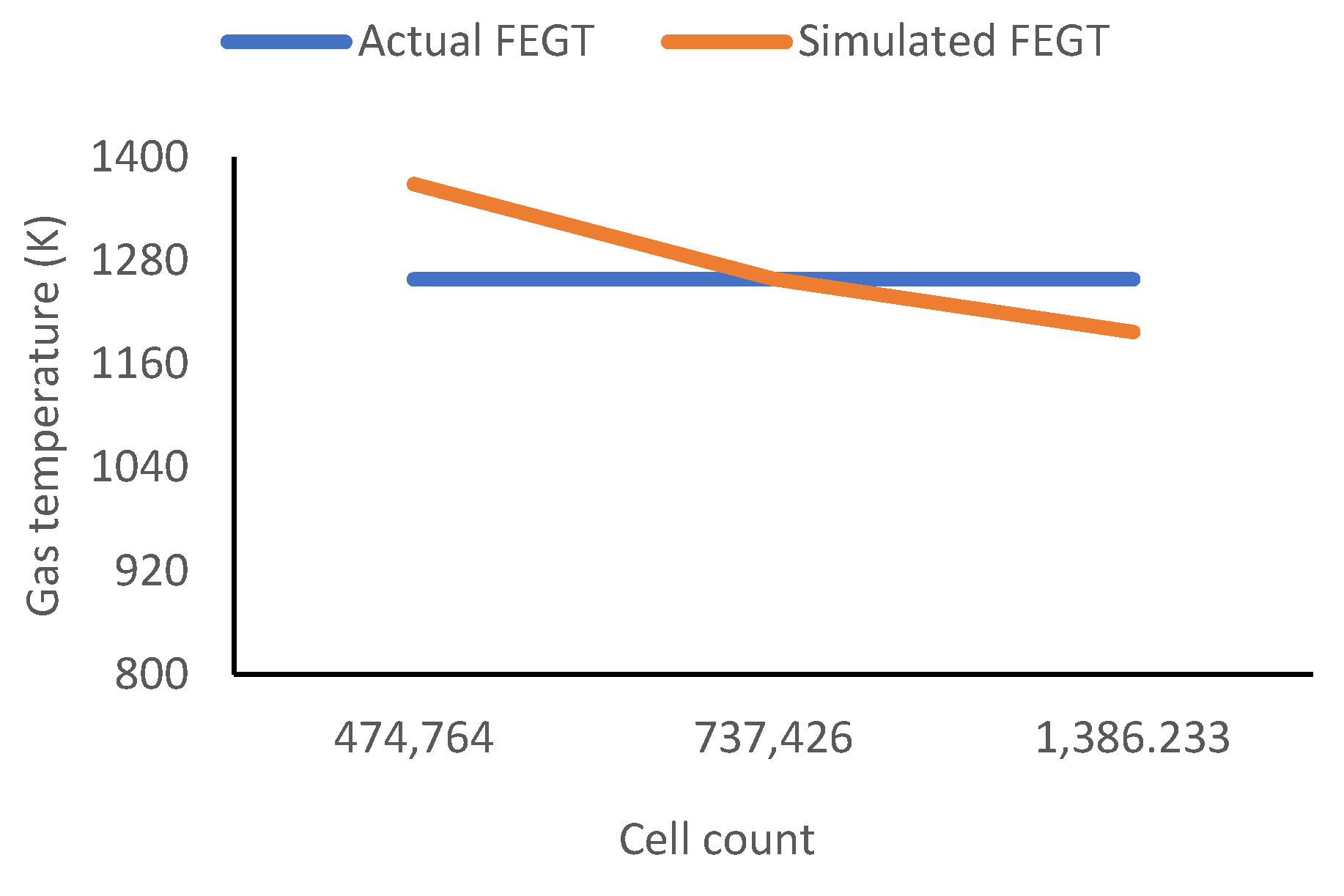
5. Grid Independence and Validating the Computational Fluid Dynamic (CFD) Simulation
6. Results and discussion
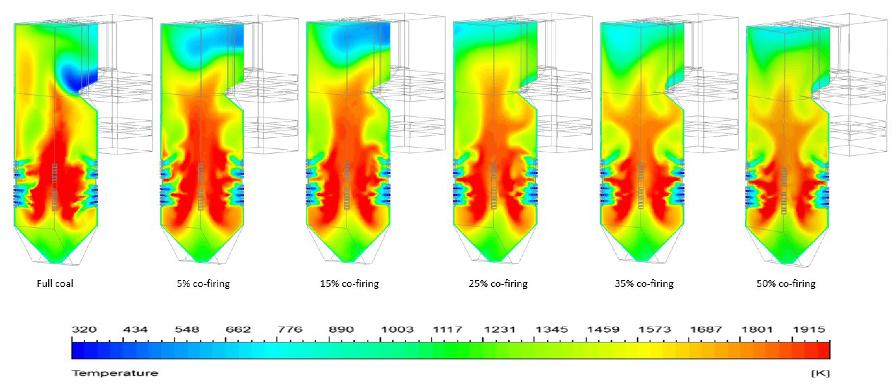
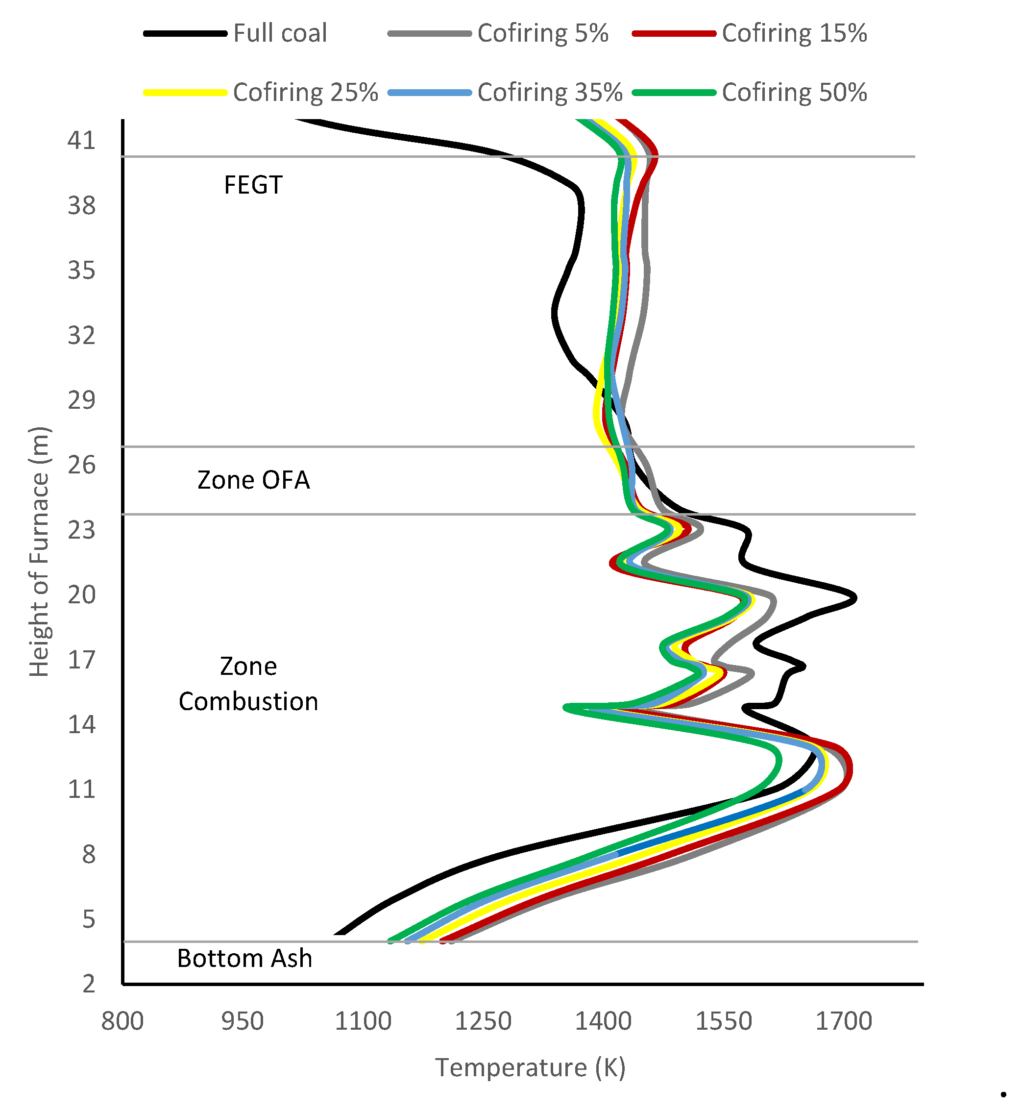
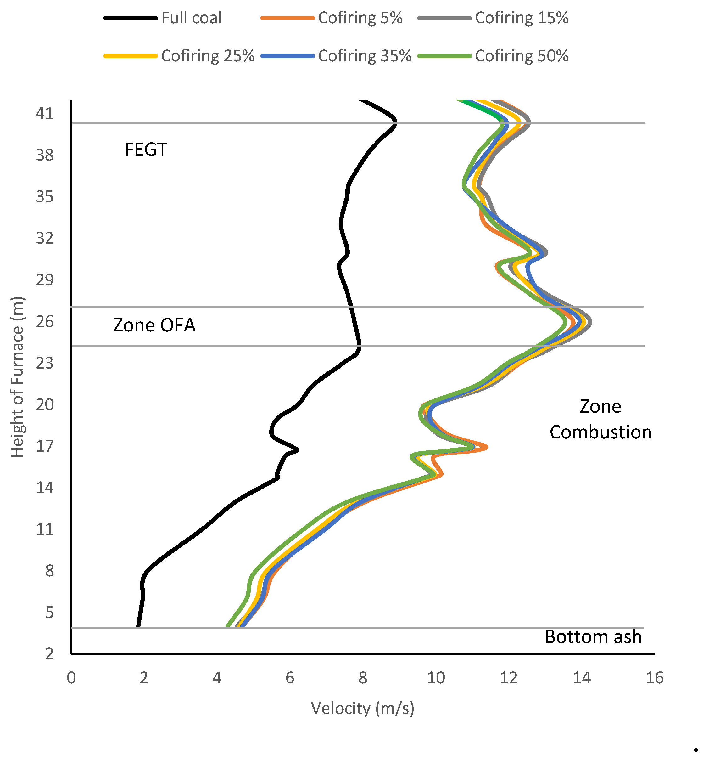
6.1. Effects of Co-Firing HT-FRD on Distribution Temperature
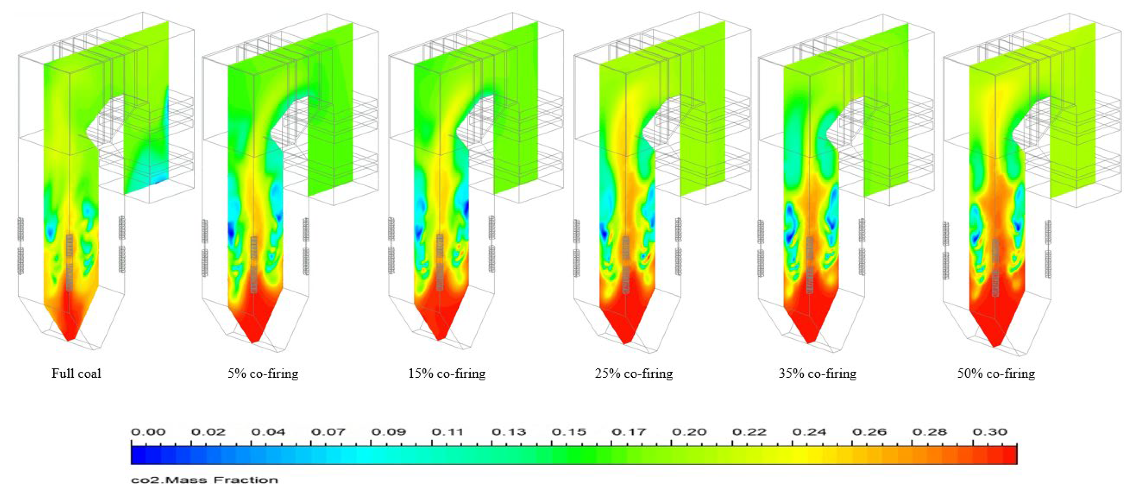
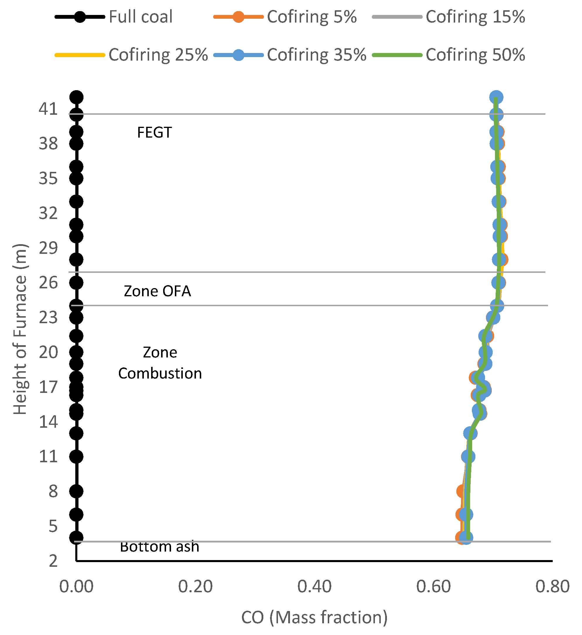
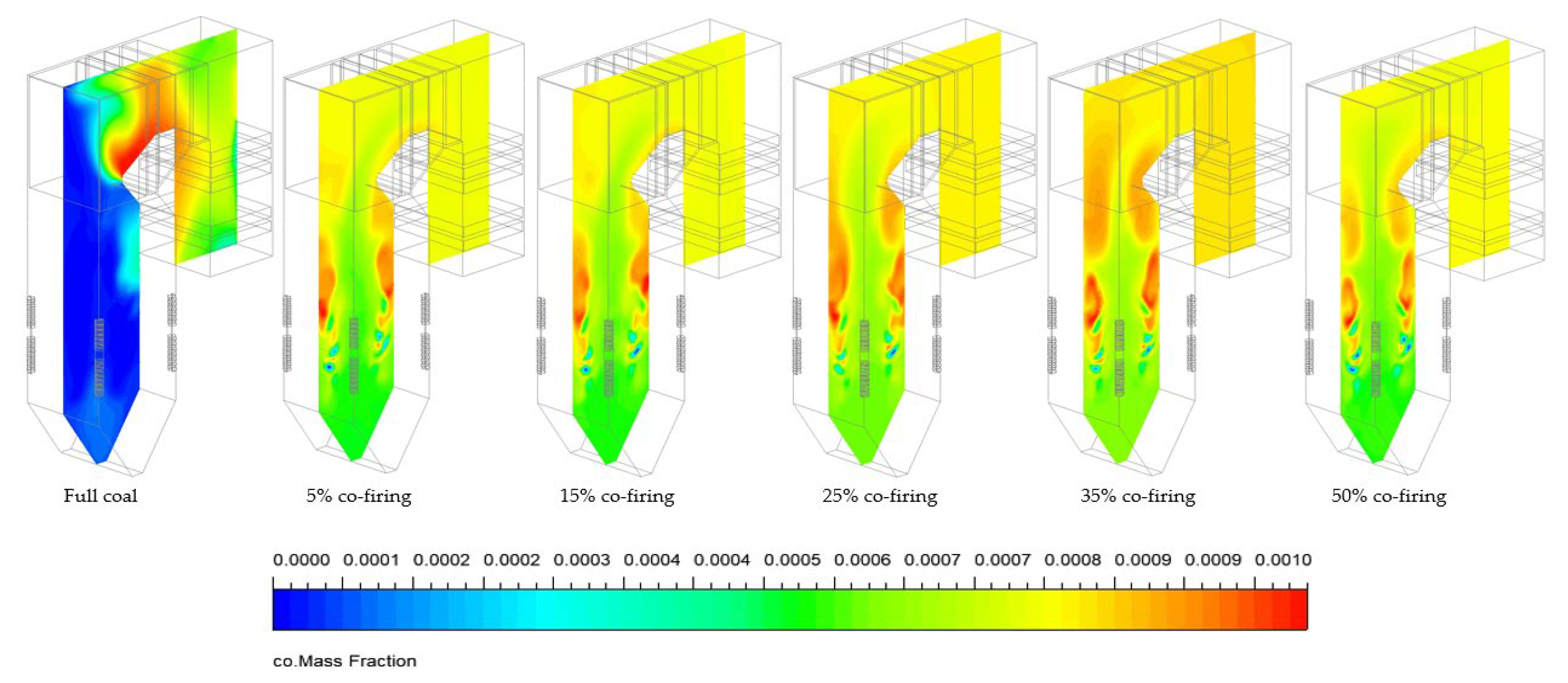
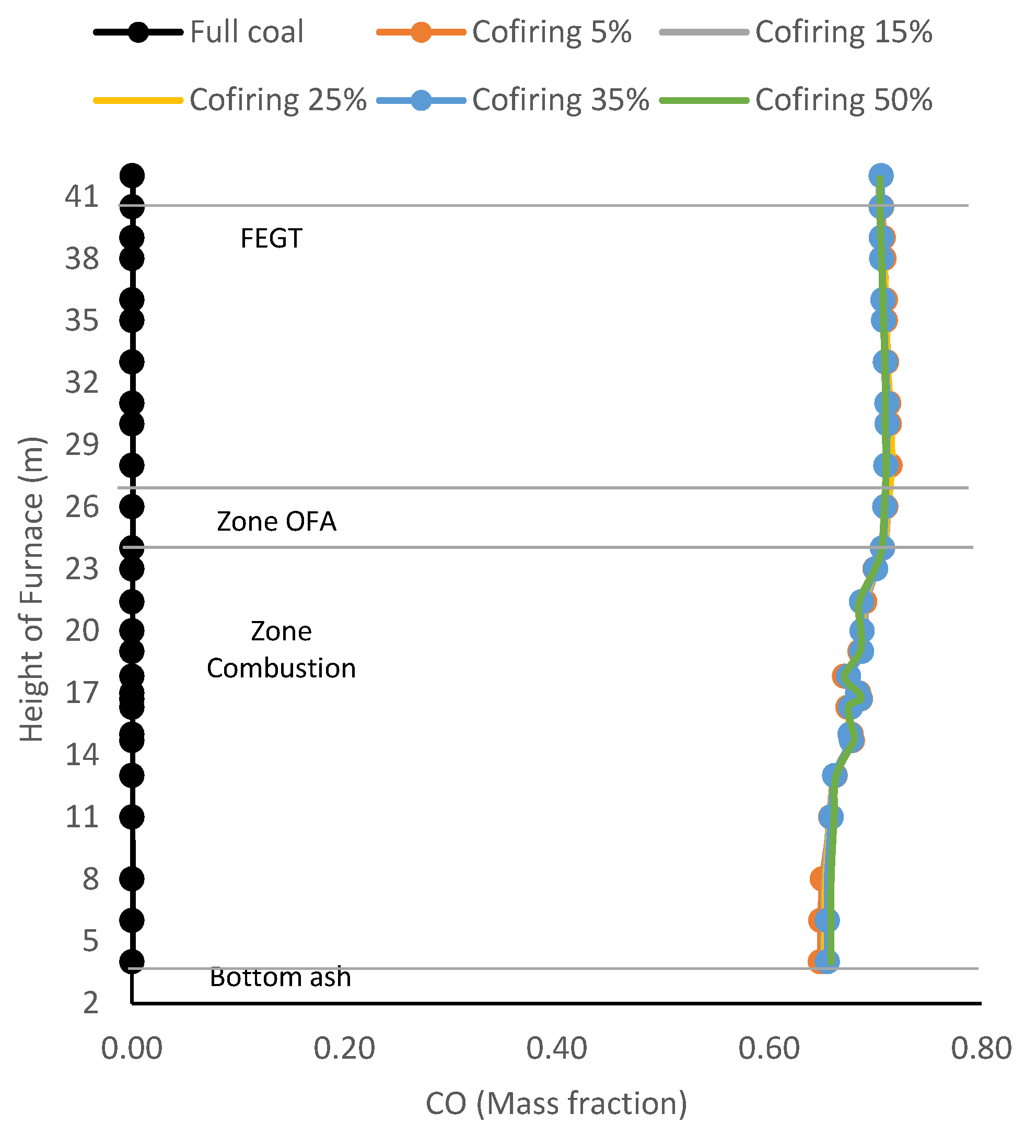
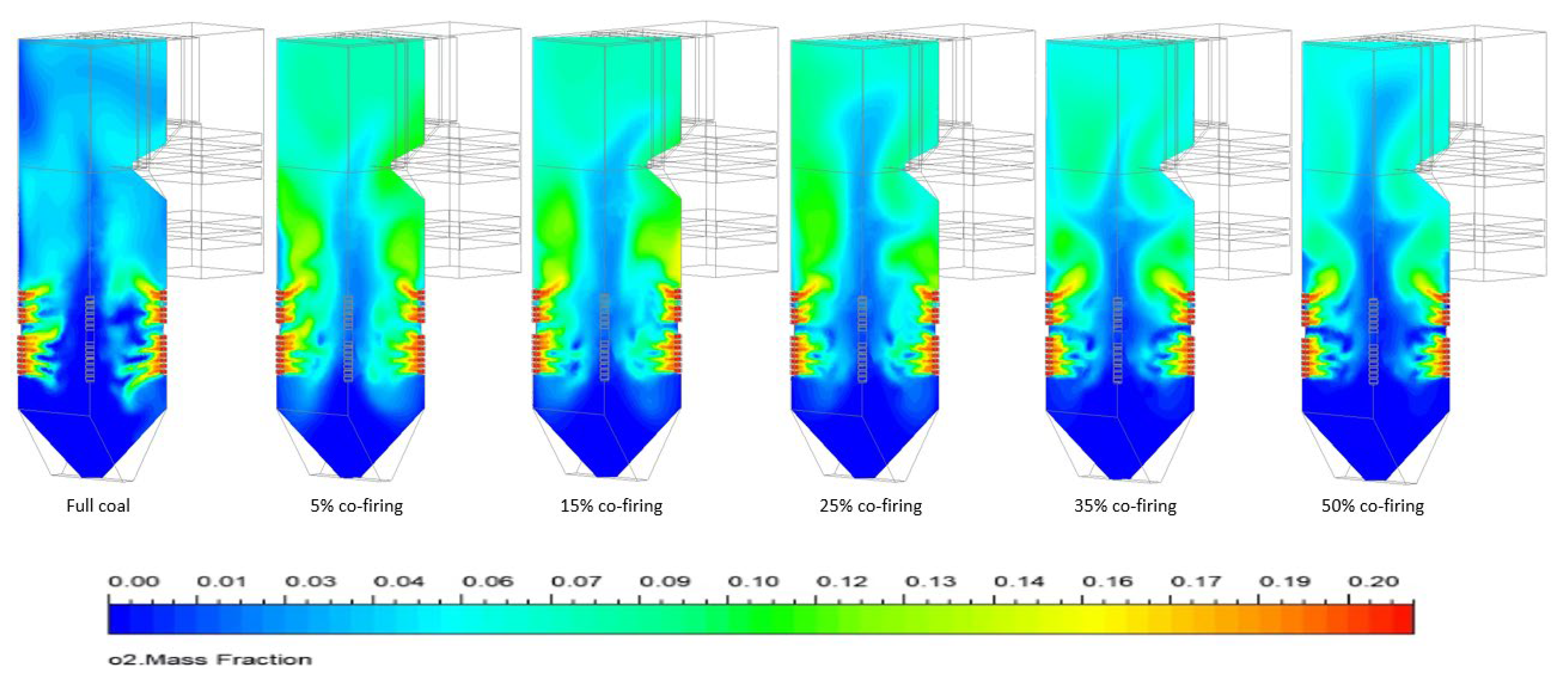
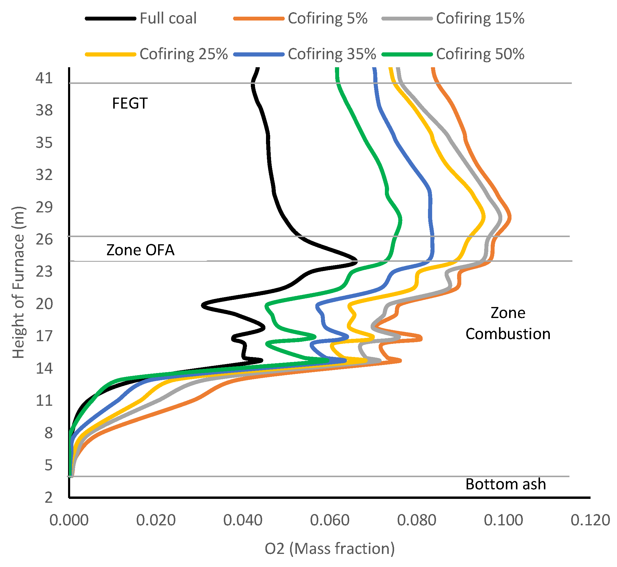
6.3. Effects of Co-Firing HT-FRD on Gas Emission CO2, CO, and O2
7. Conclusions
Author Contributions
Funding
Institutional Review Board Statement
Informed Consent Statement
Data Availability Statement
Acknowledgments
Conflicts of Interest
Abbreviation
| Abbreviation | Meaning |
| CFD | computational fluid dynamics |
| CO2 | carbon dioxide |
| CO | carbon monoxide |
| FEGT | furnace exit gas temperature |
| HT-FRD | hydrothermal palm frond |
| OFA | overfire air |
| O2 | oxygen |
| RANS | Reynolds average Navier-Stokes |
| PA | primary air |
| SA | secondary air |
References
- PLN, ‘menteri energi dan sumber daya mineral republik indonesia keputusan menteri energi dan sumber daya mineral republik indonesia’, 2023.
- Aziz, M.; Oda, T.; Kashiwagi, T. Energy-Efficient Low Rank Coal Drying Based on Enhanced Vapor Recompression Technology. Dry. Technol. 2014, 32, 1621–1631. [Google Scholar] [CrossRef]
- Aziz, M.; Kansha, Y.; Kishimoto, A.; Kotani, Y.; Liu, Y.; Tsutsumi, A. Advanced energy saving in low rank coal drying based on self-heat recuperation technology. Fuel Process. Technol. 2012, 104, 16–22. [Google Scholar] [CrossRef]
- Liu, Y.; Aziz, M.; Kansha, Y.; Tsutsumi, A. A novel exergy recuperative drying module and its application for energy-saving drying with superheated steam. Chem. Eng. Sci. 2013, 100, 392–401. [Google Scholar] [CrossRef]
- Aziz, M.; Oda, T.; Kashiwagi, T. Design and Analysis of Energy-Efficient Integrated Crude Palm Oil and Palm Kernel Oil Processes. J. Jpn. Inst. Energy 2015, 94, 143–150. [Google Scholar] [CrossRef]
- Aziz, M.; Prawisudha, P.; Prabowo, B.; Budiman, B.A. Integration of energy-efficient empty fruit bunch drying with gasification/combined cycle systems. Appl. Energy 2015, 139, 188–195. [Google Scholar] [CrossRef]
- Basiron, Y. Palm oil production through sustainable plantations. Eur. J. Lipid Sci. Technol. 2007, 109, 289–295. [Google Scholar] [CrossRef]
- Darmawan, A.; Prida Putra, H.; Milky Kuswa, F.; Sholeh, M.; Aziz, M. Combustion characteristics during cofiring of palm empty fruit bunch, palm frond with bituminous coal. 2021.
- Hariana; Prabowo; Hilmawan, E. ; Kuswa, F.M.; Darmawan, A.; Aziz, M. A comprehensive evaluation of cofiring biomass with coal and slagging-fouling tendency in pulverized coal-fired boilers. Ain Shams Eng. J. 2023, 14, 102001. [Google Scholar] [CrossRef]
- S. Ihsan, Prabowo, W. A. Widodo, and I. N. A. Adi Saputra, ‘Numerical Investigation Effect of the addition of palm fronds on the burning of coal-fired boilers tangentially. in 2023 International Conference on Advanced Mechatronics, Intelligent Manufacture and Industrial Automation, ICAMIMIA 2023 - Proceedings, Institute of Electrical and Electronics Engineers Inc., 2023, pp. 261–265. [CrossRef]
- Gubba, S.; Ma, L.; Pourkashanian, M.; Williams, A. Influence of particle shape and internal thermal gradients of biomass particles on pulverised coal/biomass co-fired flames. Fuel Process. Technol. 2011, 92, 2185–2195. [Google Scholar] [CrossRef]
- Aziz, M.; Budianto, D.; Oda, T. Computational Fluid Dynamic Analysis of Co-Firing of Palm Kernel Shell and Coal. Energies 2016, 9, 137. [Google Scholar] [CrossRef]
- Fernando, R. Cofiring high ratios of biomass with coal. 2012.
- Koppejan, J.; Bv, B.; Kwant, K. Task 32 Biomass Combustion and Cofiring Task 32 Biomass Combustion and Cofiring Operating Agent. 2016.
- Griffifin, W.M.; Michalek, J.; Matthews, H.S.; Hassan, M.N.A. Availability of biomass residues for co-firing in peninsular Malaysia: Implications for cost and GHG emissions in the electricity sector. Energies 2014, 7, 804–823. [Google Scholar] [CrossRef]
- Novianti, S.; Nurdiawati, A.; Zaini, I.N.; Sumida, H.; Yoshikawa, K. Hydrothermal treatment of palm oil empty fruit bunches: an investigation of the solid fuel and liquid organic fertilizer applications. Biofuels 2016, 7, 627–636. [Google Scholar] [CrossRef]
- Lucian, M.; Fiori, L. Hydrothermal Carbonization of Waste Biomass: Process Design, Modeling, Energy Efficiency and Cost Analysis. Energies 2017, 10, 211. [Google Scholar] [CrossRef]
- Zaini, I.N.; Novianti, S.; Nurdiawati, A.; Irhamna, A.R.; Aziz, M.; Yoshikawa, K. Investigation of the physical characteristics of washed hydrochar pellets made from empty fruit bunch. Fuel Process. Technol. 2017, 160, 109–120. [Google Scholar] [CrossRef]
- Saqib, N.U.; Baroutian, S.; Sarmah, A.K. Physicochemical, structural and combustion characterization of food waste hydrochar obtained by hydrothermal carbonization. Bioresour. Technol. 2018, 266, 357–363. [Google Scholar] [CrossRef] [PubMed]
- Parshetti, G.K.; Hoekman, S.K.; Balasubramanian, R. Chemical, structural and combustion characteristics of carbonaceous products obtained by hydrothermal carbonization of palm empty fruit bunches. Bioresour. Technol. 2013, 135, 683–689. [Google Scholar] [CrossRef] [PubMed]
- Xiao, L.-P.; Shi, Z.-J.; Xu, F.; Sun, R.-C. Hydrothermal carbonization of lignocellulosic biomass. Bioresour. Technol. 2012, 118, 619–623. [Google Scholar] [CrossRef] [PubMed]
- Ibbett, R.; Gaddipati, S.; Davies, S.; Hill, S.; Tucker, G. The mechanisms of hydrothermal deconstruction of lignocellulose: New insights from thermal–analytical and complementary studies. Bioresour. Technol. 2011, 102, 9272–9278. [Google Scholar] [CrossRef] [PubMed]
- Román, S.; Nabais, J.; Laginhas, C.; Ledesma, B.; González, J. Hydrothermal carbonization as an effective way of densifying the energy content of biomass. Fuel Process. Technol. 2011, 103, 78–83. [Google Scholar] [CrossRef]
- Liu, Z.; Quek, A.; Hoekman, S.K.; Balasubramanian, R. Production of solid biochar fuel from waste biomass by hydrothermal carbonization. Fuel 2013, 103, 943–949. [Google Scholar] [CrossRef]
- Ma, L.; Gharebaghi, M.; Porter, R.; Pourkashanian, M.; Jones, J.; Williams, A. Modelling methods for co-fired pulverised fuel furnaces. Fuel 2009, 88, 2448–2454. [Google Scholar] [CrossRef]
- Gera, D.; Mathur, M.P.; Freeman, M.C.; Robinson, A. Effect of Large Aspect Ratio of Biomass Particles on Carbon Burnout in a Utility Boiler. Energy Fuels 2002, 16, 1523–1532. [Google Scholar] [CrossRef]
- Backreedy, R.; Fletcher, L.; Jones, J.; Ma, L.; Pourkashanian, M.; Williams, A. Co-firing pulverised coal and biomass: a modeling approach. Proc. Combust. Inst. 2005, 30, 2955–2964. [Google Scholar] [CrossRef]
- Pallarés, J.; Gil, A.; Cortés, C.; Herce, C. Numerical study of co-firing coal and Cynara cardunculus in a 350 MWe utility boiler. Fuel Process. Technol. 2009, 90, 1207–1213. [Google Scholar] [CrossRef]
- Yin, C.; Rosendahl, L.; Kær, S.K.; Condra, T.J. Use of numerical modeling in design for co-firing biomass in wall-fired burners. Chem. Eng. Sci. 2004, 59, 3281–3292. [Google Scholar] [CrossRef]
- Agraniotis, M.; Nikolopoulos, N.; Nikolopoulos, A.; Grammelis, P.; Kakaras, E. Numerical investigation of Solid Recovered Fuels’ co-firing with brown coal in large scale boilers – Evaluation of different co-combustion modes. Fuel 2010, 89, 3693–3709. [Google Scholar] [CrossRef]
- Bhuiyan, A.A.; Naser, J. CFD modelling of co-firing of biomass with coal under oxy-fuel combustion in a large scale power plant. Fuel 2015, 159, 150–168. [Google Scholar] [CrossRef]
- Bhuiyan, A.A.; Karim, M.R.; Naser, J. Modeling of Solid and Bio-Fuel Combustion Technologies. in Thermofluid Modeling for Energy Efficiency Applications, Elsevier Inc.: Amsterdam, The Netherlands, 2016; pp. 259–309. [CrossRef]
- Ranade, V.V.; Gupta, D.F. Computational Modeling of Pulverized Coal Fired Boilers. 2015.
- Aziz, M.; Oda, T.; Kashiwagi, T. Advanced Energy Harvesting from Macroalgae—Innovative Integration of Drying, Gasification and Combined Cycle. Energies 2014, 7, 8217–8235. [Google Scholar] [CrossRef]
- Li, W.; Guo, J.; Cheng, H.; Wang, W.; Dong, R. Two-phase anaerobic digestion of municipal solid wastes enhanced by hydrothermal pretreatment: Viability, performance and microbial community evaluation. Appl. Energy 2017, 189, 613–622. [Google Scholar] [CrossRef]
- Darmawan, A.; Budianto, D.; Aziz, M.; Tokimatsu, K. Retrofitting existing coal power plants through cofiring with hydrothermally treated empty fruit bunch and a novel integrated system. Appl. Energy 2017, 204, 1138–1147. [Google Scholar] [CrossRef]
- Xu, W.; Niu, Y.; Tan, H.; Wang, D.; Du, W.; Hui, S. A New Agro/Forestry Residues Co-Firing Model in a Large Pulverized Coal Furnace: Technical and Economic Assessments. Energies 2013, 6, 4377–4393. [Google Scholar] [CrossRef]
- Saputra, I.N.A.A. ; Prabowo; Setiyawan, A.; Kusuma, I.G.B.W.; Ihsan, S.; Hariana. 3D Simulation Combustion Characteristics Of EFB Biomass Co-Firing With Low Rank Coal In Pulverized Coal Boiler. in 2023 International Conference on Advanced Mechatronics, Intelligent Manufacture and Industrial Automation, ICAMIMIA 2023 - Proceedings, Institute of Electrical and Electronics Engineers Inc., 2023, pp. 370–374. [CrossRef]
- Karampinis, E.; Grammelis, P.; Agraniotis, M.; Violidakis, I.; Kakaras, E. Co--firing of biomass with coal in thermal power plants: technology schemes, impacts, and future perspectives. WIREs Energy Environ. 2013, 3, 384–399. [Google Scholar] [CrossRef]
- Wang, Y.; Yan, L. CFD Studies on Biomass Thermochemical Conversion. Int. J. Mol. Sci. 2008, 9, 1108–1130. [Google Scholar] [CrossRef]
- Bhuiyan, A.A.; Naser, J. Computational modelling of co-firing of biomass with coal under oxy-fuel condition in a small scale furnace. Fuel 2015, 143, 455–466. [Google Scholar] [CrossRef]
- Agosta, V.D. DAVID MIGDAL 1 A Source Flow Model for Continuum Gas-Particle Flow. 1967. Available Online: http://www.asme.
- Budianto, D.; Aziz, M.; Cahyadi; Oda, T. Numerical Investigation of Co-Firing of Palm Kernel Shell into Pulverized Coal Combustion. J. Jpn. Inst. Energy 2016, 95, 605–614. [Google Scholar] [CrossRef]
- Bhuiyan, A.A.; Naser, J. CFD modelling of co-firing of biomass with coal under oxy-fuel combustion in a large scale power plant. Fuel 2015, 159, 150–168. [Google Scholar] [CrossRef]
- Anderson, J.D. Governing Equations of Fluid Dynamics. 2009.
- Launder, B.I.S.B.E. Application Of the Energy-Dissipation Model Of Turbulence to the Calculation of Flow Near A Spinning Disc. Lett. Heat Mass Transf. 1974, 1, 131–138. [Google Scholar] [CrossRef]
- Majda, A.; Sethian, J. The Derivation and Numerical Solution of the Equations for Zero Mach Number Combustion. Combust. Sci. Technol. 1985, 42, 185–205. [Google Scholar] [CrossRef]
- Tabet, F.; Gökalp, I. Review on CFD based models for co-firing coal and biomass. Renew. Sustain. Energy Rev. 2015, 51, 1101–1114. [Google Scholar] [CrossRef]
- Jiang, Y.; Park, K.-H.; Jeon, C.-H. Feasibility Study of Co-Firing of Torrefied Empty Fruit Bunch and Coal through Boiler Simulation. Energies 2020, 13, 3051. [Google Scholar] [CrossRef]
- Oevermann, M.; Gerber, S.; Behrendt, F. Euler–Lagrange/DEM simulation of wood gasification in a bubbling fluidized bed reactor. Particuology 2009, 7, 307–316. [Google Scholar] [CrossRef]
- Smith, J.D.; Suo-Antilla, A.; Sreedharan, V. Transient LES based CFD modeling of coal-biomass co-firing combustion. Fuel Process. Technol. 2019, 193, 187–196. [Google Scholar] [CrossRef]
- Vesilind, P. The Rosin-Rammler particle size distribution. Resour. Recover. Conserv. 1980, 5, 275–277. [Google Scholar] [CrossRef]
- Yin, C.; Kaer, S.K.; Rosendahl, L.; Hvid, S.L. MODELING OF PULVERIZED COAL AND BIOMASS CO-FIRING IN A 150 KW SWIRLING-STABILIZED BURNER AND EXPERIMENTAL VALIDATION’.
- Rahman, M.N.; Othman, N.F.B. A Numerical Model for Ash Deposition Based on Actual Operating Conditions of a 700 MW Coal-Fired Power Plant: Validation Feedback Loop via Structural Similarity Indexes (SSIMs). CFD Lett. 2022, 14, 99–111. [Google Scholar] [CrossRef]
- Westbrook, C.K.; Dryer, F.L. Simplified Reaction Mechanisms for the Oxidation of Hydrocarbon Fuels in Flames. Combust. Sci. Technol. 1981, 27, 31–43. [Google Scholar] [CrossRef]
- Sami, M.; Annamalai, K.; Wooldridge, M. Co-firing of coal and biomass fuel blends. Prog. Energy Combust. Sci. 2001, 27, 171–214. [Google Scholar] [CrossRef]
- Ninduangdee, P.; Kuprianov, V.I.; Cha, E.Y.; Kaewrath, R.; Youngyuen, P.; Atthawethworawuth, W. Thermogravimetric Studies of Oil Palm Empty Fruit Bunch and Palm Kernel Shell: TG/DTG Analysis and Modeling. Energy Procedia 2015, 79, 453–458. [Google Scholar] [CrossRef]
- Rahman, M.N.; Yusup, S.; Fui, B.C.L.; Shariff, I.; Quitain, A.T. Oil Palm Wastes Co-firing in an Opposed Firing 500 MW Utility Boiler: A Numerical Analysis. CFD Lett. 2023, 15, 139–152. [Google Scholar] [CrossRef]
- Williams, A.; Pourkashanian, M.; Jones, J. The combustion of coal and some other solid fuels. Proc. Combust. Inst. 2000, 28, 2141–2162. [Google Scholar] [CrossRef]
- Khare, S.; Wall, T.; Farida, A.; Liu, Y.; Moghtaderi, B.; Gupta, R. Factors influencing the ignition of flames from air-fired swirl pf burners retrofitted to oxy-fuel. Fuel 2007, 87, 1042–1049. [Google Scholar] [CrossRef]

| Equation Reaction | A (s-1) | Ei (J. kmol-1. K-1) |
|---|---|---|
| (18) (19) (20) (21) (22) |
2.0 x 10¹¹ 6.8 x 10¹⁵ 3.0 x 10⁸ 1.9 x 10¹⁵ 2.75 x 10⁹ |
4.4 x 10⁷ 1.67 x 10⁸ 1.26 x 10⁸ 1.27 x 10⁸ 8.47 x 10⁷ |
| Component | Coal | HT-FRD |
|---|---|---|
| Proximate analysis (as-received basis, wt %) | ||
| Volatile matter | 33.76 | 77.81 |
| Fixed carbon | 32.31 | 14.29 |
| Ash | 2.50 | 2.09 |
| Moisture | 31.43 | 5.81 |
| Ultimate analysis (dry ash-free basis, wt %) | ||
| Carbon (C) | 46.96 | 44.37 |
| Hydrogen (H) | 3.29 | 5.51 |
| Oxygen (O) | 15.04 | 41.66 |
| Nitrogen (N) | 0.66 | 0.46 |
| Sulfur (S) | 0.12 | 0.10 |
| Calorific value (as-received basis, Kcal/kg) | ||
| HCV | 4452 | 3692 |
| Item | Boiler Operation | Simulated | ||||
|---|---|---|---|---|---|---|
| Case | 1 | 2 | 3 | 4 | 5 | 6 |
| Combustion type | Pure coal | Co-firing | ||||
| HT-FRD bleeding ratio (%) | 0 | 5 | 15 | 25 | 35 | 50 |
| Fuel mills (burn zone) | A B C D and E (standby) | |||||
| Coal feed rates (kg/s) | 10.54 | 10.01 | 8.96 | 7.91 | 6.85 | 5.27 |
| Biomass feed rates (kg/s) | - | 0.53 | 1.58 | 2.64 | 3.69 | 5.27 |
| PA a flow rate (kg/s) | 97.62 | |||||
| SA a flow rate (kg/s) | 190.74 | |||||
| OFA a flow rate (kg/s) | 44.36 | |||||
| Temperature of PA (K) | 326.9 | |||||
| Temperature of SA (K) | 596.6 | |||||
| Temperature of OFA (K) | 596.6 | |||||
| Injection name | Burner zone | Temperature (K) | Total Flow Rate (kg/s) | |||||
|---|---|---|---|---|---|---|---|---|
| 1 | 2 | 3 | 4 | 5 | 6 | |||
| Coal- Injection | A | 329.8 | 11.14 | 10.59 | 9.47 | 8.36 | 7.24 | 5.57 |
| B | 329.2 | 11.24 | 10.67 | 9.55 | 8.43 | 7.30 | 5.62 | |
| C | 330 | 10.90 | 10.36 | 9.27 | 8.18 | 7.09 | 5.45 | |
| D | 330.7 | 8.88 | 8.44 | 7.55 | 6.66 | 5.77 | 4.44 | |
| E | Standby | |||||||
| Frond- Injection | A | 329.8 | - | 0.56 | 1.67 | 2.79 | 3.90 | 5.57 |
| B | 329.2 | - | 0.56 | 1.69 | 2.80 | 3.93 | 5.62 | |
| C | 330 | - | 0.55 | 1.64 | 2.73 | 3.82 | 5.45 | |
| D | 330.7 | - | 0.44 | 1.33 | 2.22 | 3.11 | 4.44 | |
| E | Standby | |||||||
Disclaimer/Publisher’s Note: The statements, opinions and data contained in all publications are solely those of the individual author(s) and contributor(s) and not of MDPI and/or the editor(s). MDPI and/or the editor(s) disclaim responsibility for any injury to people or property resulting from any ideas, methods, instructions or products referred to in the content. |
© 2024 by the authors. Licensee MDPI, Basel, Switzerland. This article is an open access article distributed under the terms and conditions of the Creative Commons Attribution (CC BY) license (http://creativecommons.org/licenses/by/4.0/).

