
Submitted:
31 July 2024
Posted:
05 August 2024
You are already at the latest version
Abstract
Recent publications on acoustic MEMS transducers present a new three-dimensional folded diaphragm that utilizes buried in-plane vibrating structures to increase the active area from a small chip volume. Characterization of the mechanical properties plays a key role in the development of new MEMS transducers, whereby established measurement methods are usually tailored to structures close to the sample surface. In order to access the lateral vibrations, extensive and destructive sample preparation is required. This work presents a new passive measurement technique that combines acoustic transmission measurements and Lumped-element modelling. For diaphragms of different lengths, compliances between 0.08 ∙ 10-15 and 1.04 ∙ 10-15 m³/Pa are determined without using destructive or complex preparations. In particular, for lengths above 1000 µm, the results differ from numerical simulations only by 4% or less.
Keywords:
Acoustic transmission
; characterization
; MEMS transducer
; modeling
; folded diaphragm
1. Introduction
Micro-Electro-Mechanical Systems (MEMS) enable the integration of miniaturized transducers for various sensing and actuation applications in different domains. Particularly in the acoustic field, a major drawback of miniaturized transducers are performance limitations due to smaller active areas and higher compliances. Innovative MEMS devices are being developed to overcome these limitations. While out-of-plane vibrating membranes are slit [1] or corrugated [2] to increase the displaced volume through higher deflections, three-dimensional approaches with in-plane vibrating structures enable larger active areas from a small chip sizes [3,4].
The development of especially three-dimensional MEMS structures relies on efficient and precise characterization methods, e.g., to measure the mechanical or mechano-acoustical properties. In state of the art measurement methods, bulge tests [5] or atomic force microscopy [6] are used to statically deform near-surface structures in the vertical direction to determine mechanical stiffness parameters. For transducers based on lateral motion, these methods can only be carried out with extensive sample preparation. However, this changes the behavior of the sample to be characterized and therefore no longer represents the boundary conditions of the targeted application. Optical measurement techniques such as laser-Doppler-vibrometry (LDV) or digital holographic microscopy (DHM) are widely used as an effective way to characterize MEMS components with out-of-plane and in-plane vibrations [7,8]. The quality and precision of such techniques depend on the structures to be characterized and their motion being close to the surface, which makes them optically accessible. They are therefore not suitable for three-dimensional folded transducers, where high aspect ratio vertical sidewalls vibrate laterally deep within the diaphragm.
This paper presents a new measurement technique that allows the determination of the mechanical properties for three-dimensional folded MEMS diaphragms. This technique utilizes acoustic transmission measurements (ATM) to characterize the dynamic mechanical behavior of such membranes without extensive sample preparation. ATM has been used in several publications to determine the acoustic properties of macroscopic samples such as building materials [9] or structural skin elements [10]. Here, this method is combined with Lumped-element modelling (LEM) to determine the mechanical properties on a miniaturized scale for MEMS transducer diaphragms with hidden or deep vertical elements. This will provide an efficient and application-oriented measurement method that will advance the latest developments in three-dimensional acoustic MEMS transducers.
2. Experimental Method
The presented measurement concept utilizes ATMs in order to characterize deep vertical structures of MEMS transducers. This allows a non-destructive characterization of mechanical properties that are essential for the development and optimization of MEMS transducers such as microphones or loudspeakers. The idea of this measurement method is to use two chambers, which are separated by the diaphragm to be characterized. Both chambers contain microphones (Figure 1). A reference loudspeaker is placed in the transmission chamber, where it is acoustically coupled to the MEMS diaphragm to excite it. This creates a damped pressure wave in the second receiving chamber. From the difference between the two sound pressures, the mechanical parameters of the diaphragm can be determined using parameter fitting with LEM.
The realization of this measurement concept is shown in Figure 1. The transmitting chamber is a conical volume inside an aluminum block. It contains an electrodynamic loudspeaker (GF0401M) from CUI DEVICES and a 1/4 inch pressure microphone set (46BP-1) from G.R.A.S. with a flat frequency response up to 80 kHz [11]. A defined back volume is added to prevent external influences on the acoustic measurements and loudspeaker behavior. The diaphragm sample is glued to a carrier PCB with a hole for the sound port.
The volume of the receiving chamber is kept as small as possible in order to maximize the received SPL allowing the characterization of low compliance MEMS samples. This is achieved by using a MEMS microphone. The volume of the receiving chamber thereby is only defined by the ports of the PCBs. A cover is utilized to mount the components together ensuring an acoustically sealed setup.
The measurement setup is characterized in advance in order to reveal its influence on the acoustic signal caused by resonances or passively vibrating structures. To ensure that only the diaphragm characteristics are measured later, a chip frame without the diaphragm is mounted on the PCB as shown in Figure 2(a). At this stage, the summed up influences of all the elements expected to affect the diaphragm itself are analyzed. Both microphones measure the pressure radiated from the reference loudspeaker.
Subtracting the received signal from the transmitted signal reveals the damping caused by the setup, as shown in Figure 2(b). From this graph, it can be seen that between 100 Hz and 3 kHz, the setup does not affect the acoustic measurements. Below 100 Hz, the signal is damped towards lower frequencies due to the characteristic sensitivity of the MEMS microphone, which is integrated into the receiving chamber [12]. For higher frequencies, the setup shows a resonance at 16.6 kHz. These effects will be considered later to avoid misinterpretation of the measurement data from the folded diaphragm samples.
3. Acoustic Measurements
These acoustic experiments are carried out with folded MEMS diaphragms, which are mounted on carrier PCBs. The folded structure of the diaphragm is defined by deep reactive ion etching (DRIE) of a 100-silicon wafer. Chemical vapor deposition (CVD) is utilized to ensure a conformal coverage of the deep structures with the thin film stack of 400 nm SiO2, 1000 nm n-doped poly-crystalline silicon (Poly-Si) and 110 nm Si3N4 [4]. For these experiments, three samples each of 500 µm, 1000 µm and 2000 µm long diaphragms with 210 µm deep structures are fabricated. The upper and lower bridges are 80 µm and 90 µm wide. A cross-section of such a diaphragm, imaged by scanning electron microscopy (SEM), is shown in Figure 3. The enlarged section shows that the diaphragm is completely released. This ensures that no residual silicon (Si) will affect the mechanical behavior and therefore the results of the subsequent measurements in this work.
An Audio Precision audio analyzer Apx525 is used to perform the measurements. As an example, Figure 4(a) shows the measured SPLs in both chambers of the three 2000 µm long samples. The SPL in C1 includes the results in the transmitting chamber for a loudspeaker drive voltage of 160 mVp. The measured values reflect the frequency response of the reference loudspeaker with its resonance at 1.1 kHz, as well as the flat response at lower frequencies and the SPL drop after the resonance. For the receiving chamber C2, the results show the signal radiated by the folded diaphragm. It can be seen that the fundamental behavior of the reference speaker is transmitted through the sample. The drop towards low frequencies and the increase in SPL above 10 kHz are effects caused by the measurement setup (Figure 2).
To determine the damping characteristics of the folded diaphragm, the SPL values of C1 are subtracted from C2 (Figure 4(b)). This also eliminates the characteristic of the measurement setup to extract the effective transmission of the folded diaphragm only. This reveals the flat response of the diaphragm up to 10 kHz. At higher frequencies, the folded diaphragm dampens the setup resonance, as shown by the negative peak in the effective transmission curve. Nevertheless, the mechanical behavior of the diaphragm is expected to be flat in this region. For this reason, this measurement setup should only be used for frequencies below 10 kHz to perform the parameter extraction of the mechanical diaphragm properties. No further resonances of the specimens are detected in this frequency range. Due to this flat behavior, the extraction in this work is performed representatively at a single frequency of 1 kHz.
4. Lumped-Element Modelling
As mentioned above, LEM is used to extract mechanical parameters from the ATMs. For this purpose, the measurement setup, including the diaphragm sample, is modelled with equivalent circuit elements in the impedance analogy. As the LEM method is primarily used for linear behaving systems, the behavior of the folded diaphragm and the measurement setup is determined in advance with regard to their linearity. Figure 5 therefore shows the radiated SPL at 1 kHz of all diaphragm lengths for different SPLs radiated by the loudspeaker.
From this plot, it can be concluded that the analyzed diaphragms behave linearly over this range of applied input pressures. This indicates that mechanical damping and non-linear stiffening effects do not affect the mechanical vibration of the diaphragm. Therefore, LEM is well suited for modelling the setup and extracting the mechanical properties.
The equivalent circuit model of the setup including the folded diaphragm is shown in Figure 6(a). The system is modelled in the acoustic domain. Both chambers are represented by the acoustic compliances Ca,1 and Ca,2. Equation (1) defines them with the chamber volume V, the density of the gas ρ0 and the speed of sound c [13].
A single sidewall of the folded MEMS diaphragm is modelled as a mass-spring-damper system. Based on the results in Figure 5, mechanical damping is neglected in this model in the range relevant to this work. The equivalent circuit of the folded diaphragm is composed as a simplified series circuit of its mass Ma,Dia and its compliance Ca,Dia. Figure 4 shows that the resonances of the diaphragms are above the frequency range that can be measured with this setup. Since the influence of the mass is only evident in the resonance, it is calculated from the geometric parameters and material properties from the literature, which are summarized in Table 1. Within the measured frequency range, the compliance of the diaphragm is dominant and can be deduced from the measured transmission characteristics.
Pin and qin are the pressure and volume velocity, which are radiated by the loudspeaker in the transmitting chamber. Pout and qout are radiated by the folded diaphragm into the receiving chamber. Ca,Dia is determined by fitting its value until the same simulated transmission characteristics are obtained between Pin and Pout. Since only one sidewall of the transducer is modelled and its behavior along the diaphragm is assumed to be constant, its radiated pressure is multiplied by its total number. Figure 6(b) shows a linear correlation between the fitted acoustic compliance and the resulting transmission characteristics. In the case of a 2000 µm long folded diaphragm, the transmission SPLC2 – SPLC1 is a damping of -41 ± 0.9 dB. According to the LE-model, this results in an acoustic compliance of m³/Pa.
5. Numerical Simulations
To validate the extracted values from the transmission measurements, finite element (FE) simulations are performed and compared with the LEM results. For this purpose, a three-dimensional model of the folded diaphragm is setup. In order to introduce the boundary conditions of the diaphragm clamping along the chip frame, the end faces are provided with a fixed support function in y-direction. Only one lamella is meshed, whereas the others are mirrored via symmetry functions. A full surface pressure is applied to one side of the diaphragm to simulate the input signal of the reference loudspeaker inside the transmission chamber. An example of the resulting lateral deflection of a 2000 µm long diaphragm along the x-axis of the diaphragm is shown in Figure 7. For an acoustic input SPL of 94 dB, each vertical sidewall shows a peak deflection of 0.33 nm for 500 µm and 0.36 nm for 1000 µm and 2000 µm long diaphragms. This causes a volume displacement into the receiving chamber.
To calculate the expected SPL LFEM from the numerical model the pressure difference ∆p caused by the folded diaphragm is first determined in Equation (2) with the adiabatic index k, the volume of C2 and the ambient air pressure p0. It is assumed that the wavelengths are longer than the largest dimension of C2 and that there is no leakage [3].
Here, the multiplication of the number of active sidewalls N, the sidewall area ASw and the averaged displacement of a single sidewall wavg equals the total displaced volume of the folded diaphragm. In Equation (3), the SPL is calculated with the ratio of ∆p to the reference pressure pref of 20 µPa [13].
To validate the results, the difference between the simulated input and output SPLs is determined and compared to the measured transmission of the folded diaphragms. For the folded diaphragms in Figure 3, simulated transmission values of -54.5 dB, -46.2 dB and -39.8 dB are expected at an input SPL of 94 dB.
6. Results and Discussion
In this work, acoustic transmission measurements are performed on the three-dimensional folded diaphragms shown in Figure 3 in order to extract their acoustic compliance. Three lengths of 500 µm, 1000 µm and 2000 µm are fabricated with three samples each. For validation, each diaphragm geometry is numerically simulated using the model from chapter 5. The results are shown in Figure 8. Here, the determined compliances are shown for the three different diaphragm lengths. Theoretically, the acoustic compliance of the diaphragm should increase linearly with its length and therefore its effective area. In comparison with the numerical model, this behavior is given for diaphragm lengths above 1500 µm. Below this, the compliance starts to decrease non-linearly. A similar behavior can be observed for the compliances extracted from the experimental setup. For the 1000 µm and 2000 µm long diaphragms, the measured results differ from the simulated values by only 3.7 % and 4.0 %. The shorter 500 µm diaphragm also shows that the simulated and measured acoustic compliance decreases non-linearly compared to the theoretical model. However, the extracted compliance from the measurements is almost the half of that from the numerical simulations, meaning that the characterized samples transmit 6 dB less of the acoustic input signal than expected from the models.
The non-linear behavior of the acoustic compliance for shorter diaphragm lengths is caused by the three-dimensional folded design and in particular its clamping within the chip frame. As described in previous work, the aspect ratio of the deep etched trenches are the key to achieving lateral sidewall deflections and hence the volume displacement [4]. For longer diaphragms, the height of these structures is the main determinant of its compliance. As the sidewall length decreases, the influence of the stiff clamping at the front faces of the trenches begin to dominate the behavior of the diaphragm. This causes the transmitted signal to be lower than theoretically expected due to the smaller displacement of the sidewalls. In the case of the 500 µm long diaphragm, the numerically simulated signal is higher than the measured one. This could be caused by the simplified representation of the diaphragm suspension in the FE model. A detailed implementation of the chip frame could increase the accuracy of the numerical simulations.
The ATM approach provides a fast method to characterize MEMS transducers with hidden or optically difficult to access structures, such as vertical sidewalls of the three-dimensional folded diaphragm. However, the measured acoustic signals are always a sum of all vibrating structures within the sample. Characterizing the setup in advance increases the accuracy by eliminating its influence on the measurements. To reduce processing time, LEM or FE simulations are built assuming that all active elements of a folded transducer behave the same and are independent of the adjacent structures. As the vertical structures close to the chip frame are clamped differently to those in the center, it can be assumed that they also show a different behavior. This could lead to a less accurate determination of an effective acoustic compliance especially for a diaphragm with a lower number of vertical structures. For this reason, future work on this topic should focus on quantifying the influence of the diaphragm suspension by characterizing samples with varying numbers of vertical structures per diaphragm. The results should then be implemented into the lumped element model as a second compliance. The compliance values obtained in this work are compared with state of the art MEMS transducer diaphragms in Table 2.
The characterization of the dynamic mechano-acousical behavior of the folded diaphragms samples shows that increasing their length also leads to higher acoustic compliances. In the case of the 2000 µm long samples, the results are in the same order of magnitude as those obtained with state of the art diaphragms.
7. Conclusion
In this work, a new measurement technique has been developed utilizing non-destructive ATM and LEM to determine the mechanical properties of three-dimensional folded MEMS transducers. While state of the art optical methods are not suitable for such structures, the acoustic approach of this work allows the extraction of their dynamic behavior without extensive sample preparation. The setup consists of two chambers, which are separated by the sample to be characterized. It is acoustically characterized in advance in order to quantify and later on subtract its influence from the measurement results. An equivalent circuit model is used to extract the mechanical properties by parameter fitting. It is shown that the diaphragm behavior is mainly defined by its compliance, while the mass can be calculated from its geometry and the damping can be neglected. FE simulations of the folded diaphragm validate the measured and extracted values. For the longer samples (1000 µm & 2000 µm), the results are in a very good agreement with the numerical simulations. For shorter diaphragms, the deviation between measurement and simulation increases non-linearly. This is due to the additional stiffness of the chip frame suspension, which dominates the mechanical behavior of shorter lengths. Further investigation and adaptation of the model with a detailed reconstruction of the chip frame could improve the accuracy of the parameter extraction.
The three-dimensional folded design offers a wide range of possibilities to tailor its behavior for various applications. The new measurement method presented in this paper plays a key role in this development, advancing it through its simplicity and efficiency.
Author Contributions
Conceptualization, D.B. and A.D.; methodology, D.B and A.D..; software, D.B. and M.L.; validation, D.B., A.B. and A.D.; formal analysis, D.B.; investigation, D.B, M.L., A.B. and A.D.; data curation, D.B. and M.L.; writing—original draft preparation, D.B.; writing—review and editing, D.B., A.B. and A.D.; visualization, D.B. and M.L.; supervision, A.B. and A.D.; project administration, D.B.; All authors have read and agreed to the published version of the manuscript.
Funding
This research received no external funding
Data Availability Statement
The original contributions presented in the study are included in the article, further inquiries can be directed to the corresponding authors
Conflicts of Interest
The authors declare no conflicts of interest.
References
- Stoppel, F.; Männchen, A.; Niekiel, F.; Beer, D.; Giese, T.; Wagner, B. New integrated full-range MEMS speaker for in-ear applications. In: Proceedings of 2018 IEEE Micro Electro Mechanical Systems (MEMS), Belfast, UK, 21-25 January 2018, pp. 1068-1071. [CrossRef]
- Fuldner, M.; Dehé, A.; Lerch, R. Analytical analysis and finite element simulation of advanced membranes for silicon microphones. IEEE Sensors Journal 2005, 5, 857–863. [Google Scholar] [CrossRef]
- Kaiser, B.; Langa, S.; Ehrig, L.; Stolz, M.; Schenk, H.; Conrad, H.; Schenk, H.; Schimmanz, K. Concept and proof for an all-silicon MEMS micro speaker utilizing air chambers, Microsyst Nanoeng 2019, 5, 43. [CrossRef]
- Becker, D.; Bittner, A.; Dehé, D. Three-dimensional folded MEMS manufacturing for an efficient use of area. In Proceedings of the MikroSystemTechnik Kongress 2023, Dresden, Germany, 23-25 October 2023; pp. 307–310, ISBN 978-3-8007-6203-3. [Google Scholar]
- Neggers, J.; Hoefnagels, J.P.M.; Geers, M.G.D. On the validity regime of the bulge equations. Journal of Materials Research 2012, 5, 1245–1250. [Google Scholar] [CrossRef]
- Martins, P.; Delobelle, P.; Malhaire, C.; Brida, S.; Barbier, D. Bulge test and AFM point deflection method, two technics for the mechanical characterization of very low stiffness freestanding films. Eur. Phys. J. Appl. Phys. 2009, 45, 10501. [Google Scholar] [CrossRef]
- Petitgrand, S.; Bosseboeuf, A. Simultaneous mapping of out-of-plane and in-plane vibrations of MEMS with (sub)nanometer resolution. J. Micromech. Microeng. 2004, 14, S97–S101. [Google Scholar] [CrossRef]
- Ennen, M.; Lherbette, M.L. In-Plane and Out-Of-Plane Analyses of Encapsulated Mems Device by IR Laser Vibrometry. In Proceedings of the 2022 IEEE 35th International Conference on Micro Electro Mechanical Systems (MEMS), Tokyo, Japan, 9-13 January 2022; pp. 814–817. [Google Scholar] [CrossRef]
- Del Rey, R.; Alba, J.; Rodríguez, C.J.; Bertó, L. Characterization of New Sustainable Acoustic Solutions in a Reduced Sized Transmission Chamber. Buildings 2019, 9, 60. [Google Scholar] [CrossRef]
- Urbán, D.; Roozen, N.B.; Jandák, V.; Brothánek, M.; Jiříček, O. On the Determination of Acoustic Properties of Membrane Type Structural Skin Elements by Means of Surface Displacements. Appl. Sci. 2021, 11, 10357. [Google Scholar] [CrossRef]
- GRAS: 46BP-1 1/4” LEMO Pressure Standard Microphone Set. Available online: https://www.grasacoustics.com/products/measurement-microphone-sets/traditional-power-supply-lemo/product/688-46bp-1 (accessed on 10 June 2024).
- Infineon: IM69D130 High performance digital XENSIVTM MEMS microphone. Available online: https://www.infineon.com/cms/en/product/sensor/mems-microphones/mems-microphones-for-consumer/im69d130/ (accessed on 10 June 2024).
- Beranek, L.; Mellow, T. Acoustics: Sound Fields, Transducers and Vibration, 2nd ed.; Elsevier Inc.: San Diego, United States, 2019; p. 106. ISBN 978-0-12-815227-0. [Google Scholar]
- El-Kareh, B. Thermal Oxidation and Nitridation. In Fundamentals of Semiconductor Processing Technology, 1st ed.; Springer: Boston MA, United States, 1995; pp. 38–95. [Google Scholar] [CrossRef]
- MKS Instruments: Polycrystalline Silicon Thin Films. Available online: https://www.mks.com/n/polycrystalline-silicon-thin-films (accessed on 10 June 2024).
- Pierson, H.O. The CVD of Ceramic Materials: Nitrides. In Handbook of Chemical Vapour Deposition (CVD): Principles, Technology, and Applications, 2nd ed.; Noyes Publications: New York, United States, 1999; p. 281. [Google Scholar] [CrossRef]
- Arya, D.S.; Prasad, M.; Tripathi, C.C. Design and modeling of a ZnO-based MEMS acoustic sensor for aeroacoustic and audio applications. In Proceedings of the 2015 2nd International Symposium on Physics and Technology of Sensors (ISPTS), Pune, India, 08-10 March 2015; pp. 278–282. [Google Scholar] [CrossRef]
- Dehé, A.; Wurzer, M.; Füldner, M; Krumbein, U. The Infineon Silicon Microphone. In Proceedings of Sensors, Nürnberg, Germany, 14-16 May 2013, pp. 95-99. [CrossRef]
- Gazzola, C.; Zega, V.; Corigliano, A.; Lotton, P.; Melon, M. Lumped-Parameters Equivalent Circuit for Piezoelectric MEMS Speakers Modeling. In Proceedings of 10th Convention of the European Acoustics Association (Forum Acusticum), Turin, Italy, 11-15 September 2023. https://univ-lemans.hal.science/hal-04266242.
- Shubham, S.; Seo, Y.; Naderyan, V.; Song, X.; Frank, A.J.; Johnson, J.T.M.G.; da Silva, M.; Pedersen, M. A Novel MEMS Capacitive Microphone with Semiconstrained Diaphragm Supported with Center and Peripheral Backplate Protrusions. Micromachines 2022, 13, 22. [Google Scholar] [CrossRef] [PubMed]
Figure 1.
Schematic illustration of the experimental setup.
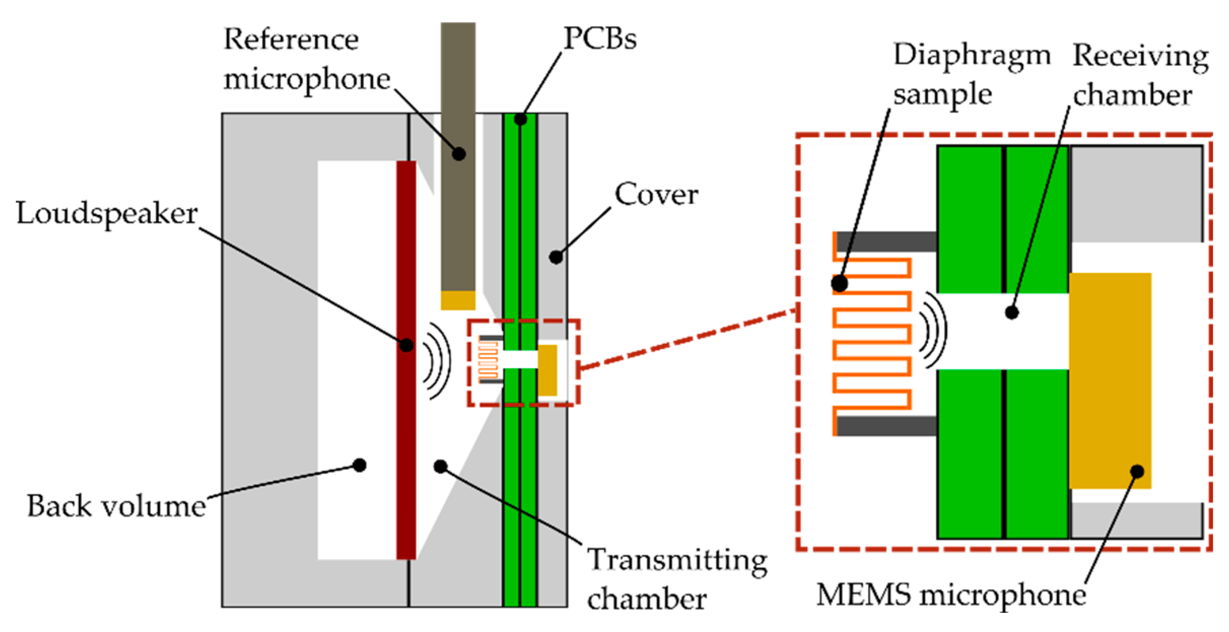
Figure 2.
Schematic illustration of (a) the measurement setup without a folded diaphragm; (b) its measured acoustic damping behavior.
Figure 2.
Schematic illustration of (a) the measurement setup without a folded diaphragm; (b) its measured acoustic damping behavior.
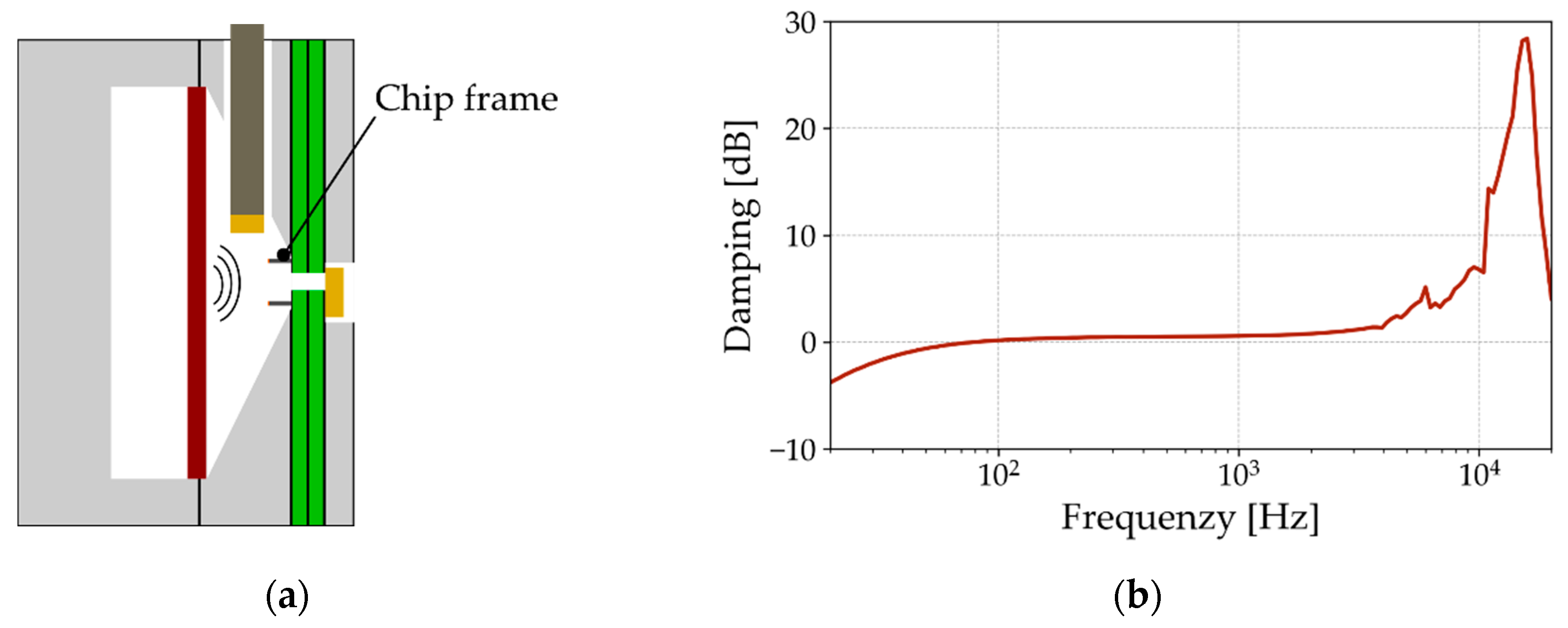
Figure 3.
SEM micrograph of a cross-section polished folded diaphragm.
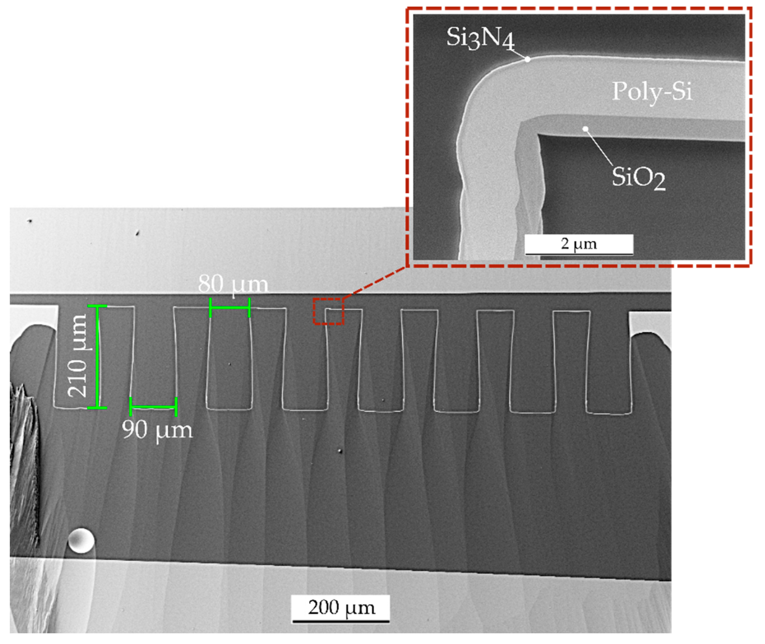
Figure 4.
Results from the acoustic measurements showing (a) the measured SPL in both chambers for three 2000 µm long diaphragms; (b) the determination of their damping characteristics.
Figure 4.
Results from the acoustic measurements showing (a) the measured SPL in both chambers for three 2000 µm long diaphragms; (b) the determination of their damping characteristics.
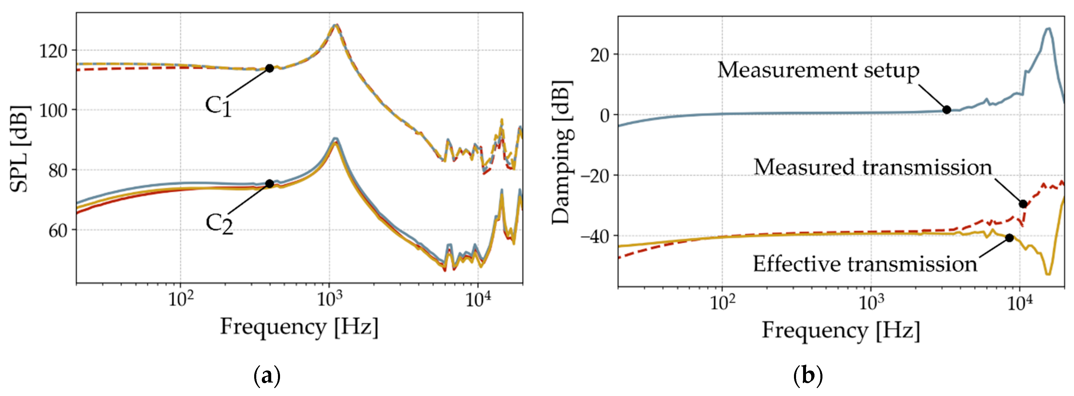
Figure 5.
Radiated SPL at 1 kHz through the folded diaphragm for different input pressures.
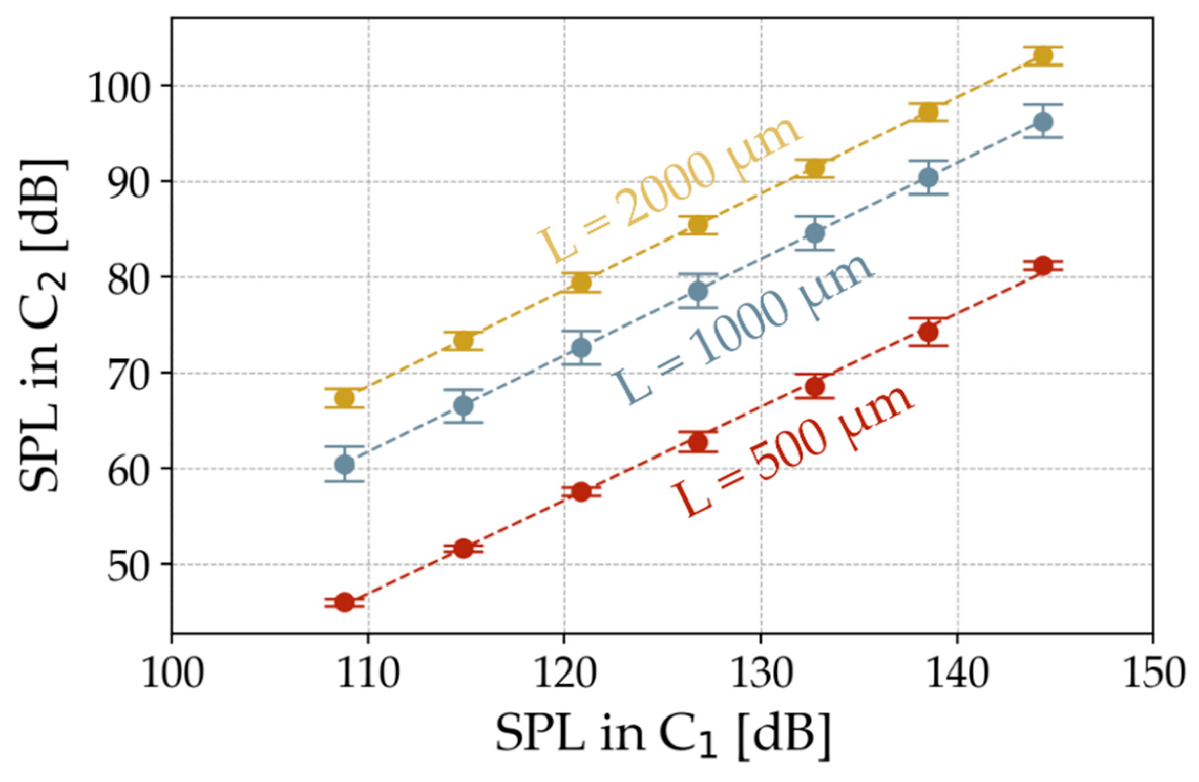
Figure 6.
Illustration of (a) the Lumped-element model of the measurement setup; (b) the resulting compliance extraction for 2000 µm long diaphragms.
Figure 6.
Illustration of (a) the Lumped-element model of the measurement setup; (b) the resulting compliance extraction for 2000 µm long diaphragms.
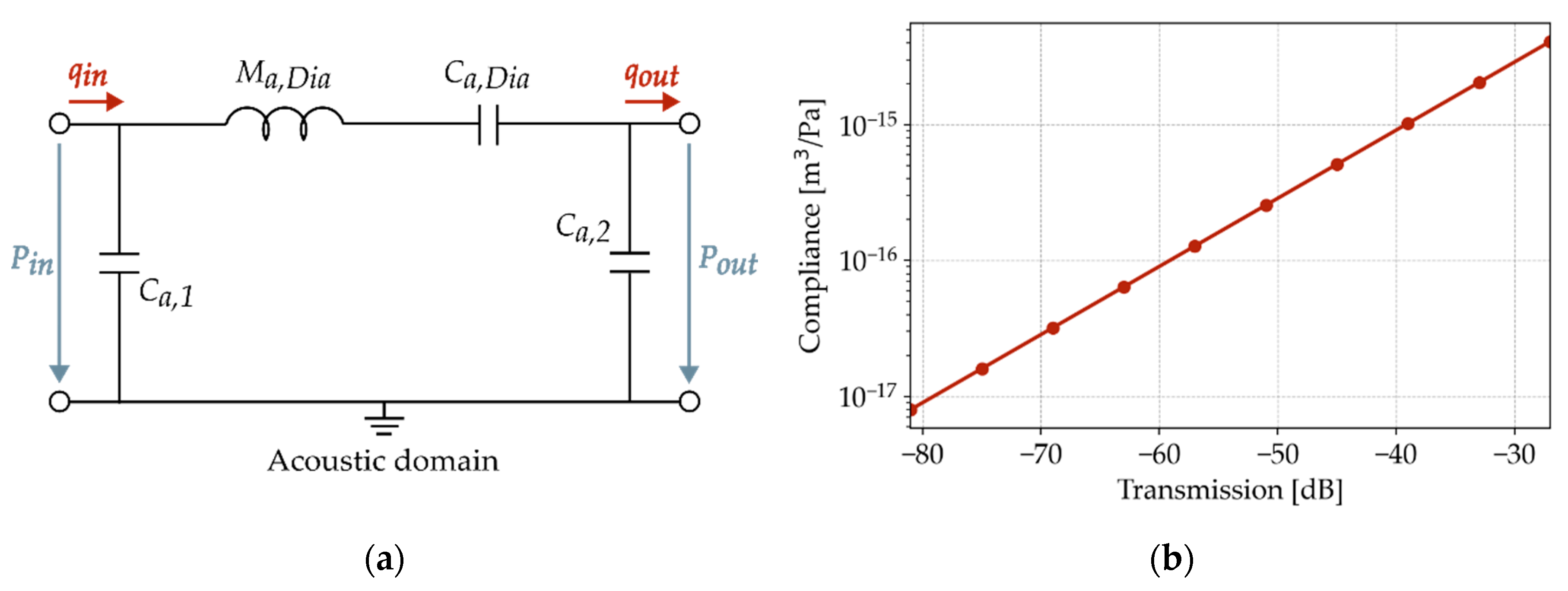
Figure 7.
Numerical simulation of the deflected folded diaphragm with an input pressure Pin.
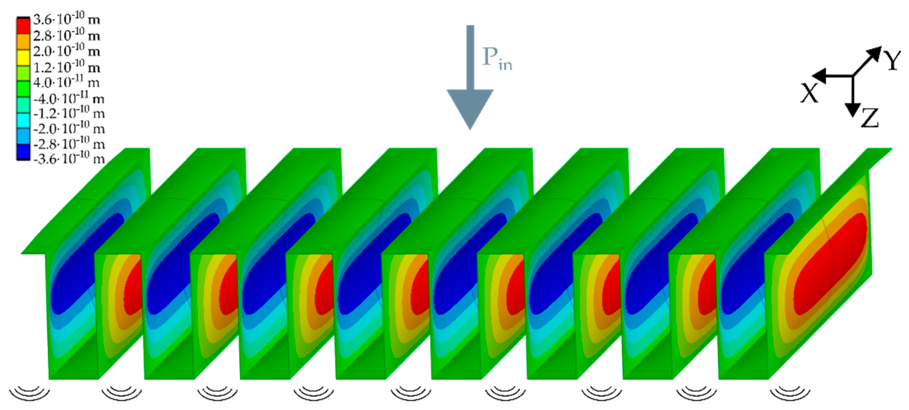
Figure 8.
Comparison of extracted acousitc compliances from transmission measurements, numerical simulations and theory.
Figure 8.
Comparison of extracted acousitc compliances from transmission measurements, numerical simulations and theory.
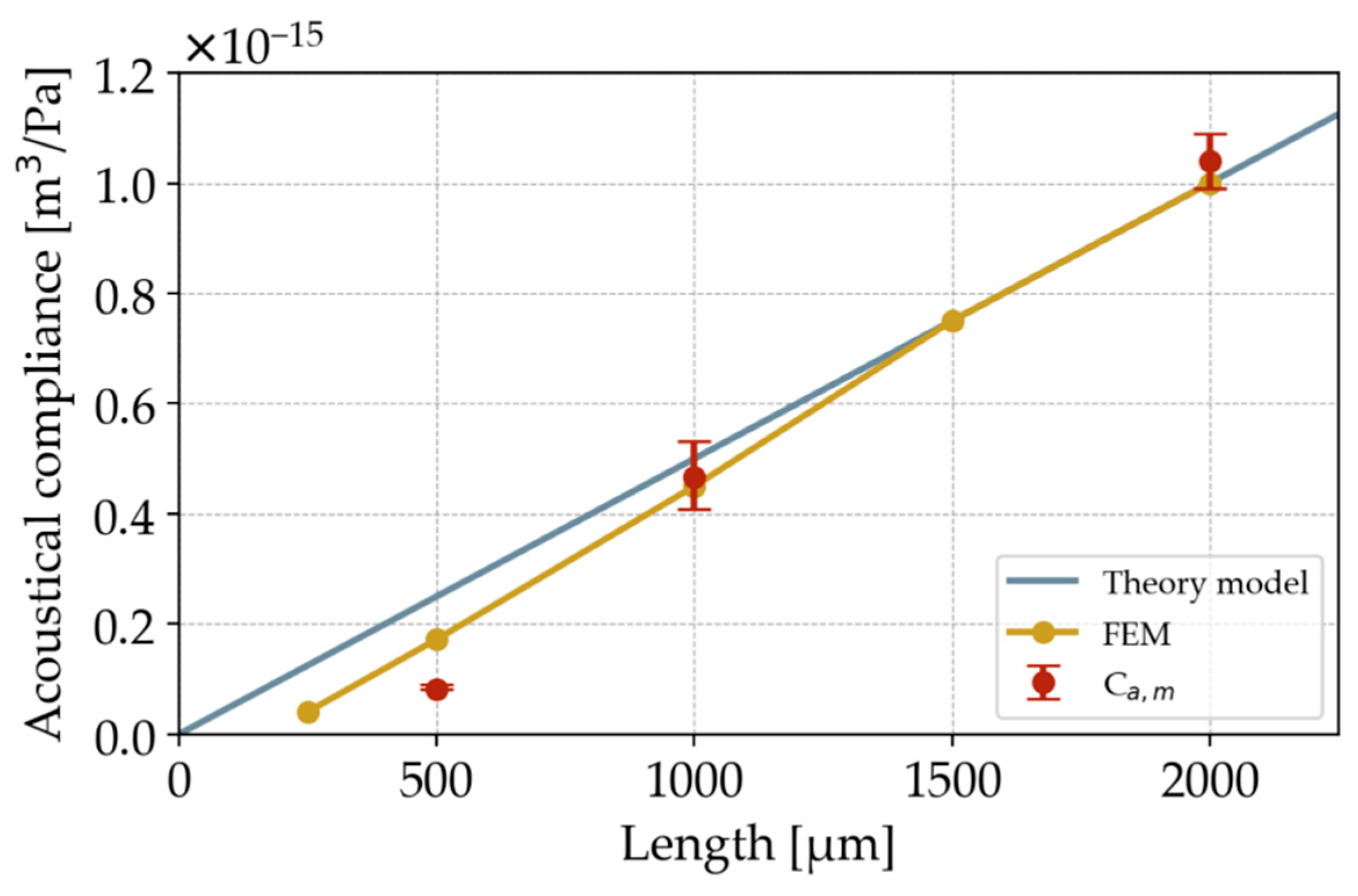

Table 1.
Material properties of the diaphragm layer stack.
| Thin film material | Thickness [nm] | Density [kg/m³] |
|---|---|---|
| SiO2 | 400 | 2180 [14] |
| Poly-Si | 1000 | 2300 [15] |
| Si3N4 | 110 | 3187 [16] |
Table 2.
Comparison of determined acoustic compliances to state of the art transducer diaphragms.
| Transducer | Acoustic compliance [m3/Pa] | Transducer area [mm2] |
|---|---|---|
| Folded diaphragm (2000 µm) | 400 | 2.4 |
| Folded diaphragm (1000 µm) | 1000 | 1.2 |
| Folded diaphragm (500 µm) | 110 | 0.6 |
| [17] | 0.026 ∙ 10-15 | 2.25 |
| [18]1 | 14.4 ∙ 10-15 | 1.44 |
| [19]1 | 34.75 ∙ 10-15 | 20.25 |
| [20]1 | 1.4 ∙ 10-15 | 0.57 |
1 Calculated from given mechanical compliance values.
Disclaimer/Publisher’s Note: The statements, opinions and data contained in all publications are solely those of the individual author(s) and contributor(s) and not of MDPI and/or the editor(s). MDPI and/or the editor(s) disclaim responsibility for any injury to people or property resulting from any ideas, methods, instructions or products referred to in the content. |
© 2024 by the authors. Licensee MDPI, Basel, Switzerland. This article is an open access article distributed under the terms and conditions of the Creative Commons Attribution (CC BY) license (http://creativecommons.org/licenses/by/4.0/).
Copyright: This open access article is published under a Creative Commons CC BY 4.0 license, which permit the free download, distribution, and reuse, provided that the author and preprint are cited in any reuse.


