Preprint
Article

Green Scalar Function Method for Analyzing Dielectric Media

Altmetrics

Downloads

79

Views

35

Comments

0

A peer-reviewed article of this preprint also exists.

Submitted:

02 August 2024

Posted:

02 August 2024

You are already at the latest version

Alerts
Abstract
In this work we present a formalism based on scalar Green’s functions to deal with electromagnetic scattering problems. Although the formulations of the Mie theory and Born approximations in terms of electromagnetic scattering are well known and relevant, they have certain disadvantages; complexity, computational time, few symmetries, etc. Therefore, the study with scalar Green’s functions allows dealing with these problems with greater simplicity and efficiency. However, the information provided by the vector formulation is sacrificed. Nevertheless, different cases of electromagnetic scattering of dielectric media with different dimensions, geometries and refractive indices will be presented. Thus, we will be able to verify the capacity of this scalar method in predicting light scattering problems.
Keywords: 
Subject: Physical Sciences  -   Optics and Photonics

1. Introduction

Scattering problems are of great importance in applications such as optical device design [1], medical imaging [2], object detection and materials science. Theories such as the Mie theory [3], the Born approximation [4] and advanced numerical methods are essential tools for tackling these problems [5,6,7]. Some of these methods consists on solving time-dependent Maxwell’s equations [8], obtaining Mie’s coefficients [9], employing method of moments (MoM) or Galerkin Method [10] . However, these theories have certain disadvantages such as: complex and computationally expensive calculations, application to regular surfaces, lack of accuracy with high dielectric constant or small dimensions, hard dicretization of the equations, etc. [11,12]. Therefore, in the present work a scalar formalism with Green’s functions [13,14] is shown. These show the impulsional response of a linear system. Specifically, in the electromagnetic domain, an impulsional response represents a point source in space as if it were a Dirac delta. This makes it possible to describe the electric and magnetic fields and their potentials in terms of these point sources. This allows us to know the distribution of the reflected, refracted and scattered fields. On the other hand, the scalar formulation allows us greater computational efficiency and the possibility of contrasting this methodology with different scattering cases where an analytical solution is presented. To this end, the Helmholtz equation will be derived from Maxwell’s equations and the solution of this equation will be posed in terms of the scalar Green’s functions. In some cases, due to the symmetry of the problem, the dimensionality can be simplified. In the following, different geometries will be presented in order to analyse the resulting electromagnetic scattering, varying the system’s own parameters such as dimensions and refractive index.

2. Theoretical Background

The Green’s function applied to the Helmholtz equation is the solution of the wave equation for a point source. Thus if the solution for this point source is known, then the solution for a general source can be obtained by the superposition principle. This result follows from the linearity of the wave equation itself, since any source can be described by the linear superposition of point sources [15]. For our case we will consider a scalar field E ( r ) which has a source s ( r ) . The Helmholtz equation associated with this system would be
( 2 + k 2 ) E ( r ) = s ( r )
And using the definition of Green’s scalar function, now renamed g ( r , r ) we have that
2 + k 2 g ( r , r ) = δ ( r r )
Thus, we can establish a relationship between (1) and (2) as
E ( r ) = V g ( r , r ) s ( r ) d r
The solution of the scalar Green’s function in 3D is obtained in Appendix A. This solution will only depend on R = | r r | and in general could be written as
g 3 D ( r , r ) = g ( r r ) = e i k | r r | 4 π | r r | = e i k R 4 π R
Given the equations (3) and (4), we can write the scalar field associated with such a source as
E ( r ) = V e i k | r r | 4 π | r r | s ( r ) d r

2.1. 2D Green Function

As in 3D systems, the scalar Green’s function in 2D geometries will only depend on the relative position between the source and the observer, so it is convenient to define the relative coordinates.
r r ρ ρ = ρ cos ϕ , ρ sin ϕ , 0 = ( x x , y y , z z )
Thus, reducing the three-dimensional problem to one in the plane. In the 3D case the scalar Green’s function refers to a point source of electromagnetic fields, located in ( x , y , z ) = ( 0 , 0 , z ) . However, the 2D case refers to the field generated by an infinite linear charge source observed in a plane z = cte whose axial dependence for with the term exp ( i k z z ) . So, one can obtain this 2D Green’s function, g 2 D ( r , r ) as the line integral of this linear source
g 2 D ( r , r ) = g 3 D ( r , r ) e i k z z d z = e i k x 2 + y 2 + ( z z ) 2 4 π x 2 + y 2 + ( z z ) 2 e i k z z d z = i 4 H 0 ( k ρ ρ ) e i k z z
where H 0 ( k ρ ρ ) denotes the Hankel function of first kind and k = | k | = | ( k ρ , k z ) | is the wave vector modulus and k ρ = | k ρ | is the transverse wave vector modulus, respectively.

2.2. Discretization of the Equations

Consider the Helmholtz scalar equation applied to the electric field and applied to a Green scalar function
2 E ( r ) + k 0 2 ε B E ( r ) = k 0 2 Δ ε ( r ) E ( r )
2 + k 0 2 ε B g ( r , r ) = δ ( r , r )
Where, Δ ε ( r ) = ε ( r ) ε B is the dielectric contrast, indicating the difference in dielectric permittivity between the object ε ( r ) and the background ε B . The procedure followed to obtain the scattered pattern is analogous to the one described in [16], except that we address the scalar case. On the other hand, if we introduce equation (9) into equation (8), electric field E ( r ) can be obtained by
E ( r ) = E ( 1 ) ( r ) + V g ( r , r ) · k 0 2 Δ ε ( r ) E ( r ) d r
Where the integration is calculated over the whole volume of the chosen simulated region and E ( 1 ) ( r ) refers to the incident electric field. The circumstance to be solved that may arise in the study of a reduced volume is the singularity | r r | 0 . Therefore, when r r , the singularity can be avoided if we exclude that inifinitesimal element of volume δ V where this singularity is found. We can then treat this singularity separately, rewriting the equation (10) as
E ( r ) = E ( 1 ) ( r ) + lim δ V 0 V δ V g ( r , r ) · k 0 2 Δ ε ( r ) E ( r ) d r L · Δ ε ( r ) ε B E ( r )
Where L is a scalar term derived from the dyad L [16] which depends on the geometry of the excluded volume δ V . Thus, in our work the observation point r is located outside the dispersive medium or “scatterer‘’, whose position is given by r . To solve equation (11) numerically, we must first define a grating of N nodes which represents the system. Each node i will be centred in a position r i and will present a volume V i if we are in 3D or an area in 2D and a value of dielectric contrast. Following, electric field E i = E ( r i ) must be discretized as well as scalar Green’s function g i , j = g ( r i , r j ) .
E i = E i ( 1 ) + j = 1 j i N g i , j · k 0 2 Δ ε j E j V j + M i · k 0 2 Δ ε i E i L · Δ ε i ε B E i i = 1 , , N
and
M i = lim δ V 0 V i δ V g ( r i , r ) d r
Throughout the implementation of the codes and simulations it has become clear that the terms where the scalar Green’s function or the geometric factor L appears, these prevail over M i . However, many authors for more complex geometries than the ones we will deal with in the project show that the M i term is more relevant than the L term E i as in [16]. The equations (12) represent a linear system of equations that can be solved with simple numerical methods. Expressing the system of equations in the form
E i ( 1 ) = E i · 1 M i k 0 2 Δ ε i + L Δ ε i ε B j = 1 j i N g i , j · k 0 2 Δ ε j E j V j E j E i = A G 1 E i ( 1 )
where A G is the interaction matrix which contains the scalar Green’s function and the dielectric contrast and geometric factor terms of the source L, defined by:
A G ( i , j ) = 1 M i k 0 2 Δ ε i + L Δ ε i ε B if i = j g i , j k 0 2 Δ ε j V j if i j
Following our notation; E i is the simulated electric field matrix, and E i ( 1 ) is the incident field.

2.3. Scalar Analytical Solution

The scalar approximation simplifies the analysis of electromagnetic wave scattering by reducing the problem to a scalar field, rather than dealing with the full vector nature of electromagnetic fields. This approach is especially useful when the variations in the wave field occur mainly in a single component, allowing for simpler mathematical handling and greater computational efficiency. By using scalar fields, we can take advantage of well-established mathematical techniques, such as Fourier series, to express the fields in terms of their angular harmonics. In order to compare the numerical results, analytical solution present in [17] are used. In order to achieve this, an homogeneous cylinder is considered to obtain the scattered field in cylindrical coordinates in terms of a Fourier series in the angular coordinate. Lets us consider an incident wave front in plane y = 0 parallel polarized respect z-axis, thus the electric field in cylindrical coordinates expressed as a Fourier series in the angular coordinate is given by:
E ( 1 ) ( ρ , ϕ ) = E 0 e i k x = E 0 m = i m J m ( k ρ ) e i m ϕ
where E 0 is the amplitude of the incident wave, ϕ is the angle that the scattered wave forms with respect to the incident wave and J is the Bessel function of first kind. Once we have expressed the incident field in Fourier terms as a function of the angular harmonics, we can give the expression for the scattered field as
E ( 3 ) ( ρ , ϕ ) = E 0 e i k ρ cos ϕ = E 0 m = i m α m H m ( k ρ ) e i m ϕ
This Equation (17) satisfies the Sommerfeld radiation condition at infinity. Where α m is a constant describing the continuity of the dielectric field derived by the boundary conditions as is is obtained in [18] for a perpendicular polarization across the x z -plane, is given by
α m = n J m ( k a ) J m ( n k a ) J m ( k a ) J m ( n k a ) n J m ( n k a ) H m ( k a ) J m ( k n a ) H m ( k a )
where k = 2 π / λ is the modulus of grating vector k , n is the refractive index of the dielectric media and a is the cylinder radius. The scalar approximation provides significant insight into the scattering problem by simplifying the analysis. However, it should be noted that the solutions obtained using this scalar approximation are analogous to those derived from the full vector treatment in the case of TE (Transverse Electric) polarisation. In this context, TE polarisation implies that the electric field is perpendicular to the plane of incidence, making the scalar approximation of the field a valid representation of the vector field under these specific conditions. As described by [16].

3. Numerical Results

First, analytical solution obtained by the Fourier series development of the angular harmonics are compared with the scalar formalism of the Green’s function. In order to achieve this, consider the following coordinate scheme presented in Figure 1. Where a plane wave polarized perpendicular impinges on the cylinder in the x z -plane with a tilt angle ζ , and the intensity pattern of the scattered light is measured on a screen. On the other hand, the screen where the intensity pattern is collected can be moved along the axial axis y and the intensity can be gathered at different distances from the cylinder.
In the following simulations we can see the axial evolution of the normalized intensity of the scattered light in Figure 2a, moving towards the screen respect the cylinder, and the pattern of the scattered light on the screen at a distance of y = 10 mm , Figure 2b. We can see that the proposed numerical method with the Green’s function approximates and behaves in an analogous way to the analytical solution proposed by the Equation (17). Moreover, in Figure 2a we observe that for values close to y = 0 the behaviour of the axial intensity curve presents some abrupt changes in the intensity, which is in agreement with the scalar theory of diffraction being in the Fresnel regime close to the source.
Modifying the dimensions of the dielectric medium, in this case reducing its dimensions by half ( a = 20 μ m ), we can observe how the pattern of the scattered beam on the screen widens with respect to the intensity pattern for a cylinder twice the size, Figure 3b respect Figure 2b. This result shows that the light scattered by the dielectric medium actually has its origin in the diffraction that the cylinder itself performs when incident on light. On the other hand, the axial behaviour of the intensity, Figure 3a of the scattered beam shows less variation as it approaches the source and decays faster than for a larger scattering medium in comparison with Figure 2a. These two comments are consistent with the scalar theory of light diffraction. On the other hand, the solution obtained by the scalar Green’s method fits better to the analytical solution (17).
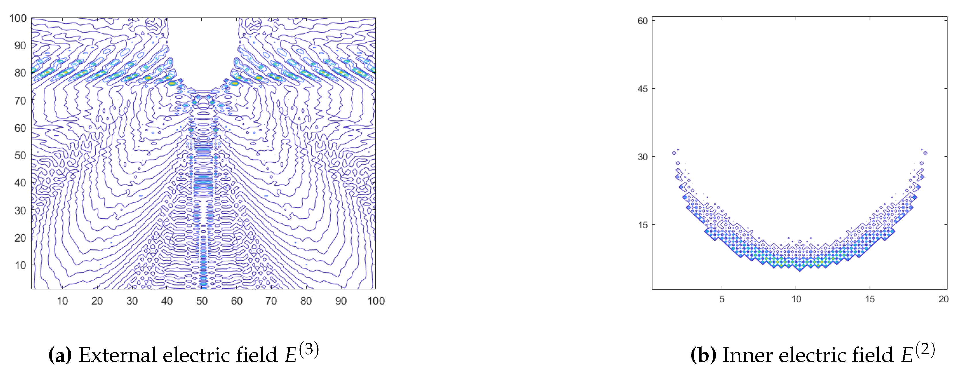
Once it has been demonstrated that the numerical method fits the analytical prediction, we decided to try different geometries and to analyze the scattered field in the plane. Thus, the following results represent the light scattering of different dielectric surfaces. For this purpose, 2D scalar Green’s function given by the Equation (9) is used. In Figure 4a we consider a cylinder with an elliptical base with a semi-major axis a = 30 μ m and semi-minor axis b = 10 μ m with refractive index n = 1.5 . A planar wave front with a wavelength of λ = 633 nm propagating in air impinges normally on the surface, ζ = π / 2 . We can observe the pattern of the scattered field E ( 3 ) once the electromagnetic wave interacts with the dielectric cylinder. This presents two clear scattered wave fronts which refers to the reflection of the incident wave E ( 1 ) . On the other hand, in Figure 4b the intensity of the refracted field inside the dielectric cylinder is represented.
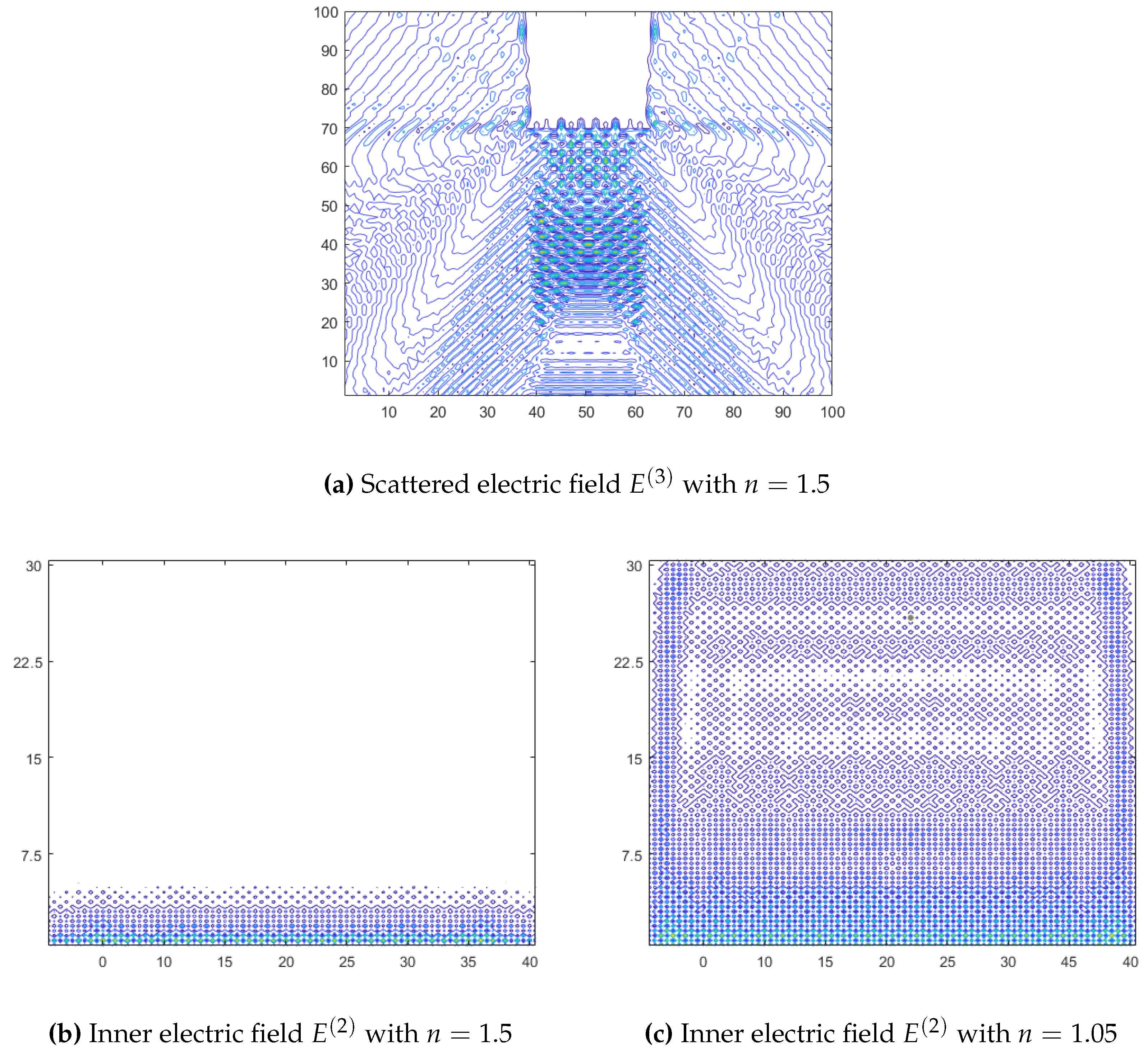
Trying other geometries we opted for a prism with a rectangular base 20 × 30 μ m 2 . We have in the following Figure 5a the scattered field by this new dielectric medium for a refractive index n = 1.5 and the internal field for different refractive indices, n = 1.5 in Figure 5b and n = 1.05 in Figure 5c. We can observe how the homogeneity of the transmitted electromagnetic wave has a certain dependence on the difference between refractive indices of the dielectric medium with respect to the external medium, in this case air n = 1 . These results make sense because the intensity of the field transmitted by the dielectric medium depends on the refractive index due to the Fresnel equations, so the greater the relative difference in refractive indices, the less electric field will be transmitted and the less scattered field at the output of the dielectric medium. Furthermore, we can see how the areas of highest intensity are at the interface between refracting surfaces, and this intensity decreases as the electric field propagates through the interior of the prism as it occurs in the dielectric cylinder. Good agreement between scalar Green method and vector form [19,20] is observed.

4. Conclusions

The simplicity of the equations derived from the Green’s functions combined with the proposed numerical method makes this approximate method a good approach to deal with electromagnetic scattering problems. Moreover, this numerical method has been compared with other analytical solutions proposed in the literature and it has been found to fit properly. In addition, phenomena such as light diffraction have been verified by modifying the dimensions of the selected dielectric element, in this work a homogeneous cylinder. Another aspect shown is the transmission of light through a dielectric medium. To sum up, we can say that Green’s method makes it possible to recreate the phenomena of both diffraction and refraction of light. However, as it is a scalar method, information about the degree of polarization of the scattered wave is missed. Thus, this aspect that could be carried out with a vectorial numerical method based on a tensor formalism with Green’s functions.

Author Contributions

Following the taxonomy of CRediT, the contributions of each author are as follows: J. C. Bravo contributed to the conceptualization, formal analysis, investigation, methodology, resources, software development, data curation, visualization, and writing of the original draft as well as the review and editing of the manuscript. J. Colomina-Martínez managed to the formal analysis, investigation, software development and data curation. J. J. Sirvent-Verdú colaborated on formal analysis, investigation, software development and data curation. E. J. Mena assisted in investigation and visualization. M. L. Álvarez took part in formal analysis, investigation and visualization. J. Francés supported in resources, software development, data curation and visualization. C. Neipp was involved in project administration, conceptualization, investigation, resources, software development, supervision, validation, and visualization. S. Gallego was responsible for funding acquisition, project administration, conceptualization, investigation, methodology, resources, supervision, validation, and visualization.

Funding

Funded by the “Generalitat Valenciana” (Spain) (IDIFEDER/2021/014, cofunded by EU through FEDER Programme; PROMETEO/2021/006 and INVEST/2022/419 financed by Next Generation EU), “Ministerio de Ciencia e Innovación” (Spain) (PID2021-123124OB-I00 and PID2019-106601RB-I00).

Conflicts of Interest

The authors declare that they have no known competing financial interests or personal relationships that could have appeared to influence the work reported in this paper.

Appendix A. Obtaining Green’s Scalar Function

If we use the definition of Green’s scalar function, now renamed g ( r , r ) we have that
2 + k 2 g ( r , r ) = δ ( r r )
Given g ( r , r ) we can find E ( r ) by the superposition principle, since the function g is a solution of the Equation (1). To do this, we can define the arbitrary source s ( r ) as
s ( r ) = s ( r ) δ ( r r ) d r
This shows the superposition of point sources. Consistent with this result, the solution of (1) turns out to be
E ( r ) = V g ( r , r ) s ( r ) d r
Being V the volume of our system to be studied. If we now consider a sufficiently large homogeneous medium, we can solve it if spherical coordinates are considered with the origin at r . Thus, the Equation (A1) would be as follows
2 + k 2 g ( r ) = δ ( r )
That by spherical symmetry, g ( r ) must also preserve it. So, for r 0 , we can replace the vector r by the scalar r and give a spherically symmetric homogeneous solution, such as
g ( r ) = c 1 e i k r r + c 2 e i k r r c 1 , c 2 R
Considering now that we have no sources at infinity, the previous equation can be simplified into
g ( r ) = c e i k r r
Therefore, we are left with the only salient solution. In order to find this constant c we are going to consider a small volume of our system δ V and we are going to integrate the Equation (A1) in it.
δ V 2 c e i k r r d V + δ V k 2 c e i k r r d V = 1
We can appreciate that the second integral cancels out, since if we take a sufficiently small volume r 0 , this integral will be proportional to r, since d V = r 2 d r d θ d ϕ . Taking the limit when r 0 we would have that by the divergence theorem
lim r 0 δ V · c e i k r r d V = lim r 0 δ A c e i k r r d A = = lim r 0 4 π r 2 c d d r e i k r r = 1 c = 1 4 π
Thus, the solution of the scalar Green’s function will only depend on r r and in general as
g ( r , r ) = g ( r r ) = e i k | r r | 4 π | r r | = e i k R 4 π R
Given the Equations (A3) and (A9), we can write the scalar field associated with such a source as
E ( r ) = V e i k | r r | 4 π | r r | s ( r ) d r

References

  1. Stefanou, N.; Karathanos, V.; Modinos, A. Scattering of electromagnetic waves by periodic structures. Journal of Physics: Condensed Matter 1992, 4, 7389. [Google Scholar] [CrossRef]
  2. Rekanos, I.T. Neural-network-based inverse-scattering technique for online microwave medical imaging. IEEE transactions on magnetics 2002, 38, 1061–1064. [Google Scholar] [CrossRef]
  3. Nieto-Vesperinas, M. Fundamentals of Mie scattering. In Dielectric Metamaterials; Elsevier, 2020; pp. 39–72.
  4. Habashy, T.M.; Groom, R.W.; Spies, B.R. Beyond the Born and Rytov approximations: A nonlinear approach to electromagnetic scattering. Journal of Geophysical Research: Solid Earth 1993, 98, 1759–1775. [Google Scholar] [CrossRef]
  5. Rao, S.; Wilton, D.; Glisson, A. Electromagnetic scattering by surfaces of arbitrary shape. IEEE Transactions on antennas and propagation 1982, 30, 409–418. [Google Scholar] [CrossRef]
  6. Rother, T. Self-consistent Green’s function formalism for acoustic and light scattering, Part 1: Scalar notation. Optics communications 2005, 251, 254–269. [Google Scholar] [CrossRef]
  7. Ishimaru, A. Electromagnetic wave propagation, radiation, and scattering: from fundamentals to applications; John Wiley & Sons, 2017.
  8. Taflove, A.; Brodwin, M.E. Numerical solution of steady-state electromagnetic scattering problems using the time-dependent Maxwell’s equations. IEEE transactions on microwave theory and techniques 1975, 23, 623–630. [Google Scholar] [CrossRef]
  9. Shah, G.A. Numerical methods for Mie theory of scattering by a sphere 1977.
  10. Alyones, S.; Bruce, C.W.; Buin, A.K. Numerical methods for solving the problem of electromagnetic scattering by a thin finite conducting wire. IEEE Transactions on Antennas and propagation 2007, 55, 1856–1861. [Google Scholar] [CrossRef]
  11. Glisson, A.; Wilton, D. Simple and efficient numerical methods for problems of electromagnetic radiation and scattering from surfaces. IEEE Transactions on Antennas and Propagation 1980, 28, 593–603. [Google Scholar] [CrossRef]
  12. Sevgi, L. Complex electromagnetic problems and numerical simulation approaches; John Wiley & Sons, 2003.
  13. Huang, J.; Yao, J.; Xu, D.; Li, R. Green function method for the time domain simulation of pulse propagation. Appl. Opt. 2014, 53, 3533–3539. [Google Scholar] [CrossRef] [PubMed]
  14. Huang, J. Green Function. In Perturbation Theory; Uzunov, D.I., Ed.; IntechOpen: Rijeka, 2017; chapter3. [Google Scholar] [CrossRef]
  15. Wubs, M.; Suttorp, L.; Lagendijk, A. Multiple-scattering approach to interatomic interactions and superradiance in inhomogeneous dielectrics. Physical Review A—Atomic, Molecular, and Optical Physics 2004, 70, 053823. [Google Scholar] [CrossRef]
  16. Martin, O.J.; Piller, N.B. Electromagnetic scattering in polarizable backgrounds. Physical Review E 1998, 58, 3909–3915. [Google Scholar] [CrossRef]
  17. Petropoulos, P.G. Reflectionless sponge layers as absorbing boundary conditions for the numerical solution of Maxwell equations in rectangular, cylindrical, and spherical coordinates. SIAM Journal on Applied Mathematics 2000, 60, 1037–1058. [Google Scholar] [CrossRef]
  18. Frezza, F.; Mangini, F.; Tedeschi, N. Introduction to electromagnetic scattering: tutorial. JOSA A 2018, 35, 163–173. [Google Scholar] [CrossRef] [PubMed]
  19. Taleb, S.I.; Neipp, C.; Francés, J.; Martínez Guardiola, F.J.; Alvarez, M.L.; Márquez, A.; Gallego, S.; Beléndez, A.; others. 2D Green’s tensor for the analysis of dielectric structures with translational geometries. OPAL proceedings 2021. [Google Scholar]
  20. Yaghjian, A.D. Electric dyadic Green’s functions in the source region. Proceedings of the IEEE 1980, 68, 248–263. [Google Scholar] [CrossRef]
  21. Doicu, A.; Wriedt, T.; Eremin, Y.A. Light scattering by systems of particles: null-field method with discrete sources: theory and programs; Vol. 124, Springer, 2006.
  22. Kahnert, F.M. Numerical methods in electromagnetic scattering theory. Journal of Quantitative Spectroscopy and Radiative Transfer 2003, 79, 775–824. [Google Scholar] [CrossRef]
  23. Levine, H.; Schwinger, J. On the theory of electromagnetic wave diffraction by an aperture in an infinite plane conducting screen. Communications on Pure and Applied Mathematics 1950, 3, 355–391. [Google Scholar] [CrossRef]
  24. Bohren, C.F.; Huffman, D.R. Absorption and scattering of light by small particles; John Wiley & Sons, 2008.
  25. Paknys, R. Applied frequency-domain electromagnetics; John Wiley & Sons, 2016.
  26. Taleb, S.I.; Neipp, C.; Francés, J.; Márquez, A.; Alvarez, M.L.; Hernández, A.; Gallego, S.; Beléndez, A. Validation of Fresnel–Kirchhoff Integral Method for the Study of Volume Dielectric Bodies. Applied Sciences 2021, 11, 3800. [Google Scholar] [CrossRef]
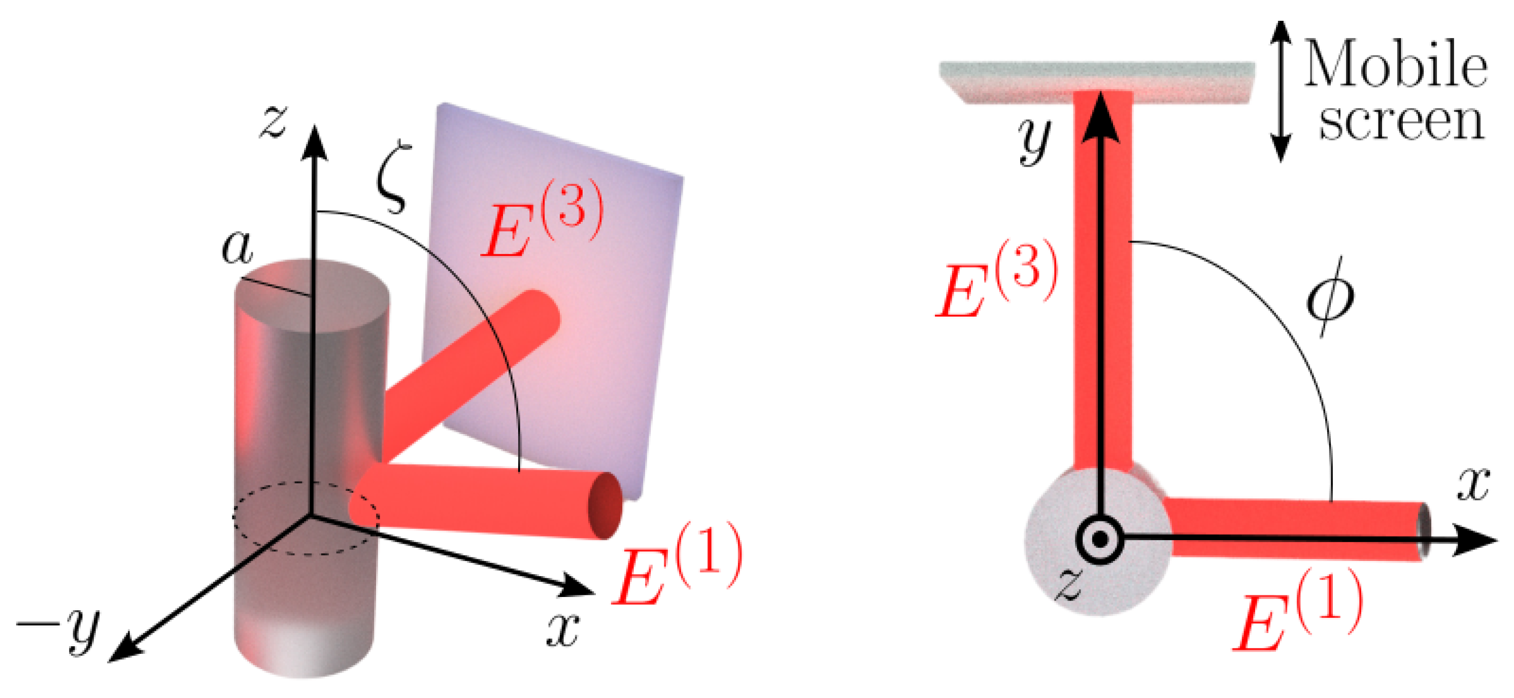
Figure 1. Coordinate system for a scattering cylinder
Preprints 114151 g001
Figure 2. Cylinder with circular base a = 40 μ m and with refractive index of n = 1.5 .
Preprints 114151 g002
Figure 3. Cylinder with circular base a = 20 μ m and with refractive index of n = 1.5 .
Preprints 114151 g003
Figure 4. Cylinder with elliptical base ( a = 30 μ m and b = 10 μ m ) with refractive index of n = 1.5 .
Preprints 114151 g004
Figure 5. Rectangular prism with base a = 20 μ m , b = 30 μ m and different refractive index.
Preprints 114151 g005
Disclaimer/Publisher’s Note: The statements, opinions and data contained in all publications are solely those of the individual author(s) and contributor(s) and not of MDPI and/or the editor(s). MDPI and/or the editor(s) disclaim responsibility for any injury to people or property resulting from any ideas, methods, instructions or products referred to in the content.
Copyright: This open access article is published under a Creative Commons CC BY 4.0 license, which permit the free download, distribution, and reuse, provided that the author and preprint are cited in any reuse.
Prerpints.org logo

Preprints.org is a free preprint server supported by MDPI in Basel, Switzerland.

Subscribe

© 2024 MDPI (Basel, Switzerland) unless otherwise stated