Submitted:
02 August 2024
Posted:
06 August 2024
You are already at the latest version
Abstract
Keywords:
1. Introduction
2. Materials and Methods
3. Results and discussion

| Catalyst | Yield (mmol/gcat) | Yield (mmol/gact.ph.) | Yield (mol%) |
| CeO2_Meso | 0.941 | 0.941 | 2x10⁻³ |
| CeO2@SBA-15_SC | 0.097 | 0.971 | 2x10⁻⁴ |
| CeO2@SBA-15_TS | 0.066 | 0.662 | 1x10⁻⁴ |
4. Conclusions
Supplementary Materials
Author Contributions
Funding
Data Availability Statement
Acknowledgments
Conflicts of Interest
References
- Mikulčić, H.; Skov, I.R.; Dominković, D.F.; Alwi, S.R.W.; Manan, Z.A.; Tan, R.; Duić, N.; Mohamad, S.N.H.; Wang, X. Flexible Carbon Capture and Utilization technologies in future energy systems and the utilization pathways of captured CO2. Renew. Sustain. Energy Rev. 2019, 114, 109338. [Google Scholar] [CrossRef]
- Fu, L.; Ren, Z.; Si, W.; Ma, Q.; Huang, W.; Liao, K.; Huang, Z.; Wang, Y.; Li, J.; Xu, P. Research progress on CO2 capture and utilization technology. J. CO2 Util. 2022, 66. [Google Scholar] [CrossRef]
- Ghiat, I.; Al-Ansari, T. A review of carbon capture and utilisation as a CO2 abatement opportunity within the EWF nexus. J. CO2 Util. 2021, 45. [Google Scholar] [CrossRef]
- Álvarez, A.; Bansode, A.; Urakawa, A.; Bavykina, A.V.; Wezendonk, T.A.; Makkee, M.; Gascon, J.; Kapteijn, F. Challenges in the Greener Production of Formates/Formic Acid, Methanol, and DME by Heterogeneously Catalyzed CO2Hydrogenation Processes. Chem. Rev. 2017, 117, 9804–9838. [Google Scholar] [CrossRef] [PubMed]
- Wang, D.; Shi, F.; Wang, L. A Review of Catalysts for Synthesis of Dimethyl Carbonate. Catalysts 2024, 14, 259. [Google Scholar] [CrossRef]
- Zhang, M.; Xu, Y.; Williams, B.L.; Xiao, M.; Wang, S.; Han, D.; Sun, L.; Meng, Y. Catalytic materials for direct synthesis of dimethyl carbonate (DMC) from CO2. J. Clean. Prod. 2020, 279, 123344. [Google Scholar] [CrossRef]
- Ashok, J.; Pati, S.; Hongmanorom, P.; Tianxi, Z.; Junmei, C.; Kawi, S. A review of recent catalyst advances in CO2 methanation processes. Catal. Today 2020, 356, 471–489. [Google Scholar] [CrossRef]
- Atzori, L.; Cutrufello, M.G.; Meloni, D.; Secci, F.; Cannas, C.; Rombi, E. Soft-templated NiO–CeO2 mixed oxides for biogas upgrading by direct CO2 methanation. Int. J. Hydrogen Energy 2023, 48, 25031–25043. [Google Scholar] [CrossRef]
- Guil-López, R.; Mota, N.; Llorente, J.; Millán, E.; Pawelec, B.; Fierro, J.L.G.; Navarro, R.M. Methanol Synthesis from CO2: A Review of the Latest Developments in Heterogeneous Catalysis. Materials 2019, 12, 3902. [Google Scholar] [CrossRef] [PubMed]
- Catizzone, E.; Migliori, M.; Purita, A.; Giordano, G. Ferrierite vs. γ-Al2O3: The superiority of zeolites in terms of water-resistance in vapour-phase dehydration of methanol to dimethyl ether. J. Energy Chem. 2019, 30, 162–169. [Google Scholar] [CrossRef]
- Catizzone, E.; Freda, C.; Braccio, G.; Frusteri, F.; Bonura, G. Dimethyl ether as circular hydrogen carrier: Catalytic aspects of hydrogenation/dehydrogenation steps. J. Energy Chem. 2020, 58, 55–77. [Google Scholar] [CrossRef]
- Secci, F.; Mameli, V.; Rombi, E.; Lai, S.; Angotzi, M.S.; Russo, P.A.; Pinna, N.; Mureddu, M.; Cannas, C. On the role of the nature and density of acid sites on mesostructured aluminosilicates dehydration catalysts for dimethyl ether production from CO2. J. Environ. Chem. Eng. 2023, 11. [Google Scholar] [CrossRef]
- Cara, C.; Secci, F.; Lai, S.; Mameli, V.; Skrodczky, K.; Russo, P.A.; Ferrara, F.; Rombi, E.; Pinna, N.; Mureddu, M.; et al. On the design of mesostructured acidic catalysts for the one-pot dimethyl ether production from CO2. J. CO2 Util. 2022, 62. [Google Scholar] [CrossRef]
- Pyo, S.-H.; Park, J.H.; Chang, T.-S.; Hatti-Kaul, R. Dimethyl carbonate as a green chemical. Curr. Opin. Green Sustain. Chem. 2017, 5, 61–66. [Google Scholar] [CrossRef]
- Tan, H.-Z.; Wang, Z.-Q.; Xu, Z.-N.; Sun, J.; Xu, Y.-P.; Chen, Q.-S.; Chen, Y.; Guo, G.-C. Review on the synthesis of dimethyl carbonate. Catal. Today 2018, 316, 2–12. [Google Scholar] [CrossRef]
- Raza, A.; Ikram, M.; Guo, S.; Baiker, A.; Li, G. Green Synthesis of Dimethyl Carbonate from CO2 and Methanol: New Strategies and Industrial Perspective. Adv. Sustain. Syst. 2022, 6. [Google Scholar] [CrossRef]
- Yang, Z.; Zheng, J.T.; Lu, X.; Lin, M.M.; Cai, D.; Wang, Y.; Yu, W.-Y.; Zhu, Y.; Xia, Y. Porous ceria materials for efficient direct conversion of carbon dioxide and methanol to dimethyl carbonate. Mater. Adv. 2024. [Google Scholar] [CrossRef]
- Hou, G.; Wang, Q.; Xu, D.; Fan, H.; Liu, K.; Li, Y.; Gu, X.; Ding, M. Dimethyl Carbonate Synthesis from CO2 over CeO2 with Electron-Enriched Lattice Oxygen Species. Angew. Chem. Int. Ed. 2024, 63, e202402053. [Google Scholar] [CrossRef] [PubMed]
- Marciniak, A.A.; Alves, O.C.; Appel, L.G.; Mota, C.J. Synthesis of dimethyl carbonate from CO2 and methanol over CeO2: Role of copper as dopant and the use of methyl trichloroacetate as dehydrating agent. J. Catal. 2019, 371, 88–95. [Google Scholar] [CrossRef]
- Marciniak, A.A.; Santos, E.C.S.; Caraballo-Vivas, R.J.; Alves, O.C.; da Costa, M.E.H.M.; Garcia, F.; Mota, C.J.A. CeO2-Decorated α-Fe2O3 Nanorings for the Direct Synthesis of Dimethyl Carbonate from CO2 and Methanol. Energy Fuels 2023, 38, 628–636. [Google Scholar] [CrossRef]
- Seeharaj, P.; Saenman, T.; Phiwhom, T.; Muangsuwan, C.; Srinives, S.; Kim-Lohsoontorn, P. Improvement of surface properties of metal doped-CeO2 nanospindle catalysts for direct synthesis of dimethyl carbonate from CO2 and methanol. J. Environ. Chem. Eng. 2023, 11. [Google Scholar] [CrossRef]
- Kulthananat, T.; Kim-Lohsoontorn, P.; Seeharaj, P. Ultrasonically assisted surface modified CeO2 nanospindle catalysts for conversion of CO2 and methanol to DMC. Ultrason. Sonochemistry 2022, 90, 106164. [Google Scholar] [CrossRef] [PubMed]
- Dubey, M.; Wadhwa, S.; Mathur, A.; Kumar, R. Progress in mesoporous ceria: A review on synthesis strategies and catalytic applications. Appl. Surf. Sci. Adv. 2022, 12. [Google Scholar] [CrossRef]
- Sakina, F.; Muñoz-Ocaña, J.M.; Bouziane, A.; Lopez-Haro, M.; Baker, R.T. Synthesis of mesoporous ceria using metal- and halogen-free ordered mesoporous carbon as a hard template. Nanoscale Adv. 2019, 1, 4772–4782. [Google Scholar] [CrossRef] [PubMed]
- Roggenbuck, J.; Schäfer, H.; Tsoncheva, T.; Minchev, C.; Hanss, J.; Tiemann, M. Mesoporous CeO2: Synthesis by nanocasting, characterisation and catalytic properties. Microporous Mesoporous Mater. 2007, 101, 335–341. [Google Scholar] [CrossRef]
- Liang, X.; Xiao, J.; Chen, B.; Li, Y. Catalytically Stable and Active CeO2 Mesoporous Spheres. Inorg. Chem. 2010, 49, 8188–8190. [Google Scholar] [CrossRef] [PubMed]
- Wang, T.; Sel, O.; Djerdj, I.; Smarsly, B. Preparation of a large Mesoporous CeO2 with crystalline walls using PMMA colloidal crystal templates. Colloid Polym. Sci. 2006, 285, 1–9. [Google Scholar] [CrossRef]
- Junais, P.M.; Athika, M.; Govindaraj, G.; Elumalai, P. Supercapattery performances of nanostructured cerium oxide synthesized using polymer soft-template. J. Energy Storage 2020, 28, 101241. [Google Scholar] [CrossRef]
- Strunk, J.; Vining, W.C.; Bell, A.T. Synthesis of Different CeO2 Structures on Mesoporous Silica and Characterization of Their Reduction Properties. J. Phys. Chem. C 2011, 115, 4114–4126. [Google Scholar] [CrossRef]
- Dhall, A.; Self, W. Cerium Oxide Nanoparticles: A Brief Review of Their Synthesis Methods and Biomedical Applications. Antioxidants 2018, 7, 97. [Google Scholar] [CrossRef]
- Zagaynov, I.V.; Kutsev, S.V. Formation of mesoporous nanocrystalline ceria from cerium nitrate, acetate or acetylacetonate. Appl. Nanosci. 2013, 4, 339–345. [Google Scholar] [CrossRef]
- Borjas-García, S.E.; Medina-Flores, A.; Béjar, L.; Martínez-Torres, P.; Dasgupta-Schubert, N.; Bernal, J.L. Synthesis of Mesoporous Ceria by Using CTAB as Template. Microsc. Microanal. 2016, 22, 1918–1919. [Google Scholar] [CrossRef]
- Kurajica, S.; Minga, I.; Guliš, M.; Mandić, V.; Simčić, I. High Surface Area Ceria Nanoparticles via Hydrothermal Synthesis Experiment Design. J. Nanomater. 2016, 2016, 1–8. [Google Scholar] [CrossRef]
- Zhang, G.; Shen, Z.; Liu, M.; Guo, C.; Sun, P.; Yuan, Z.; Li, B.; Ding, D.; Chen, T. Synthesis and Characterization of Mesoporous Ceria with Hierarchical Nanoarchitecture Controlled by Amino Acids. J. Phys. Chem. B 2006, 110, 25782–25790. [Google Scholar] [CrossRef] [PubMed]
- Wang, M.-M.; He, L.; Liu, Y.-M.; Cao, Y.; He, H.-Y.; Fan, K.-N. Gold supported on mesostructured ceria as an efficient catalyst for the chemoselective hydrogenation of carbonyl compounds in neat water. Green Chem. 2011, 13, 602–607. [Google Scholar] [CrossRef]
- Liu, H.; Zhu, D.; Jia, B.; Huang, Y.; Cheng, Y.; Luo, X.; Liang, Z. Study on catalytic performance and kinetics of high efficiency CeO2 catalyst prepared by freeze drying for the synthesis of dimethyl carbonate from CO2 and methanol. Chem. Eng. Sci. 2022, 254. [Google Scholar] [CrossRef]
- Hu, L.; Hu, K.; Xu, Z.; Yao, W.; Wang, A.; Wu, G.; Xu, W. Preparation and Characterization of Hollow CeO2 Nanoparticles for the Efficient Conversion of CO2 into Dimethyl Carbonate. ChemCatChem 2023, 15. [Google Scholar] [CrossRef]
- Pouretedal, H.R.; Basati, S. Synthesis, Characterization and Photocatalytic Activity of CeO 2-SBA-15; 2012; Vol. 2;
- Mitran, R.-A.; Culita, D.C.; Atkinson, I. Thermal stability enhancement of mesoporous SBA-15 silica through nanoconfinement of ceria nanoparticles. Microporous Mesoporous Mater. 2020, 306, 110484. [Google Scholar] [CrossRef]
- Pu, Y.; Xuan, K.; Wang, F.; Li, A.; Zhao, N.; Xiao, F. Synthesis of dimethyl carbonate from CO2 and methanol over a hydrophobic Ce/SBA-15 catalyst. RSC Adv. 2018, 8, 27216–27226. [Google Scholar] [CrossRef]
- Shen, J.; Hess, C. Controlling the dispersion of ceria using nanoconfinement: application to CeO2/SBA-15 catalysts for NH3-SCR. Mater. Adv. 2021, 2, 7400–7412. [Google Scholar] [CrossRef]
- Yang, J.; Jia, Y.; Huang, B.; Li, X.; Guo, L.; Zheng, A.; Luque, R.; Sun, Y. Functionalized CeO2/SBA-15 Materials as Efficient Catalysts for Aqueous Room Temperature Mono-dehydration of Sugar Alcohols. ACS Sustain. Chem. Eng. 2020, 8, 6371–6380. [Google Scholar] [CrossRef]
- Saadati-Moshtaghin, H.R.; Zonoz, F.M. In situ preparation of CeO2 nanoparticles on the MCM-41 with magnetic core as a novel and efficient catalyst for the synthesis of substituted pyran derivatives. Inorg. Chem. Commun. 2018, 99, 44–51. [Google Scholar] [CrossRef]
- Ngomade, S.B.L.; Fotsop, C.G.; Nguena, K.L.T.; Tchummegne, I.K.; Ngueteu, M.L.T.; Tamo, A.K.; Nche, G.N.-A.; Anagho, S.G. Catalytic performances of CeO2@SBA-15 as nanostructured material for biodiesel production from Podocarpus falcatus oil. Chem. Eng. Res. Des. 2023, 194, 789–800. [Google Scholar] [CrossRef]
- Ma, K.; Zhang, H.; Tang, C.; Dong, L. One-Pot Synthesis of CeO2 Modified SBA-15 With No Pore Clogging for NO Reduction by CO. Front. Environ. Chem. 2021, 2. [Google Scholar] [CrossRef]
- Mureddu, M.; Ferino, I.; Musinu, A.; Ardu, A.; Rombi, E.; Cutrufello, M.G.; Deiana, P.; Fantauzzi, M.; Cannas, C. MeOx/SBA-15 (Me = Zn, Fe): highly efficient nanosorbents for mid-temperature H2S removal. J. Mater. Chem. A 2014, 2, 19396–19406. [Google Scholar] [CrossRef]
- Mureddu, M.; Ferino, I.; Rombi, E.; Cutrufello, M.; Deiana, P.; Ardu, A.; Musinu, A.; Piccaluga, G.; Cannas, C. ZnO/SBA-15 composites for mid-temperature removal of H2S: Synthesis, performance and regeneration studies. Fuel 2012, 102, 691–700. [Google Scholar] [CrossRef]
- Cara, C.; Rombi, E.; Mameli, V.; Ardu, A.; Angotzi, M.S.; Niznansky, D.; Musinu, A.; Cannas, C. γ-Fe2O3-M41S Sorbents for H2S Removal: Effect of Different Porous Structures and Silica Wall Thickness. J. Phys. Chem. C 2018, 122, 12231–12242. [Google Scholar] [CrossRef]
- Varma, A.; Mukasyan, A.S.; Rogachev, A.S.; Manukyan, K.V. Solution Combustion Synthesis of Nanoscale Materials. Chem. Rev. 2016, 116, 14493–14586. [Google Scholar] [CrossRef]
- Cannas, C.; Musinu, A.; Peddis, D.; Piccaluga, G. Synthesis and Characterization of CoFe2O4 Nanoparticles Dispersed in a Silica Matrix by a Sol−Gel Autocombustion Method. Chem. Mater. 2006, 18, 3835–3842. [Google Scholar] [CrossRef]
- Cannas, C.; Ardu, A.; Niznansky, D.; Peddis, D.; Piccaluga, G.; Musinu, A. Simple and fast preparation of pure maghemite nanopowders through sol–gel self-combustion. J. Sol-Gel Sci. Technol. 2011, 60, 266–274. [Google Scholar] [CrossRef]
- Cannas, C.; Musinu, A.; Peddis, D.; Piccaluga, G. New Synthesis of Ferrite–Silica Nanocomposites by a Sol–Gel Auto-Combustion. J. Nanoparticle Res. 2004, 6, 223–232. [Google Scholar] [CrossRef]
- Cannas, C.; Falqui, A.; Musinu, A.; Peddis, D.; Piccaluga, G. CoFe2O4 nanocrystalline powders prepared by citrate-gel methods: Synthesis, structure and magnetic properties. J. Nanoparticle Res. 2006, 8, 255–267. [Google Scholar] [CrossRef]
- Secci, F.; Angotzi, M.S.; Mameli, V.; Lai, S.; Russo, P.A.; Pinna, N.; Mureddu, M.; Rombi, E.; Cannas, C. Mesostructured γ-Al2O3-Based Bifunctional Catalysts for Direct Synthesis of Dimethyl Ether from CO2. Catalysts 2023, 13, 505. [Google Scholar] [CrossRef]
- Mureddu, M.; Ferrara, F.; Pettinau, A. Highly efficient CuO/ZnO/ZrO2@SBA-15 nanocatalysts for methanol synthesis from the catalytic hydrogenation of CO2. Appl. Catal. B: Environ. 2019, 258. [Google Scholar] [CrossRef]
- Zhao, D.; Wan, Y.; Zhou, W. Ordered Mesoporous Materials; Wiley-VCH, 2013; ISBN 9783527326358.
- Zhao, D.; Feng, J.; Huo, Q.; Melosh, N.; Fredrickson, G.H.; Chmelka, B.F.; Stucky, G.D. Triblock Copolymer Syntheses of Mesoporous Silica with Periodic 50 to 300 Angstrom Pores. Science 1998, 279, 548–552. [Google Scholar] [CrossRef] [PubMed]
- Le Bail, A. Modelling the silica glass structure by the Rietveld method. J. Non-Crystalline Solids 1995, 183, 39–42. [Google Scholar] [CrossRef]
- Ennas, G.; Marongiu, G.; Marras, S.; Piccaluga, G. Mechanochemical Route for the Synthesis of Cobalt Ferrite–Silica and Iron–Cobalt Alloy–Silica Nanocomposites. J. Nanoparticle Res. 2004, 6, 99–105. [Google Scholar] [CrossRef]
- Janssen, A.H.; Yang, C.-M.; Wang, Y.; Schüth, F.; Koster, A.J.; de Jong, K.P. Localization of Small Metal (Oxide) Particles in SBA-15 Using Bright-Field Electron Tomography. J. Phys. Chem. B 2003, 107, 10552–10556. [Google Scholar] [CrossRef]
- Delahaye, E.; Escax, V.; El Hassan, N.; Davidson, A.; Aquino, R.; Dupuis, V.; Perzynski, R.; Raikher, Y.L. “Nanocasting”: Using SBA-15 Silicas as Hard Templates to Obtain Ultrasmall Monodispersed γ-Fe2O3 Nanoparticles. J. Phys. Chem. B 2006, 110, 26001–26011. [Google Scholar] [CrossRef]
- Kabra, S.K.; Turpeinen, E.; Keiski, R.L.; Yadav, G.D. Direct synthesis of dimethyl carbonate from methanol and carbon dioxide: A thermodynamic and experimental study. J. Supercrit. Fluids 2016, 117, 98–107. [Google Scholar] [CrossRef]
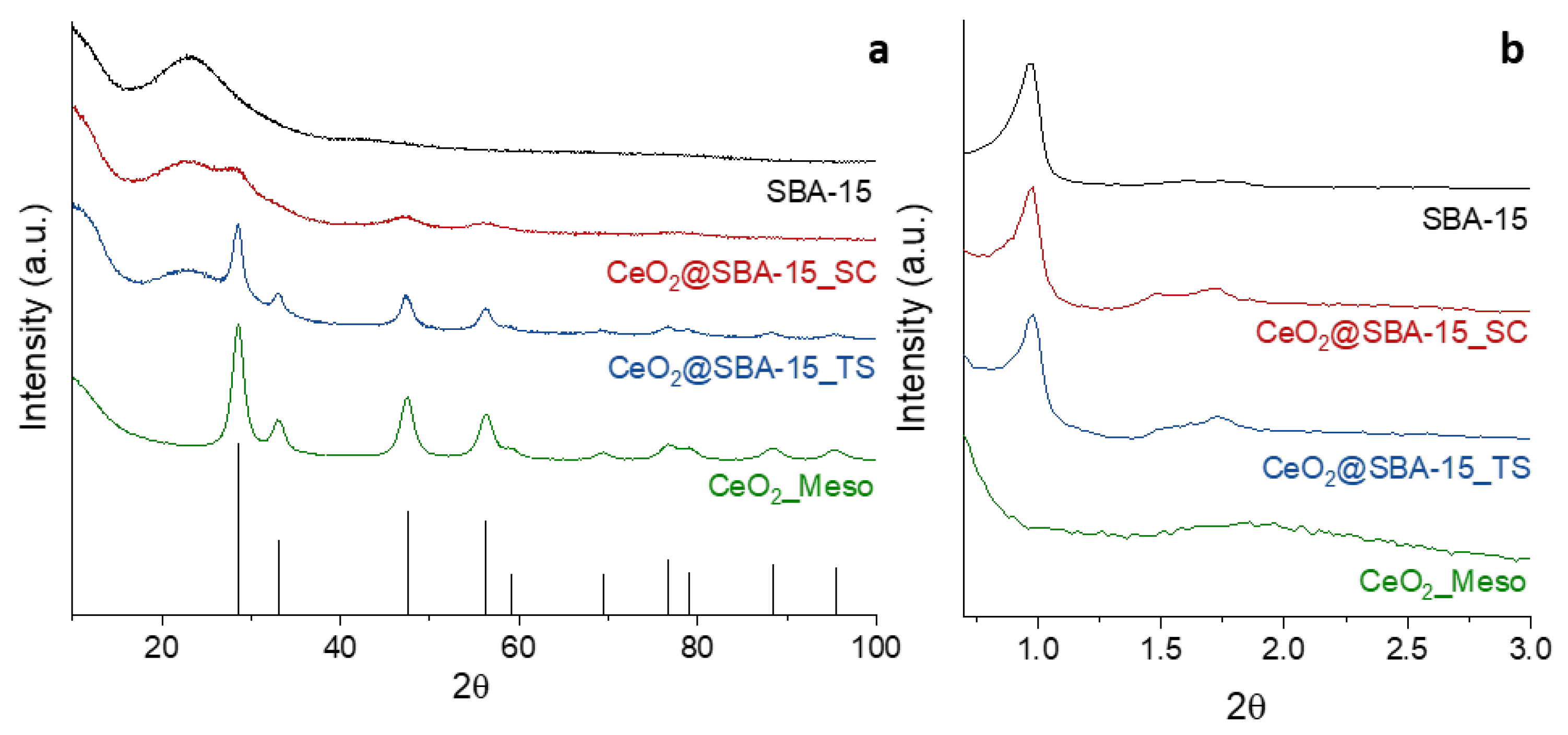
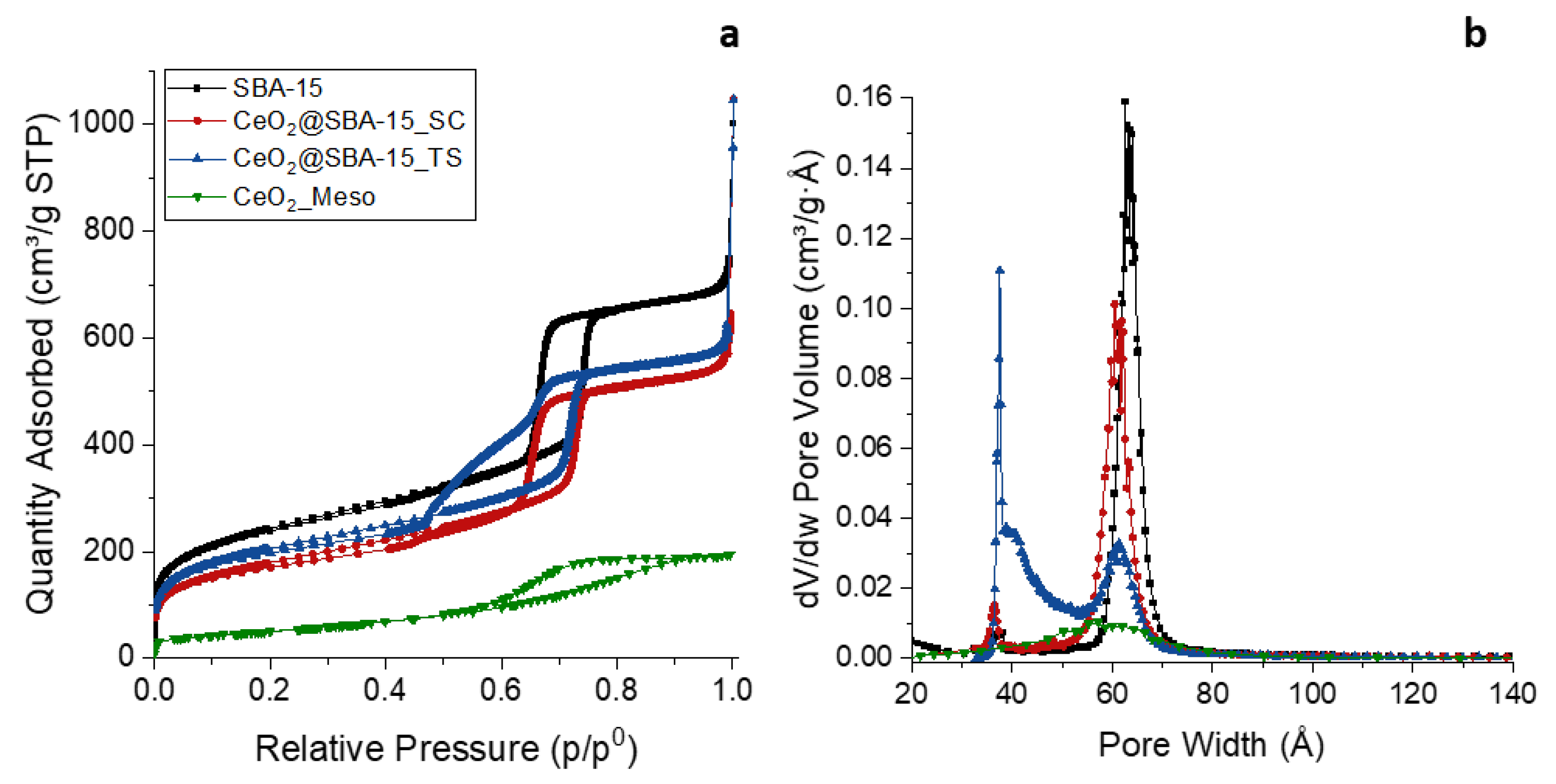

| Sample | DXRD (nm) | a0 (nm) | S.A. (m2/g) | Vp (cm3/g) | DP (nm) | Tw (nm) |
| CeO2_Meso | 7.9(1) | - | 182 | 0.27 | 5.8 | - |
| CeO2@SBA-15_TS | 7.9(1) | 10.4 | 722 | 0.93 | 6.1 | 4.3 |
| CeO2@SBA-15_SC | 2.6(1) | 10.4 | 635 | 0.88 | 6.1 | 4.3 |
| SBA-15 | - | 10.5 | 853 | 0.99 | 6.3 | 4.2 |
Disclaimer/Publisher’s Note: The statements, opinions and data contained in all publications are solely those of the individual author(s) and contributor(s) and not of MDPI and/or the editor(s). MDPI and/or the editor(s) disclaim responsibility for any injury to people or property resulting from any ideas, methods, instructions or products referred to in the content. |
© 2024 by the authors. Licensee MDPI, Basel, Switzerland. This article is an open access article distributed under the terms and conditions of the Creative Commons Attribution (CC BY) license (http://creativecommons.org/licenses/by/4.0/).


