Submitted:
04 August 2024
Posted:
06 August 2024
You are already at the latest version
Abstract
Keywords:
1. Introduction
2. Tasks and Challenges of Hydrogen Economy Towards Green Hydrogen
3. Grey, Blue, Green and Pink Hydrogen
4. Key Components and Materials of Water Electrolyzers
5. Current Technologies Used for Green Hydrogen Production
5.1. Alkaline Electrolyzers (AEs)
5.2. Proton Exchange Membrane (PEM) Electrolyzers
5.3. Solid Oxide Electrolyzers (SOEs)
5.4. Anion Exchange Membrane (AEM) Electrolyzers
6. Conclusions and Future Directions
Funding
Data Availability Statement
Conflicts of Interest
References
- Farhidi, F.; Mawi, Z. Is It Costly to Transition from Fossil Fuel Energy: A Trade-Off Analysis. Energies 2022, 15, 7873. [Google Scholar] [CrossRef]
- Hou, H.; Lu, W.; Liu, B.; Hassanein, Z.; Mahmood, H.; Khalid, S. Exploring the Role of Fossil Fuels and Renewable Energy in Determining Environmental Sustainability: Evidence from OECD Countries. Sustainability 2023, 15, 2048. [Google Scholar] [CrossRef]
- Holechek, J.L.; Geli, H.M.E.; Sawalhah, M.N.; Valdez, R. A Global Assessment: Can Renewable Energy Replace Fossil Fuels by 2050? Sustainability 2022, 14, 4792. [Google Scholar] [CrossRef]
- Gbenga Wilfred, A.; Ohonba, A. The Effects of Fossil Fuel Consumption-Related CO2 on Health Outcomes in South Africa. Sustainability 2024, 16, 4751. [Google Scholar] [CrossRef]
- Hodgson, J.R.; Benkowitz, C.; Castellani, B.C.; Ellison, A.; Yassaie, R.; Twohig, H.; Bhudia, R.; Jutila, O.-E.I.; Fowler-Davis, S. A Scoping Review of the Effects of Ambient Air Quality on Cognitive Frailty. Environments 2024, 11, 4. [Google Scholar] [CrossRef]
- Andrade, A.; D’Oliveira, A.; De Souza, L.C.; Bastos, A.C.R.d.F.; Dominski, F.H.; Stabile, L.; Buonanno, G. Effects of Air Pollution on the Health of Older Adults during Physical Activities: Mapping Review. Int. J. Environ. Res. Public Health 2023, 20, 3506. [Google Scholar] [CrossRef] [PubMed]
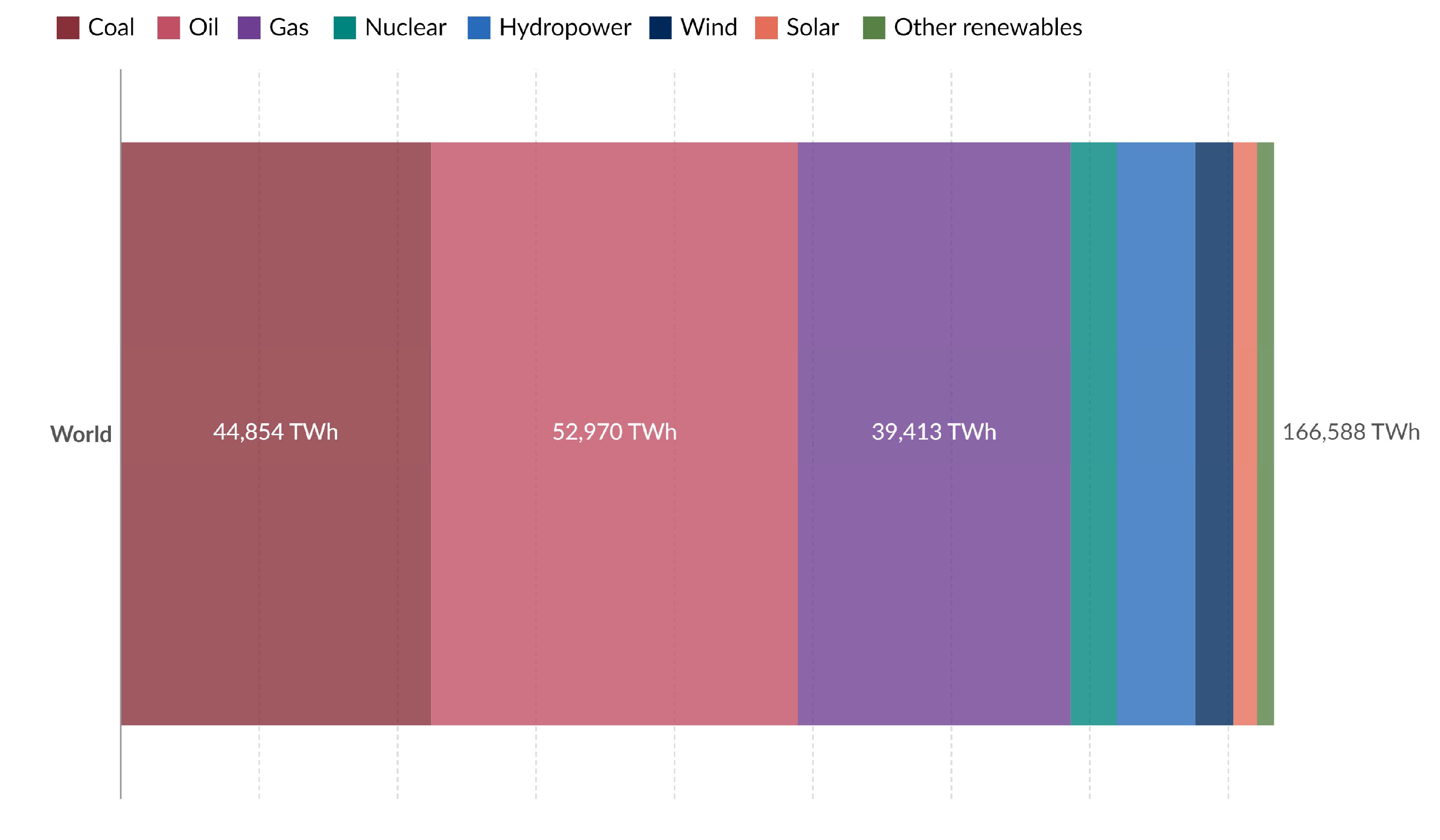
- Our World in Data. Primary Energy Consumption by Source. World. 2022. Available online: https://ourworldindata.org/grapher/primary-energy-source-bar?country=~OWID_WRL (accessed on 17 May 2024).
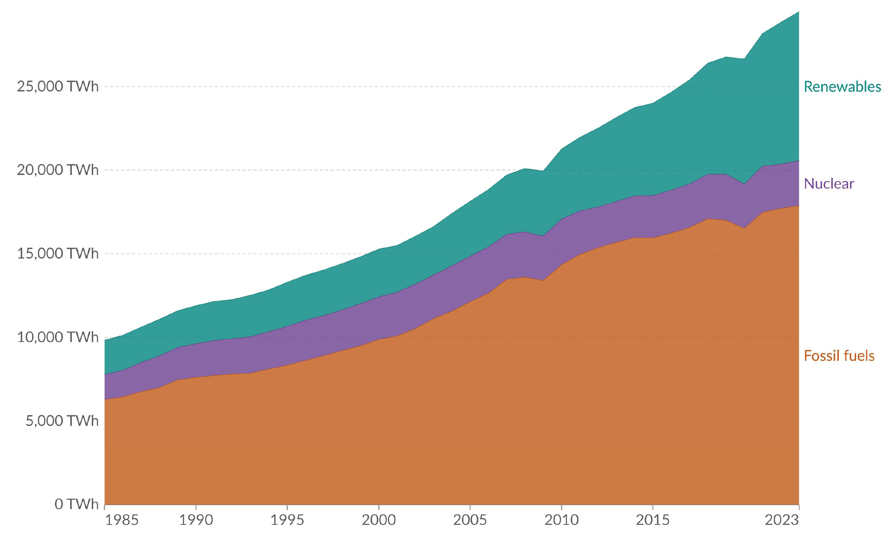
- Our World in Data. Electricity Production from Fossil Fuels, Nuclear and Renewable. World. 2023. Available online: https://ourworldindata.org/grapher/elec-fossil-nuclear-renewables (accessed on 18 May 2024).
- Our World in Data. Ritchie, H. Global renewables are growing, but have been partly offset by a decline in nuclear production. 2017. Available online: https://ourworldindata.org/global-renewables-are-growing-but-are-only-managing-to-offset-a-decline-in-nuclear-production (accessed on 18 May 2024).
- Rolo, I.; Costa, V.A.F.; Brito, F.P. Hydrogen-Based Energy Systems: Current Technology Development Status, Opportunities and Challenges. Energies 2024, 17, 180. [Google Scholar] [CrossRef]
- Ishaq, H.; Dincer, I.; Crawford, C. A review on hydrogen production and utilization: Challenges and opportunities. Int. J. Hydrogen Energy 2022, 47, 26238–26264. [Google Scholar] [CrossRef]
- Capurso, T.; Stefanizzi, M.; Torresi, M.; Camporeale, S.M. Perspective of the role of hydrogen in the 21st century energy transition. Energy Convers. Manag. 2022, 251, 114898. [Google Scholar] [CrossRef]
- Falcone, P.M.; Hiete, M.; Sapio, A. Hydrogen economy and sustainable development goals: Review and policy insights. Curr. Opin. Green Sustain. Chem. 2021, 31, 100506. [Google Scholar] [CrossRef]
- Wappler, M.; Unguder, D.; Lu, X.; Ohlmeyer, H.; Teschke, H.; Lueke, W. Building the green hydrogen market – Current state and outlook on green hydrogen demand and electrolyzer manufacturing. Int. J. Hydrogen Energy 2022, 47, 33551–33570. [Google Scholar] [CrossRef]
- Yue, M.; Lambert, H.; Pahon, E.; Roche, R.; Jemei, S.; Hissel, D. Hydrogen energy systems: A critical review of technologies, applications, trends and challenges. Renew. Sustain. Energy Rev. 2021, 146, 111180. [Google Scholar] [CrossRef]
- Qazi, U.Y. Future of Hydrogen as an Alternative Fuel for Next-Generation Industrial Applications; Challenges and Expected Opportunities. Energies 2022, 15, 4741. [Google Scholar] [CrossRef]
- Anantharaj, S.; Noda, S.; Jothi, V.R.; Yi, S.; Driess, M.; Menezes, P.W. Strategies and Perspectives to Catch the Missing Pieces in Energy-Efficient Hydrogen Evolution Reaction in Alkaline Media. Angew. Chem. Int. Ed. 2021, 60, 18981–19006. [Google Scholar] [CrossRef] [PubMed]
- Angeles-Olvera, Z.; Crespo-Yapur, A.; Rodríguez, O.; Cholula-Díaz, J.L.; Martínez, L.M.; Videa, M. Nickel-Based Electrocatalysts for Water Electrolysis. Energies 2022, 15, 1609. [Google Scholar] [CrossRef]
- Wei, Y.; Soomro, R.A.; Xie, X.; Xu, B. Design of efficient electrocatalysts for hydrogen evolution reaction based on 2D MXenes. J. Energy Chem. 2021, 55, 244–255. [Google Scholar] [CrossRef]
- Ahmed, K.W.; Jang, M.J.; Habibpour, S.; Chen, Z.; Fowler, M. NiFeOx and NiFeCoOx Catalysts for Anion Exchange Membrane Water Electrolysis. Electrochem 2022, 3, 843–861. [Google Scholar] [CrossRef]
- IRENA, 2020b. Green Hydrogen Cost Reduction: Scaling Up Electrolysers to Meet the 1.5 °C Climate Goal. International Renewable Energy Agency, Abu Dhabi, ISBN: 978-92-9260-295-6.
- Kubisztal, J.; Kubisztal, M. Pressed Ni/MFe2O4 (M = Ni, Co) powder compacts for application as bifunctional, high-performance electrodes in electrochemical water splitting. Int. J. Hydrogen Energy 2024, 56, 912–923. [Google Scholar] [CrossRef]
- Kubisztal, J.; Kubisztal, M. Synthesis and Characterisation of Cobalt Ferrite Coatings for Oxygen Evolution Reaction. Catalysts 2022, 12, 21. [Google Scholar] [CrossRef]
- Yu, W.; Huang, H.; Qin, Y.; Zhang, D.; Zhang, Y.; Liu, K.; Zhang, Y.; Lai, J.; Wang, L. The Synergistic Effect of Pyrrolic-N and Pyridinic-N with Pt Under Strong Metal-Support Interaction to Achieve High-Performance Alkaline Hydrogen Evolution. Adv. Energy Mater. 2022, 21, 2200110. [Google Scholar] [CrossRef]
- Wang, J.; Gao, Y.; Kong, H.; Kim, J.; Choi, S.; Ciucci, F.; Hao, Y.; Yang, S.; Shao, Z.; Lim, J. Non-precious-metal catalysts for alkaline water electrolysis: operando characterizations, theoretical calculations, and recent advances. Chem. Soc. Rev. 2020, 49, 9154. [Google Scholar] [CrossRef] [PubMed]
- Xie, X.; Du, L.; Yan, L.; Park, S.; Qiu, Y.; Sokolowski, J.; Wang, W.; Shao, Y. Oxygen Evolution Reaction in Alkaline Environment: Material Challenges and Solutions. Adv. Funct. Mater. 2022, 32, 2110036. [Google Scholar] [CrossRef]
- Yang, H.; Ji, Y.; Shao, Q.; Zhu, W.; Fang, M.; Ma, M.; Liao, F.; Huang, H.; Zhang, Y.; Yang, J.; Fan, Z.; Li, Y.; Liu, Y.; Shao, M.; Kang, Z. Metastable-phase platinum oxide for clarifying the Pt–O active site for the hydrogen evolution re action. Energy Environ. Sci. 2023, 16, 574. [Google Scholar] [CrossRef]
- Hülsey, M.J.; Fung, V.; Hou, X.; Wu, J.; Yan, N. Hydrogen Spillover and Its Relation to Hydrogenation: Observations on Structurally Defined Single-Atom Sites. Angew. Chem. Int. Ed. 2022, 61, e202208237. [Google Scholar] [CrossRef] [PubMed]
- Hughes, J.P.; Clipsham, J.; Chavushoglu, H.; Rowley-Neale, S.J.; Banks, C.E. Polymer electrolyte electrolysis: A review of the activity and stability of non-precious metal hydrogen evolution reaction and oxygen evolution reaction catalysts. Renew. Sustain. Energy Rev. 2021, 139, 110709. [Google Scholar] [CrossRef]
- Kuhnert, E.; Heidinger, M.; Sandu, D.; Hacker, V.; Bodner, M. Analysis of PEM Water Electrolyzer Failure Due to Induced Hydrogen Crossover in Catalyst-Coated PFSA Membranes. Membranes 2023, 13, 348. [Google Scholar] [CrossRef] [PubMed]
- Noor Azam, A.M.I.; Li, N.K.; Zulkefli, N.N.; Masdar, M.S.; Majlan, E.H.; Baharuddin, N.A.; Mohd Zainoodin, A.; Mohamad Yunus, R.; Shamsul, N.S.; Husaini, T.; et al. Parametric Study and Electrocatalyst of Polymer Electrolyte Membrane (PEM) Electrolysis Performance. Polymers 2023, 15, 560. [Google Scholar] [CrossRef] [PubMed]
- Cross, M.W.; Smith, R.P., III; Varhue, W.J. RuO2 Nanorods as an Electrocatalyst for Proton Exchange Membrane Water Electrolysis. Micromachines 2021, 12, 1412. [Google Scholar] [CrossRef] [PubMed]
- Cheng, F.; Tian, T.; Wang, R.; Zhang, H.; Zhu, L.; Tang, H. Structure–Performance Correlation Inspired Platinum-Assisted Anode with a Homogeneous Ionomer Layer for Proton Exchange Membrane Water Electrolysis. Polymers 2024, 16, 237. [Google Scholar] [CrossRef] [PubMed]
- Villamayor, A.; Alba, A.; Barrio, L.V.; Rojas, S.; Gutierrez-Berasategui, E. Magnetron Sputtered Low-Platinum Loading Electrode as HER Catalyst for PEM Electrolysis. Coatings 2024, 14, 868. [Google Scholar] [CrossRef]
- Pérez-Viramontes, N.J.; Collins-Martínez, V.H.; Escalante-García, I.L.; Flores-Hernández, J.R.; Galván-Valencia, M.; Durón-Torres, S.M. Ir-Sn-Sb-O Electrocatalyst for Oxygen Evolution Reaction: Physicochemical Characterization and Performance in Water Electrolysis Single Cell with Solid Polymer Electrolyte. Catalysts 2020, 10, 524. [Google Scholar] [CrossRef]
- Vibhu, V.; Vinke, I.C.; Eichel, R.-A.; de Haart, L.G.J. La0.6Sr0.4MnO3-Based Fuel Electrode Materials for Solid Oxide Electrolysis Cells Operating under Steam, CO2, and Co-Electrolysis Conditions. Energies 2023, 16, 7115. [Google Scholar] [CrossRef]
- Srinivas, S.; Dhanushkodi, S.R.; Chidambaram, R.K.; Skrzyniowska, D.; Korzen, A.; Taler, J. Benchmarking Electrolytes for the Solid Oxide Electrolyzer Using a Finite Element Model. Energies 2023, 16, 6419. [Google Scholar] [CrossRef]
- Wierzbicki, M.; Jagielski, S.; Naumovich, Y.; Niemczyk, A.; Skrzypkiewicz, M.; Kupecki, J. Impact of Sweep Gas on the Degradation of an La0.6Sr0.4Co0.8Fe0.8O3 Anode in a Solid Oxide Electrolysis Cell. Energies 2024, 17, 1144. [Google Scholar] [CrossRef]
- Budiman, R.A.; Konishi, R.; Bisaka, N.; Yashiro, K.; Kawada, T. Time-Dependence of Microstructural Evolution and Performance Degradation of Ni/YSZ Electrode in Co-Electrolysis SOEC. ECS Trans. 2023, 111, 1509. [Google Scholar] [CrossRef]
- Rorato, L.; Shang, Y.; Yang, S.; Hubert, M.; Couturier, K.; Zhang, L.; Vulliet, J.; Chen, M.; Laurencin, J. Understanding the Ni Migration in Solid Oxide Cell: A Coupled Experimental and Modeling Approach. J. Electrochem. Soc. 2023, 170. [Google Scholar] [CrossRef]
- Shang, Y.; Smitshuysen, A.L.; Yu, M.; Liu, Y.; Tong, X.; Jørgensen, P.S.; Rorato, L.; Laurencin, J.; Chen, M. 3D microstructural characterization of Ni/yttria-stabilized zirconia electrodes during long-term CO2 electrolysis. J. Mater. Chem. A 2023, 11, 12245–12257. [Google Scholar] [CrossRef]
- Mogensen, M.B.; Chen, M.; Frandsen, H.L.; Graves, C.; Hauch, A.; Hendriksen, P.V.; Jacobsen, T.; Jensen, S.H.; Skafte, T.L.; Sun, X. Ni migration in solid oxide cell electrodes: Review and revised hypothesis. Fuel Cells 2021, 21, 415–429. [Google Scholar] [CrossRef]
- Unachukwu, I.D.; Vibhu, V.; Uecker, J.; Vinke, I.C.; Eichel, R.-A.; de Haart, L.G.J. Electrochemical impedance analysis and degradation behavior of a Ni-GDC fuel electrode containing single cell in direct CO2 electrolysis. J. CO2 Util. 2023, 69, 102423. [Google Scholar] [CrossRef]
- Uecker, J.; Unachukwu, I.D.; Vibhu, V.; Vinke, I.C.; Eichel, R.-A.; de Haart, L.G.J. Performance, electrochemical process analysis and degradation of gadolinium doped ceria as fuel electrode material for solid oxide electrolysis cells. Electrochim. Acta 2023, 452, 142320. [Google Scholar] [CrossRef]
- Unachukwu, I.D.; Vibhu, V.; Uecker, J.; Vinke, I.C.; Eichel, R.-A.; de Haart, L.G.J. Comparison of the Electrochemical and Degradation Behaviour of Ni-YSZ and Ni-GDC Electrodes Under Steam, Co- and CO2 Electrolysis. ECS Trans. 2023, 111, 1445. [Google Scholar] [CrossRef]
- Vibhu, V.; Vinke, I.C.; Zaravelis, F.; Neophytides, S.G.; Niakolas, D.K.; Eichel, R.-A.; de Haart, L.G.J. Performance and Degradation of Electrolyte-Supported Single Cell Composed of Mo-Au-Ni/GDC Fuel Electrode and LSCF Oxygen Electrode during High Temperature Steam Electrolysis. Energies 2022, 15, 2726. [Google Scholar] [CrossRef]
- Sala, E.M.; Mazzanti, N.; Mogensen, M.B.; Chatzichristodoulou, C. Current understanding of ceria surfaces for CO2 reduction in SOECs and future prospects–A review. Solid State Ion. 2022, 375, 115833. [Google Scholar] [CrossRef]
- Vafaeenezhad, S.; Hanifi, A.R.; Laguna-Bercero, M.A.; Etsell, T.H.; Sarkar, P. Microstructure and long-term stability of Ni–YSZ anode supported fuel cells: A review. Mater. Futures 2022, 1, 042101. [Google Scholar] [CrossRef]
- Guo, D.; Chi, J.; Yu, H.; Jiang, G.; Shao, Z. Self-Supporting NiFe Layered Double Hydroxide “Nanoflower” Cluster Anode Electrode for an Efficient Alkaline Anion Exchange Membrane Water Electrolyzer. Energies 2022, 15, 4645. [Google Scholar] [CrossRef]
- Ahmed, K.W.; Jang, M.J.; Habibpour, S.; Chen, Z.; Fowler, M. NiFeOx and NiFeCoOx Catalysts for Anion Exchange Membrane Water Electrolysis. Electrochem 2022, 3, 843–861. [Google Scholar] [CrossRef]
- Tardy, E.; Bultel, Y.; Druart, F.; Bonnefont, A.; Guillou, M.; Latour, B. Three-Dimensional Modeling of Anion Exchange Membrane Electrolysis: A Two-Phase Flow Approach. Energies 2024, 17, 3238. [Google Scholar] [CrossRef]
- Vinodh, R.; Kalanur, S.S.; Natarajan, S.K.; Pollet, B.G. Recent Advancements of Polymeric Membranes in Anion Exchange Membrane Water Electrolyzer (AEMWE): A Critical Review. Polymers 2023, 15, 2144. [Google Scholar] [CrossRef] [PubMed]
- Li, D.; Motz, A.R.; Bae, C.; Fujimoto, C.; Yang, G.; Zhang, F.; Ayers, K.E.; Kim, Y.S. Durability of anion exchange membrane water electrolyzers. Energy Environ. Sci. 2021, 14, 3393. [Google Scholar] [CrossRef]
- Rossini, M.; Pan, D.; Koyutürk, B.; Chen, S.; Khataee, A.; Lindbergh, G.; Jannasch, P.; Ann Cornell, A. High performance water electrolysis using a poly(fluorene phenylpropylammonium) anion-exchange membrane with 2 M aqueous KOH. J. Mater. Chem. A 2024, 12, 12826–12834. [Google Scholar] [CrossRef]
- Wijaya, G.H.A.; Im, K.S.; Nam, S.Y. Advancements in commercial anion exchange membranes: A review of membrane properties in water electrolysis applications. Desalin. Water Treat. 2024, 320, 100605. [Google Scholar] [CrossRef]
- Li, S.; Liu, T.; Zhang, W.; et al. Highly efficient anion exchange membrane water electrolyzers via chromium-doped amorphous electrocatalysts. Nat Commun 2024, 15, 3416. [Google Scholar] [CrossRef] [PubMed]
- Kim, S.; Yang, S.H.; Shin, S-H.; Cho, H.J.; Jang, J.K.; Kim, T.H.; Oh, S-G.; Kim, T-H.; Han, H.S.; Lee, J.Y. High-performance and durable anion-exchange membrane water electrolysers with high-molecular-weight polycarbazole-based anion-conducting polymer. Energy Environ. Sci. 2024, 17, 5399–5409. [Google Scholar] [CrossRef]
- Ranz, M.; Grabner, B.; Schweighofer, B.; Wegleiter, H.; Trattner, A. Dynamics of anion exchange membrane electrolysis: Unravelling loss mechanisms with electrochemical impedance spectroscopy, reference electrodes and distribution of relaxation times. J. Power Sources 2024, 605, 234455. [Google Scholar] [CrossRef]
- Patnaik, S.; Sahoo, D.P.; Parida, K. Recent advances in anion doped g-C3N4 photocatalysts: a review. Carbon. 2021, 172, 682–711. [Google Scholar] [CrossRef]
- Theerthagiri, J.; Karuppasamy, K.; Lee, S.J.; Shwetharani, R.; Kim, H.; Pasha, S.K.K.; Ashokkumar, M.; Choi, M.Y. Fundamentals and comprehensive insights on pulsed laser synthesis of advanced materials for diverse photo- and electrocatalytic applications. Light Sci. Appl. 2022, 11, 250. [Google Scholar] [CrossRef] [PubMed]
- Zhu, B.; Cheng, B.; Fan, J.; Ho, W.; Yu, J. g-C3N4-based 2D/2D composite heterojunction photocatalyst. Small Structures. 2021, 2, 2100086. [Google Scholar] [CrossRef]
- Liu, S.; Wang, M.; He, Y.; Cheng, Q.; Qian, T.; Yan, C. Covalent organic frameworks towards photocatalytic applications: Design principles, achievements, and opportunities. Coord. Chem. Rev. 2023, 475, 214882. [Google Scholar] [CrossRef]
- Murali, G.; Modigunta, J.K.R.; Park, Y.H.; Lee, J.; Rawal, J.; Lee, S.; In, I.; Park, S. A Review on MXene Synthesis, Stability, and Photocatalytic Applications. ACS Nano 2022, 16, 13370–13429. [Google Scholar] [CrossRef] [PubMed]
- Zhu, Q.; Xu, Q.; Du, M.; Zeng, X.; Zhong, G.; Qiu, B.; Zhang, J. Recent Progress of Metal Sulfide Photocatalysts for Solar Energy Conversion. Adv. Mater. 2022, 34, 2202929. [Google Scholar] [CrossRef] [PubMed]
- Foo, J.J.; Ng, S.; Ong, W. Dimensional heterojunction design: The rising star of 2D bismuth-based nanostructured photocatalysts for solar-to-chemical conversion. Nano Res. 2023, 16, 4310–4364. [Google Scholar] [CrossRef]
- Osman, A.I.; Elgarahy, A.M.; Eltaweil, A.S.; El-Monaem, E.M.A.; El-Aqapa, H.G.; Park, Y.; Hwang, Y.; Ayati, A.; Farghali, M.; Ihara, I.; Al-Muhtaseb, A.H.; Rooney, D.W.; Yap, P.; Sillanpää, M. Biofuel production, hydrogen production and water remediation by photocatalysis, biocatalysis and electrocatalysis. Environ. Chem. Lett. 2023, 21, 1315–1379. [Google Scholar] [CrossRef]
- Aslam, A.; Bahadar, A.; Liaquat, R.; Muddasar, M. Recent advances in biological hydrogen production from algal biomass: A comprehensive review. Fuel 2023, 350, 128816. [Google Scholar] [CrossRef]
- Zhang, Q.; Jiao, Y.; He, C.; et al. Biological fermentation pilot-scale systems and evaluation for commercial viability towards sustainable biohydrogen production. Nat. Commun. 2024, 15, 4539. [Google Scholar] [CrossRef] [PubMed]
- Dari, D.N.; Freitas, I.S.; Aires, F.I.d.S.; Melo, R.L.F.; dos Santos, K.M.; da Silva Sousa, P.; Gonçalves de Sousa Junior, P.; Luthierre Gama Cavalcante, A.; Neto, F.S.; da Silva, J.L.; et al. An Updated Review of Recent Applications and Perspectives of Hydrogen Production from Biomass by Fermentation: A Comprehensive Analysis. Biomass 2024, 4, 132–163. [Google Scholar] [CrossRef]
- Worku, A.K.; Ayele, D.W.; Deepak, D.B.; Gebreyohannes, A.Y.; Agegnehu, S.D.; Kolhe, M.L. Recent Advances and Challenges of Hydrogen Production Technologies via Renewable Energy Sources. Adv. Energ. Sust. Res. 2024, 5, 2300273. [Google Scholar] [CrossRef]
- Samrot, A.V.; Rajalakshmi, D.; Sathiyasree, M.; Saigeetha, S.; Kasipandian, K.; Valli, N.; Jayshree, N.; Prakash, P.; Shobana, N. A Review on Biohydrogen Sources, Production Routes, and Its Application as a Fuel Cell. Sustainability 2023, 15, 12641. [Google Scholar] [CrossRef]
- Hassan, Q.; Hafedh, S.A.; Mohammed, H.B.; Abdulrahman, I.S.; Salman, H.M. and Jaszczur, Ma. A review of hydrogen production from bio-energy, technologies and assessments. Energy Harvest. Syst. 2024, 11, 20220117. [Google Scholar] [CrossRef]
- Fallah Vostakola, M.; Ozcan, H.; El-Emam, R.S.; Amini Horri, B. Recent Advances in High-Temperature Steam Electrolysis with Solid Oxide Electrolysers for Green Hydrogen Production. Energies 2023, 16, 3327. [Google Scholar] [CrossRef]
- Yuan, J.; Li, Z.; Yuan, B.; Xiao, G.; Li, T.; Wang, J.-Q. Optimization of High-Temperature Electrolysis System for Hydrogen Production Considering High-Temperature Degradation. Energies 2023, 16, 2616. [Google Scholar] [CrossRef]
- Riester, C.M.; García, G.; Alayo, N.; Tarancón, A.; Santos, D.M.F.; Torrell, M. Business Model Development for a High-Temperature (Co-)Electrolyser System. Fuels 2022, 3, 392–407. [Google Scholar] [CrossRef]
- Wolf, S.E.; Vibhu, V.; Tröster, E.; Vinke, I.C.; Eichel, R.-A.; de Haart, L.G.J. Steam Electrolysis vs. Co-Electrolysis: Mechanistic Studies of Long-Term Solid Oxide Electrolysis Cells. Energies 2022, 15, 5449. [Google Scholar] [CrossRef]
- Afroze, S.; Sofri, A.N.S.B.; Reza, M.S.; Iskakova, Z.B.; Kabyshev, A.; Kuterbekov, K.A.; Bekmyrza, K.Z.; Taimuratova, L.; Uddin, M.R.; Azad, A.K. Solar-Powered Water Electrolysis Using Hybrid Solid Oxide Electrolyzer Cell (SOEC) for Green Hydrogen—A Review. Energies 2023, 16, 7794. [Google Scholar] [CrossRef]
- Yuan, J.; Li, Z.; Yuan, B.; Xiao, G.; Li, T.; Wang, J.-Q. Optimization of High-Temperature Electrolysis System for Hydrogen Production Considering High-Temperature Degradation. Energies 2023, 16, 2616. [Google Scholar] [CrossRef]
- Bollmann, J.; Pitchaimuthu, S.; Kühnel, M.F. Challenges of Industrial-Scale Testing Infrastructure for Green Hydrogen Technologies. Energies 2023, 16, 3604. [Google Scholar] [CrossRef]
- IRENA, 2020a. Green Hydrogen: A Guide to Policy Making. International Renewable Energy Agency, Abu Dhabi, ISBN: 978-92-9260-286-4.
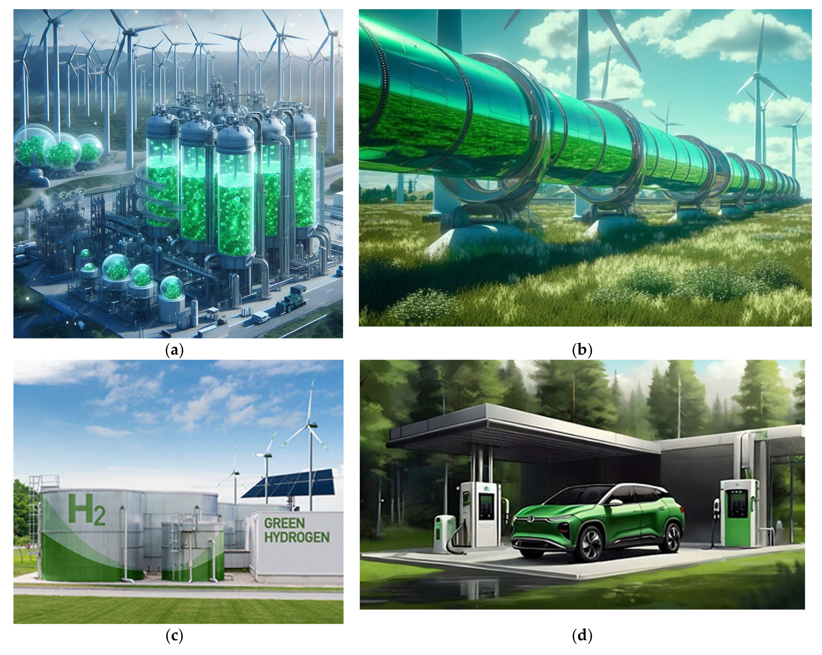
- A concept of green hydrogen production through water electrolysis supporting a decarbonized future. https://www.freepik.com/premium-ai-image/concept-green-hydrogen-production-through-water-electrolysis-supporting-decarbonized-future_188163710.htm#from_view=detail_alsolike. (accessed on 24 May 2024).
- Green hydrogen pipeline wind turbines in modern style. https://www.freepik.com/premium-photo/green-hydrogen-pipeline-wind-turbines-modern-style-modern-concept-design-green-energy-production-electricity-equipment-generative-ai_48963318.htm#fromView=search&page=1&position=44&uuid=13cb16fb-c1ad-46f5-847a-519491d425b3. (accessed on 24 May 2024).
- Green Hydrogen factory concept. Hydrogen production from renewable energy sources. https://www.shutterstock.com/image-photo/green-hydrogen-factory-concept-production-renewable-2280474099?irclickid=U4FyqUVm0xyPUWHWwGQTwTn7UkHVCyxIPQcV2Q0&irgwc=1&pl=4869764-1906897&utm_campaign=Freepik%20Company&utm_content=1906897&utm_medium=Affiliate&utm_source=4869764&utm_term=www.freepik.com. (accessed on 24 May 2024).
- Green hydrogen gas production at wind farm in forest, Sustainable renewable energy, sketch illustration of Electric car filling H2 at hydrogen fueling station, Net zero emission, future emission. https://stock.adobe.com/search?k=%22sketch+drawing%22&asset_id=721796374. (accessed on 24 May 2024).
- Athia, N.; Pandey, M.; Sen, M.; Saxena, S. Factors affecting the production cost of green hydrogen and its challenge for sustainable development. Environ. Dev. Sustain. 2024. [Google Scholar] [CrossRef]
- Dash, S.K.; Chakraborty, S.; Elangovan, D. A Brief Review of Hydrogen Production Methods and Their Challenges. Energies 2023, 16, 1141. [Google Scholar] [CrossRef]
- Megía, P.J.; Vizcaíno, A.J.; Calles, J.A.; Carrero, A. Hydrogen Production Technologies: From Fossil Fuels toward Renewable Sources. A Mini Review. Energy Fuels 2021, 35, 20–16403. [Google Scholar] [CrossRef]
- Yu, Z.; Duan, Y.; Feng, X.; Yu, X.; Gao, M.; Yu, S. Clean and Affordable Hydrogen Fuel from Alkaline Water Splitting: Past, Recent Progress, and Future Prospects. Adv. Mater. 2021, 33, 2007100. [Google Scholar] [CrossRef] [PubMed]
- Nasser, M.; Megahed, T.F.; Ookawara, S.; Hassan, H. A review of water electrolysis–based systems for hydrogen production using hybrid/solar/wind energy systems. Environ. Sci. Pollut. Res. 2022, 29, 86994–87018. [Google Scholar] [CrossRef]
- Lee, H.; Lee, S. Economic Analysis on Hydrogen Pipeline Infrastructure Establishment Scenarios: Case Study of South Korea. Energies 2022, 15, 6824. [Google Scholar] [CrossRef]
- Klopčič, N.; Stöhr, T.; Grimmer, I.; Sartory, M.; Trattner, A. Refurbishment of Natural Gas Pipelines towards 100% Hydrogen—A Thermodynamic-Based Analysis. Energies 2022, 15, 9370. [Google Scholar] [CrossRef]
- Khwaja, S.A.; Paul, S. Inspection of Coated Hydrogen Transportation Pipelines. Appl. Sci. 2022, 12, 9503. [Google Scholar] [CrossRef]
- Mahajan, D.; Tan, K.; Venkatesh, T.; Kileti, P.; Clayton, C.R. Hydrogen Blending in Gas Pipeline Networks—A Review. Energies 2022, 15, 3582. [Google Scholar] [CrossRef]
- Ban, J.; Yan, X.; Song, B.; Deng, S.; Wu, H.; Tang, Y.; Yin, W. Research Progress and Prospects on Hydrogen Damage in Welds of Hydrogen-Blended Natural Gas Pipelines. Processes 2023, 11, 3180. [Google Scholar] [CrossRef]
- Hassan, I.A.; Ramadan, H.S.; Saleh, M.A.; Hissel, D. Hydrogen storage technologies for stationary and mobile applications: Review, analysis and perspectives. Renew. Sustain. Energy Rev. 2021, 149, 111311. [Google Scholar] [CrossRef]
- Li, J.; Chai, X.; Gu, Y.; Zhang, P.; Yang, X.; Wen, Y.; Xu, Z.; Jiang, B.; Wang, J.; Jin, G.; et al. Small-Scale High-Pressure Hydrogen Storage Vessels: A Review. Materials 2024, 17, 721. [Google Scholar] [CrossRef] [PubMed]
- Shin, H.K.; Ha, S.K. A Review on the Cost Analysis of Hydrogen Gas Storage Tanks for Fuel Cell Vehicles. Energies 2023, 16, 5233. [Google Scholar] [CrossRef]
- Kim, M.-S.; Jeon, H.-K.; Lee, K.-W.; Ryu, J.-H.; Choi, S.-W. Analysis of Hydrogen Filling of 175 Liter Tank for Large-Sized Hydrogen Vehicle. Appl. Sci. 2022, 12, 4856. [Google Scholar] [CrossRef]
- Alves, M.P.; Gul, W.; Cimini Junior, C.A.; Ha, S.K. A Review on Industrial Perspectives and Challenges on Material, Manufacturing, Design and Development of Compressed Hydrogen Storage Tanks for the Transportation Sector. Energies 2022, 15, 5152. [Google Scholar] [CrossRef]
- Cao, Z.; Habermann, F.; Burkmann, K.; Felderhoff, M.; Mertens, F. Unstable Metal Hydrides for Possible On-Board Hydrogen Storage. Hydrogen 2024, 5, 241–279. [Google Scholar] [CrossRef]
- Rampai, M.M.; Mtshali, C.B.; Seroka, N.S.; Khotseng, L. Hydrogen production, storage, and transportation: recent advances. RSC Adv. 2024, 14, 6699–6718. [Google Scholar] [CrossRef] [PubMed]
- Bosu, S.; Natarajan Rajamohan, N. Recent advancements in hydrogen storage - Comparative review on methods, operating conditions and challenges. Int. J. Hydrogen Energy 2024, 52, Part C. 352–370. [Google Scholar] [CrossRef]
- Khan, M.M.K.; Azad, A.K.; Oo, A.M.T. Hydrogen Energy Conversion and Management, 1st ed.; Elsevier Inc., 2023. [CrossRef]
- Hoelzen, J.; Silberhorn, D.; Zill, T.; Bensmann, B.; Hanke-Rauschenbach, R. Hydrogen-powered aviation and its reliance on green hydrogen infrastructure – Review and research gaps. Int. J. Hydrogen Energy 2022, 47, 3108–3130. [Google Scholar] [CrossRef]
- Marouani, I.; Guesmi, T.; Alshammari, B.M.; Alqunun, K.; Alzamil, A.; Alturki, M.; Hadj Abdallah, H. Integration of Renewable-Energy-Based Green Hydrogen into the Energy Future. Processes 2023, 11, 2685. [Google Scholar] [CrossRef]
- Klopčič, N.; Grimmer, I.; Winkler, F.; Sartory, M.; Trattner, A. A review on metal hydride materials for hydrogen storage. J. Energy Storage 2023, 72, Part B, 108456. [Google Scholar] [CrossRef]
- Hájková, P.; Horník, J.; Čižmárová, E.; Kalianko, F. Metallic Materials for Hydrogen Storage—A Brief Overview. Coatings 2022, 12, 1813. [Google Scholar] [CrossRef]
- Liu, J.; Sun, L.; Yang, J.; Guo, D.; Chen, D.; Yang, L.; Xiao, P. Ti–Mn hydrogen storage alloys: from properties to applications. RSC Adv. 2022, 12(55), 35744–35755. [Google Scholar] [CrossRef] [PubMed]
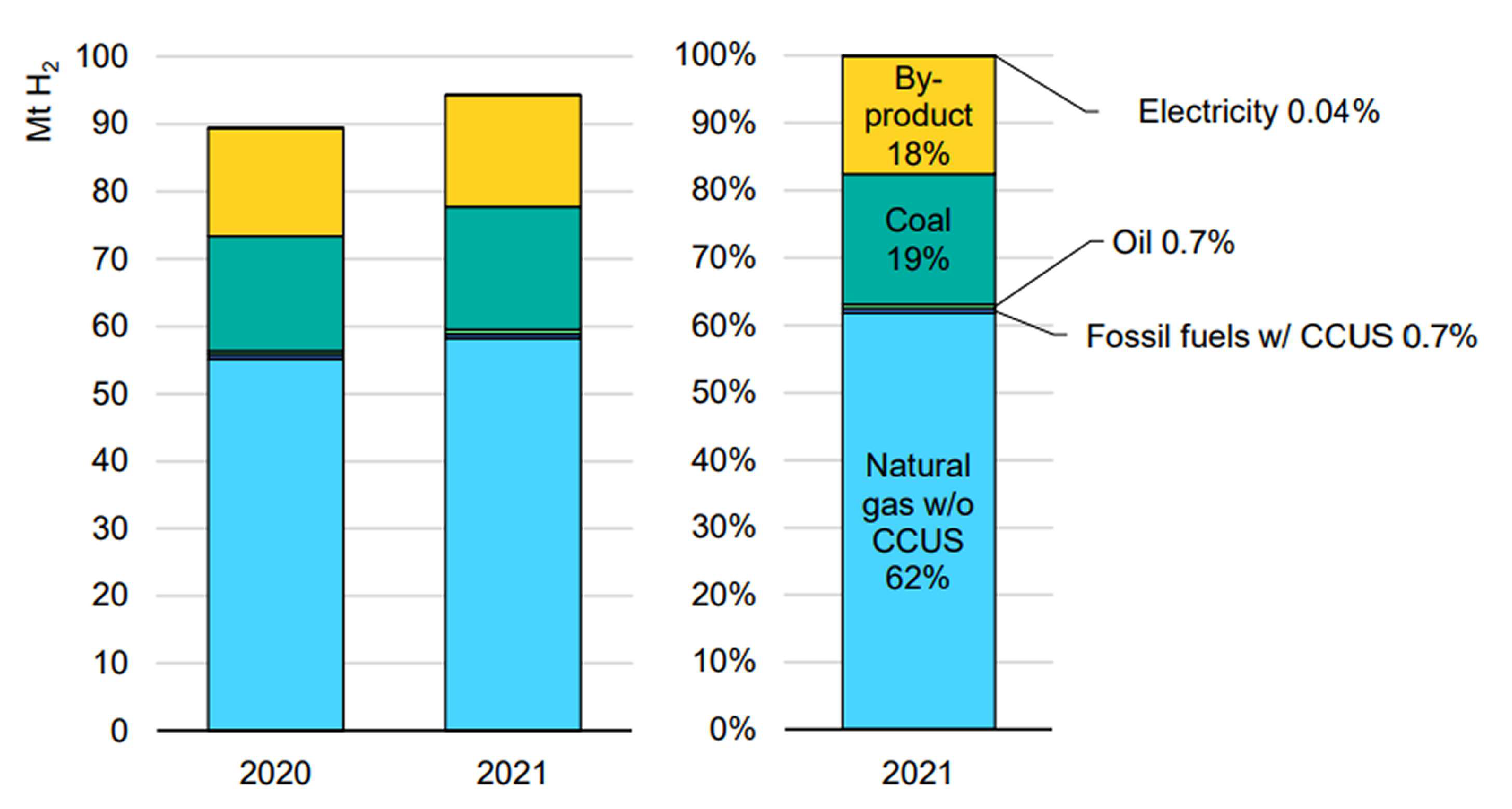
- International Energy Agency. Global Hydrogen Review 2022, IEA, Paris, Licence: CC BY 4.0. https://www.iea.org/reports/global-hydrogen-review-2022.
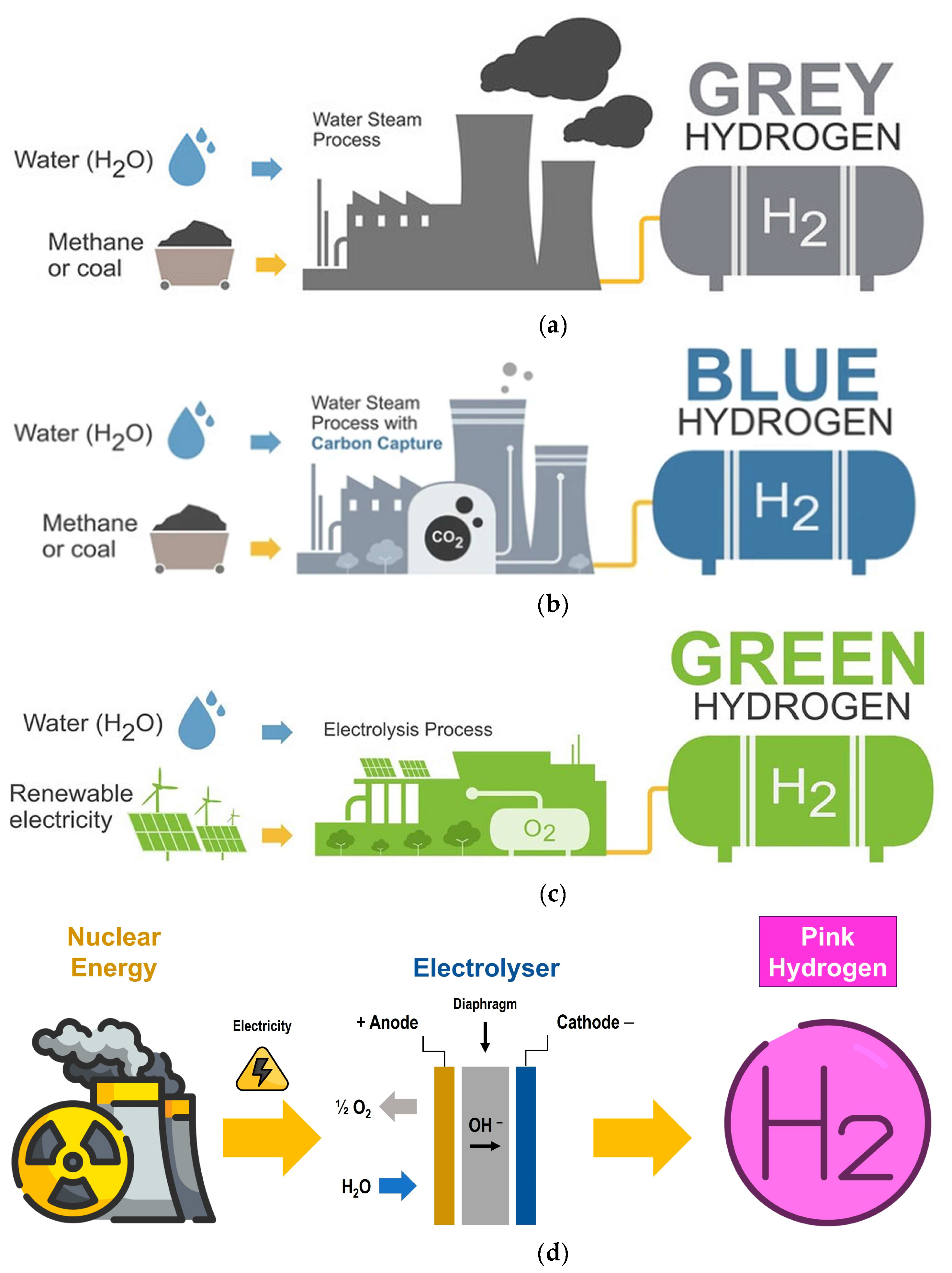
- Type of hydrogen production grey color. https://www.shutterstock.com/image-vector/type-hydrogen-production-grey-color-electrolysis-2264840099?irclickid=U4FyqUVm0xyPUWHWwGQTwTn7UkHVC31wPQcV2Q0&irgwc=1&pl=4869764-1906897&utm_campaign=Freepik%20Company&utm_content=1906897&utm_medium=Affiliate&utm_source=4869764&utm_term=www.freepik.com. (accessed on 25 May 2024).
- Type of hydrogen production blue color https://www.shutterstock.com/image-vector/type-hydrogen-production-blue-color-electrolysis-2264840095. (accessed on 25 May 2024).
- Type of hydrogen production green color. https://www.freepik.com/premium-vector/type-hydrogen-production-green-color-electrolysis-ecology-clean-energy-how-work-diagram_38581556.htm. (accessed on 25 May 2024).
- Fernández-Arias, P.; Antón-Sancho, Á.; Lampropoulos, G.; Vergara, D. Emerging Trends and Challenges in Pink Hydrogen Research. Energies 2024, 17, 2291. [Google Scholar] [CrossRef]
- Fatigati, F.; Di Giuliano, A.; Carapellucci, R.; Gallucci, K.; Cipollone, R. Experimental Characterization and Energy Performance Assessment of a Sorption-Enhanced Steam–Methane Reforming System. Processes 2021, 9, 1440. [Google Scholar] [CrossRef]
- Wang, J.; Liu, Z.; Ji, C.; Liu, L. Heat Transfer and Reaction Characteristics of Steam Methane Reforming in a Novel Composite Packed Bed Microreactor for Distributed Hydrogen Production. Energies 2023, 16, 4347. [Google Scholar] [CrossRef]
- Hermesmann, M.; Müller, T.E. Green, Turquoise, Blue, or Grey? Environmentally friendly Hydrogen Production in Transforming Energy Systems. Prog. Energ. Combust. Science 2022, 90, 100996. [Google Scholar] [CrossRef]
- Noussan, M.; Raimondi, P.P.; Scita, R.; Hafner, M. The Role of Green and Blue Hydrogen in the Energy Transition—A Technological and Geopolitical Perspective. Sustainability 2021, 13, 298. [Google Scholar] [CrossRef]
- Wang, S.; Lu, A. & Zhong, CJ. Hydrogen production from water electrolysis: role of catalysts. Nano Converg. 2021, 8, 4. [Google Scholar] [CrossRef] [PubMed]
- Global Hydrogen Generation Market Size Report, 2030. Horizon Databook. 2023.
- Franco, A.; Giovannini, C. Recent and Future Advances in Water Electrolysis for Green Hydrogen Generation: Critical Analysis and Perspectives. Sustainability 2023, 15, 16917. [Google Scholar] [CrossRef]
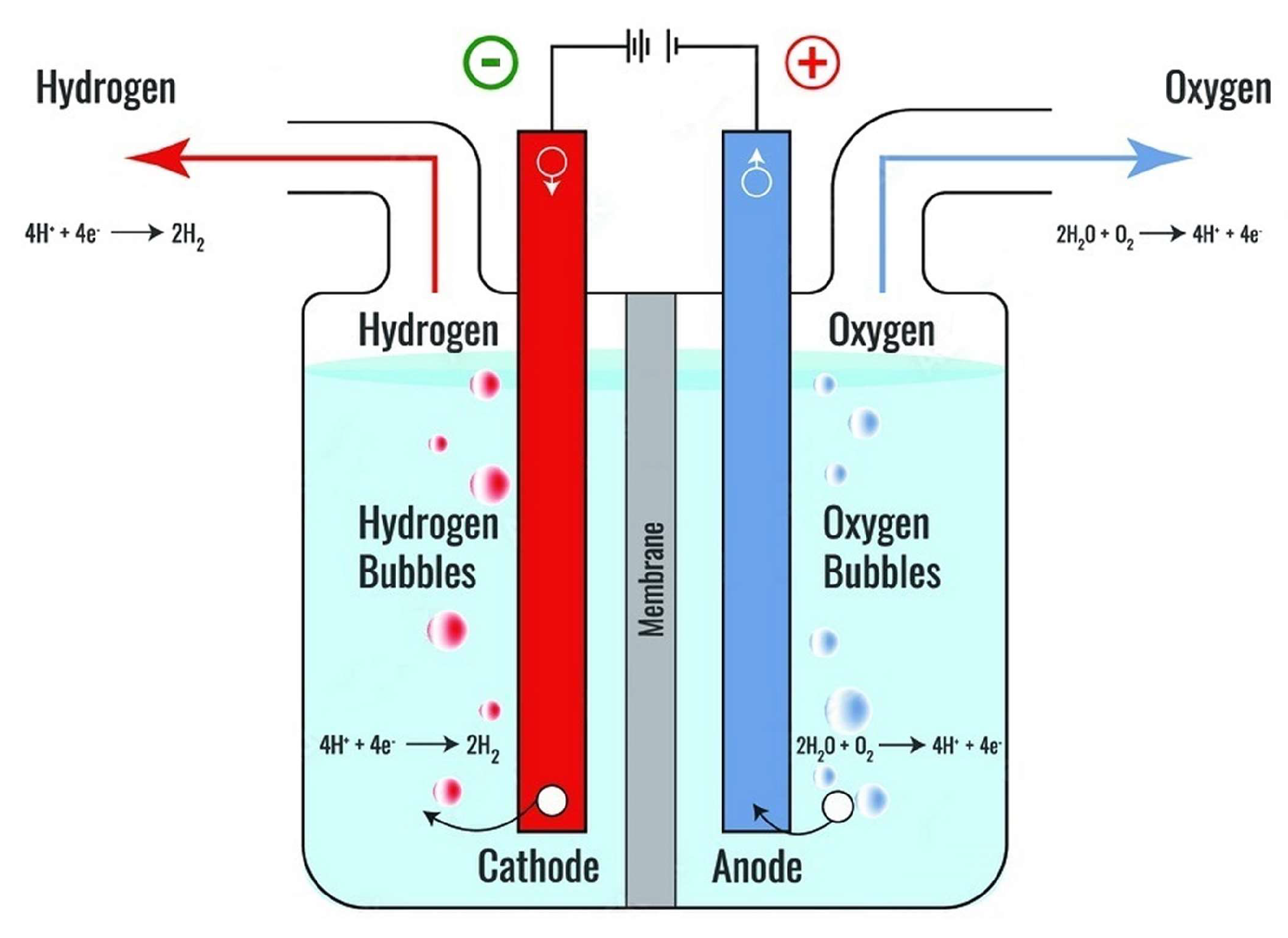
- Electrolysis of water forming hydrogen and oxygen vector illustration. https://stock.adobe.com/pl/search?get_facets=1&order=relevance&safe_search=1&search_page=1&k=electrolysis+of+water&filters%5Bcontent_type%3Azip_vector%5D=1&clickref=1101lyy5uV97&mv=affiliate&mv2=Freepik&as_camptype=&as_channel=affiliate&as_source=partnerize&as_campaign=Freepik&as_content=api&as_audience=srp&sdid=6WTV6YJ5&asset_id=508554505. (accessed on 25 May 2024).
- López-Fernández, E.; Sacedón, C.G.; Gil-Rostra, J.; Yubero, F.; González-Elipe, A.R.; de Lucas-Consuegra, A. Recent Advances in Alkaline Exchange Membrane Water Electrolysis and Electrode Manufacturing. Molecules 2021, 26, 6326. [Google Scholar] [CrossRef] [PubMed]
- Gambou, F.; Guilbert, D.; Zasadzinski, M.; Rafaralahy, H. A Comprehensive Survey of Alkaline Electrolyzer Modeling: Electrical Domain and Specific Electrolyte Conductivity. Energies 2022, 15, 3452. [Google Scholar] [CrossRef]
- Shiva Kumar, S.; Lim, H. An overview of water electrolysis technologies for green hydrogen production. Energy Reports 2022, 8, 13793–13813. [Google Scholar] [CrossRef]
- Xie, X.; Du, L.; Yan, L.; Park, S.; Qiu, Y.; Sokolowski, J.; Wang, W.; Shao, Y. Oxygen Evolution Reaction in Alkaline Environment: Material Challenges and Solutions. Adv. Funct. Mater. 2022, 32, 2110036. [Google Scholar] [CrossRef]
- Lao, M.; Li, P.; Jiang, Y.; Pan, H.; Dou, S.X.; Sun, W. From fundamentals and theories to heterostructured electrocatalyst design: An in-depth understanding of alkaline hydrogen evolution reaction. Nano Energy 2022, 98, 107231. [Google Scholar] [CrossRef]
- Alkaline electrolyzer and water isolated. https://stock.adobe.com/pl/images/id/818720025?clickref=1101lyKmqIyD&mv=affiliate&mv2=Freepik&as_camptype=&as_channel=affiliate&as_source=partnerize&as_campaign=Freepik&as_content=api&as_audience=404&sdid=6WTV6YJ5. (accessed on 6 July 2024).
- Yodwong, B.; Guilbert, D.; Phattanasak, M.; Kaewmanee, W.; Hinaje, M.; Vitale, G. Proton Exchange Membrane Electrolyzer Modeling for Power Electronics Control: A Short Review. C 2020, 6, 29. [Google Scholar] [CrossRef]
- Wang, Y.; Pang, Y.; Xu, H.; Martinez, A.; Chen, K.S. PEM Fuel cell and electrolysis cell technologies and hydrogen infrastructure development – a review. Energy Environ. Sci. 2022, 15, 2288. [Google Scholar] [CrossRef]
- Scheepers, F.; Stähler, M.; Stähler, A.; Rauls, E.; Müller, M.; Carmo, M.; Lehnert, W. Improving the Efficiency of PEM Electrolyzers through Membrane-Specific Pressure Optimization. Energies 2020, 13, 612. [Google Scholar] [CrossRef]
- Mohamed, A.; Ibrahem, H.; Yang, R.; Kim, K. Optimization of Proton Exchange Membrane Electrolyzer Cell Design Using Machine Learning. Energies 2022, 15, 6657. [Google Scholar] [CrossRef]
- Perović, K.; Morović, S.; Jukić, A.; Košutić, K. Alternative to Conventional Solutions in the Development of Membranes and Hydrogen Evolution Electrocatalysts for Application in Proton Exchange Membrane Water Electrolysis: A Review. Materials 2023, 16, 6319. [Google Scholar] [CrossRef] [PubMed]
- Wang, T.; Cao, X.; Jiao, L. PEM water electrolysis for hydrogen production: fundamentals, advances, and prospects. Carb. Neutrality 2022, 1, 21. [Google Scholar] [CrossRef]
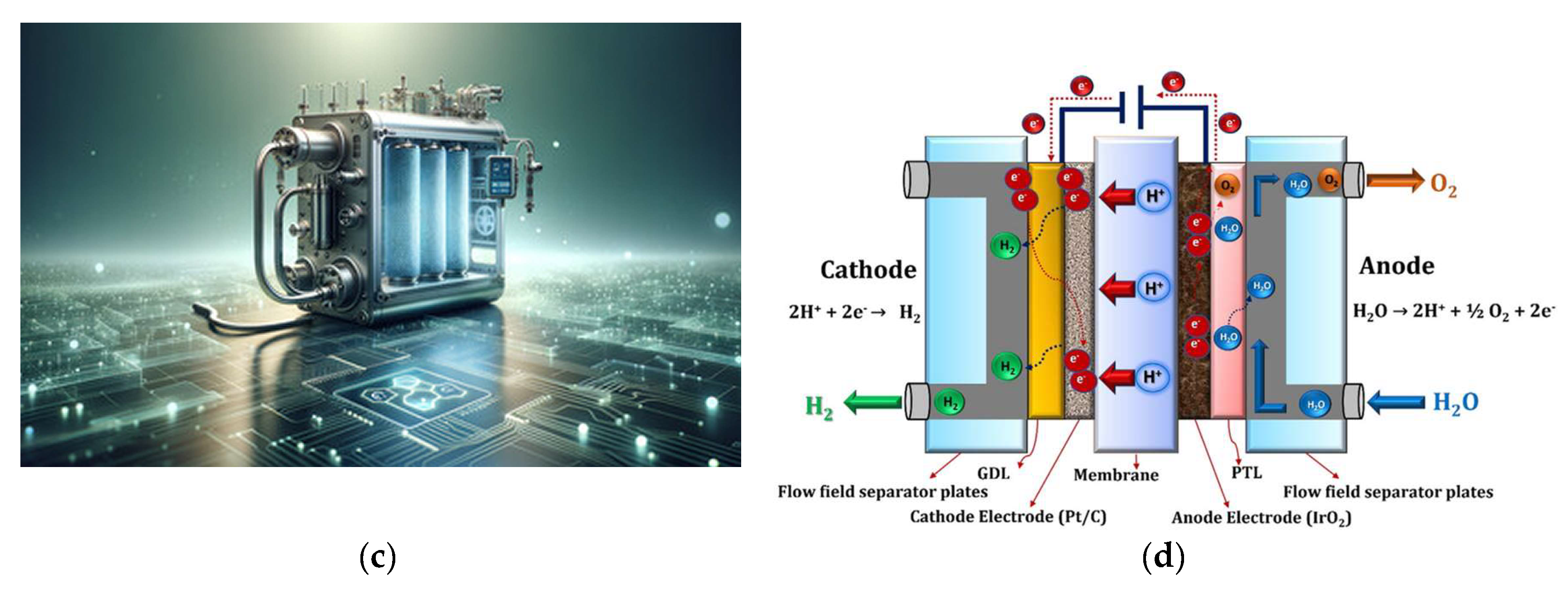
- Minimalist and Photorealistic Image of a PEM Fuel Cell, Showcasing Technological Sophistication and Commercial Potential. https://stock.adobe.com/pl/search?get_facets=1&order=relevance&safe_search=1&search_page=1&k=PEM+fuel+cell&filters%5Bcontent_type%3Aphoto%5D=1&filters%5Bcontent_type%3Azip_vector%5D=1&clickref=1101lyKmtyqm&mv=affiliate&mv2=Freepik&as_camptype=&as_channel=affiliate&as_source=partnerize&as_campaign=Freepik&as_content=api&as_audience=srp&sdid=6WTV6YJ5&asset_id=727872286. (accessed on 6 July 2024).
- Afroze, S.; Sofri, A.N.S.B.; Reza, M.S.; Iskakova, Z.B.; Kabyshev, A.; Kuterbekov, K.A.; Bekmyrza, K.Z.; Taimuratova, L.; Uddin, M.R.; Azad, A.K. Solar-Powered Water Electrolysis Using Hybrid Solid Oxide Electrolyzer Cell (SOEC) for Green Hydrogen—A Review. Energies 2023, 16, 7794. [Google Scholar] [CrossRef]
- Vidas, L.; Castro, R. Recent Developments on Hydrogen Production Technologies: State-of-the-Art Review with a Focus on Green-Electrolysis. Appl. Sci. 2021, 11, 11363. [Google Scholar] [CrossRef]
- Srinivas, S.; Dhanushkodi, S.R.; Chidambaram, R.K.; Skrzyniowska, D.; Korzen, A.; Taler, J. Benchmarking Electrolytes for the Solid Oxide Electrolyzer Using a Finite Element Model. Energies 2023, 16, 6419. [Google Scholar] [CrossRef]
- Léon, A.; Micero, A.; Ludwig, B.; Brisse, A. Effect of scaling-up on the performance and degradation of long-term operated electrolyte supported solid oxide cell, stack and module in electrolysis mode. J. Power Sources 2021, 510, 230346. [Google Scholar] [CrossRef]
- Wolf, S.E.; Winterhalder, F.E.; Vibhu, V.; de Haart, L.G.J.; Guillon, O.; Eichel, R.-A.; Menzler, N.H. Solid oxide electrolysis cells–current material development and industrial application. J. Mater. Chem. A 2023, 11, 17977–18028. [Google Scholar] [CrossRef]
- Wolf, S.E.; Vibhu, V.; Tröster, E.; Vinke, I.C.; Eichel, R.-A.; de Haart, L.G.J. Steam Electrolysis vs. Co-Electrolysis: Mechanistic Studies of Long-Term Solid Oxide Electrolysis Cells. Energies 2022, 15, 5449. [Google Scholar] [CrossRef]
- Hauch, A.; Blennow, P. Solid oxide electrolysis cells–Interplay between operating conditions, fuel electrode overpotential and degradation. Solid State Ion. 2023, 391, 116127. [Google Scholar] [CrossRef]
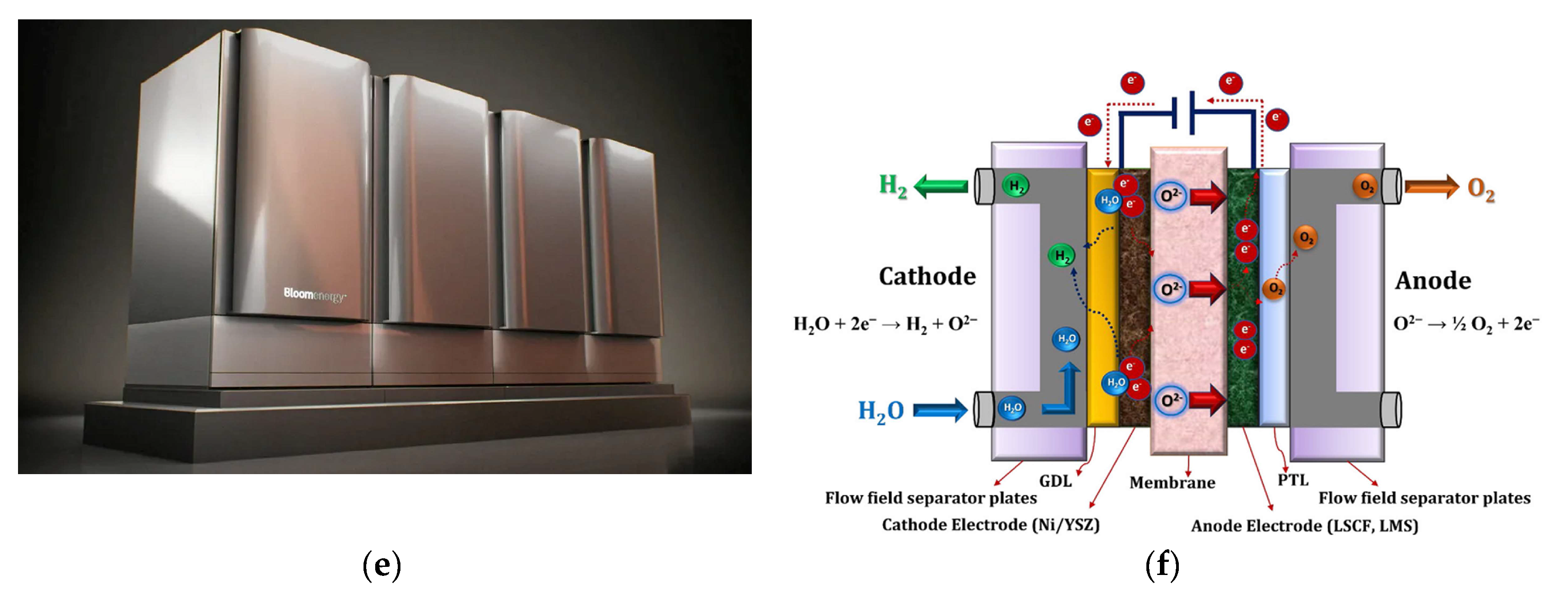
- Hydrogeninsight. Electrolysers. World’s largest solid-oxide hydrogen electrolyser installed at Nasa facility in California. https://www.hydrogeninsight.com/electrolysers/world-s-largest-solid-oxide-hydrogen-electrolyser-installed-at-nasa-facility-in-california/2-1-1445358?zephr_sso_ott=6ovF9u. (accessed on 16 July 2024).
- Liu, L.; Ma, H.; Khan, M.; Hsiao, B.S. Recent Advances and Challenges in Anion Exchange Membranes Development/Application for Water Electrolysis: A Review. Membranes 2024, 14, 85. [Google Scholar] [CrossRef] [PubMed]
- Li, C.; Baek, J.-B. The promise of hydrogen production from alkaline anion exchange membrane electrolyzers. Nano Energy 2021, 87, 106162. [Google Scholar] [CrossRef]
- Li, D.; Motz, A.R.; Bae, C.; Fujimoto, C.; Yang, G.; Zhang, F-Y.; Ayers, K.E.; Kim, Y.S. Durability of anion exchange membrane water electrolyzers. Energy Environ. Sci. 2021, 14, 3393. [Google Scholar] [CrossRef]
- Santoro, C.; Lavacchi, A.; Mustarelli, P.; Di Noto, V.; Elbaz, L.; Dekel, D.R.; Jaouen, F. What is Next in Anion-Exchange Membrane Water Electrolyzers? Bottlenecks, Benefits, and Future. ChemSusChem. 2022, 15, e202200027. [Google Scholar] [CrossRef] [PubMed]
- Miller, H.A.; Bouzek, K.; Hnat, J.; Loos, S.; Bernäcker, C.I.; Weißgärber, T.; Röntzsch, L.; Meier-Haack, J. Green hydrogen from anion exchange membrane water electrolysis: a review of recent developments in critical materials and operating conditions. Sustain. Energy Fuels 2020, 4, 2114. [Google Scholar] [CrossRef]
- Noor Azam, A.M.I.; Ragunathan, T.; Zulkefli, N.N.; Masdar, M.S.; Majlan, E.H.; Mohamad Yunus, R.; Shamsul, N.S.; Husaini, T.; Shaffee, S.N.A. Investigation of Performance of Anion Exchange Membrane (AEM) Electrolysis with Different Operating Conditions. Polymers 2023, 15, 1301. [Google Scholar] [CrossRef] [PubMed]
- Du, N.; Roy, C.; Peach, R.; Turnbull, M.; Thiele, S.; Bock, C. Anion-Exchange Membrane Water Electrolyzers. Chem. Rev. 2022, 122, 11830–11895. [Google Scholar] [CrossRef]
- Enapter. AEM Flex 120: The electrolyser fitting your production needs. https://www.enapter.com/aem-electrolysers/aem-flex-120. (accessed on 17 July 2024).


| Advantage | Grey hydrogen | Green hydrogen |
|---|---|---|
| Environmental benefits |
|
|
| Renewable and sustainable |
|
|
| Energy security |
|
|
| Versatility |
|
|
| Economic opportunities |
|
|
| Health and air quality |
|
|
| Technological innovation |
|
|
| Component | AEs | PEM electrolyzers | AEM electrolyzers | SOEs |
|---|---|---|---|---|
| Electrolyte | KOH 5−7 mol L−1 | PFSA membranes | DVB polymer support with KOH or NaHCO3 1 mol L−1 | Yttria-stabilized Zirconia (YSZ) |
| Separator | ZrO2 stabilized with PPS mesh | Solid electrolyte | Solid electrolyte | Solid electrolyte |
| Electrode/catalyst (oxygen side) |
Nickel coated perforated stainless steel |
Iridium oxide | High surface area Ni or NiFeCo alloys |
Perovskite-type (e.g., LSCF, LSM) |
| Electrode/catalyst (hydrogen side) |
Nickel coated perforated stainless steel |
Platinum nanoparticles on carbon black |
High surface area Nickel |
Ni/YSZ |
| Porous transport layer Anode |
Nickel mesh (not always present) |
Platinum coated sintered porous titanium |
Nickel foam | Coarse Nickel-mesh or foam |
| Porous transport layer Cathode | Nickel mesh | Sintered porous titanium or carbon cloth |
Nickel foam or carbon cloth | None |
| Bipolar plate anode | Nickel-coated stainless steel | Platinum-coated Titanium |
Nickel-coated stainless steel | None |
| Bipolar plate cathode | Nickel-coated stainless steel | Gold-coated titanium | Nickel-coated stainless steel | Cobalt-coated stainless steel |
| Frames and sealing | PSU, PTFE, EPDM | PTFE, PSU, ETFE | PTFE, Silicon | Ceramic glass |
| Parameter | 2020 | Target 2050 | R&D focus |
|---|---|---|---|
| Nominal current density | 0.2−0.8 A cm−2 | > 2 A cm−2 | Diaphragm |
| Voltage range (limits) | 1.4−3 V | < 1.7 V | Catalysts |
| Operating temperature | 70−90 °C | > 90 °C | Diaphragm, frames, balance of plant components |
| Cell pressure | < 30 bar | > 70 bar | Diaphragm, cell, frames |
| Load range | 15−100 % | 5−300 % | Diaphragm |
| Hydrogen purity | 99.9−99.9998 % | > 99.9999 % | Diaphragm |
| Voltage efficiency (LHV) | 50−68 % | > 70 % | Catalysts, temperature |
| Electrical efficiency (stack) | 47−66 kWh kg−1 H2 | < 42 kWh kg−1 H2 | Diaphragm, catalysts |
| Electrical efficiency (system) | 50−78 kWh kg−1 H2 | < 45 kWh kg−1 H2 | Balance of plant |
| Lifetime (stack) | 60,000 hours | 100,000 hours | Electrodes |
| Stack unit size | 1 MW | 10 MW | Electrodes |
| Electrode area | 10,000−30,000 cm2 | 30,000 cm2 | Electrodes |
| Cold start (to nominal load) | < 50 minutes | < 30 minutes | Insulation (design) |
| Capital costs (stack) minimum 1 MW |
USD 270/kW | < USD 100/kW | Electrodes |
| Capital costs (system) minimum 10 MW |
USD 500−1000/kW | < USD 200/kW | Balance of plant |
| Parameter | 2020 | Target 2050 | R&D focus |
|---|---|---|---|
| Nominal current density | 1−2 A cm−2 | 4−6 A cm−2 | Design, membrane |
| Voltage range (limits) | 1.4−2.5 V | < 1.7 V | Catalyst, membrane |
| Operating temperature | 50−80 °C | 80 °C | Effect on durability |
| Cell pressure | < 30 bar | > 70 bar | Membrane, reconversion catalysts |
| Load range | 5−120 % | 5−300 % | Membrane |
| Hydrogen purity | 99.9−99.9999 % | Same | Membrane |
| Voltage efficiency (LHV) | 50−68 % | > 80 % | Catalysts |
| Electrical efficiency (stack) | 47−66 kWh kg−1 H2 | < 42 kWh kg−1 H2 | Catalysts/membrane |
| Electrical efficiency (system) | 50−83 kWh kg−1 H2 | < 45 kWh kg−1 H2 | Balance of plant |
| Lifetime (stack) | 50,000−80,000 hours | 100,000−120,000 hours | Membrane, catalysts, PTLs |
| Stack unit size | 1 MW | 10 MW | MEA, PTL |
| Electrode area | 1500 cm2 | > 10,000 cm2 | MEA, PTL |
| Cold start (to nominal load) | < 20 minutes | < 5 minutes | Insulation (design) |
| Capital costs (stack) minimum 1 MW |
USD 400/kW | < USD 100/kW | MEA, PTLs, BPs |
| Capital costs (system) minimum 10 MW |
USD 700−1400/kW | < USD 200/kW | Rectifier, water purification |
| Parameter | 2020 | Target 2050 | R&D focus |
|---|---|---|---|
| Nominal current density | 0.3−1 A cm−2 | > 2 cm−2 | Electrolyte, electrodes |
| Voltage range (limits) | 1.0−1.5 V | < 1.48 V | Catalysts |
| Operating temperature | 700−850 °C | < 600 °C | Electrolyte |
| Cell pressure | 1 bar | > 20 bar | Electrolyte, electrodes |
| Load range | 30−125 % | 0−200 % | Electrolyte, electrodes |
| Hydrogen purity | 99.9 % | > 99.9999 % | Electrolyte, electrodes |
| Voltage efficiency (LHV) | 75−85 % | > 85 % | Catalysts |
| Electrical efficiency (stack) | 35−50 kWh kg−1 H2 | < 35 kWh kg−1 H2 | Electrolyte, electrodes |
| Electrical efficiency (system) | 40−50 kWh kg−1 H2 | < 40 kWh kg−1 H2 | Balance of plant |
| Lifetime (stack) | < 20,000 hours | 80,000 hours | All |
| Stack unit size | 5 kW | 200 kW | All |
| Electrode area | 200 cm2 | 500 cm2 | All |
| Cold start (to nominal load) | > 600 minutes | < 300 minutes | Insulation (design) |
| Capital costs (stack) minimum 1 MW |
> USD 2000/kW | < USD 200/kW | Electrolyte, electrodes |
| Capital costs (system) minimum 10 MW |
Unknown | < USD 300/kW | All |
| Parameter | 2020 | Target 2050 | R&D focus |
|---|---|---|---|
| Nominal current density | 0.2−2 A cm−2 | > 2 A cm−2 | Membrane, reconversion |
| Voltage range (limits) | 1.4−2.0 V | < 2 V | Catalyst |
| Operating temperature | 40−60 °C | 80 °C | Effect on durability |
| Cell pressure | < 35 bar | > 70 bar | Membrane |
| Load range | 5−100 % | 5−200 % | Membrane |
| Hydrogen purity | 99.9−99.999 % | > 99.9999 % | Membrane |
| Voltage efficiency (LHV) | 52−67 % | > 75 % | Catalysts |
| Electrical efficiency (stack) | 51.5−66 kWh kg−1 H2 | < 42 kWh kg−1 H2 | Catalysts/membrane |
| Electrical efficiency (system) | 57−69 kWh kg−1 H2 | < 45 kWh kg−1 H2 | Balance of plant |
| Lifetime (stack) | > 5000 hours | 100,000 hours | Membrane, electrodes |
| Stack unit size | 2.5 kW | 2 MW | MEA |
| Electrode area | < 300 cm2 | 1000 cm2 | MEA |
| Cold start (to nominal load) | < 20 minutes | < 5 minutes | Insulation (design) |
| Capital costs (stack) minimum 1 MW |
Unknown | < USD 100/kW | MEA |
| Capital costs (system) minimum 10 MW |
Unknown | < USD 200/kW | Rectifier |
Disclaimer/Publisher’s Note: The statements, opinions and data contained in all publications are solely those of the individual author(s) and contributor(s) and not of MDPI and/or the editor(s). MDPI and/or the editor(s) disclaim responsibility for any injury to people or property resulting from any ideas, methods, instructions or products referred to in the content. |
© 2024 by the authors. Licensee MDPI, Basel, Switzerland. This article is an open access article distributed under the terms and conditions of the Creative Commons Attribution (CC BY) license (http://creativecommons.org/licenses/by/4.0/).


