1. Introduction
The ability to perform transient maneuvers at low speeds and high angle of attack (AOA) is an important advantage in air combat [
1,
2,
3]. However, for an aircraft that does not have the maneuverability in the post-stall region, once it approaches the stall AOA, the flow over the airfoil separates and the performance of the aerodynamic control surfaces drops sharply. On the other hand, the nonlinear effect induced by the inertial coupling moment [
4,
5,
6] is particularly significant at high AOA. The first problem has been solved by using thrust vectoring control (TVC) to compensate the loss of aerodynamic control at high AOA [
7,
8]. The use of TVC technology can enhance the maneuverability and stability of the aircraft in stall conditions [
2,
9,
10,
11], and help increase the maneuverability of close air combat [
12]. In addition, TVC can reduce the use of traditional control surfaces, such as horizontal tails and vertical tails, and realize the design of tailless aircraft [
13,
14].
The second problem raised by high AOA flight is the nonlinear effects, which bring great difficulties to the design of linear flight control. Linear controllers designed for a certain trim condition are often insufficient to handle a wider range of flight operations. Although with the help of robust controllers and gain scheduling controllers, the uncertain dynamics caused by nonlinear effects inevitably degrade the performance of linear flight control laws [
15,
16]. Besides linear control approaches, nonlinear control technologies have been developed in recent decades to design flight control systems, such as feedback linearization [
17], backstepping control [
18], sliding mode control [
19], and nonlinear adaptive control [
20]. Among them, nonlinear dynamic inversion (NDI) is one of the most widely used nonlinear control methods [
21], especially in military applications. For example, the development of X-35, the predecessor of F-35, used NDI control law [
22]. The main advantage of the NDI control method is that it can handle a wide range of flight operations, such as flying at high AOA [
23,
24], and directly incorporate nonlinear dynamics into the design of the controller [
25,
26]. In addition, NDI control can be applied to different aircraft, which can reduce the development time and cost of the control system.
The NDI control is a model-based control design, which employs an input-affine nonlinear model to describe the flight motion involving large attitude maneuvers and small control surface deflections by retaining the nonlinear characteristics of the flight dynamics, while allowing the control surface deflection to appear linearly in the state equations. A single NDI control law derived from the input-affine nonlinear model can cover the entire flight envelope without the need for gain scheduling. However, the existence of an exact NDI controller has its prerequisite that the number of control surfaces must be greater than the total number of state variables. To solve the problem of insufficient number of control surfaces, this paper divides the nine state variables into three loops based on their different time scales so that the angular-rate states constitute the inner loop, the attitude states constitute the outer loop, and the flight-path states constitute the outermost loop. Since a loop only involves three state variables, the corresponding NDI controller for each loop can be realized exactly by using three control inputs to achieve the goal of perfect tracking.
The proposed NDI flight control is validated numerically for an experimental F-16 installed with TVC in the post-stall flight. Since the existing F-16 only has aerodynamic control surfaces, when the AOA exceeds 35 degrees, it enters the post-stall region and loses its flight maneuverability. Therefore, although there have been many discussions in the literature about applying NDI control to F-16, they are all limited to flights below the stall AOA [
23,
27,
28,
29]. Here, we retain all the original design of the F-16 (including the engine), except for replacing its fixed nozzle by a thrust vectoring nozzle. What we want to test is whether the experimental F-16 can fly with high maneuverability in the post-stall region when the total thrust remains unchanged and only the direction of the thrust can be changed. The numerical simulations verify that the experimental F-16 under the NDI control can effectively track high AOA command for post-stall flight and successfully demonstrate the Herbst maneuver by performing the heading reversal with
AOA.
To facilitate high AOA turns, we first establish the equations of flight motion based on the wind-axis coordinates in
Section 2. The obtained equations are further rewritten into an input-affine nonlinear form in
Section 3 and separated into a three-layer loop structure to facilitate the independent design of the NDI controller for each layer.
Section 4 designs the NDI controller for the angular-rate inner loop. The purpose is to determine the deflection angle of the control surfaces so that the aircraft's angular rate can track the command given by the outer loop.
Section 5 designs the NDI controller for the attitude outer loop, whose purpose is to determine the angular-rate command so that the aircraft’s attitude tracks the command given by the outermost loop. In
Section 6, the NDI controller developed previously is applied to an experimental F-16 to verify its high-AOA maneuverability in the post-stall region. The conclusion section discusses the modeling errors that may be induced by the input-affine nonlinear model with separable loop structure and proposes quantitative index for measuring the error and feasible methods to reduce the error.
2. Equations of Motion in Wind-Axis Coordinates
Many post-stall maneuvers require the aircraft to roll around the wind axis rather than the body axis. This is because when the aircraft rolls around the body axis, it will cause the interchange between the AOA
and the angle of sideslip
, as shown in
Figure 1, where we can see that when the aircraft rotates 90 degrees around its body axis, the aircraft's AOA changes to the sideslip angle, and vice versa. This interchange between
and
does not cause problem at small AOA, but at high AOA it would be unacceptable because the induced large sideslip angle would greatly degrade the rolling performance of the aircraft. To eliminate the kinematic coupling between
and
, an aircraft operating at high AOA is usually designed to roll around the wind axis and its flight motion is better described by the wind-axis coordinates than the body-axis coordinates.
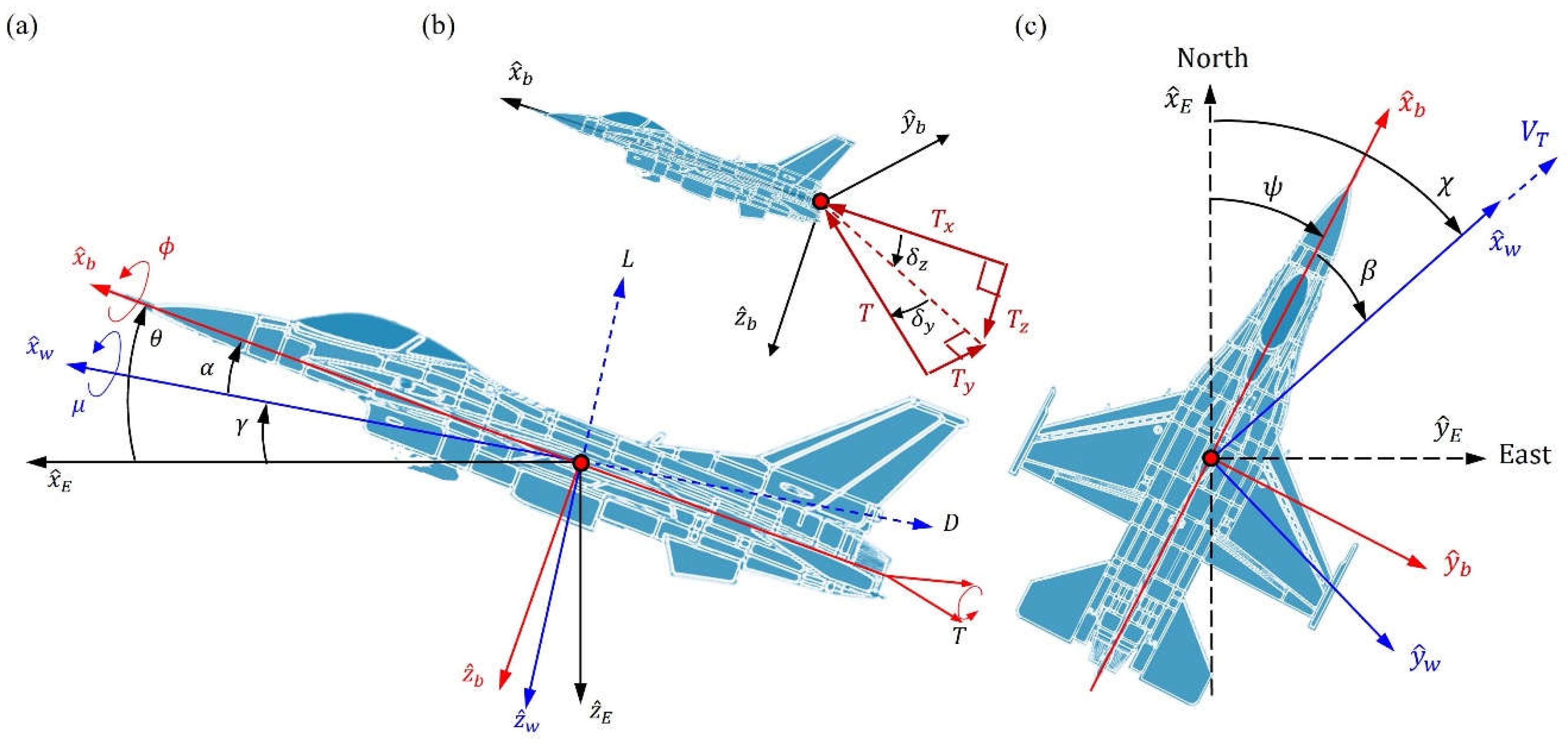
To describe the attitude of the body-axis frame relative to the local horizontal frame, it is common to employ three Euler angles with being the rolling angle around the body axis. Instead of three Euler angles, here we use five angles to describe the aircraft’s attitude, namely AOA , sideslip angle , bank angle (rotation angle around the wind axis), flight path angle and heading angle , of which the first three are used to represent the attitude of the aircraft’s body axis relative to the wind axis and the last two represent the attitude of the wind axis relative to the local horizontal coordinates.
The relative orientation between the three coordinate systems is illustrated in
Figure 2. The origin of the local horizontal coordinates
is located on the earth's surface (ignoring the earth's rotation), where the
axis points to the local north, the
axis points to the local east, and the
axis points to the center of the earth. The origin of the body-axis coordinates
is located at the center of mass of the aircraft, where the
axis points to the direction of the nose along the symmetry line of the aircraft, the
axis is perpendicular to
and points to the right direction of the aircraft, and the
axis points in the direction of
.
The wind axis
points to the velocity direction of the aircraft, so the aircraft’s velocity can be expressed as
, where
is the magnitude of the velocity and the velocity direction
relative to the local horizontal coordinates is defined by
, where
is the flight path angle between the wind axis
and the local horizontal plane (see
Figure 2a), and
is the heading angle between the projection of the wind axis on the local horizontal plane and the local north
(see
Figure 2c). By rotating an angle χ on the local horizontal plane, and then rotating an angle
on the vertical plane, we can transfer the local horizontal coordinates
to the wind axis coordinates
, as expressed by Eq. (A.1). The change rate of the flight-path states
satisfies the following equations (referring to
Appendix A for the derivation):
The lift
, the drag
, and the lateral force
are defined on the wind-axis coordinates and are related to the force components
based on the body axis via the following relation,
where
is the dynamic pressure,
is the area of the main wing,
is the atmospheric density, and
,
,
are the aerodynamic force coefficients of the three directions of the aircraft body axis, which can be read from the aero data tables of F-16 according to the deflection angles of the elevator
, the aileron
, and the rudder
(see
Appendix A for details). The aero data tables are based on the wind tunnel test results of F-16 at NASA Langley and Ames Research center. The database is valid for
,
and
, which covers the post-stall flight region considered here.
The thrust components
in Eq. (1) – Eq. (3) are generated by the thrust vectoring nozzle:
where
is the total thrust of the aircraft,
is the left-right deflection angle of the nozzle (defining it as positive to the left), and
is the up-down deflection angle of the nozzle (defining downward deflection as positive), as shown by
Figure 2b. When the thrust vector deflects to the left, a rightward thrust
will be generated along the positive
direction of the body axis. When the nozzle deflects downward, an upward thrust
will be generated along the negative
, yielding a negative sign of
.
The wind-axis frame is an intermediate frame between the local horizontal frame and the aircraft body-axis frame. By a sequence of rotations,
as shown by Eq. (A2), the wind-axis coordinates
can be transferred into the body-axis coordinates
. The governing equations for
can be established as follows (see
Appendix A for the derivation):
It can be seen above that the attitude change rates
depend on the body-axis angular rates
, which in turn depend on the external moments
as
where the constants
are defined by the given moments of inertia of F-16 (see
Appendix A). The external moment
experienced by the aircraft is composed of the aerodynamic moment
and the thrust moment
. The aerodynamic moment
is determined by the aerodynamic coefficients:
where
is the span of the main wing,
is the average chord length, and
,
, and
are the aerodynamic moment coefficients in the three directions of the aircraft body axis. The thrust moment
is produced by the thrust about the center of gravity of the aircraft and can be expressed as
where
is the distance from the center of gravity to the nozzle, and
and
are given by Eq. (5).
The flight motion under the wind-axis coordinates is described by nine states, for which the flight-path states
are given by Eq. (1) – Eq. (3), the attitude states
are given by Eq. (6) – Eq. (8), and the angular-rate state
are given by Eq. (9) – Eq. (11). As shown in
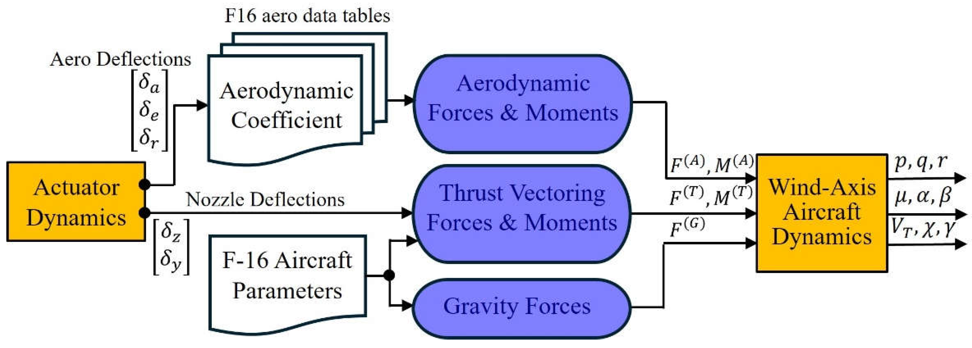
Figure 3, The output of the nine states is governed by the five control inputs
, which generate the aerodynamic force
by Eq. (4), the aerodynamic moment
by Eq. (12), the thrust force
by Eq. (5), and the thrust moment
by Eq. (13). By solving the nine equations of motion subjected to the applied forces and moments, we obtain the position, velocity and attitude of the aircraft relative to the local horizontal coordinates at any instant
. Compared with the body-axis based state variables
, the wind-axis based state variables
are more suitable for designing flight control law of aircraft maneuvering at high AOA.
3. NDI Flight Control Law Design
The equations of motion of the nine states
derived previously can be expressed as an input-affine nonlinear form:
where
is the vector function with 9 elements and
is the matrix function with dimension
, and
is the system’s output vector. The control input
consists of the aerodynamic deflection angles
and the nozzle deflection angles
. Due to the limitations of the practical deflection mechanism, the deflection angle of each control surface is small so that the aerodynamic/thrust force and moment can all be expanded as a linear function of
; however, the small angle assumption is not valid for the state
. This situation is reflected in the input-affine nonlinear form (14), where the nonlinear nature of the state
is retained, while the control input
appears linearly.
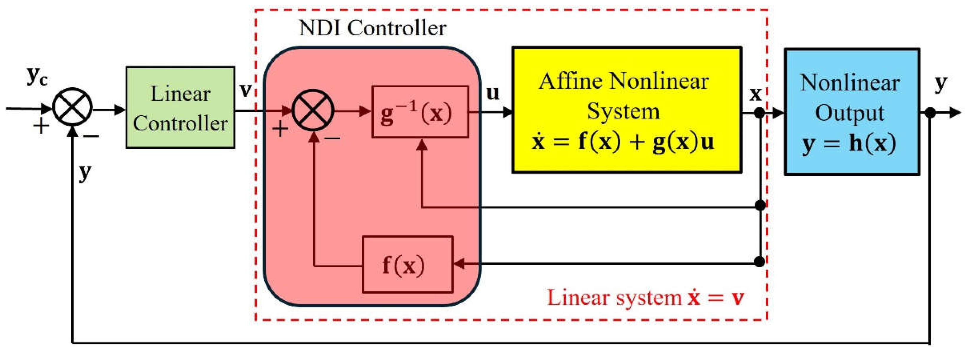
The NDI control architecture is shown in
Figure 4. The essence of the NDI control design is to determine the control signal
through the dynamic inverse process to transform the nonlinear system into an equivalent linear system. After the process of feedback linearization, an auxiliary linear controller is then designed to reduce the tracking error between the output
and the command
.
The control input
that linearizes the nonlinear system (14) can be found as,
If this control is used in Eq. (14), we obtain the desired result:
Accordingly, the effect of the NDI control amounts to making the inner closed-loop system behave like a linear system as shown by
Figure 4. After the feedback linearization is achieved, the new control input
can then be designed by any linear control method to drive the system output
to follow the target output
.
The existence of the ideal NDI controller (15) depends on the invertibility of the matrix function
. Unfortunately, the inverse of the matrix
with dimension
considered here does not exist. The mathematical reason is that the number of its rows (number of equations) is greater than the number of its columns (number of unknowns), and the physical reason is that there are 9 desired states in Eq. (14) to be tracked, but only 5 degrees of freedom of control are available. Apparently, the desired state rate
can only be tracked partially and the best control we can design is to minimize the tracking error by replacing the inverse
in Eq. (15) with its pseudo inverse,
where
is the solution minimizing the distance
, where
is the
identity matrix.
For flight control applications, the pseudo-inverse approach is not the only way to solve the NDI control problem. Although the mathematical relationship in Eq. (14) indicates that the control affects the 9 states simultaneously, the degree of influence on each state is very different. Due to the inherent dynamic characteristics of the aircraft, the first response to the change in the control surface deflections is the aircraft's body-axis angular rates . When the aircraft’s angular rate changes, its attitude will change accordingly. The heading angle and flight path angle of the aircraft will not respond until the attitude of the aircraft changes. The sequence of response is that the control affects first, then affects , and finally affects . Therefore, the response speed of the 9 states to the control is that the angular-rate state has the fastest response, the attitude state is slower, and the flight-path state is the slowest.
The concept of NDI design reverses the above sequence of dynamic response. It starts from the desired flight-path state to find reversely the required attitude state , from the desired attitude state to find reversely the required angular-rate state , and finally from the desired angular-rate state to find reversely the required control surface deflection .
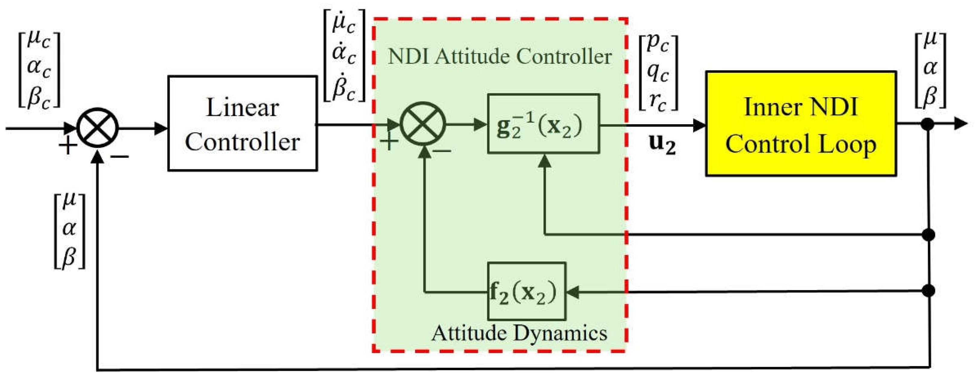
Based on the fact that the three sets of states have three different time scales, the entire flight control loop can be separated into three layers of loop, as shown in
Figure 5, where the inner loop is the angular-rate control loop regarding the control of the fast states
, the outer loop is the attitude control loop regarding the control of the slow states
, and the outermost loop is the flight-path control loop regarding the control of the slowest state
. The current article focuses on the NDI control design for the inner loop and the outer loop.
Since the nine states are in three different loops according to the difference in their time scales, independent NDI controller can be designed for each loop, which handles only part of the nine states and makes the pseudo-inverse operation unnecessary. In the inner loop of
Figure 5, only three angular-rate states
are concerned and the inner NDI control problem is to find reversely the control surface deflection
to achieve the desired angular-rate response
. Similarly, in the outer loop of
Figure 5, only three attitude states
are concerned and the outer NDI control problem is to find reversely the required angular-rate input
to achieve the desired attitude response
.
4. Angular-Rate NDI Control
The NDI control design in the inner loop is to determine the control surface deflection
so that the response of aircraft’s angular rates
follows the command
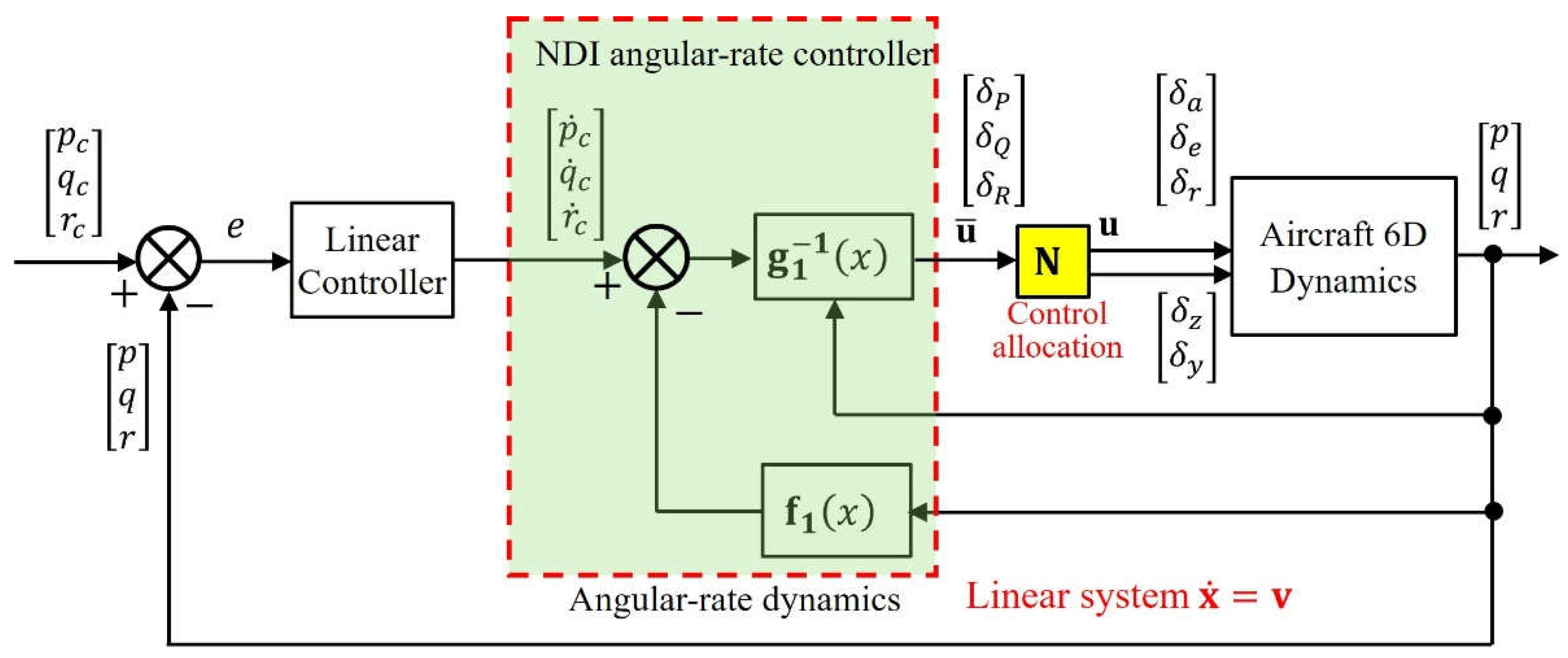
, as shown in
Figure 6.
To design the inner-loop NDI controller
, the fully nonlinear equations (9) – (11) must be transformed into an affine nonlinear form, wherein the control input
appears linearly. The main task involved in this transformation is to expand the aerodynamic/thrust moments in Eq. (9) – Eq. (11) as a linear function of
, which yields the following affine nonlinear form:
where explicit expressions for the elements in the vector
and the matrix
are given by Eq. (A17) in
Appendix A. Although the three angular rates
are the dominant states in Eq. (18), all the nine states in
are involved in the expressions of
and
; however, as measured under the time scale of
, the remaining six states in
, i.e.,
, can be treated as constants in the inner loop.
The control targets in the inner loop are the three desired angular rates
, but there are 5 independent control inputs
can be manipulated. Consequently, many possible combinations of the five control inputs can be employed to achieve the desired angular rates, and an appropriate control allocation is required to find the best combination. Mathematically, it means that the matrix
in Eq. (18) is (right) invertible, i.e.,
, but its inverse
is not unique. Due to the non-uniqueness of
, all the possible solutions of
can be expressed as
where
is the control allocation matrix, whose elements can be arbitrarily assigned as long as
is nonsingular. The effective control
consists of three effective control surface deflections,
,
, and
, required for controlling the rolling rate
, the pitching rate
, and the yawing
, respectively.
The elements of matrix
indicate how each control surface deflection is allocated to the control of the three angular rates. For example, the first equation in Eq. (19) reads,
which means that
percentage of the total aileron deflection
is allocated to the rolling rate control,
percentage to the pitching rate control, and
percentage to the rolling rate control. It is worth noting that
and
are the deflection angles of the thrust vectoring nozzle and the last two rows of
tell us how the total thrust is allocated to the control of the three angular rates. Regarding the setting of the elements of matrix
, we must also consider the angle and rate limitations of the deflection mechanism imposed on different control surfaces. There are many control allocation methods, which can be used to determine the matrix
, such as daisy chain, explicit ganging, pseudo control or control selector, and pseudo inverse [
30,
31].
The effective control
is to be determined so that the aircraft’s angular acceleration
converges to the command
. The ideal effective control
can be derived by letting
and
in Eq. (18) to obtain
where
is a nonsingular
matrix and its inverse is defined uniquely. With the effective control
given by Eq. (21), the actual control surface deflections
are then determined by passing
via the allocation matrix
as shown in
Figure 6.
With NDI controller
given by Eq. (21), the angular-rate dynamics (18) behaves like a linear system, for which a linear controller is to be designed to drive the output of the inner loop to the desired output
. Referring to
Figure 6, the angular acceleration command
is adjusted by the linear controller to drive the tracking error
to zero. Here a simple PI controller is used to generate the command
according to the tracking error
:
where the desired angular rates
come from the output of the outer loop,
are the actual angular rates measured by the angular-rate sensors,
are the adjustable proportional gains, and
are the adjustable integral gains.
5. Attitude NDI Control
The dominant states in the outer NDI control loop are the slow attitude states
. Under the time scale of the attitude states, the fast angular-rate states
have converged to their steady states
by the inner NDI control, while the change of the flight-path states
in the outermost loop are so slow that they can be considered as constants in the outer loop. As mentioned earlier, the dominant response of the angular-rate dynamics
is caused by the control surface deflections
, while the dominant response of the attitude dynamics
is caused by the angular-rate input
, rather than by the control surface deflections
. With the above understanding, the response of the attitude dynamics to the body-axis angular rates can be derived from Eq. (6) – Eq. (8) by letting
as the steady angular-rate states and ignoring the secondary influences of the control surface deflections
on the attitude states. The result can be expressed as the following affine nonlinear form:
where the reduced state
are defined as
and
is treated as the control input. The three nonlinear functions in Eq. (23) are given by,
In Eq. (23), the angular-rate state
is the control input to the system and the attitude state
is the response to the input. The concept of NDI reverses the sequence of dynamic response by requiring the desired response and reversely finding the necessary input. As shown in
Figure 7, the control input
is to be determined reversely by the NDI design so that the change rate of the attitude state
tracks the desired response
.
By letting
in Eq. (23), the ideal control input
can be determined as
where
is the
nonsingular matrix defined in Eq. (23) and its inverse can be expressed analytically as
Since
is determined uniquely, there is no control allocation problem in the outer NDI loop. After the outer loop is linearized by the NDI controller
, a PI controller is incorporated into the outer loop to attain the desired aircraft’s attitude
according to the attitude tracking error, as shown in
Figure 7. Like the inner-loop PI structure in Eq. (22), proportional gains
and integral gains
are used in the outer-loop attitude controller as follows:
where
are the desired attitudes and
are the aircraft’s actual attitudes provided by the attitude sensors. The magnitude of the proportional gains
reflects the bandwidth of the attitude control in the outer loop and is much smaller than proportional gains
, which reflects the bandwidth of the angular-rate control in the inner loop.
6. Verification of NDI Control for an Experimental F-16 in Post-Stall Flight
The experimental F-16 retains all the original design of the existing F-16 (including the engine), except for replacing its fixed nozzle by a thrust vectoring nozzle. The affine nonlinear model (14) can be used to describe the nonlinear dynamics of the experimental F-16 at high angles of attack by noting that the small angular changes in the thrust direction of the experimental F-16 (within a range of degrees) meet the basic assumption of the affine nonlinear model within which the control input must appear linearly.
The flight performance of the experimental F-16 with and without TVC can be compared easily in the framework of NDI control by using two different control allocation matrices:
Clearly, the main difference in the above two matrices is their last two rows. According to the definition of the allocation matrix in Eq. (19), the last two rows involve the allocation of the and deflections of the thrust to the three body-axis angular rates . The elements in the last two rows of the matrix are all zero, which means that the TVC is not activated, so that the thrust does not contribute to the rotation about the three axes. Matrix corresponds to the situation when TVC is activated, in which the left-right deflection () of the thrust contributes 25% to the rolling rate and 50% to the yawing rate , and the up-down deflection () of the thrust contributes 50% to the pitching rate . The setting of the control allocation matrix is not limited to the form expressed by Eq. (27). We can set different matrix according to different flight mission.
The 6D dynamics of the experimental F-16 is modelled by Eq. (1) – Eq. (3) and Eq. (6) – Eq. (11) with five control inputs and nine state outputs . With the measured state outputs , the control inputs are determined by a sequence of dynamic inverse processes. Here we assume that the attitude command has been designed by an outermost flight-path loop not mentioned here, and we will start with via two dynamic inverse processes to determine the five control surface deflections. At every time step, the 6D simulation contains the following iterative procedures:
Input the current measurement of the nine states .
Compute the current values of and by Eq. (18), and the current values of and by Eq. (23) with the new measurement .
Compute the desired change rate of the attitude by Eq. (26) with given command .
Compute the desired body-axis angular rates by Eq. (24) with given .
Compute the desired angular acceleration by Eq. (22) with given .
Compute the required control surface deflections by Eq. (21) with given and control allocation matrix .
Solve the 6D model with the new control surface deflections for the new value of the states at next time step.
The above iterative procedures are applied to the following three cases of NDI flight simulation to verify the maneuverability of the experimental F-16 in the high AOA region.
6.1. NDI Flight Control of the F-16 without TVC
The first flight simulation is to verify that the traditional F-16 without TVC can fly near its stall AOA under the NDI flight control. The advantage of NDI flight control is that a single NDI controller can cover the entire flight envelope, without the need to divide the flight envelope and linearize the flight dynamics for gain scheduling. The parameters used in the design of NDI control are listed below.
- ●
The thrust setting is with initial speed , initial height , and initial angular rates .
- ●
In the attitude loop, the proportional gains and the integral gains are set to be and .
- ●
In the angular-rate loop, the proportional gains and the integral gains are set to be and .
- ●
The TVC function is deactivated in this case by choosing the control allocation matrix in Eq. (20).
- ●
The sideslip angle command
is set to zero, and the AOA command
and the bank angle command
are given, respectively, as
The attitude command requires the F-16 to maintain level flight for the first 2 seconds, and then in the next 13 seconds, the AOA command
increases linearly from
to the stall angle
and then decreases to
. Meanwhile, the bank angle command
increases linearly from
to
and then decreases to
. The attitude commands are represented by the black curves in
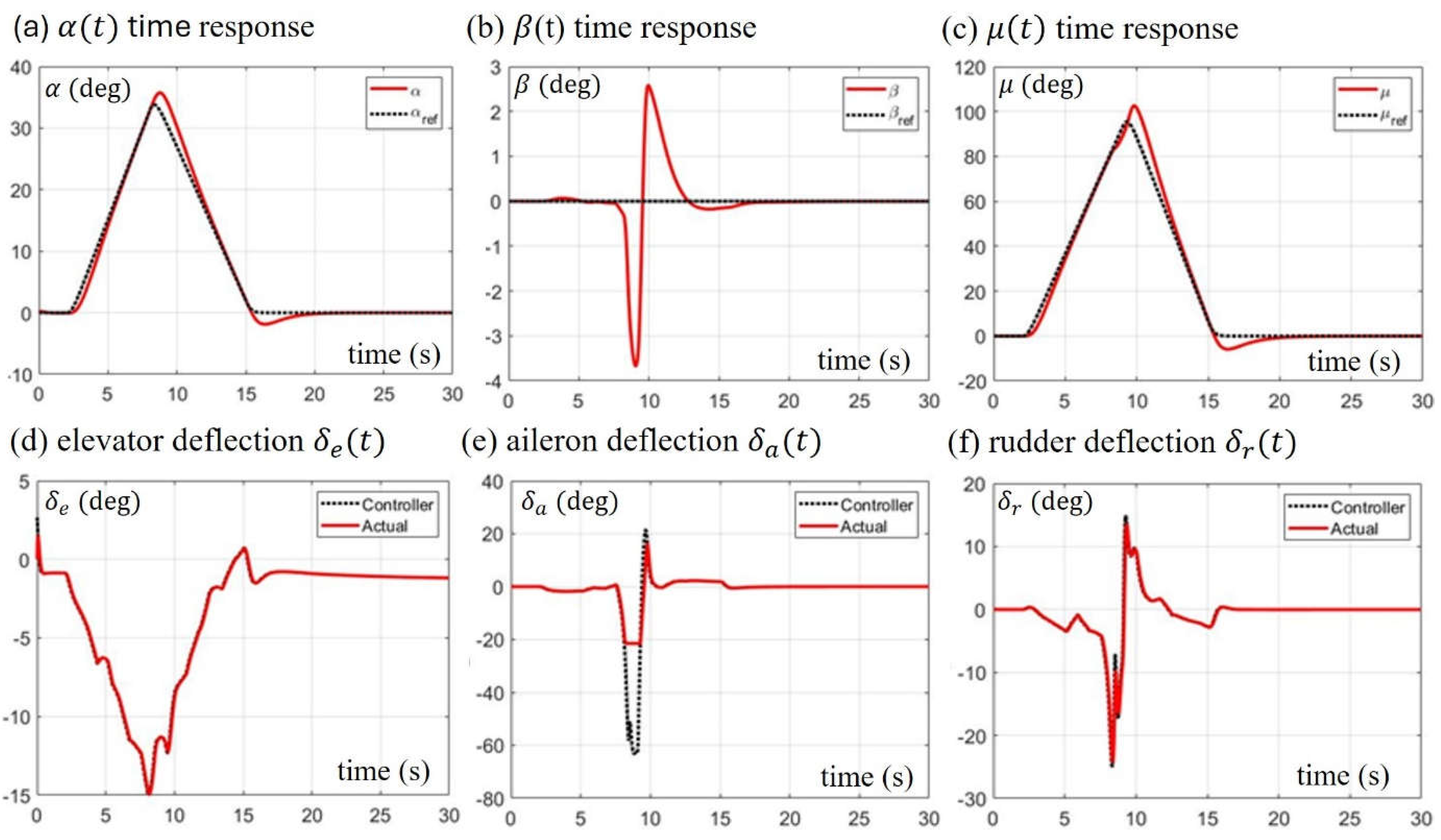
Figure 8a–c, while the actual attitudes of the F-16 under the control of NDI are presented by the red curve. From
Figure 8 we can see that the F-16 flies closely following the attitude commands. The mismatch between the attitude response and the attitude command mainly occurs between
and
, within which the sideslip angle
deviates from zero about 3 degrees, and slight overshoots occur in the response of
and
.
Comparing
Figure 8e, we find that the deviation of the attitudes between
and
is primarily caused by the large aileron deflection angle
required by the NDI controller (black curve), which has far exceeded its saturation angle (
). The flight maneuvers performed by this numerical test are very close to the performance ceiling of the experimental F-16 without TVC. Although it can barely follow the attitude commands to fly, the control surfaces have been deflected to their maximum angles.
6.2. NDI Flight Control beyond Stall AOA with and without TVC
We proceed to test the experimental F-16 to maneuver beyond the stall AOA with and without TVC. To conduct this flight maneuvers, we increase the maximum value of the AOA command in Eq. (28) from
to
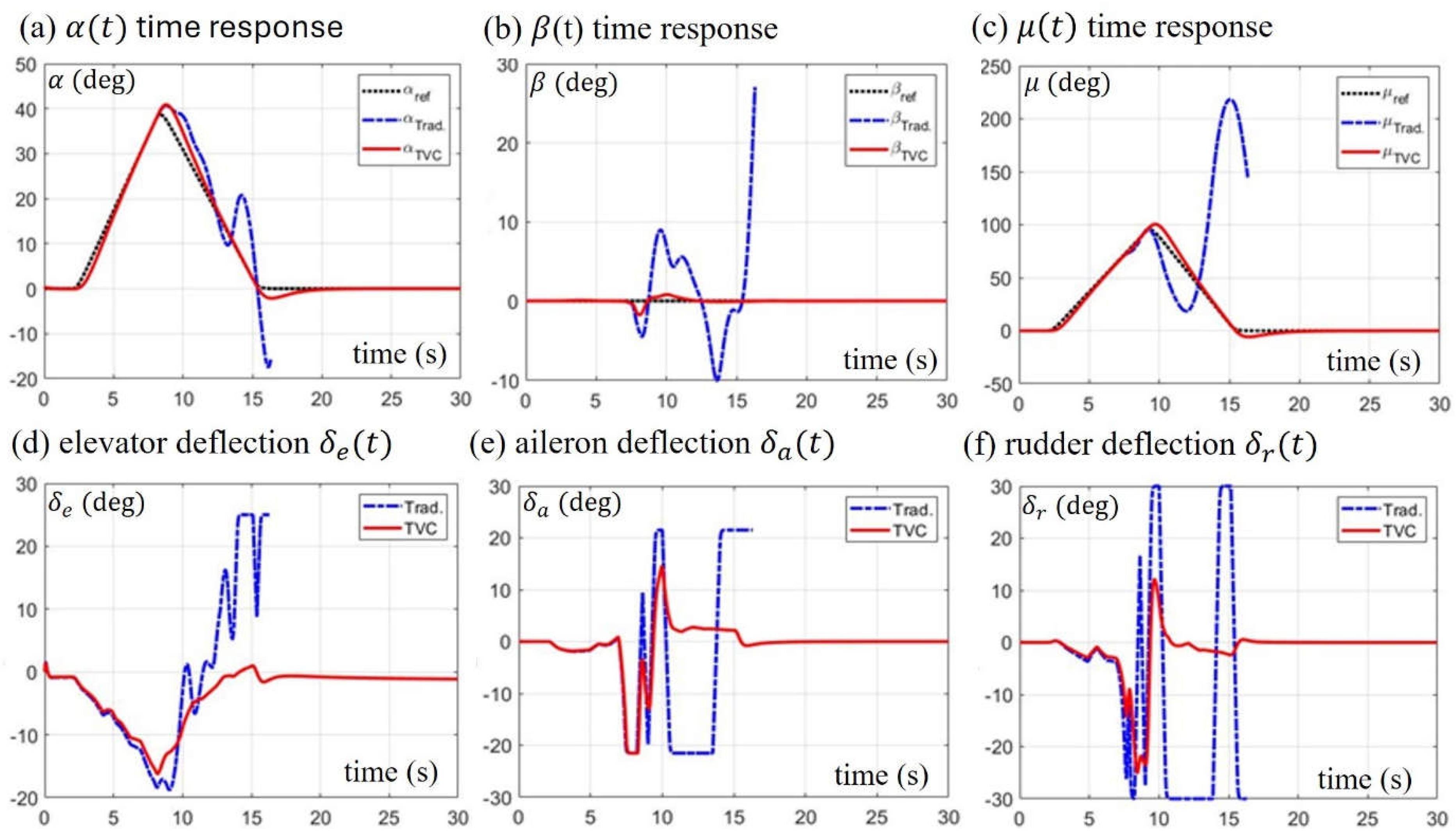
, while other settings remain unchanged. The simulation results are shown in
Figure 9, where the black dotted curve is the input command, the blue chain curve is the aircraft’s response without TVC, and the red curve is the aircraft’s response with TVC. The attitude responses are shown in
Figure 9a–c and the corresponding control surface deflections are shown in
Figure 9d–f.
From the trend of the blue chain curves, we can see that tracking a AOA command exceeds the performance limit of the F-16 without TVC. It appears that the response of the three attitudes began to diverge at , when the F-16 reached its maximum AOA and entered the stall region, causing the aerodynamic surfaces to lose their control force and moment. Meantime, the deflection of the control surfaces was saturated at the maximum angle, indicating that the F-16 had no extra control force to use.
On the other hand, the red solid curves in
Figure 9 show the performance of the experimental F-16 installed with TVC under the NDI control with the control allocation matrix
. From the time responses of the attitude, we can see that the high AOA attitude command is tracked very well with neglectable deviations, and the control surface deflections are safely within their allowable ranges. Through the integration of the aerodynamic control and the thrust control under the NDI framework, thrust control successfully replaces the role of aerodynamic control at high AOA, allowing the experimental F-16 to fly with high maneuverability in the post-stall region.
6.3. Herbst Maneuver with NDI Flight Control
The Herbst maneuver, also known as a J-turn, is an air combat maneuver that uses post-stall technology such as TVC and advanced flight controls to achieve high AOA. The Herbst maneuver allows an aircraft to quickly reverse direction by rolling around the wind axis at high AOA. Apparently, the Herbst maneuver is not demonstrable by the existing F-16. The third numerical verification is to illustrate the Herbst maneuver performed by the experimental F-16 equipped with TVC and NDI control law. The Herbst maneuver is mainly composed of three flight phases:
- ●
Phase 1: The aircraft’s AOA increases to from the level flight to start the heading reversal maneuver.
- ●
Phase 2: The aircraft rotates around the wind-axis at high AOA near to reverse the heading.
- ●
Phase 3: The aircraft stops rotating and lowers its AOA, returning to the level flight.
The typical Herbst maneuver is prescribed by the following attitude commands
[
32]:
and
. Roughly speaking, the period
is the preparation period of the Herbst maneuver, which brings the aircraft to
AOA to start the heading reversal and belongs to phase 1. The period
is the working period of the Herbst maneuver, which performs the heading reversal and belongs to phase 2. The period
is the recovery period from the Herbst maneuver to the level flight, which belongs to phase 3.
The Herbst maneuver performed by the experimental F-16 is simulated by repeating the above seven iterative procedures with given attitude commands
and with thrust setting
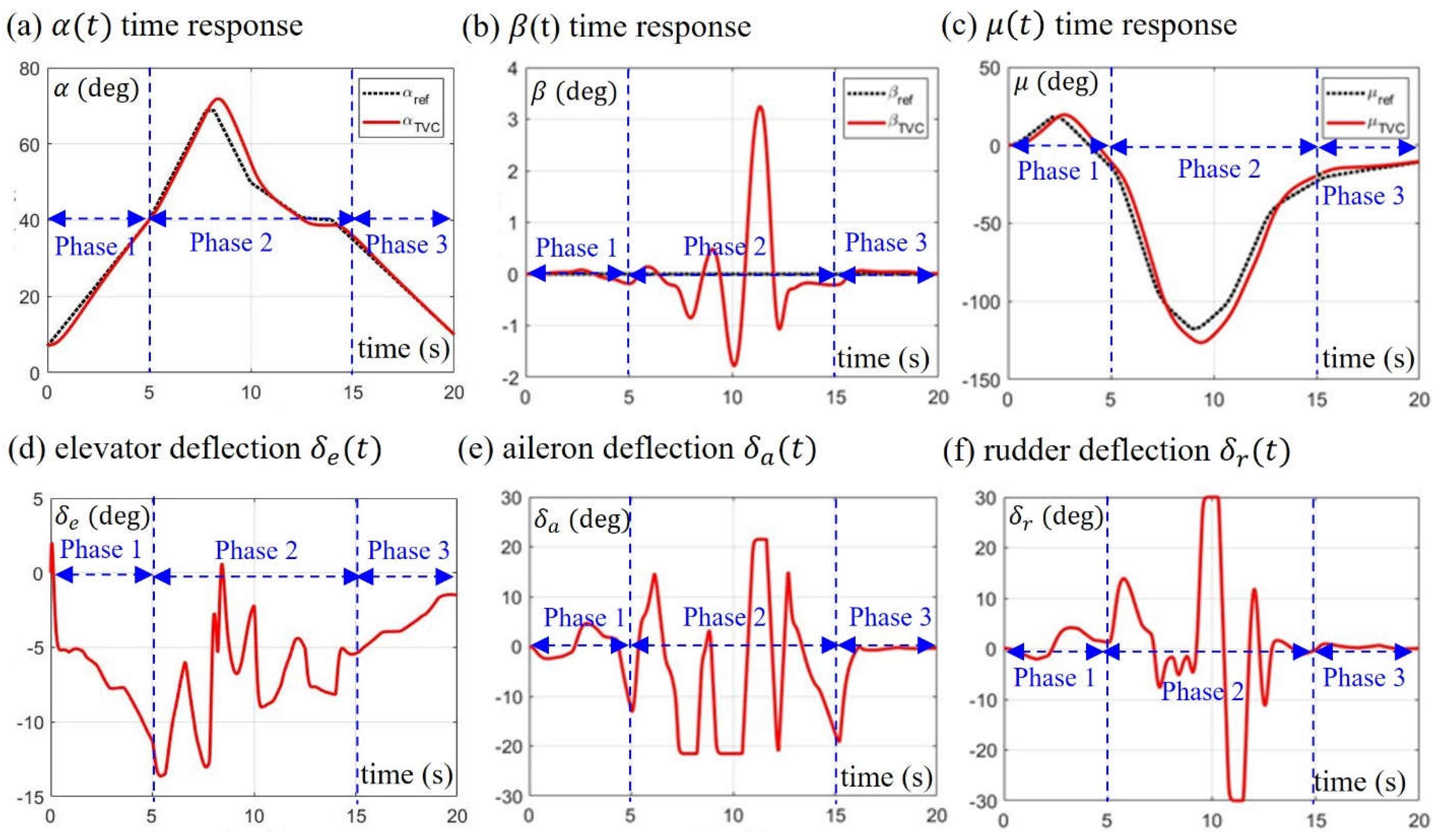
. The response of the experimental F-16 to the commands of the Herbst maneuver is illustrated in
Figure 10 and
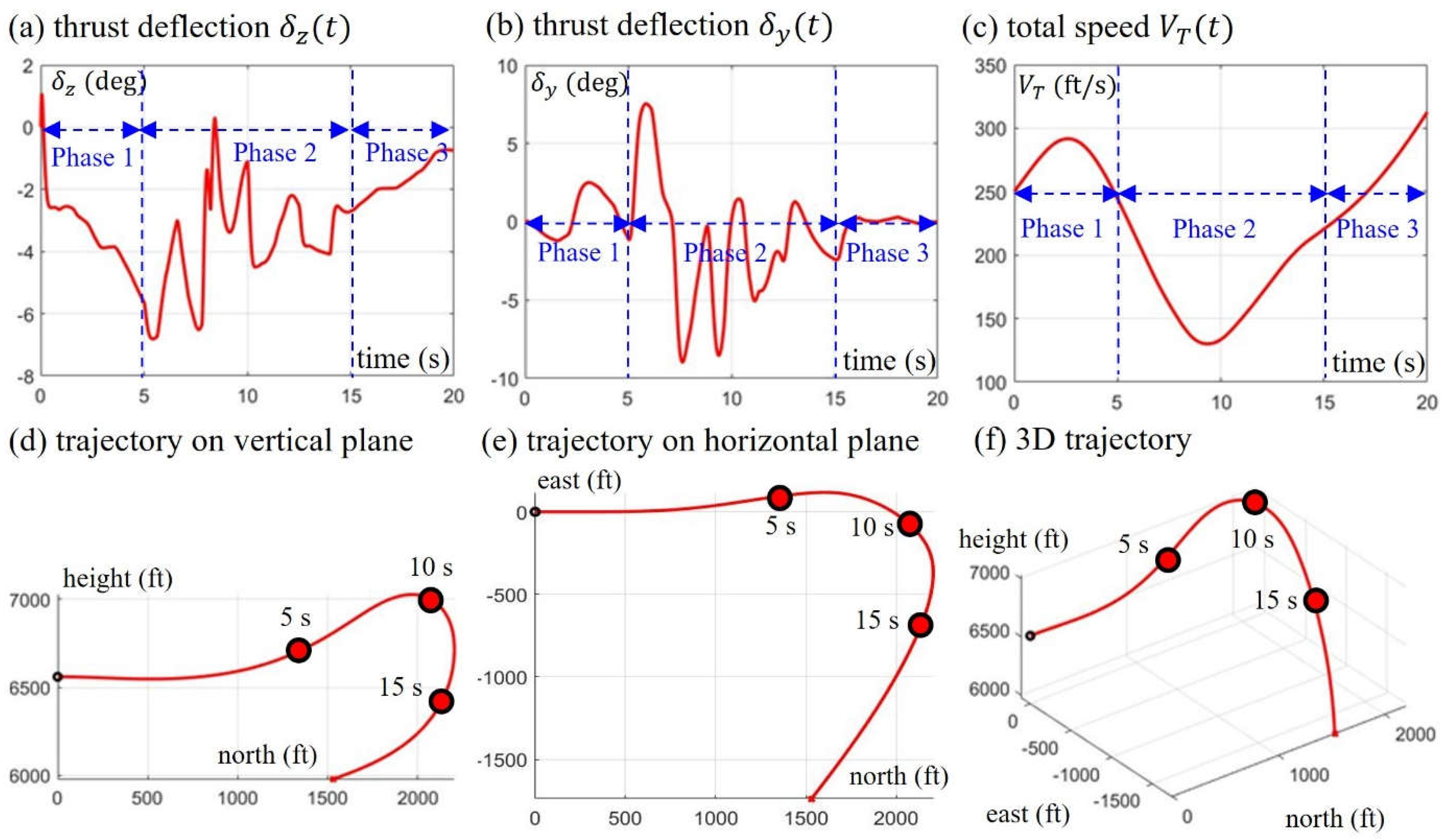
Figure 11. It appears that the flight of the experimental F-16 closely follows the prescribed Herbst maneuver with reasonable tracking errors. As can be seen, in phase 1 and phase 3, the major change in aircraft attitude is AOA due to the elevator deflection
(see
Figure 10d) and the thrust deflection
(see
Figure 11a), while the deflection angles of aileron
and rudder
in phase 1 and phase 3 are relatively small (see
Figure 10e,f). During phase 2, the aircraft rotates around the wind axis by
caused by the significant deflections of
,
, and
; meanwhile, the AOA increases from
to a maximum of
, and then decreases to
.
It is worth noting that during phase 2, the deflection angles of the aileron
and the rudder
has reached their saturation values, and the reason why the aircraft can still complete the heading reversal is mainly due to the deflection of the thrust in the y direction (see
Figure 11b). In addition, in phase 2, we cannot ignore the high aerodynamic drag caused by high AOA. From
Figure 11c, we can see that due to the high drag effect, the aircraft speed profile has an obvious sagging region in phase 2, causing the aircraft speed to drop from 250 ft/s to 130 ft/s, and then gradually rise again.
Figure 11d–f shows the trajectory of the experimental F-16 performing the Herbst maneuver. After the Herbst maneuver is completed, we can see that in the vertical plane, the height of the aircraft drops about 1000ft, while on the horizontal plane, the turning radius of the aircraft is about 2000ft. In addition, we observe from
Figure 11 that the turning point of the Herbst maneuver occurs approximately at
, when the aircraft reaches the highest point, the speed drops to the lowest point, and the bank angle turns to the maximum angle. Overall, the experimental F-16 has accomplished the goal of improving the existing F-16 to a certain extent by proving that the F-16 installed with a thrust vectoring nozzle and controlled by an NDI controller has the maneuverability in the post-stall region.
Figure 1.
The interchange between the AOA and the side slip angle via rolling around the body axis by an angle .
Figure 1.
The interchange between the AOA and the side slip angle via rolling around the body axis by an angle .
Figure 2.
(a, c) The relative orientation between body-axis coordinates , wind-axis coordinates and local horizontal coordinates . (b) Multi-axis thrust vectoring nozzle with deflection along the axis and deflection along the axis.
Figure 2.
(a, c) The relative orientation between body-axis coordinates , wind-axis coordinates and local horizontal coordinates . (b) Multi-axis thrust vectoring nozzle with deflection along the axis and deflection along the axis.
Figure 3.
The computation of forces and moments exerting on the aircraft. The surface deflections generated by the actuators produce the aerodynamic force given by Eq. (4) and moment given by Eq. (12). The thrust deflections produce the thrust force given by Eq. (5) and moment given by Eq. (13). The gravity force is determined by the mass and the attitude of the aircraft.
Figure 4.
Block diagram of the NDI control law design. An ideal NDI controller is expected to make the inner closed-loop system (surrounded by the red dashed box) behave like a linear system .
Figure 4.
Block diagram of the NDI control law design. An ideal NDI controller is expected to make the inner closed-loop system (surrounded by the red dashed box) behave like a linear system .
Figure 5.
The NDI flight control structure can be separated into three layers of loop. The inner loop regards the angular rate control of the fast states , the outer loop regards the attitude control of the slow states , and the outermost loop regards the flight-path control of the slowest states .
Figure 5.
The NDI flight control structure can be separated into three layers of loop. The inner loop regards the angular rate control of the fast states , the outer loop regards the attitude control of the slow states , and the outermost loop regards the flight-path control of the slowest states .
Figure 6.
The inner angular-rate control loop is designed to determine the three aero deflections and two nozzle deflections such that the angular-rate response of the aircraft matches the desired response .
Figure 6.
The inner angular-rate control loop is designed to determine the three aero deflections and two nozzle deflections such that the angular-rate response of the aircraft matches the desired response .
Figure 7.
The outer attitude control loop is designed to generate the angular-rate command
for the inner loop according to the tracking error between the attitude command
and the actual attitude
. The yellow block represents the inner NDI control loop shown in
Figure 6.
Figure 7.
The outer attitude control loop is designed to generate the angular-rate command
for the inner loop according to the tracking error between the attitude command
and the actual attitude
. The yellow block represents the inner NDI control loop shown in
Figure 6.
Figure 8.
The time responses of the attitude and the control surface deflections of the F-16 flying below stall AOA without TVC.
Figure 8.
The time responses of the attitude and the control surface deflections of the F-16 flying below stall AOA without TVC.
Figure 9.
The time responses of attitude and control surface deflections for the experimental F-16 with and without TVC when the AOA command exceeds the stall limit. The black dotted curves are the attitude commands, the blue dash dotted curves denote the responses of the F-16 without TVC, and the red solid curves denote the responses of the F-16 installed with TVC.
Figure 10.
The time responses of the Herbst maneuver for the F-16 installed with TVC and controlled by the NDI controller. The attitude responses show that the F-16 completed the Herbst maneuver in 20 seconds via a rolling angle around the wind axis at , while keeping the side slip angle as small as possible. With the help of TVC, all three aero surfaces operate below their saturation values except for some short periods of time.
Figure 11.
The subgraphs (a) and (b) show the deflection angles of the thrust below their saturation values during the operation of the Herbst maneuver. Subgraph (c) is the total speed profile of F-16 starting from 250 ft/s and accelerating to 300 ft/s to enter the Herbst maneuver, during which the F-16 first decelerates with increasing AOA and reaches its minimum speed of 130 ft/s near to reverse the heading, and then accelerates to recover to the level flight state. Subgraphs (d), (e) and (f) shows the trajectory of the F-16 performing the Herbst maneuver, indicating that the height of the F-16 drops about 1000ft, and the turning radius on the horizontal plane is about 2000ft.

