Preprint
Article

Carbon-based in-situ Ti-TiC Metal Matrix Composite manufactured by Laser Powder Bed Fusion

Altmetrics

Downloads

100

Views

34

Comments

0

Submitted:

06 August 2024

Posted:

07 August 2024

Read the latest preprint version here

Alerts
Abstract
This study outlines a 3-step production process for Ti-TiC Metal Matrix Composite (MMC) employing powder Mechanical Blending, Laser Powder Bed Fusion (LPBF), and a heat treatment. A TiC fraction of more than 20 vol% was formed in-situ through the reaction of titanium with carbon during the LPBF process. The manufactured MMC pieces showed a record stiffness and fracture strain combination. The LPBF energy density impacted strongly porosity type. The as-built microstructure displayed an homogeneous distribution of sub-stoichiometric TiC dendrites which were fully converted into equiaxed TiC grains during the heat treatment. The TiC C/Ti ratio was found to be close to 0.5, resulting in an effective reinforcement content nearly twice the one expected for stoichiometric TiC, leading to stronger reinforcement. The mechanical analysis revealed a Young’s modulus of up to 149 GPa and an ultimate tensile strength of up to 770 MPa, indicating a 27% and 34% improvement, respectively, compared to commercially pure Titanium produced by LPBF and heat treated in the same conditions. A fracture strain of up to 2.8% was achieved. The combination of in-situ formation of defect-free TiC reinforcement and subsequent heat treatment enables to reach an exceptional ductility, considering the 20 vol% reinforcement content.
Keywords: 
Subject: Chemistry and Materials Science  -   Ceramics and Composites

Introduction

Laser Powder Bed Fusion (LPBF) since its inception has been used to further improve the already remarkable qualities of titanium alloys regarding temperature stability, corrosion resistance, and specific strength. This process provides increased geometrical flexibility and offers the possibility of decreasing the overall number of elements in a part compared to conventional production processes. The rapid cooling rates during the procedure create a highly refined microstructure, leading to improved mechanical properties, which are particularly appealing for aeronautical and medical applications.
However, despite the remarkable properties of current titanium alloys produced by LPBF, requirements for high performance materials keep increasing. It is especially the case in space applications, due to the constant need for reducing parts weight. Specific mechanical properties, such as specific stiffness and specific strength, need to be optimized. Metal Matrix Composites (MMCs) are excellent candidates in that regard, provided they can be processed properly.
Titanium MMCs are produced by adding a second phase, typically a ceramic, to reinforce and regulate a specific property, in particular mechanical properties, e.g., stiffness or strength. Titanium MMCs have been manufactured using traditional technologies, such as Powder Metallurgy [1,2], Casting [3], Infiltration [4] and Hot Isostatic Pressing [5,6] over an extended period of time. More recently, Lagos et al. utilised High Temperature Synthesis and Spark Plasma Sintering to create Ti6Al4V-TiC MMCs, resulting in a 15% increase in Young’s modulus while maintaining the fracture strain above 3% [7]. MMCs are difficult to machine because of the hardness contrast between matrix and reinforcement, which limits them to relatively basic shapes. Moreover, the hard phase results in significant tool wear, which ultimately leads to increased machining costs. Additive Manufacturing (AM) brings MMCs production to a new standard, by enabling precise manufacturing of near net-shape components and removing the need for machining. It is particularly the case for powder-based processes, such as LPBF and Laser Melting Deposition (LMD), allowing an easy blending of the reinforcement in the matrix: it explains the significant increase in publications on the subject over the past 15 years.
An analysis of the multiple review articles on the latest developments in MMCs produced by Additive Manufacturing demonstrates a strong focus on Aluminium, Copper, Iron, Nickel, and Titanium matrices, and a focus on LMD as well as LPBF technologies. An overview of the use of laser-based process for MMC production is given by Shi et al. [8]. While Hu and Cong as well as Mahmood et al. investigate Laser Melting Deposition (LMD) [9,10], Yu et al. explore LPBF process [11]. Titanium-based MMCs are reviewed by Attar et al. [12]. Finally, Dadbakhsh et al. present the development of MMCs produced with the help of “in-situ” reactions [13]. Ostensibly, several groups studied the reinforcing element for Titanium-based MMCs. The primary reinforcing elements studied are SiC, TiC, TiN, and TiB2 [14,15]. Titanium Carbide stands out among all reinforcing elements due to its thermal expansion coefficient, similar to that of Titanium and therefore minimizing thermal stresses, as well as its thermal stability when combined with Titanium in the finished product. Xi et al. examined the hardness of Ti-TiC, Ti-TiN, a combination of both, as well as Ti-graphene, and demonstrated that TiC generates the most significant strengthening effect [16]. Ti-TiC combination was also shown by Bai et al. to further improve the already remarkable Ti corrosion properties [17]. Generally, reinforcement particles are either introduced ex-situ by mechanical blending or mechanical alloying, or through an in-situ reaction during LPBF, using an appropriate precursor. In the case of TiC, C precursors for LPBF include SiC and Mo2C [18,19]. Similarly, gas precursors such as CH4 can be employed, leading to a gas-solid reaction [20]. B4C can also be used as a precursor to simultaneously produce TiC and TiB, resulting in high strength with minimal reinforcement content, but also negligible ductility [21,22].
Since the primary focus of the above research is on enhancing strength or hardness, many of the experiments utilise low volume fractions of reinforcement, often operating at the nanoscale, with therefore minimal impact on stiffness. The latter requires instead high reinforcement contents. One of the most successful demonstrations of stiffness enhancement was displayed by Gu et al., for Titanium reinforced with 15wt% TiC nanoparticles fabricated by LPBF [23,24]. They demonstrated nano-hardness of up to 90.9 GPa and derived a reduced modulus of 256 GPa. The publication does, however, not provide information on the corresponding fracture strain or other mechanical properties. It is also noted that nanoindentation measurements cannot easily assess the reinforcement impact at the mesoscale i.e., the above reported values may be very local. Furthermore, as demonstrated by Xi et al. [16], high reinforcement contents tend to increase residual stresses and induce cracking. In their investigation, Titanium was reinforced by up to 30 vol% of TiC and TiN, and LPBF manufacturing with various powder blends were always cracked. Yan et al. strengthened Ti6Al4V by including only 0.5 wt% of graphene, resulting in significant strengthening effects in LPBF parts [25]. This modest reinforcement content yielded 1526 MPa UTS and 145 GPa Young’s modulus, albeit with a fracture strain of 1.3%. This is due to the remarkable graphene mechanical properties (Young’s modulus above 1000 GPa [26]). However, Yan et al. contrasted the results with components produced with the same powders and reinforcement content but generated by SPS, resulting in a lower strengthening effect (877 MPa UTS, 115 GPa Young’s modulus), but achieving a fracture strain of 3.9%. The disparity is attributed to graphene’s thermodynamical instability in Ti environment at high temperatures. Indeed, below 50 at% C, graphene or any other C phases are less energetically stable than TiC when diluted in Ti. As the Young’s modulus of TiC (450 GPa) is significantly lower than that of graphene, a higher reinforcement content is required to provide a significant stiffness improvement [27]. When dealing with a powder bed-based process, a high reinforcement content may also impact the overall powder flowability. For that reason, microscale particles are often preferred over nanoscale particles. On the other hand, a larger particle size correlates to a higher statistical probability of defects such as cracks. In the end, the optimal size distribution relates to the goal of the study: academic groups tend to favour nanoscale reinforcement for record properties, while applications driven projects are likely to switch to microscale powders.
The quality of reinforcement particles also relates to their shape and the potential presence of internal defects. This has been shown in conventional manufacturing to be critical for MMC final mechanical properties [28]. The same behaviour is expected for MMCs manufactured by LPBF, which promotes the development of expensive and complex powder preparation methods [29]. The promise of defect-free reinforcements is one of the main drivers for producing the reinforcing phase in situ. The first attempts in this direction in the context of laser processing date back from the 1990s, with for example good success in increasing surface hardness by introducing TiC through the reaction of graphite and Titanium powders [30].
It must be noted that, generally, the one missing point in the majority of publications on the topic of Ti-TiC MMCs, especially for those produced by LPBF, is the measurement of the effective reinforcement content. The reinforcement content is usually defined as the amount of TiC added to the blend, or nominal content, as, according to the standard Ti-C phase diagram, the only stable TiC phase should be the stoichiometric TiC, from room temperature to the melting point. Instead, various studies have demonstrated that sub-stoichiometric TiC is typically present after heat treatment within the 800-1000 °C temperature range, which therefore affects the effective reinforcement content. Andrieux et al. 2018 and Roger et al. 2017 investigated the evolution of the C/Ti ratio in Ti-TiC MMCs with heat treatment, and confirmed experimentally that the TiC0.57 phase is stable [31,32]. These studies focused on ex-situ fabrication methods of the reinforcement, but the results are expected to be similar in the context of in-situ reactions. Any change in the average C/Ti ratio strongly affects the effective volumetric reinforcement content. This renders the comparison between literature data difficult, especially considering the number of potential C precursors and associated kinetics.
This study aims at producing a Ti-based MMC highly reinforced with TiC, by leveraging the in-situ reactions of Ti and C during the LPBF process, such as to obtain defect-free reinforcement particles. Carbon black powder is used as a C precursor powder; it is readily accessible and inexpensive, and compatible with conventional blending techniques leading to reproducible powder properties, while allowing the scalability of the process. The objective consists in coating the Ti microparticle with a thin layer of C, to minimize its effect on flowability. MMCs are produced with different laser parameters to identify the process window. A single-step heat treatment follows LPBF, in order to reach the desired microstructure. Finally, the mechanical properties, microstructure, and effective reinforcement content are characterised.

Experimental Procedures

The complete process of making MMCs is detailed in the upcoming sections and outlined in Figure 1. The technique involves preparing a premixed powder mechanically, followed by LPBF processing. After consolidation, a heat treatment is performed to globularise TiC grains and control the microstructure.

Powder Preparation

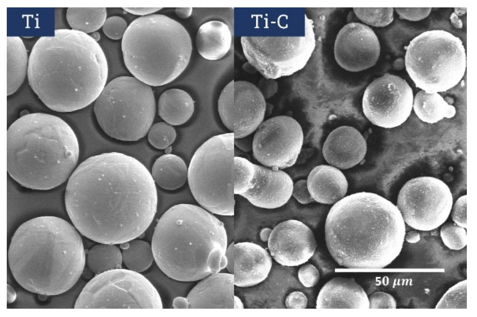
Plasma-atomised spherical commercially pure Titanium (Cp-Ti grade 2, 15-45 µm) was sourced from AP&C, Canada, and carbon black (Mogul®) was sourced from Cabot Corporation, USA. The Cp-Ti/C powder mix, containing 2.7 wt% of carbon, was prepared by mechanical blending using a Turbula T2F from WAB Group, for a minimum of 3 hours. This method produced a homogeneous distribution of Ti particles coated with a thin layer of C nanoparticles, as displayed in Figure 2. The raw powders and powder mixes’ flowability was assessed using a GranuDrum™ from GranuTools, Belgium, at different rotation speeds and with both increasing and decreasing rotation speeds. Furthermore, the absorptivity of different powder layers was determined for both individual powders and powder mixtures using a Lambda 950PE Spectrometer from Perkin Elmer, equipped with an integration sphere.

Laser Powder Bed Fusion Processing

The LPBF procedure was conducted with a TruPrint 1000 machine from Trumpf GmbH, equipped with a 200 W fibre laser (30 µm diameter), operating under an argon atmosphere to limit the oxygen concentration to 100 ppm. Specimens were made on a Ti6Al4V substrate using the laser parameters optimised and detailed in Table 1. The Volumetric Energy Density (VED) is calculated as V E D = P / V h t , with the laser power P in W, the scanning speed V in m m / s , the hatching or distance between two laser paths h in m m , and the layer thickness t in m m . Two different laser parameters were chosen; one with high energy density and the second one with low energy density, respectively referred to TiC-H and TiC-L in the rest of the paper. The scanning technique employed was bi-directional laser scanning with a rotation of 67° between each layer. Tensile samples were fabricated according to ASTM E8M specifications, included in the Supplementary Information (Figure S1 and Table S1). The printing orientation was aligned with the axis of the samples, enabling the production of up to 24 tensile samples at once.

Heat-Treatment

The as-built samples were placed in a quartz tube in an Argon environment and subjected to heat treatment at 880°C for 24 hours in a Nabertherm oven, to control the Ti and TiC microstructures and alleviate thermal stresses caused by the LPBF process.

Microstructural and Mechanical Characterization

The samples were sliced longitudinally and transversely to the building direction, ground with SiC paper, polished with various grades of diamond paste, and finalised with OP-S solution (Struers, Denmark). Microstructural analysis was conducted using a Scanning Electron Microscopy (SEM) with Secondary (SE) and Backscattered Electron (BSE) detectors, as well as Electron Backscatter Diffraction (EBSD) and Energy Dispersive X-Ray Spectroscopy (EDS) detectors from the manufacturers FEI, ZEISS, Oxford Instruments, AMETEK, and Oxford Instruments. The samples porosity was assessed using low-magnification Secondary Electrons micrographs and X-ray Computed Tomography (XCT, Phoenix V|tome|x M from Weigate Technologies). Image analysis was performed with a custom Python script, each time considering at least five different micrographs. The TiC reinforcement content was assessed at different scales, using low-magnification for unmelted TiC particles, and high-magnification for melted TiC (both dendritic and granular). Etching with the OP-S solution revealed the Ti grains clearly, eliminating the need for additional etching solutions. X-Ray Diffraction (XRD) using a PANalytical X’Pert PRO with PIXcel source operated at 45 kV and 40 mA was employed to describe the phase composition.
Tensile properties at room temperature were assessed on heat-treated samples following the ASTM 8M/E8M standard, using a Zwick Series E tensile machine with a 100 kN cell force, and a strain rate of 8.33 10 5   s-1 [33]. The strain rate was assessed through three methods: utilizing a Zwick-provided clip-on extensometer for feedback on the tensile machine, attaching a strain gage to the rear of the sample to measure elastic properties, and employing a GOM Digital Image Correlation System to focus on the front of the sample for the measurement of the fracture strain and strain uniformity. Two unloading cycles were conducted for each tensile test: one at 300 MPa and another at 700 Mpa, to assess the elastic behaviour of the sample and determine the Young’s modulus. The technique involved averaging data from a minimum of four samples. The fracture surfaces were examined using both scanning electron microscopy (SEM) and optical microscopy (OM).

Results and Discussion

As-Built Microstructure

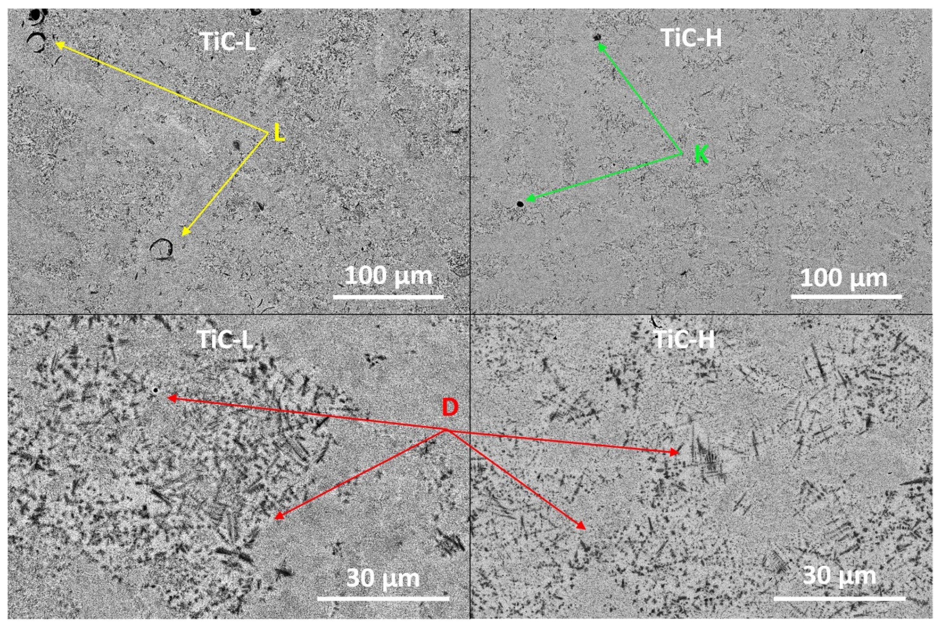
The as-built microstructures of both TiC-H and TiC-L are shown in Figure 3. In both cases, TiC dendrites are visible in black (red D), spread within the Ti matrix. The dendrites size and volume fraction vary over the analysed surface; however, the overall distribution is homogeneous. In addition, dendrites do not show any significant orientation. Both those facts suggest a strong Marangoni convection in the meltpool. The Secondary Dendrite Arm Spacing measured for TiC-L tends to be smaller than that for TiC-H (590±140 nm vs 420±150 nm), which correlates with a lower cooling rate as expected when using a higher laser power during processing. The observed TiC morphology is coherent with the reported work on highly loaded Ti-TiC MMCs [14,23,34] but differs from the whiskers found at lower TiC content [18,19]. In TiC-L, several lack-of-fusion defects appear as circular, as a consequence of non-fully welded particles (yellow L). A few spherical pores are also noticed, probably due to gas entrapment. More rarely, un-melted C agglomerates can be found (Supplementary Material Figure S2), and can be interpreted as due to incomplete dispersion of C during the mixing process. In TiC-H, the majority of porosities are spherical (green K), while C agglomerates have disappeared. These observations would indicate that the energy density was too low with TiC-L parameters.
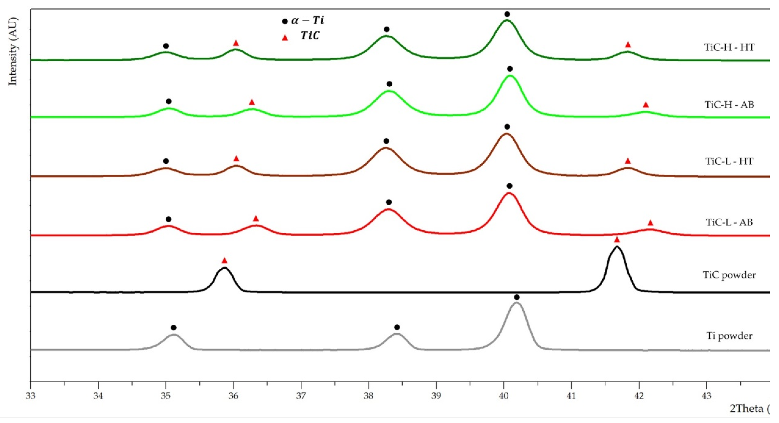
The phase analysis of XRD patterns of as-built MMCs produced with both high and low energy density reveal alike patterns containing αTi and TiC phases (Figure 4 for selected 2-θ angles between 33° and 44°, Supplementary Information Figure S3 for full XRD patterns). The absence of C phases suggests that it fully reacted with Ti to produce TiC. It is challenging to distinguish αTi from the martensitic α’−Ti phase in the produced samples, as both possess similar unit cells, leading to a high peaks overlap. The fast cooling conditions associated to plasma-atomization and LPBF suggest however that martensitic α’−Ti is the most likely phase. These results are in a good agreement with the previously reported phase identifications by Wisocki et al. 2017 and Attar et al. 2017 [35,36]. In Figure 4, the MMCs patterns can be compared with those from Cp-Ti and TiC powders, used as references. The powders stress condition being unknown, a comparative stress assessment will be done in this section. A comparison with the heat treated MMCs, considered as relaxed, will be done in the next section. The MMCs TiC peaks exhibit a clear shift to higher 2-θ angles from the stoichiometric TiC powder to the as-built MMC indicating either a difference in residual stress, a lowered lattice constant, or both. Multiple reports have indeed indicated a correlation between the C/Ti ratio and the TiC lattice constant [31,32,34]. MMC αTi peaks, on the other hand, display a, comparatively low, shift to lower angles form the Ti powder peak positions also indicate the presence of residual stresses in the matrix. The origin of residual stress in MMC produced by LPBF is, typically, due, on the one hand, to difference of coefficient of thermal expansion and, on the other hand, to rapid solidification induced by the LPBF process.

Heat-Treated Microstructure

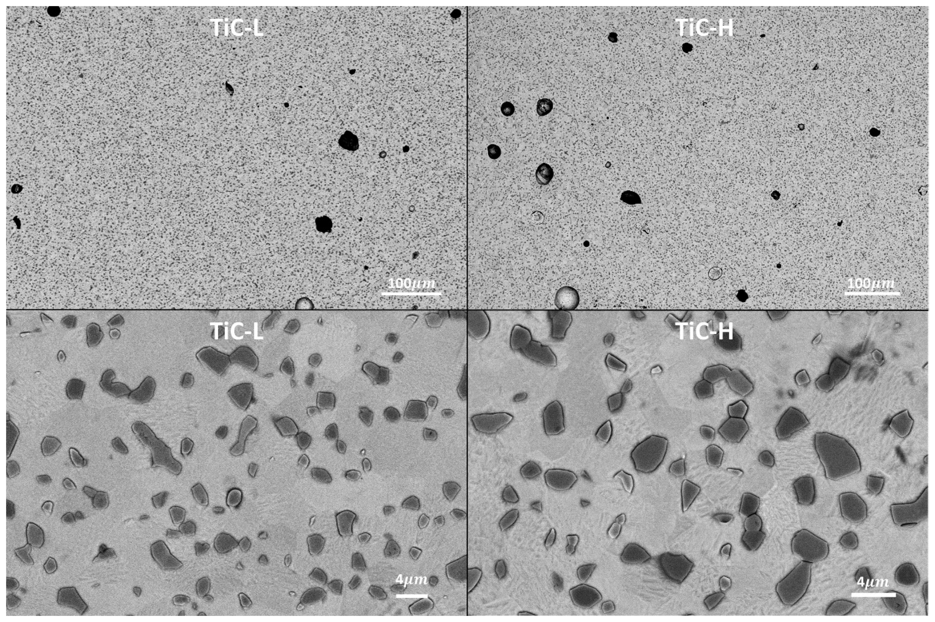
After heat treatment, the TiC dendritic microstructure is fully converted into an equiaxed microstructure for both TiC-H and TiC-L, as displayed in Figure 5. TiC grains appear very homogeneous in terms of spatial distribution and size. Defects sizes and shapes are similar to those discussed in the as-built conditions. The effective reinforcement contents measured by image analysis on low magnification SEM micrographs such as the upper ones in Figure 5 are, respectively, 20.6±3.2 vol% and 19.9±2.2 vol% for TiC-H and TiC-L. Converting in at% by assuming a full carbon reaction and a single lattice constant, the representative TiCx has a C/Ti ratio close to 0.5. The conversion from Ti+C into TiCx would, hence, proceed according to the reaction:
C + 2 T i y i e l d s 2 T i C 0.5
in accordance with the literature expected stable C/Ti ratio of 0.57 [31]. As the Young’s modulus is reported to decrease with the C/Ti ratio (from 450 GPa for TiC, to 350 GPa for TiC0.5 [27]), the stiffness improvement for a given reinforcement content will be reduced [31,32,34]. Using the standard Hashin-Shtrickman bounds, 20 vol% of TiC0.5 leads to a Young’s modulus ranging from 139 to 146 GPa [37]. 20 vol% of TiC would lead to 143–154 GPa, and 12 vol% of TiC, a more realistic estimate considering a complete reaction of the 2.7 wt% C, 131–139 GPa. Comparing this last estimate to the first one (139-146 GPa), it is concluded that, in this case, the stiffness loss induced by a lower C/Ti ratio is more than compensated by the corresponding increase in reinforcement volume fraction. This remark is of qualitative nature only, as the literature data on stiffness variation with the C/Ti ratio is overall lacking, and may vary between authors [27,38].
EBSD maps (available in the Supplementary Material, Figure S3) and high magnification BSE micrographs (Figure 5, bottom) analysis show a mostly α-Ti matrix and the full conversion of dendrites into equiaxed grains after the heat treatment. Statistical analysis of the microstructure shows a Ti grain size of 2.7±1.7 µm and 3.1±2.2 µm for TiC-L and TiC-H, and a TiC grain size of 1.3±0.9 µm and 1.4±0.9 µm. The higher grain sizes in TiC-H would be consistent with higher LPBF process temperatures; however, the magnitude of the changes is not significant considering the standard deviations. Overall, microstructures are quite homogeneous, and the average grain size is small considering the 24-hour heat treatment. In the sole study, to the authors knowledge, on heat-treated in-situ Ti-TiC produced by LPBF by Dadbakhsh et al., Ti grain size (β-Ti width: 83±18 µm) is much higher in as-built condition, and TiC whiskers are about 2.5 times smaller (width: 190±62 µm) [18]. However, during the heat treatment (1 h of ageing at 400 °C or 600 °C), α-Ti grains (width: 39±10 nm) precipitate and refine β-Ti (width: 23±13 µm). The heat treatment did not display a significant effect on the size of TiC whiskers due to its duration and temperature. Contrary to their observations, in this case, TiC grains appear to decorate the Ti grain boundaries which represent a pinning force limiting the extent of grain growth.
The XRD patterns of heat-treated (HT) samples show that the Ti and TiC peaks are moving to lower 2-θ angles compared to the as-built (AB) conditions, which indicates a reduction of tensile residual stresses. The shift of the Ti peaks, which is significantly smaller than the TiC ones, suggests that the matrix has a significantly lower residual stress than the reinforcement in the AB condition. The matrix being able to accommodate the stresses more effectively due to its larger volume is expected. The shift between TiC powder and HT condition suggests a difference in lattice constant, compressive residual stresses in the powder, or both. Considering the full process for TiC, the heat treatment relaxes the strong residual stresses in the TiC phase, which were present after the LPBF process.
Additionally, the C/Ti ratio decreases throughout the whole process. In the case of Ti, we expect no significant lattice changes and observe a reduction in tensile residual stresses throughout the entire process.

Density Characterization

XCT analysis of the samples showed a density >99.8% for both sets of samples, with a homogeneous distribution of defects. The density was computed on the whole sample as well as by excluding the surface regions. There was no significant difference between the two analyses. Representative XCT porosity 3D views of TiC-H and TiC-L tensile bars are available in the Supplementary Information, Figure S5. The resolution of XCT measurements for such Ti-based samples is 20 µm (twice the voxel size) and, hence, cannot resolve small porosities. Consequently, it was complemented by image analysis of SEM micrographs. Densities measured by image analysis were indeed lower, with 99.2±0.4% for TiC-L and 98.9±0.9% for TiC-H. It indicates a prevalence of porosities below 20 µm in both sets of samples. These small porosities could potentially be removed by replacing the heat-treatment process with a Hot Isostatic treatment.
Table 2. XCT density characterization of the whole sample as well as the hatching region (surface zones removed). The XCT resolution is 20µm. Density measurements by image analysis of SEM micrographs in the hatching region.
XCT measurement Image analysis
Sample Sample density [%] Hatching density [%] Hatching density [%]
TiC-L 99.8 99.8 99.2
TiC-H 99.9 99.9 98.9

Mechanical Properties in Heat Treated Conditions

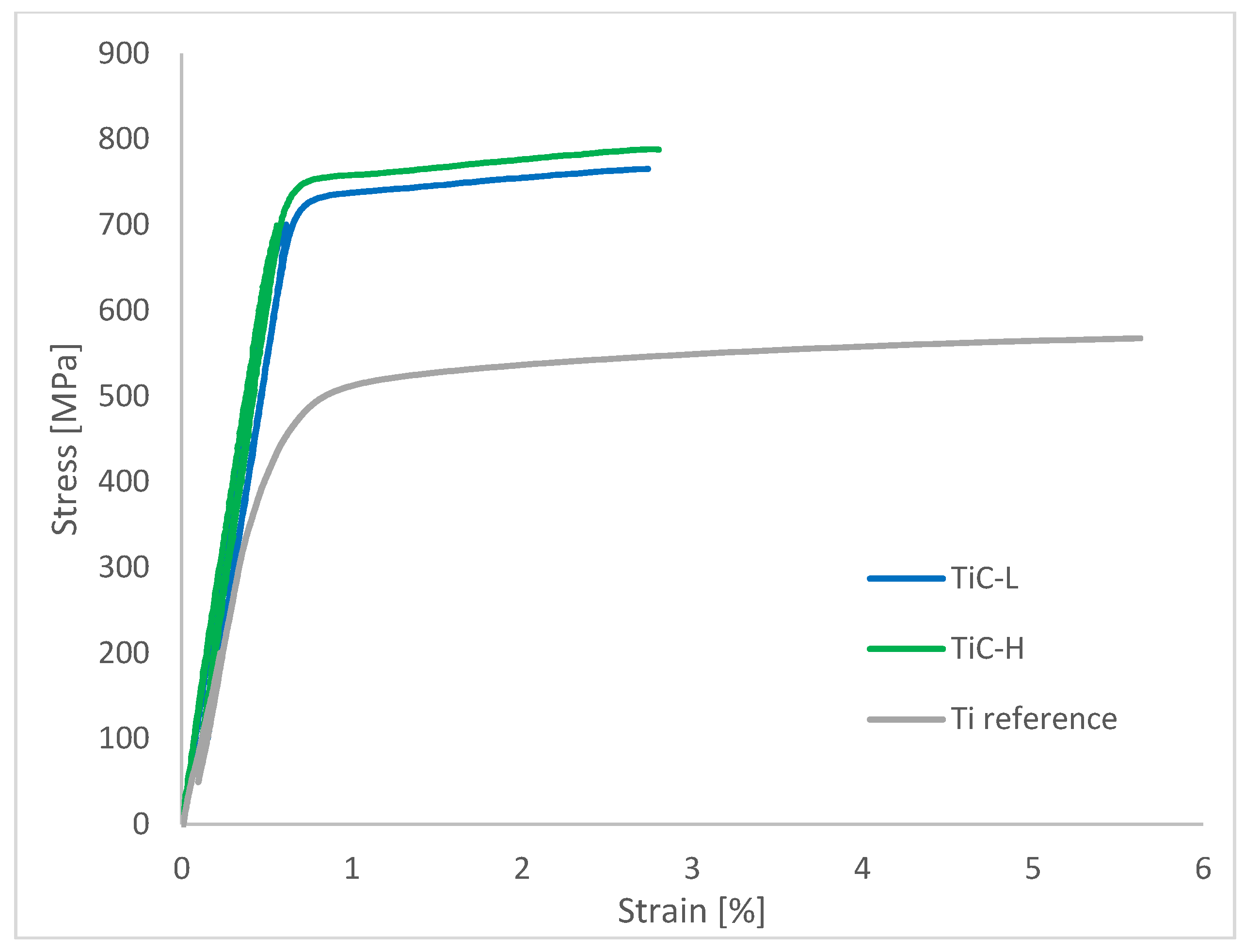
Typical stress-strain curves of both samples sets are compared to the Ti reference in Figure 6, and quantified mechanical properties are provided in Table 3. Both TiC-L and TiC-H showed significantly improved Young’s moduli (22% and 27% increase, respectively), yield strengths, and ultimate tensile strengths. The difference in reinforcement volume fraction measured by image analysis between TiC-L and TiC-H being below one percent, it cannot account for more than a 1% increase in Young’s modulus, according to Hashin-Shtrickman bounds. The origin of the remaining 4% increase can be suggested by considering the two sets of calculated Hashin-Shtrickman bounds, for 20 vol% of TiC0.5, and 20 vol% of TiC. The TiC-L measured Young’s modulus falls in the middle of the 20 vol% TiC0.5 bounds, and close to the lower bound of 20 vol% TiC. On the other hand, the TiC-H Young’s modulus is in the middle of the 20 vol% TiC bounds, and clearly over the upper bound of 20 vol% TiC0.5. For MMCs with particles reinforcement, one would expect a mechanical behaviour close to that of the Hashin-Shtrickman lower bound, i.e., the microstructure can reasonably be approximated by a homogeneous distribution of a spherical stiffer phase within a more compliant matrix. The powder mix being the same for the two sets of samples, one could propose that the difference in LPBF energy density led to a C/Ti ratio difference which induced the 4% difference in Young’s modulus. This could be explained by the presence of unreacted C in the TiC-L samples (below the XRD detection threshold), by a significant loss of Ti due to spattering and/or evaporation, or by a change in reaction between Ti and C leading to a new C/Ti ratio distribution.
Young’s moduli measured at 300 MPa and 700 MPa (i.e., just before the yield point) were not significantly different, which suggests that the reinforcement did not sustain damage during elastic deformation. Loss of reinforcement might occur when the reinforcement phase fails prematurely due to pre-existing flaws or when the interface between the matrix and reinforcement is weak.
Similarly to the Young’s modulus increase, the strengthening was more pronounced on TiC-H: the yield strength and ultimate tensile strength increased by 44% and 34%, instead of 41% and 30% for TiC-L. The work hardening rate was constant for both sets, suggesting similar deformation mechanisms. The fracture strain is 2.8% for TiC-H samples, with offers the possibility of industrial applications. It is noted that TiC-H have both an increased strength and an increased ductility compared to TiC-L. We conclude that the high energy process parameters produce a more performant MMC despite the increased porosity. This may be the consequence of eliminating the very detrimental lack of fusion defects. On the other hand, the standard deviation of mechanical properties is lower for the TiC-L samples, i.e., the properties are more reproducible, potentially due to the absence of stochastic keyholes.
To the authors knowledge, the above mechanical properties can only be compared with those reported by Dadbakhsh et al., who produced βTi-6 vol% TiC from a mixture of Ti and Mo2C [18,19]. The matrix observed is mainly βTi in as-built condition thanks to the presence of Mo but converts to αTi during ageing at 600°C. They mainly characterised the MMCs in compression, but also performed tensile tests in one of their studies. They achieved a Young’s modulus of 126 GPa before heat treatment, a result in line with this study considering the difference in reinforcement content. However, the stiffness reinforcement was completely lost after the heat treatment (i.e., Young’s modulus measured after heat treatment is comparable to the one of pure Titanium). They also measured UTS of up to 1261 MPa in tension (after heat treatment), and stresses up to 1642 MPa in compression (in as-built condition). The fracture strain achieved after heat treatment was very similar to the one reported here, but it is likely to decrease significantly with increased TiC content. We conclude that the results presented in this study represent the highest, thermally stable, stiffness increase obtained through LPBF of a Ti-based MMC.
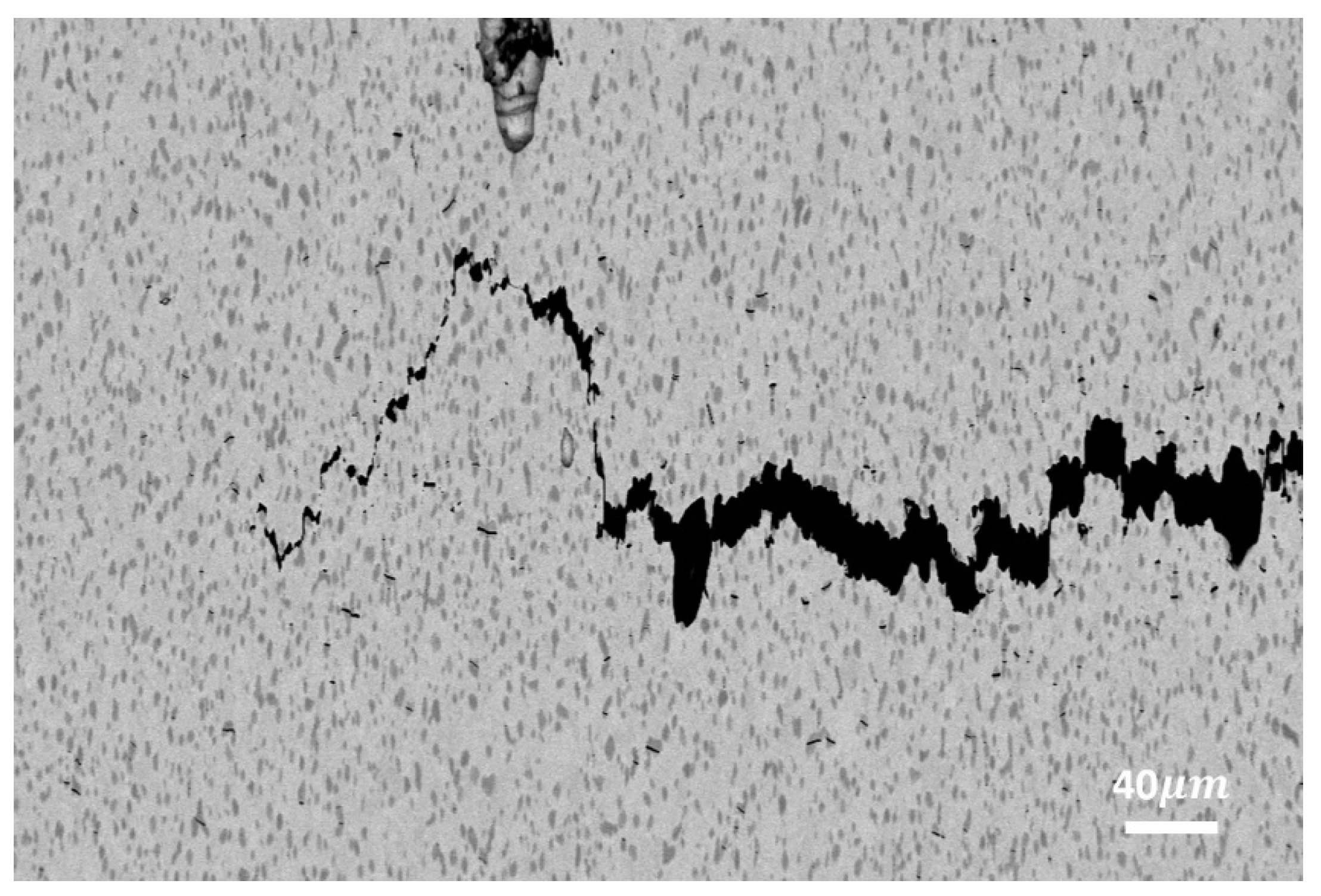
The study of the fracture surface as well as cross-sections of sub-surface cracks can give insight into the deformation and fracture behaviour occurring in the MMC. In both TiC-L and TiC-H, the fracture surface shows ductile dimples in the matrix, while TiC particles are not clearly visible. Sub-fracture surface cross-sections are more helpful to assess the fracture behaviour, as illustrated in Figure 7, showing a crack parallel to the fracture surface, at an approximate distance of 1mm. It shows that the crack propagates in the Ti matrix and is deflected by TiC particles, leading to a strongly oscillating crack path, associated with particle cracking, matrix voiding, and interface failure. High plastic deformation along the main crack suggests a high energy dissipation during crack propagation, and, therefore, a significant fracture toughness.

Conclusions

Titanium-Titanium Carbide Metal Matrix Composites (MMC) were fabricated via Laser Powder Bed Fusion (LPBF) taking advantage of the in-situ reaction between Titanium and Carbon to form Titanium Carbide. Two sets of MMCs were manufactured, with low (TiC-L) and high (TiC-H) laser energy density, respectively. The microstructure and mechanical properties of the heat-treated MMCs were extensively analysed.
  • A density >99% and >98% was achieved in TiC-L and TiC-H, respectively. Porosities with a size above 20 µm accounted for <0.2% of the volume in both cases.
  • A uniform TiC dendritic structure before heat treatment was transformed into equiaxed grains following the heat treatment. The average Ti and TiC grain sizes remained below 1.4 µm and 3.1 µm, for the two levels of energy density.
  • Both TiC-H and TiC-L exhibited significantly improved mechanical properties. Compared to the Ti reference, the Young’s moduli increased by 27% and 22%, the yield strength by 44% and 41%, and the ultimate tensile strength by 34% and 30%. The fracture strain, 2.8% for TiC-H and 2.3% for TiC-L, was remarkably high considering 20 vol% reinforcement content. The superior mechanical properties of TiC-H are attributed to the absence of lack of fusion defects, resulting in the highest Young’s modulus, yield strength, ultimate tensile strength, and fracture strain.

Supplementary Materials

The following supporting information can be downloaded at the website of this paper posted on Preprints.org.

Author Contributions

Conceptualization, Gaëtan Bernard and Vaclav Pejchal; methodology, Gaëtan Bernard; validation, Gaëtan Bernard, Vaclav Pejchal and Olha Sereda; formal analysis, Gaëtan Bernard; investigation, Gaëtan Bernard; data curation, Gaëtan Bernard; writing—original draft preparation, Gaëtan Bernard.; writing—review and editing, all authors; visualization, Gaëtan Bernard; supervision, Olha Sereda and Roland Logé; project administration, Olha Sereda; funding acquisition, Olha Sereda and Vaclav Pejchal. All authors have read and agreed to the published version of the manuscript.

Funding

This research was partially funded by European Space Agency, grant number 4000132091/20/NL/MH/ac.

Data Availability Statement

Data will be made available on request.

Acknowledgments

The authors would like to thank Professor Andreas Mortensen for his suggestion of C precursors for in-situ Ti-TiC MMC production. The authors are grateful to Laura Gyger for her help with artwork and graphical abstract formatting. The authors would like to extend their gratitude to the Additive Manufacturing and Component Reliability Group of CSEM, the Laboratory of Thermomechanical Metallurgy from EPFL, as well as Materials and Processes Section from ESA for their technical support and recommendations.

Conflicts of Interest

The authors declare no conflict of interest.

Declaration of Generative AI and AI-Assisted Technologies in the Writing Process

During the preparation of this work the authors used QuillBot in order to improve fluency. After using this tool, the authors reviewed and edited the content as needed and take full responsibility for the content of the published article.

References

  1. T. Saito, ‘A cost-effective P/M titanium matrix composite for automobile use’, Adv Perform Mater, vol. 2, no. 2, pp. 121–144, Jun. 1995. [CrossRef]
  2. K. Soorya Prakash, P. M. Gopal, D. Anburose, and V. Kavimani, ‘Mechanical, corrosion and wear characteristics of powder metallurgy processed Ti-6Al-4V/B4C metal matrix composites’, Ain Shams Engineering Journal, vol. 9, no. 4, pp. 1489–1496, Dec. 2018. [CrossRef]
  3. C. Mohanraj, K. M. N. Kumar, K. PraveenKumar, and S. Mukesh, ‘Development of AA6082 based metal matrix composite using Sic,Ti,Ni,Cr by conventional casting technique’, Materials Today: Proceedings, p. S2214785320333022, May 2020. [CrossRef]
  4. M. Kouzeli and D. C. Dunand, ‘Effect of temperature and strain rate on the compressive flow of aluminum composites containing submicron alumina particles’, Metall Mater Trans A, vol. 35, no. 1, pp. 287–292, Jan. 2004. [CrossRef]
  5. T. M. T. Gofrey, P. S. Goodwin, and C. M. Ward-Close, ‘Titanium Particulate Metal Matrix Composites—Reinforcement, Production Methods, and Mechanical Properties’, Adv. Eng. Mater., vol. 2, no. 3, pp. 85–91, Mar. 2000. [CrossRef]
  6. C. Cai et al., ‘In-situ TiB/Ti-6Al-4V composites with a tailored architecture produced by hot isostatic pressing: Microstructure evolution, enhanced tensile properties and strengthening mechanisms’, Composites Part B: Engineering, vol. 164, pp. 546–558, May 2019. [CrossRef]
  7. M. A. Lagos, I. Agote, G. Atxaga, O. Adarraga, and L. Pambaguian, ‘Fabrication and characterisation of Titanium Matrix Composites obtained using a combination of Self propagating High temperature Synthesis and Spark Plasma Sintering’, Materials Science and Engineering: A, vol. 655, pp. 44–49, Feb. 2016. [CrossRef]
  8. J. Shi and Y. Wang, ‘Development of metal matrix composites by laser-assisted additive manufacturing technologies: a review’, J Mater Sci, vol. 55, no. 23, pp. 9883–9917, Aug. 2020. [CrossRef]
  9. Y. Hu and W. Cong, ‘A review on laser deposition-additive manufacturing of ceramics and ceramic reinforced metal matrix composites’, Ceramics International, vol. 44, no. 17, pp. 20599–20612, Dec. 2018. [CrossRef]
  10. M. A. Mahmood, A. C. Popescu, and I. N. Mihailescu, ‘Metal Matrix Composites Synthesized by Laser-Melting Deposition: A Review’, Materials, vol. 13, no. 11, p. 2593, Jun. 2020. [CrossRef]
  11. W. H. Yu, S. L. Sing, C. K. Chua, C. N. Kuo, and X. L. Tian, ‘Particle-reinforced metal matrix nanocomposites fabricated by selective laser melting: A state of the art review’, Progress in Materials Science, vol. 104, pp. 330–379, Jul. 2019. [CrossRef]
  12. H. Attar, S. Ehtemam-Haghighi, D. Kent, and M. S. Dargusch, ‘Recent developments and opportunities in additive manufacturing of titanium-based matrix composites: A review’, International Journal of Machine Tools and Manufacture, vol. 133, pp. 85–102, Oct. 2018. [CrossRef]
  13. S. Dadbakhsh, R. Mertens, L. Hao, J. Van Humbeeck, and J. Kruth, ‘Selective Laser Melting to Manufacture “In Situ” Metal Matrix Composites: A Review’, Adv. Eng. Mater., vol. 21, no. 3, p. 1801244, Mar. 2019. [CrossRef]
  14. D. Gu, Y.-C. Hagedorn, W. Meiners, K. Wissenbach, and R. Poprawe, ‘Selective Laser Melting of in-situ TiC/Ti5Si3 composites with novel reinforcement architecture and elevated performance’, Surface and Coatings Technology, vol. 205, no. 10, pp. 3285–3292, Feb. 2011. [CrossRef]
  15. Y. Pan et al., ‘Microstructure and tribological properties of titanium matrix composites reinforced with in situ synthesized TiC particles’, Materials Characterization, vol. 170, p. 110633, Dec. 2020. [CrossRef]
  16. L. Xi et al., ‘Interfacial structure and wear properties of selective laser melted Ti/(TiC+TiN) composites with high content of reinforcements’, Journal of Alloys and Compounds, vol. 870, p. 159436, Jul. 2021. [CrossRef]
  17. P. Bai, P. Huo, Z. Zhao, W. Du, Z. Zhang, and L. Wang, ‘Microstructure evolution and corrosion mechanism of in situ synthesized TiC/TC4 alloy nanocomposites fabricated by laser powder bed fusion’, Ceramics International, vol. 49, no. 2, pp. 2752–2764, Jan. 2023. [CrossRef]
  18. S. Dadbakhsh, ‘Heat treatment possibilities for an in situ βTi-TiC composite made by laser powder bed fusion’, Additive Manufacturing, vol. 36, p. 101577, Dec. 2020. [CrossRef]
  19. S. Dadbakhsh, R. Mertens, K. Vanmeensel, G. Ji, and J.-P. Kruth, ‘In situ transformations during SLM of an ultra-strong TiC reinforced Ti composite’, Scientific Reports, vol. 10, no. 1, Art. no. 1, Jun. 2020. [CrossRef]
  20. C. Zhang, Z. Guo, F. Yang, H. Wang, Y. Shao, and B. Lu, ‘In situ formation of low interstitials Ti-TiC composites by gas-solid reaction’, Journal of Alloys and Compounds, vol. 769, pp. 37–44, Nov. 2018. [CrossRef]
  21. E. Fereiduni, A. Ghasemi, and M. Elbestawi, ‘Unique opportunities for microstructure engineering via trace B4C addition to Ti-6Al-4V through laser powder bed fusion process: As-built and heat-treated scenarios’, Additive Manufacturing, vol. 50, p. 102557, Feb. 2022. [CrossRef]
  22. C. Han et al., ‘Microstructure and mechanical properties of (TiB+TiC)/Ti composites fabricated in situ via selective laser melting of Ti and B4C powders’, Additive Manufacturing, vol. 36, p. 101466, Dec. 2020. [CrossRef]
  23. D. Gu, Y.-C. Hagedorn, W. Meiners, K. Wissenbach, and R. Poprawe, ‘Nanocrystalline TiC reinforced Ti matrix bulk-form nanocomposites by Selective Laser Melting (SLM): Densification, growth mechanism and wear behavior’, Composites Science and Technology, vol. 71, no. 13, pp. 1612–1620, Sep. 2011. [CrossRef]
  24. D. Gu, G. Meng, C. Li, W. Meiners, and R. Poprawe, ‘Selective laser melting of TiC/Ti bulk nanocomposites: Influence of nanoscale reinforcement’, Scripta Materialia, vol. 67, no. 2, pp. 185–188, Jul. 2012. [CrossRef]
  25. Q. Yan, B. Chen, and J. S. Li, ‘Super-high-strength graphene/titanium composites fabricated by selective laser melting’, Carbon, vol. 174, pp. 451–462, Apr. 2021. [CrossRef]
  26. D. K. Das and M. M. Ghosh, ‘On Mechanical Properties of Graphene Sheet Estimated Using Molecular Dynamics Simulations’, Journal of Materials Engineering and Performance, vol. 26, no. 9, pp. 4522–4532, Sep. 2017. [CrossRef]
  27. M. Guemmaz, A. Mosser, R. Ahujab, and B. Johansson, ‘Elastic properties of sub-stoichiometric titanium carbides Comparison of FP-LMTO calculations and experimental results’, Solid State Communications, vol. 110, no. 6, p. 5, Apr. 1999. [CrossRef]
  28. M. Kouzeli, L. Weber, C. S. Marchi, and A. Mortensen, ‘Influence of Damage on the Tensile Behaviour of Pure Aluminium Reinforced with 40 vol. pct Alumina Particles’, Acta Materialia, vol. 49, no. 18, pp. 3699–3709, Oct. 2001. [CrossRef]
  29. T.-C. Lin et al., ‘Aluminum with dispersed nanoparticles by laser additive manufacturing’, Nat Commun, vol. 10, no. 1, p. 4124, Sep. 2019. [CrossRef]
  30. J. H. Abboud and D. R. F. West, ‘In situ production of Ti-TiC composites by laser melting’, J Mater Sci Lett, vol. 11, no. 24, pp. 1675–1677, 1992. [CrossRef]
  31. J. Andrieux, B. Gardiola, and O. Dezellus, ‘Synthesis of Ti matrix composites reinforced with TiC particles: in situ synchrotron X-ray diffraction and modeling’, J Mater Sci, vol. 53, no. 13, pp. 9533–9544, Jul. 2018. [CrossRef]
  32. J. Roger, ‘Synthesis of Ti matrix composites reinforced with TiC particles: thermodynamic equilibrium and change in microstructure’, J Mater Sci, vol. 52, pp. 4129–4141, Dec. 2016. [CrossRef]
  33. E28 Committee, ‘Test Methods for Tension Testing of Metallic Materials’. ASTM International. [CrossRef]
  34. Y. Lin, R. H. Zee, and B. A. Chin, ‘In situ formation of three-dimensional TiC reinforcements in Ti-TiC composites’, MTA, vol. 22, no. 4, pp. 859–865, Apr. 1991. [CrossRef]
  35. B. Wysocki et al., ‘Microstructure and mechanical properties investigation of CP titanium processed by selective laser melting (SLM)’, Journal of Materials Processing Technology, vol. 241, pp. 13–23, Mar. 2017. [CrossRef]
  36. H. Attar, S. Ehtemam-Haghighi, D. Kent, X. Wu, and M. S. Dargusch, ‘Comparative study of commercially pure titanium produced by laser engineered net shaping, selective laser melting and casting processes’, Materials Science and Engineering: A, vol. 705, pp. 385–393, Sep. 2017. [CrossRef]
  37. Z. Hashin and S. Shtrikman, ‘A variational approach to the theory of the elastic behaviour of multiphase materials’, Journal of the Mechanics and Physics of Solids, vol. 11, no. 2, pp. 127–140, Mar. 1963. [CrossRef]
  38. K. Vasanthakumar and S. R. Bakshi, “Effect of C/Ti ratio on densification, microstructure and mechanical properties of TiCx prepared by reactive spark plasma sintering,” Ceramics International, vol. 44, no. 1, pp. 484–494, Jan. 2018. [CrossRef]
Figure 1. MMC In-situ manufacturing process.
Preprints 114459 g001
Figure 2. SEM micrograph of Ti particles: (left) raw and (right) Ti coated with a C layer.
Preprints 114459 g002
Figure 3. SEM BSE micrographs showing representative as-bult microstructure for TiC-L (left) and TiC-H (right). Examples of TiC dendrites are indicated by the red arrows (D), lack-of-fusion defects by the yellow arrows (L) and spherical pores by the green arrows (K).
Preprints 114459 g003
Figure 4. XRD patterns of TiC-L and TiC-H before and after heat treatment as well as reference Ti and TiC powders with 2-θ angles between 33° and 44°. HT refers to heat-treated samples and AB to as-built ones.
Preprints 114459 g004
Figure 5. SEM micrographs of heat-treated TiC-L (left) and TiC-H (right). Top micrographs are typically used to compute porosity and lower ones are typically used to compute reinforcement content.
Preprints 114459 g005
Figure 6. Typical stress-strain curves of TiC-L and TiC-H MMCs as well as Ti reference.
Preprints 114459 g006
Figure 7. Sub-fracture surface cross-section in TiC-L sample after tensile failure. The cross-section was extracted close to the edge of the fracture surface.
Preprints 114459 g007
Table 1. Laser parameters used in LPBF processing. The energy density is calculated as VED = P/Vht, with the laser power P in W, the scanning speed V in mm/s, the hatching h in mm, and the layer thickness t in mm.
Set Laser processing parameters
VED [J/mm3] h [µm] t [µm]
TiC-H 146 40 30
TiC-L 125 40 30
Table 3. Mechanical tensile properties of TiC-L and TiC-H MMCs compared to the Ti reference. E300 and E700 refer to Young’s moduli measurements by unloading at 300 MPa and 700 MPa, respectively.
TiC-L TiC-H Ti
E300 [GPa] 143±1 149±6 117±7
E700 [GPa] 141±1 149±7 -
YS [MPa] 720±2 737±13 512±6
UTS [MPa] 750±13 770±17 576±4
e [%] 2.3±0.4 2.8±0.6 29.3±3.1
Disclaimer/Publisher’s Note: The statements, opinions and data contained in all publications are solely those of the individual author(s) and contributor(s) and not of MDPI and/or the editor(s). MDPI and/or the editor(s) disclaim responsibility for any injury to people or property resulting from any ideas, methods, instructions or products referred to in the content.
Copyright: This open access article is published under a Creative Commons CC BY 4.0 license, which permit the free download, distribution, and reuse, provided that the author and preprint are cited in any reuse.
Prerpints.org logo

Preprints.org is a free preprint server supported by MDPI in Basel, Switzerland.

Subscribe

© 2024 MDPI (Basel, Switzerland) unless otherwise stated