1. Introduction
This research aims to complement a paper presented at the REHABEND 2022 Congress [
1], which analysed the use of drones for the inspection of architectural heritage elements, unique constructions and ancient or fragile structures, including two Roman bridges. For that paper, the researchers carried out an experimental inspection of several ancient structures in accordance with the regulations of the time. In other words, the inspection was purely visual, analysing only the visible elements. Some of the structures included in the study were ancient masonry bridges. In these cases, part of the inspection could not be carried out due to the presence of river currents that made it impossible to see and access certain elements. However, the analysis of such elements can be essential to obtain a complete assessment, given the number of damages originating from the foundation that occur in this type of structure [
2,
3].
In addition to the experience described above [
1], there have been many attempts to use drones to inspect heritage elements [
4,
5,
6]. These have shown excellent results, all of which demonstrate the importance of using drones for this purpose: drones make it possible to get close to heritage structures in order to analyse them, reducing the risks for the inspectors and for the structures themselves, and allowing a complete visual inspection to be carried out with optimal levels of quality and precision.
Every inspection begins with an analysis of the foundation and the start of construction [
4]. If these elements are visible, a visual inspection may be a perfectly acceptable way of analysing them. In most cases, however, these elements are neither visible nor accessible. This means that possible defects in the foundation can only be detected indirectly through external signs visible in other elements of the bridge, e.g., excessive movements, deformations or cracks [
7,
8]. Therefore, the geometric and pathological characteristics of the substructure and superstructure must be carefully monitored. In practice, the first procedure that can (and should) be used to correctly identify problems related to a foundation’s deficient structural response is the observation and subsequent analysis of symptoms that may occur in the superstructure as a result of twisting, absolute settlement or differential settlement in the foundation. The drone has proven to be a key and very useful tool in this task.
However, in many cases where foundation elements are in a poor state of stability and present a reduced level of safety, these deficiencies do not manifest themselves in obvious external symptoms at the time of inspection. This is all the more serious if one considers the risk of reaching extreme situations or unexpected instability, as well as large movements or even partial or total collapse. It is therefore not possible to carry out a complete inspection that provides total certainty as to the real state and stability of an ancient structure when part of the monument is underwater.
The main drawback of localised damage to the foundation of structures (not only bridges) is the difficulty of visual inspection. If the inspection is carried out during the summer, it may be somewhat easier to detect possible deterioration problems in the structural element in question, but this is not always possible. This detection can even be extended to problems caused by the deterioration of the entire soil-foundation complex. In the particular case of bridges, the foundation usually starts at a certain depth and is typically either underwater or invisible to inspection because it is covered by sediment. In such circumstances, inspection is understandably an arduous (if not unmanageable) task if it is to be done visually.
Damage directly to the foundation is caused by two main factors: the deterioration of the materials making up the substructure and the poor performance of the soil-foundation complex in response to the various actions to which the complex is exposed [
2,
3,
7,
8]. Factors such as the action of water currents on submerged elements or the increase in hydraulic velocity of the current due to a reduction in the cross-section of the channel or a change in the longitudinal profile can also cause such deficiencies.
Therefore, in addition to a detailed visual inspection of the foundation, it is important to estimate, as far as possible, the type and dimensions of the foundation element, the type of terrain, the longitudinal profile of the riverbed, the cross-section upstream and downstream of the structure, the degree of cleaning of the channel and the layout of the drag elements in it. These are all areas where a drone can reveal certain deficiencies and limitations.
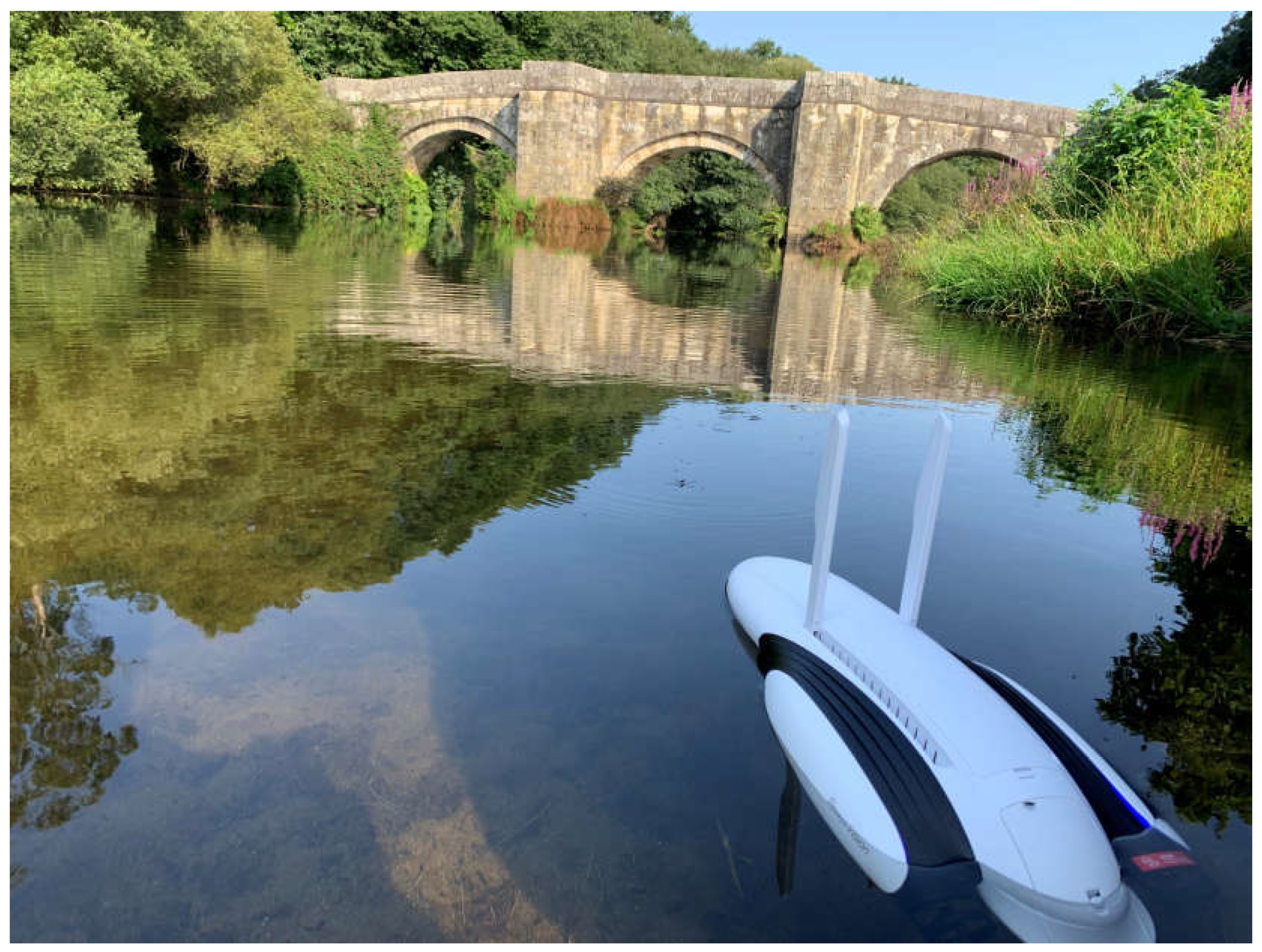
Special inspection techniques are often required to provide enough information to ensure a complete understanding of the actual condition of the structure and the detailed bathymetry of the channel beneath it and in its immediate vicinity, both upstream and downstream. In line with the above, just as the use of a drone has been proposed for visual inspection, an equivalent tool has been sought to inspect the submerged part of structures. This has led to the underwater drone (
Figure 1). At the time of writing, no known drone model has been used for this purpose.
2. Objectives
Once again, our research is based on the idea that structures need to be inspected in order to obtain the necessary data to determine their functional, structural and aesthetic condition over time. Therefore, the main objective of this paper is to verify the applicability of underwater drones for inspecting the submerged part of the substructure of an old masonry bridge, in view of the large number of bridge disasters and collapses linked to failures in their foundations, and as a complement to the visual inspections for which the common drone has proven effective.
The author’s experience and analysis of three underwater inspections carried out by him on three large ancient river bridges (the Roman Segura Bridge, the San Lorenzo Bridge and the Brandomil Bridge) will serve as a basis for verifying the achievement of the research objective.
A PowerVision PowerDolphin PDW10 (4K) underwater drone was used to carry out these inspections (
Figure 1). It weighs 2,268 g and is used in conjunction with a remote control linked to an iPad (iOS system) for better viewing. This underwater drone has a 4K HD camera with multiple resolution settings and the ability to rotate up to 220° on its own axis, allowing it to see above and below the water’s surface. It also has a built-in GPS with bathymetric detection and “return home” functions. It has a two-hour battery life and can reach a maximum speed of 4.50 m/sec (16.20 km/h).
3. Examples of Experimental Underwater Inspections
Several studies have discussed the deliberate intention of ancient engineers, especially Roman engineers, to locate buildings, especially bridges, in places with good foundation conditions [
9]. Eugène Viol-let-le-Duc suggested that after the fall of the Roman Empire, technical innovation was practically non-existent until the Carolingian period [
10]. At the end of the Middle Ages, the Renaissance revived the Greco-Latin tradition in architecture and construction. The Renaissance thus imitated this tradition to an unprecedented degree. In the centuries that followed, this imitation continued with less intensity, but always on the premise of applying what had proven effective. The foundation of masonry structures is one of the clearest examples of this.
With the above premise in mind, a sample of three granite rock bridges from different periods and geographical locations on the Iberian Peninsula was selected to test the suitability of using an underwater drone to inspect their submerged elements:
The Segura Bridge, a thousand-year-old Roman bridge in Extremadura, on the border between Spain and Portugal;
The Brandomil Bridge, a medieval bridge in Galicia; and
The San Lorenzo Bridge, a nineteenth-century Roman-inspired bridge in the northwest of the peninsula, on the border between Spain and Portugal.
In all three cases, the presence of a river of a certain size under the bridge, the geometric dimensions of the structures to be analysed and the inaccessibility of certain areas (in all three cases, several of the central piers are submerged in river water) make the selected bridges ideal for verifying the validity of the use of the underwater drone. In addition, the beauty, significance and historical and heritage value of each of the selected bridges undoubtedly adds value to their inspection. The fact that they are of great historical, archaeological, engineering and pathological interest reinforces this idea.
The three inspections were carried out during the summer, when the flow of the rivers is lower. At this time of year it is much easier to navigate the device and detect any deterioration problems in the foundation elements or deficiencies caused by the poor behaviour of the soil-foundation complex.
3.1. The Roman Segura Bridge
Located on the border between Spain and Portugal, in the province of Cáceres, the Segura Bridge spans the Erjas River, a tributary of the Tagus. It still carries road traffic today, linking the Extremaduran town of Piedras Albas with the Portuguese town of Segura. It is estimated to have been built around the same time as the nearby Alcántara Bridge, in the 2nd century AD [
11,
12].
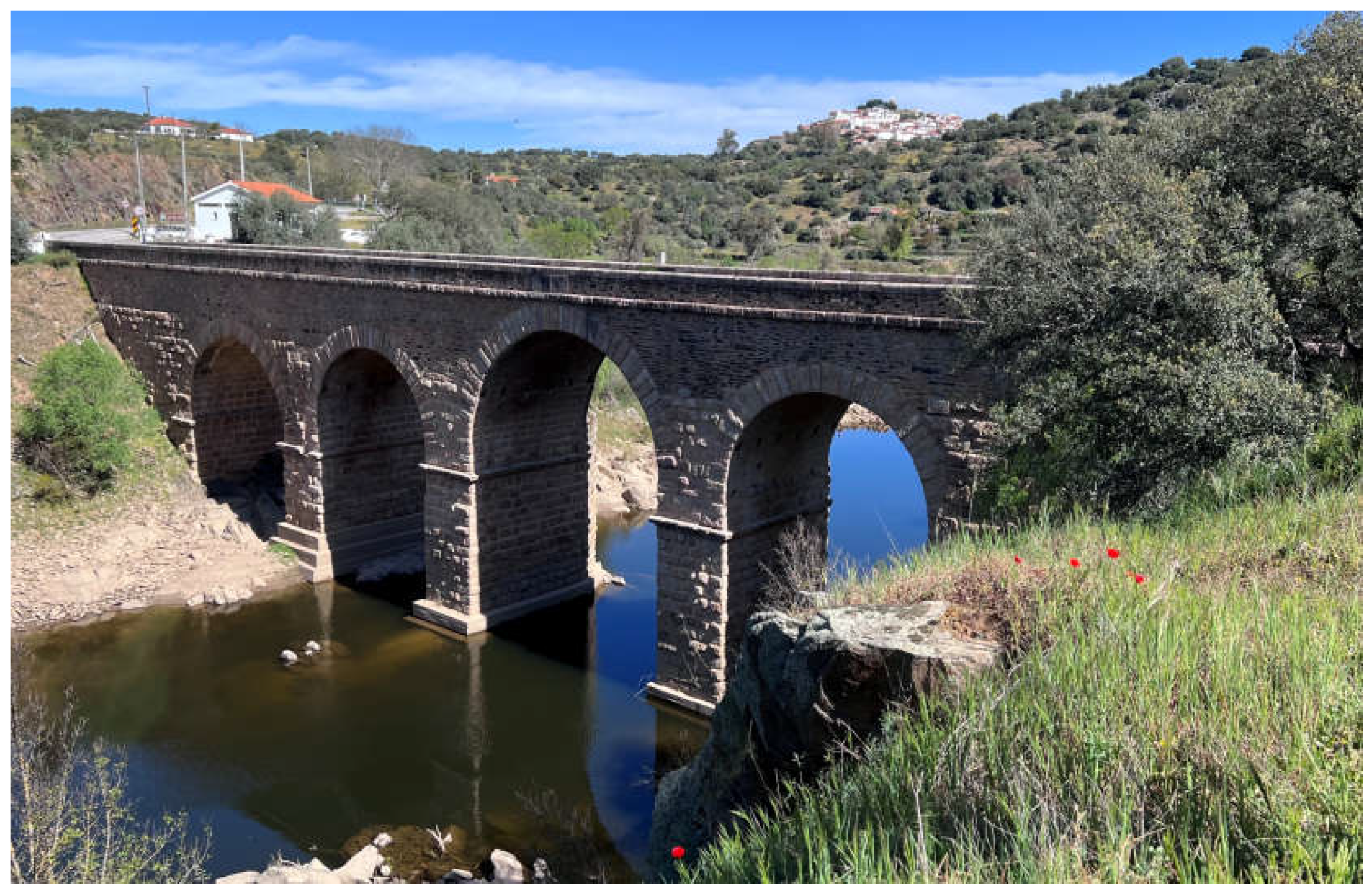
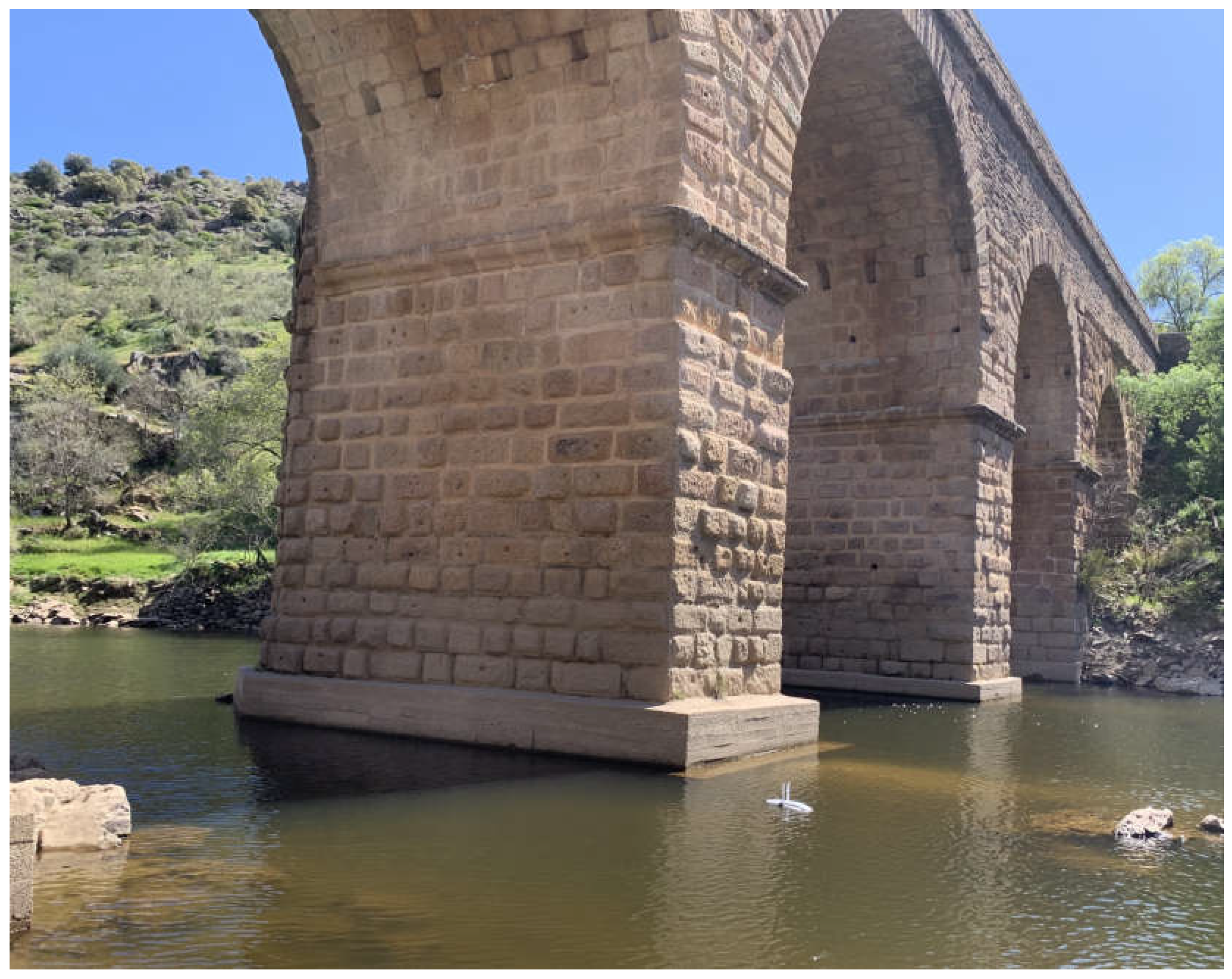
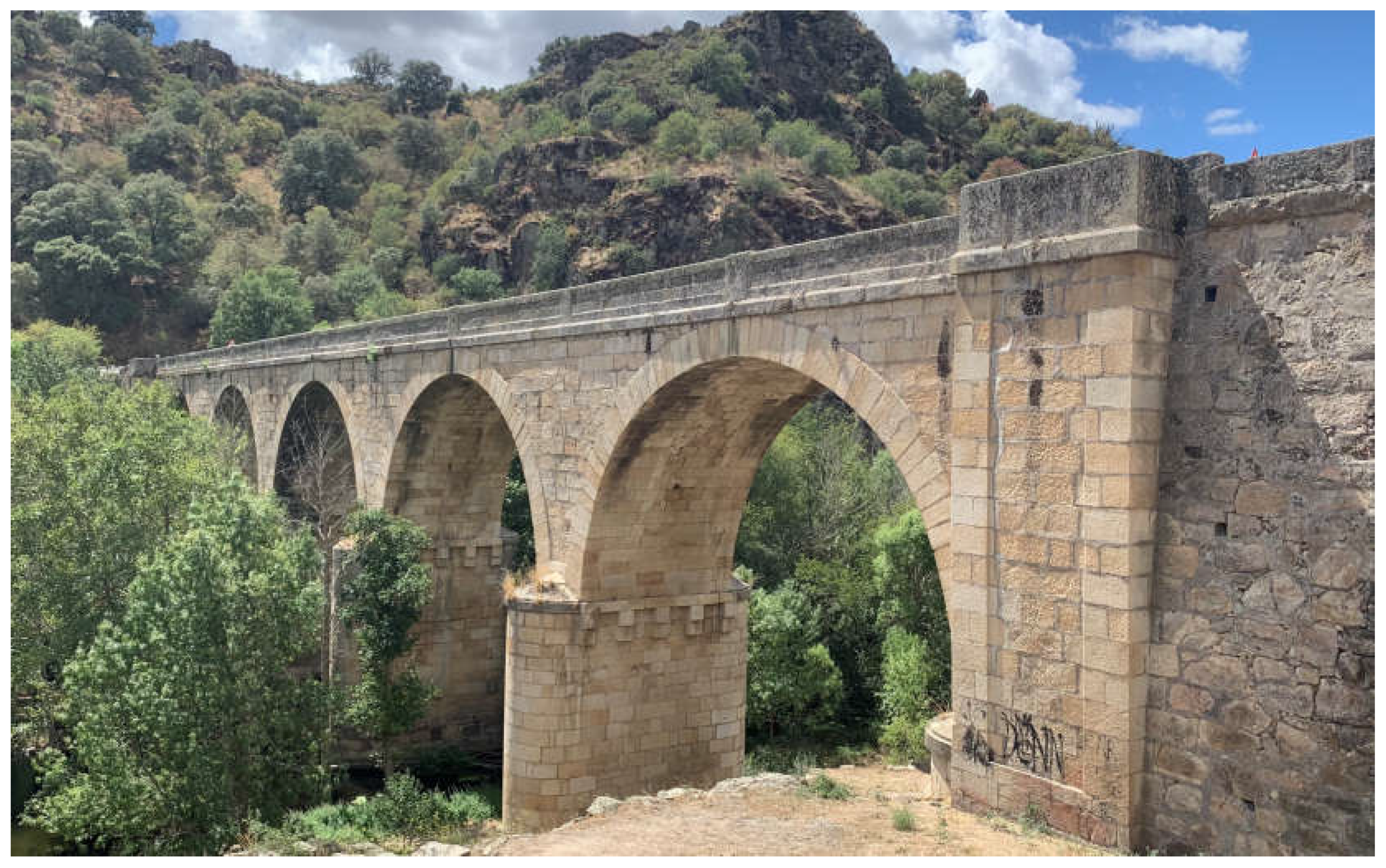
The bridge has five spans with arches of unequal span (
¡Error! No se encuentra el origen de la referencia.). The largest is in the middle, with a span of 10.50 m [
9]. The thickness of the bridge varies slightly between 2.85 m and 3.00 m.
Figure 2.
General view of the southern (downstream) side of the Segura Bridge (photo by the author).
Figure 2.
General view of the southern (downstream) side of the Segura Bridge (photo by the author).
The entire bridge as it is currently preserved is not the original Roman one. There is evidence of a reconstruction in the 16th century and another in the 19th century [
13], the latter involving masonry that contrasted with the Roman ashlar and allowed the bridge platform to be adapted to the traffic of the time, as well as facilitating the drainage and evacuation of water [
12,
13,
14].
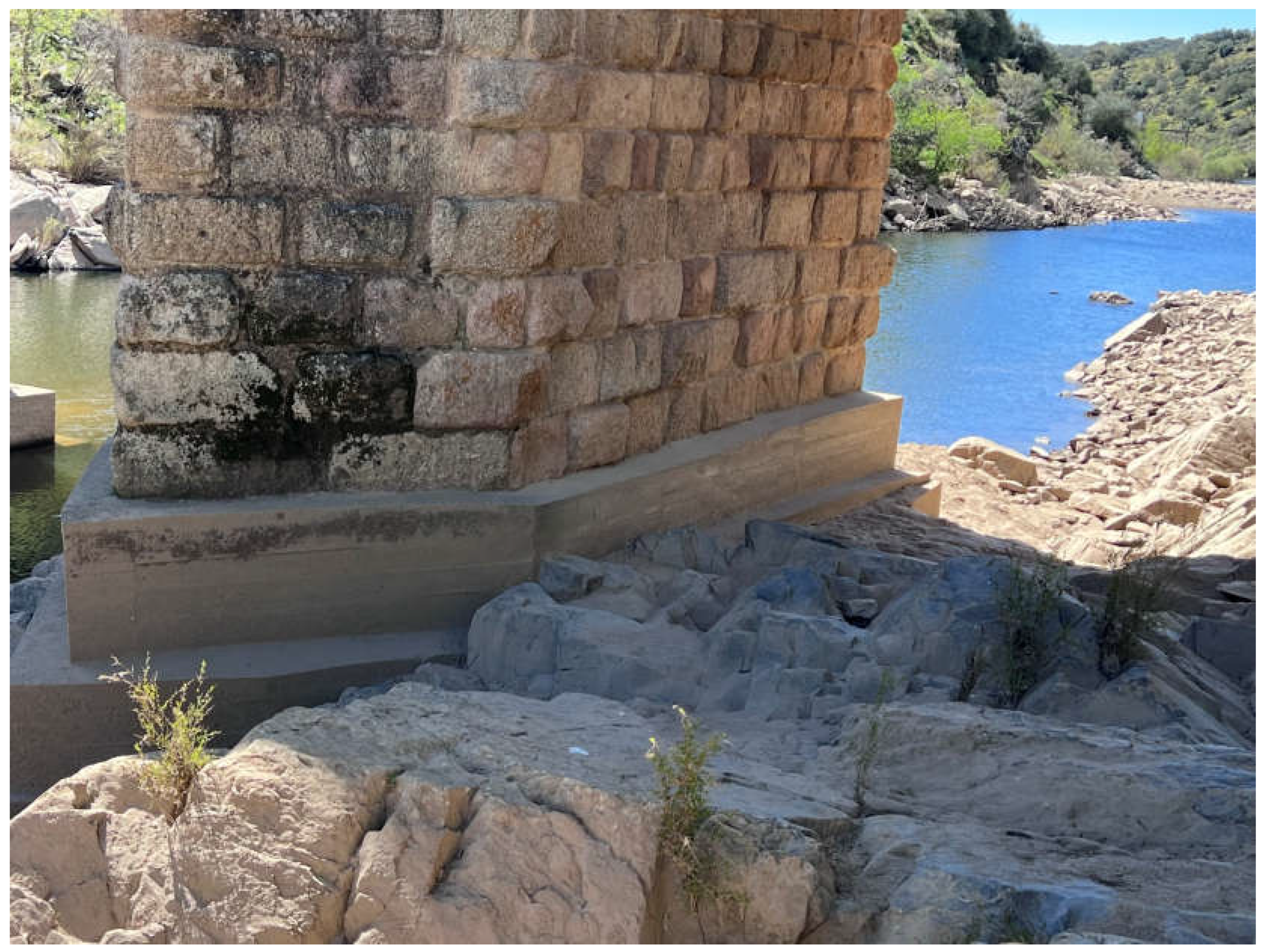
The bridge was built directly on the schistose rock that characterises this section of the Erjas River channel. The first rows of ashlars were placed on it to form the bridge’s piers and abutments (
Figure 3 and
Figure 4).
In 1996, the lower part of the piles was lined at a variable height (
Figure 3 and
Figure 5), an intervention that has been the subject of several less-than-positive evaluations for its aesthetics and effect on the original material [
15]. This will not be discussed in this paper, but cannot be ignored given the research objective.
Based on this premise, the underwater drone used for the inspection was launched from a point with access to the river, downstream of the bridge, and approached the Roman structure against the current to inspect the submerged elements (
Figure 5).
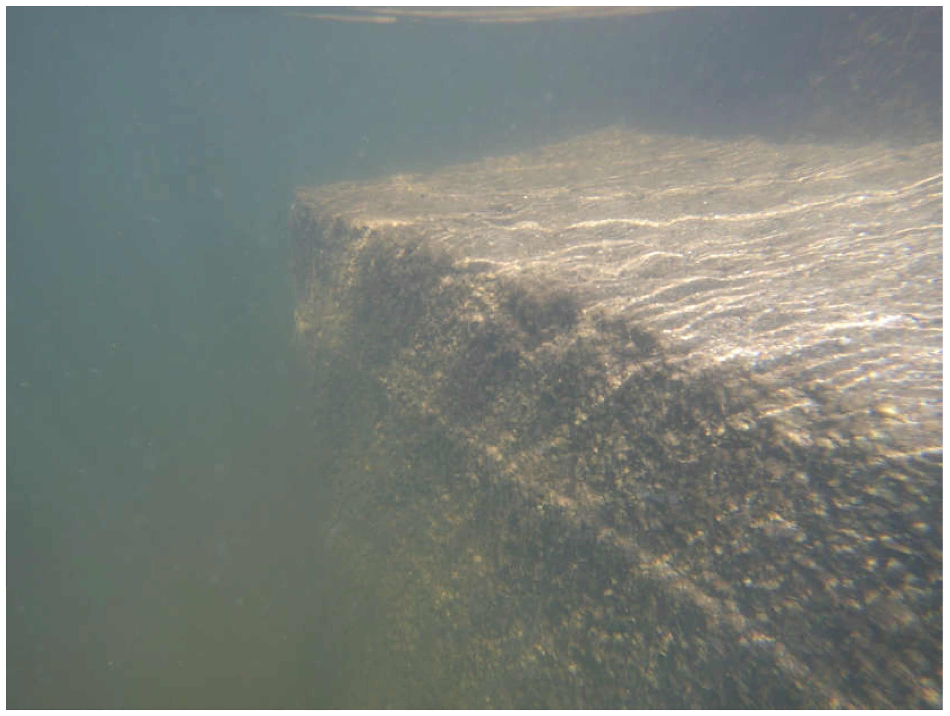
This made it possible to check that there was no deterioration damage to the bridge. The element inspected was the concrete casing mentioned above, which had recently been installed to protect the lower ashlars at the expense of hiding them. The texture of the concrete showed no loss of material due to the direct action of the water (
Figure 6) and was relatively healthy despite being submerged and exposed to flowing water. The drone was able to verify that there were no cracks in the concrete, no exposed steel reinforcement and no disaggregation.
The drone also analysed the soil-foundation complex to check for signs of possible future undermining. The visual inspection of the elevation had indicated that there were no previous settlement or pile rotation problems. However, it is believed that the effect of water flow on the foundation and pile bases is the most common cause of failure in the soil-foundation complex for this type of structure, leading to very serious instability situations as a result of cavity formation and decompression of the soil around the pile bases.
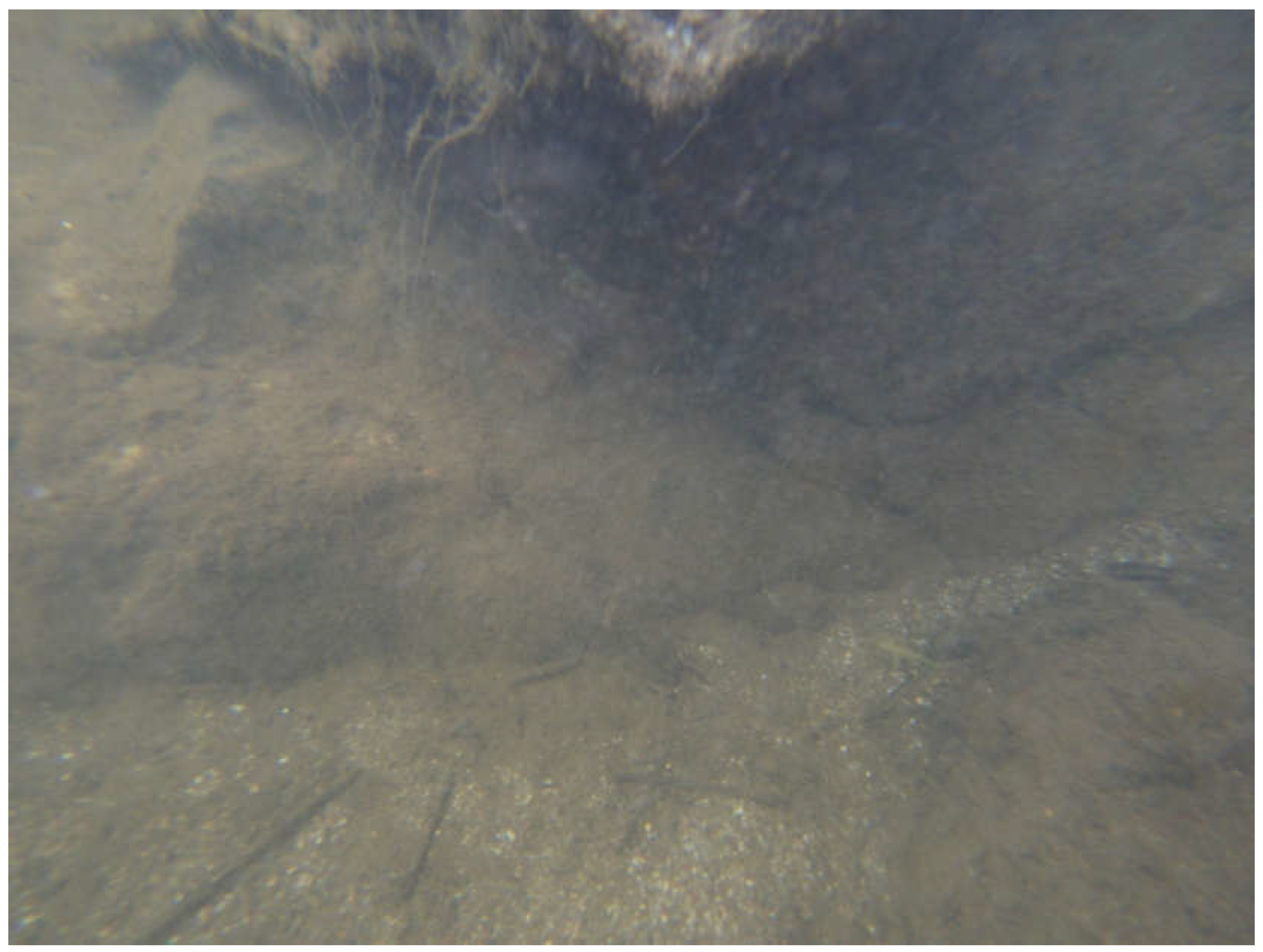
For this reason, in addition to the detailed visual inspection of the submerged support bases, the channel bed in the vicinity of these bases was also analysed with the aid of the drone. This made it possible, firstly, to determine the condition of the bed in the vicinity of the elements and thus to have an idea of the type of material it is made of (sand) and its consistency, and, secondly, to check that there were no significant irregularities in the bed, such as those caused by the formation of horizontal axis eddies in the direction of water flow.
The lack of evidence of destabilisation and mobilisation of significant thicknesses in the riverbed, together with the good condition of the concrete protection, indicates that there has been no increase in the erosive power of the water, at least in recent times. Analysis of the area around the base of the submerged breakwaters showed that no bed material had been torn from the edge by the vertical component of the flow and lifted and carried by the current. When one of the piles was removed (the first, counting from the abutment on the Portuguese side), no evidence of conical depressions in the bed was found. A small depression was found at the edge of the breakwater of this first pile, but its size and depth were minimal and therefore not of concern (
Figure 7).
All this led to the conclusion that the submerged elements of the bridge were in a suitable state of preservation and able to fulfil their function in the short and medium term, thus guaranteeing the absence of undesirable phenomena related to the foundation.
3.2. The San Lorenzo Bridge
The San Lorenzo Bridge (
Figure 8) is a granite ashlar structure that allows road traffic to cross the Tormes River, a tributary of the Duero, on the provincial border between Zamora and Salamanca in Spain [
16,
17], very close to Portugal. Its geometric and structural characteristics make it a Romanesque bridge, although it was built in the 19th century [
18,
19]: its construction was completed in 1871, according to an inscription on its parapet. The bridge is made up of five identical semicircular arches resting on piers topped by rounded breakwaters that make them symmetrical.
The imposing Almendra reservoir, the third largest in Spain, created by the highest dam in the country [
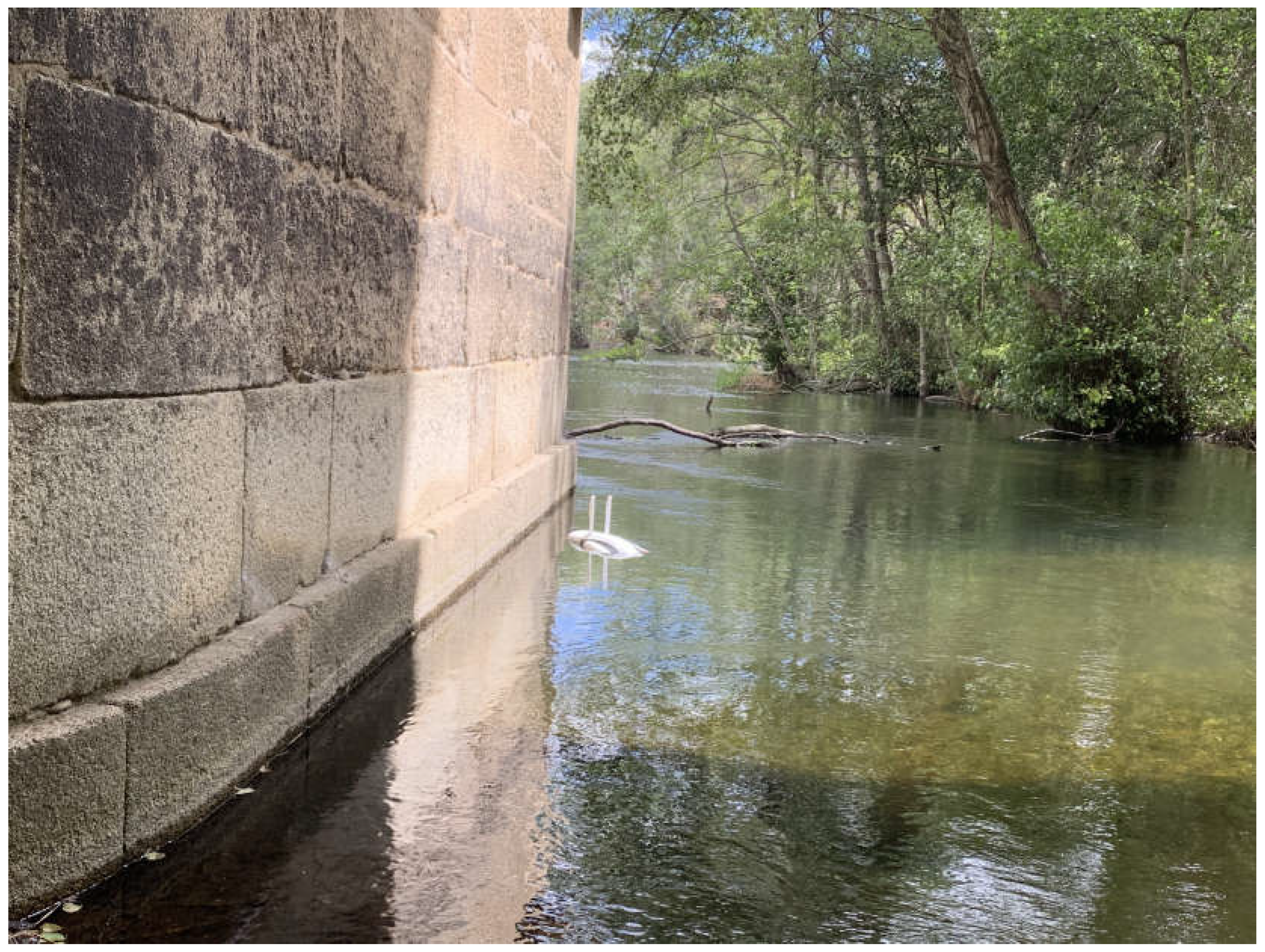
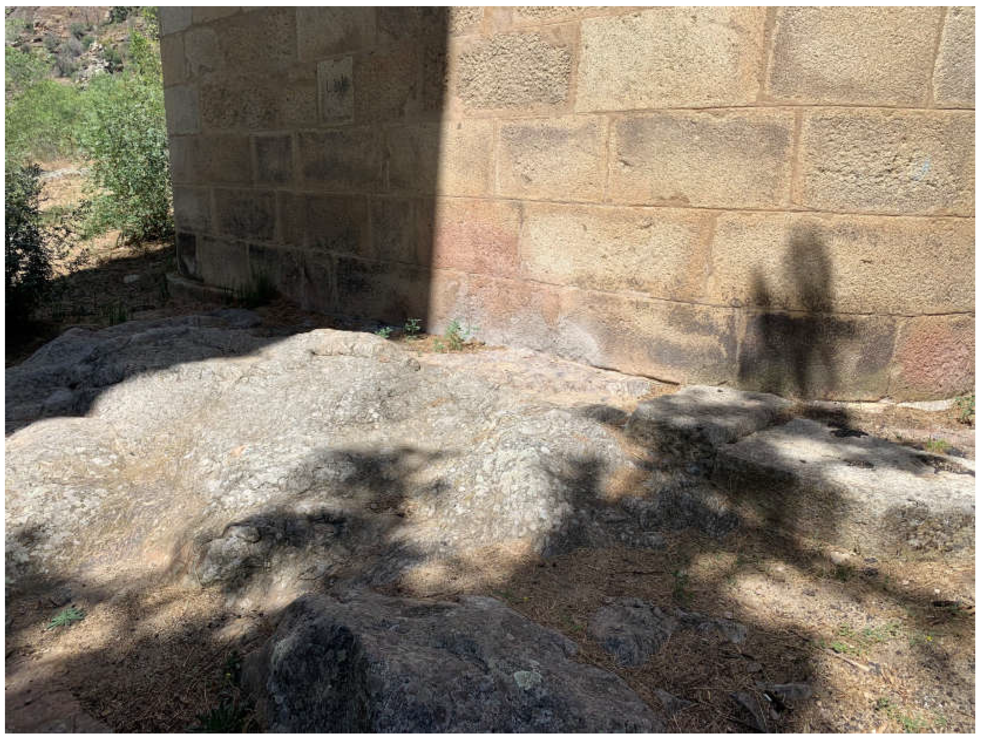
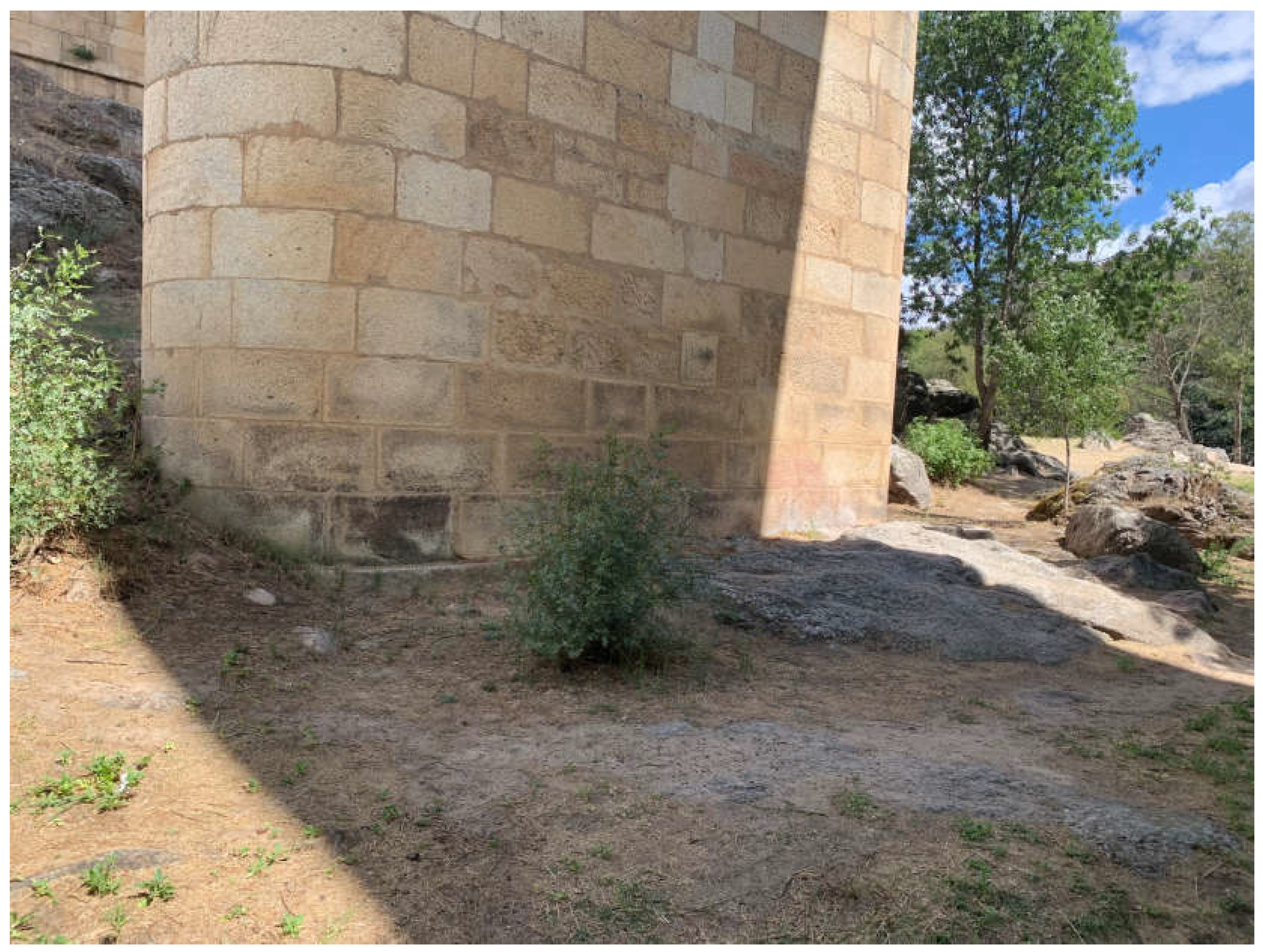
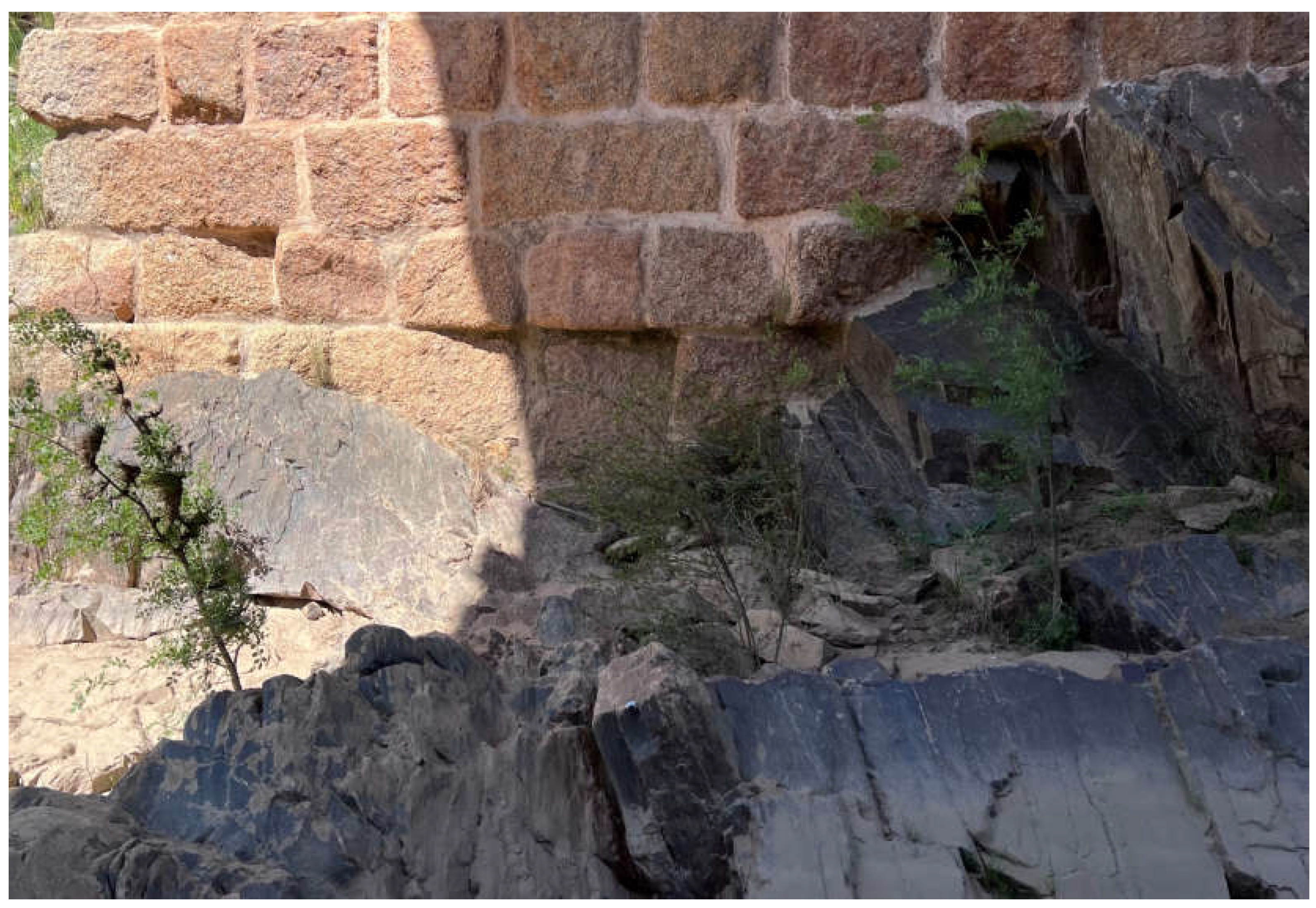
20], was built in 1970 on the Tormes riverbed, just seven kilometres upstream from the bridge. As a result of its construction, the riverbed that the bridge spans and supports is now much smaller than it was during the first hundred years of its life. This made it easier to carry out the experimental inspection and allowed the support of one of the abutments and one of the piers to be seen (
Figure 10 and
Figure 11). These are now outside the riverbed and, given the condition of the first ashlars, must have been submerged before the dam was built. It was also possible to verify that the piers and abutments of the bridge rest directly on outcropping substrates of thick two-mica granite, so characteristic of this area of the Arribes del Duero [
21,
22].
The inspection of this bridge was particularly representative, not only because of the beauty of the structure, but also because of its inherent complexity: the location of the bridge, in the difficult-to-access Puerto de La Cicutina, was compounded by the abundant vegetation in the area, which made it impossible to see the entire structure (
Figure 8).
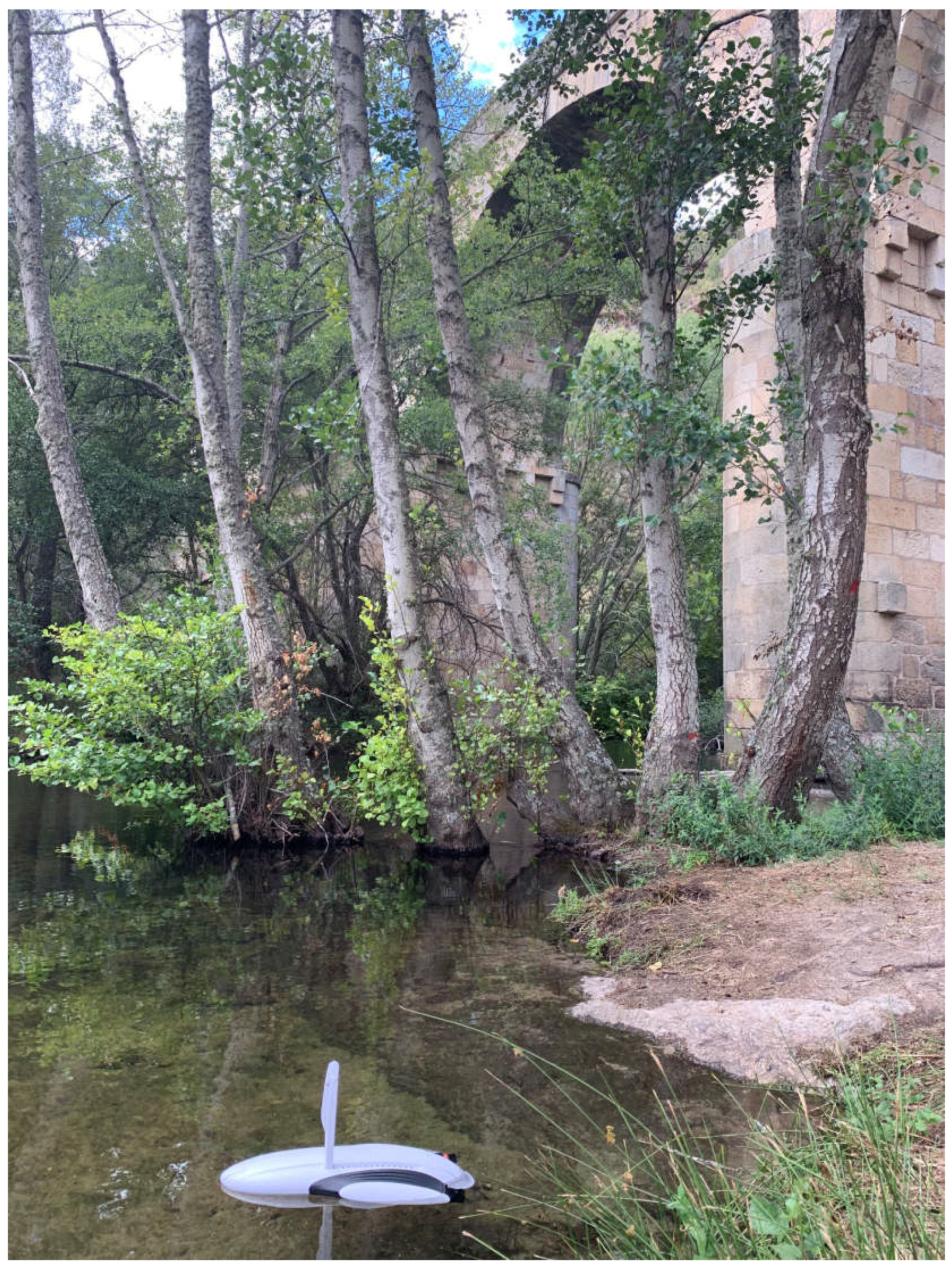
In order to carry out this inspection properly, the pilot had to position himself on a river bank upstream of the bridge, where the riverbed was accessible, and position the drone there (
Figure 1), from where it could follow the course and flow of the Tormes River. In this way, it approached the central piers from upstream of the bridge and was able to carry out the inspection properly (
Figure 9).
Unlike the Segura Bridge, the piers here have no additional concrete elements. The underwater drone confirmed the observation made on the non-submerged elements (
Figure 10 and
Figure 11): the piers rest directly on the ground and the first ashlars rise out of the sand of the riverbed (
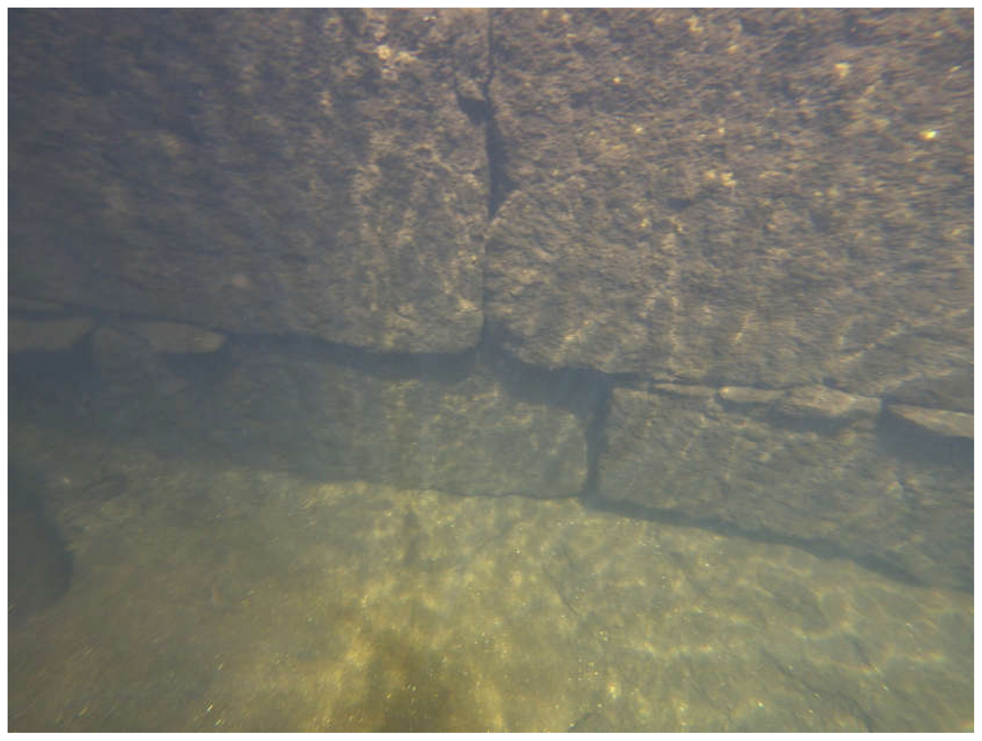
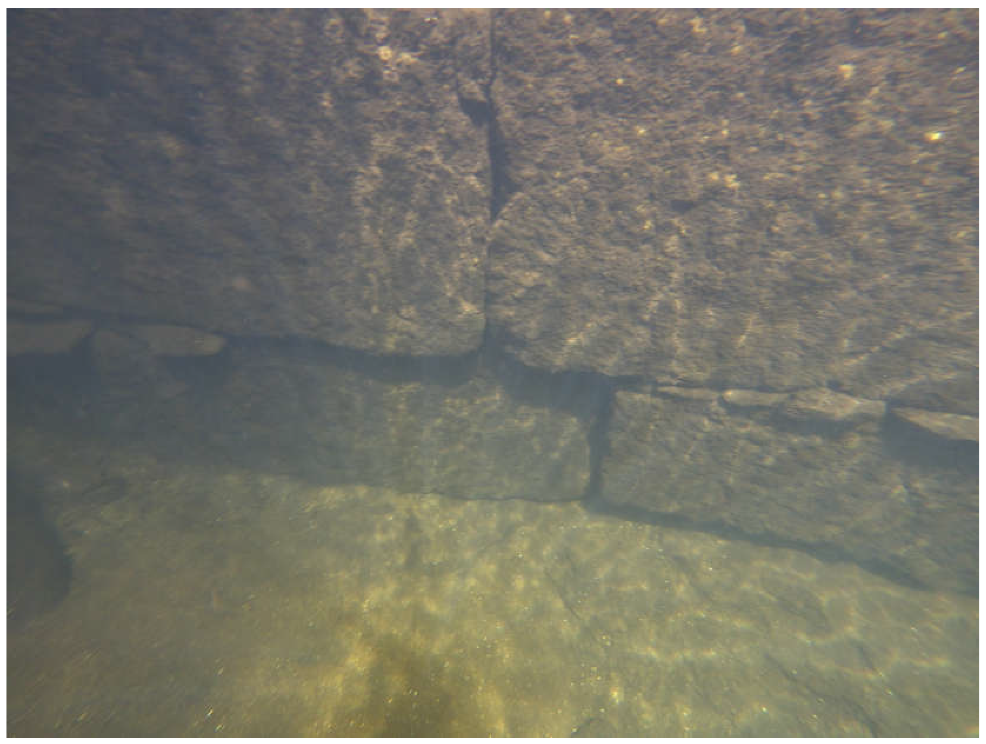
Figure 12 and
Figure 13). As in the previous case, detailed observation allowed us to verify that there were no symptoms of the type that may appear in the superstructure as a result of the main foundation defects: twisting, absolute settlement or differential settlement. A quadcopter drone was used for this purpose.
The underwater drone inspection of the submerged parts confirmed the correct state of the elements underwater: there were no missing granite ashlars and the granite forming the submerged ashlars was in an adequate state of preservation. The presence of stone slabs in various joints between the ashlars and their appropriate location (
Figure 12) appeared to help maintain the position of the ashlars by mutual friction against the erosive action of the river. This would have prevented the need to use grouting mortar, which inevitably tends to dissolve or be lost over time due to the washing action of the flowing water.
It was also possible to verify that the lower part of all the submerged piles was in complete contact with the riverbed. This, together with the absence of deformations in the position of the ashlars, allowed us to confirm the absence of undermining under these piles.
Figure 9.
Underwater drone approaching one of the central piers of the San Lorenzo Bridge from downstream (photo by the author).
Figure 9.
Underwater drone approaching one of the central piers of the San Lorenzo Bridge from downstream (photo by the author).
Figure 10.
View of the first pier of the bridge, counting from the northern abutment (Zamora side), showing its support (photo by the author).
Figure 10.
View of the first pier of the bridge, counting from the northern abutment (Zamora side), showing its support (photo by the author).
Figure 11.
Another view of the pile shown in
Figure 10, with the northern abutment in the background (photo by the author).
Figure 11.
Another view of the pile shown in
Figure 10, with the northern abutment in the background (photo by the author).
Figure 12.
Underwater drone image showing the status of a fragment of the lower part of the pile inspected in the position of
Figure 9 (photo by the author).
Figure 12.
Underwater drone image showing the status of a fragment of the lower part of the pile inspected in the position of
Figure 9 (photo by the author).
Figure 13.
Condition of another fragment of the lower part of one of the inspected piles, in an image captured by the underwater drone (photo by the author).
Figure 13.
Condition of another fragment of the lower part of one of the inspected piles, in an image captured by the underwater drone (photo by the author).
In order to obtain a complete final assessment of the soil-pile interaction under the Tormes riverbed, a visual survey of the material making up the bed adjacent to the submerged elements was carried out using the underwater drone, bearing in mind that this material may undergo some displacement due to the erosive action of the water and, as a consequence, some of these partially submerged piles may be undermined. The analysis showed that there were few irregularities in the bed and that its depth around all the partially submerged elements was virtually identical. The river sand was interspersed with granite elements and the bed remained at a virtually constant level across the section.
All this led to the conclusion that the submerged elements of the bridge were in a good state of preservation and able to fulfil their function in the short and medium term, thus guaranteeing the absence of undesirable phenomena related to the foundation.
3.3. The Brandomil Bridge
The Brandomil Bridge is located in the municipality of Zas, in the province of A Coruña, and spans the Xallas River. Although it does not currently carry traffic, this bridge is particularly representative because it was part of the last stretch of the old Pilgrim’s Way to Santiago de Compostela, linking Santiago and Fisterra [
23]. Until about eighty years ago, it fully supported the passage of carriages on the overlying road. In the 1940s, a new concrete bridge was built a few metres upstream to replace it [
24]. The pilgrims who disembarked at the ports of Muxía and Fisterra on their way to Santiago de Compostela passed through Brandomil and, more specifically, over this bridge [
25]. The width of the road over the bridge is 2.75 m.
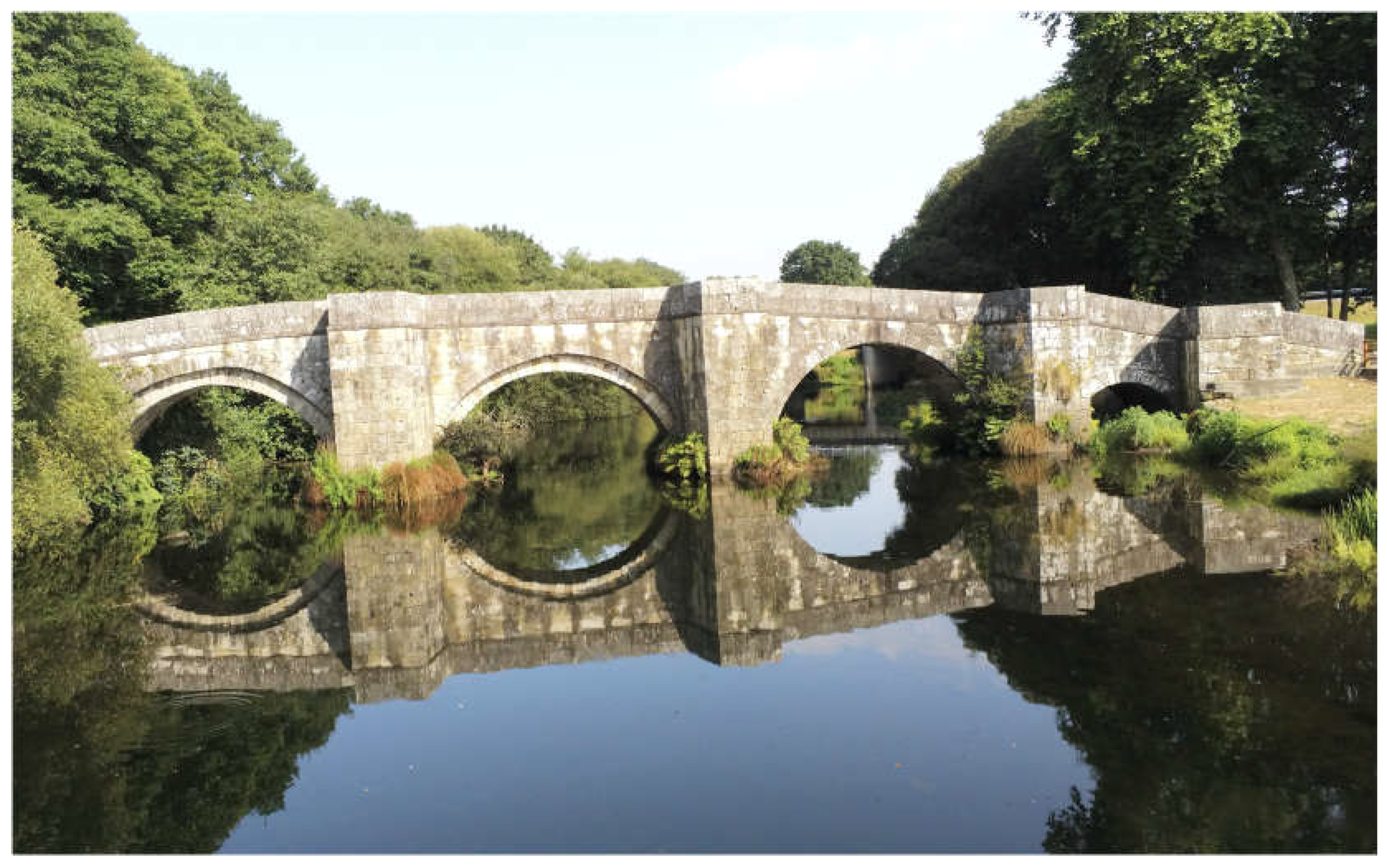
The bridge has four ashlar arches (
Figure 14): three of them with the same span (8.20 m) and the last, at the southern end of the bridge, with a considerably smaller span (4.30 m). The piers, with breakwaters that rise to the top, are very thick, around 3.00 m. The two vaults on the right bank are double threaded. The vaults, tympanums and parapets are made of granite ashlar [
26]. Its constructive and aesthetic characteristics date it to the 17th century, although there is evidence of the existence of an earlier bridge in the same place [
23], even from Roman times [
12].
The piers and abutments of this bridge are built directly on schist and paranisse substrates, with some intercalations of paranphibolites [
22], which are characteristic of this area of the Xallas course, only hidden in some areas of the riverbank by the alluvial plains and the bottoms of the valleys.
Prior to the underwater drone inspection, the bridge underwent a complete and meticulous inspection of its visible parts using a quadcopter drone [
27]. This inspection made it possible to check that there were no defects in the various visible elements that would indicate that the foundation was not functioning properly.
Once again, the underwater drone was launched from a point downstream of the bridge, where the riverbed was accessible (
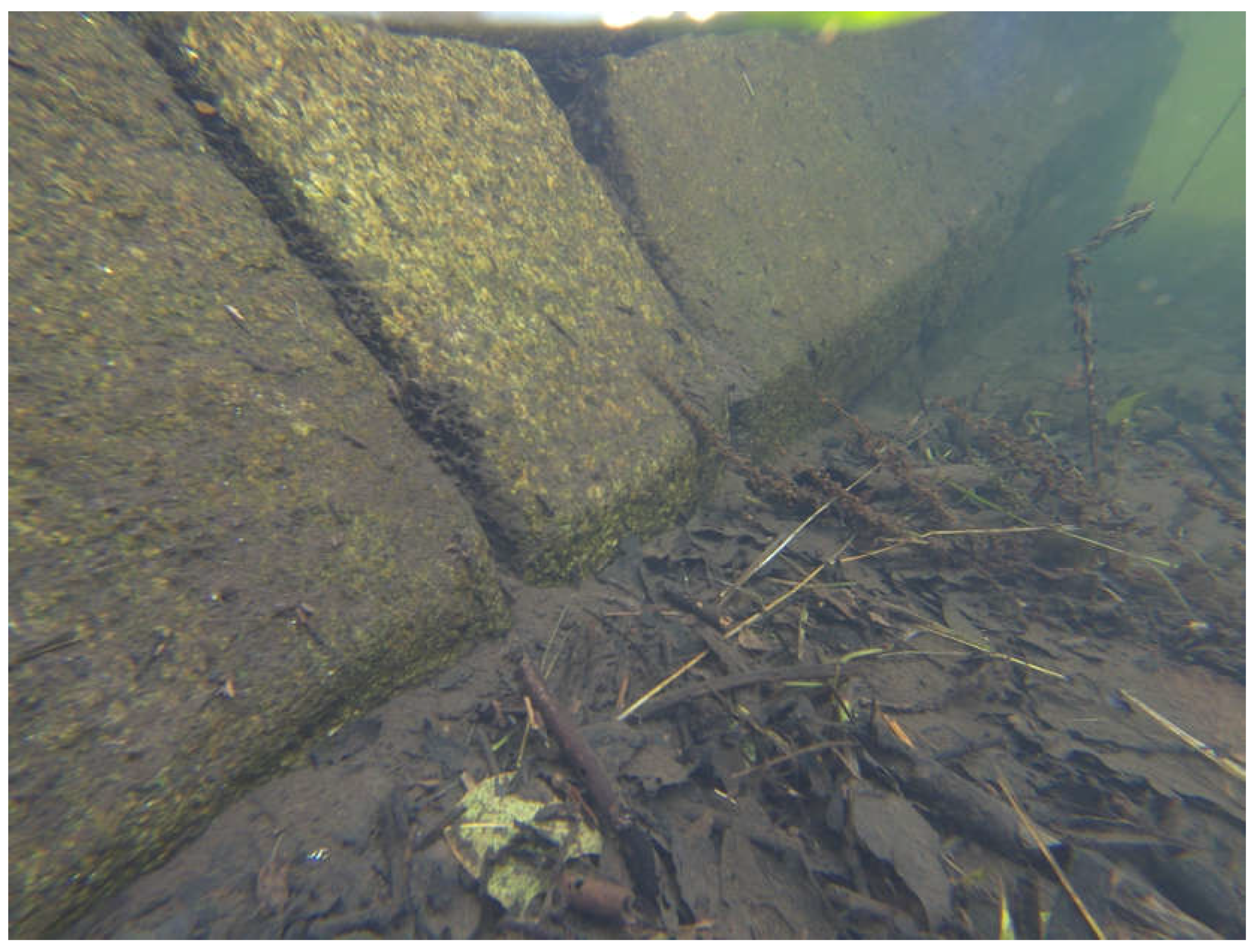
Figure 15), to navigate against the current through the Xallas River towards the stone structure, reaching the bridge to analyse the foundations of the piers built on the riverbed. The drone inspection showed that the submerged part of the elements was in perfect state of preservation (
Figure 16) and that there was a slight settlement in one of the bases, which appeared as a lack of linearity of one of the courses of the ashlars. This slight movement must have taken place some years ago, as there was no evidence of any depressions in the vicinity of the foundations, particularly in the area upstream of the element in question.
The drone inspection showed that the materials forming the base of the submerged piles were in adequate condition: the granite showed no signs of deterioration or erosion from the action of the water, nor were there any missing elements, particularly ashlars.
The analysis of the riverbed in the vicinity of the elements was somewhat more complicated in this case than in the previous ones, due to the presence of thick vegetation remains deposited on a large part of the riverbed surface (
Figure 16). Despite this, it was possible to verify that the level of the riverbed was virtually uniform, with no trenches, deposits or other irregularities that could be caused by the action of water currents on the piles.
Thanks to the drone, it was possible to rule out the existence of any degradation phenomena in the material making up the submerged elements, as well as the presence of any signs of poor performance of the soil-pile assembly due to the actions to which this assembly is exposed. It was therefore concluded that the foundation was in good working order.
4. Conclusions
This research was based on the premise that it is not possible to carry out a complete inspection of an ancient structure to ensure absolute certainty of its true state and stability when part of it is underwater. Therefore, in order to carry out a full assessment, an underwater drone was used to complement the aerial drone. This underwater drone is able to visually inspect the submerged parts of bridge substructures. In this study, this was done on three bridges, as well as the riverbed around each structure, to determine its condition and thus verify the soil-foundation complex.
The inspections confirmed that the submerged elements were in a remarkable state of preservation, with no significant defects or damage associated with deterioration in virtually any of them. Indeed, all of the submerged elements were in good condition.
For the three bridges analysed, the underwater drone inspection confirmed that it is not easy to distinguish between the structural element of the foundation and the bridge pier, which is very common in old masonry bridges. However, the drone was able to rule out any defects in the soil-foundation complex and therefore any signs of settlement in its elements. Only one slight settlement of two ashlars was observed in one of the piers of the Brandomil Bridge, in the area of the joint between the two. After analysing the riverbed in the vicinity, it was possible to confirm that this settlement had occurred some time ago, without having the slightest effect on the pier it supports, and therefore on the rest of the bridge.
The results of the inspections show that a suitable drone can be used to make a detailed and complete visual observation of the submerged elements that make up an important monument. This tool prevented the need for underwater inspections by divers, which would have been necessary if this tool had not been available. The following conclusions can be drawn from this experience:
Underwater drones can be used to visually inspect the condition of the materials that make up submerged bridge elements.
Underwater drones can be used to inspect the material forming the bed adjacent to the substructure, which can be displaced or altered by the erosive action of the water, causing undermining of piles or abutments.
Underwater drones can be used to check the scour conditions in each pile and abutment and to estimate the maximum scour depth.
Underwater drones simplify the planning of traditional underwater inspections.
Underwater drones simplify the field work required to identify and assess the deterioration of each element of a bridge.
Underwater drones reduce all kinds of safety risks for workers involved in underwater inspections, given the inherent dangers: with a drone, for example, no worker needs to expose themselves to the risk of drowning associated with underwater diving.
The six points above represent a significant financial saving that does not in any way imply a reduction in the quality of the work.
Underwater inspection is a very labour-intensive and costly task in terms of human, logistical and financial resources, which is why it is often only used when there is no other option. The main inspection guide [
28] recommends that underwater inspections should be carried out every five years, or more frequently if a structure requires special monitoring, e.g., where the foundations are particularly exposed to the action of water, where a rapid evolution of the hydraulic conditions of the river has been observed, or where some anthropic intervention has occurred that may have harmful effects in the area of influence. The advent of this new type of device, which makes underwater inspections much safer and more accessible, can be an incentive to carry out these inspections more frequently, resulting in greater durability and better conservation of structures with submerged elements. The experience gained from the experimental inspections carried out for this study can be extrapolated to many other works of the same nature, opening up an infinite range of possibilities for these small devices, which are undoubtedly here to stay and are sure to change the way certain elements are inspected.
This paper has focused exclusively on the use of underwater drones to inspect heritage structures with partially submerged elements. Although it was not used here, the underwater drone involved in this research has a built-in probe that would make it possible to carry out perimeter bathymetry around the element to be inspected. In other words, this tool could be used to measure the depth of the bed around the element, with periodic inspections providing an idea of how the bed is changing over time. Furthermore, when diagnosing the first signs of undermining of an element, this built-in probe would make it possible to measure the length of the bed on which the element is not in contact and to quantify the depth of the diagnosed undermining.
This option opens up a wide range of basic operations for proper and rapid assessment of foundation defects, as a bathymetric survey of the channel would make it possible to define the longitudinal profile of the riverbed, as well as its cross-sections upstream and downstream of the bridge. Hydraulic calculations can then be carried out to determine the basic parameters of the object under study, such as river velocity or water depths at particularly sensitive points, such as around the piers or abutments.
Similarly, the drone model used can be equipped with small accessories. This possibility should be explored, for example to allow a small sample to be taken during a campaign.
Finally, this research focused on the submerged elements of three bridges built to cross low-flow and low-depth rivers. This was done using an underwater vision drone that navigated on the surface at all times. In practice, and in a more powerful river, the drone’s range could be limited and it could provide partial and biased information. However, there are indications of other devices on the market that have the ability to dive underwater and not just stay on the surface, making it possible to reach and inspect deeper and inaccessible elements.
References
- Rodríguez Elizalde, R. Use of Remotely Piloted Aircraft (Drones) for The Inspection of Architectural Heritage and Ancient Structures. In Proceedings of the 9th REHABEND Congress, Construction Pathology, Rehabilitation Technology and Heritage Management, Granada, Spain, 13–16 September 2022. [Google Scholar]
- Reza Choudhury J, Hasnat, A. Bridge collapses around the world: Causes and mechanisms. Proceeding of IABSE-JSCE Joint Conference on Advances in Bridge Engineering-III, Dhaka, Bangladesh. 2015. p. 26-34.
- Zampieri P, et al. Failure analysis of masonry arch bridges subject to local pier scour. Engineering Failure Analysis, 2017, vol. 79, p. 371-384. [CrossRef]
- Rodríguez Elizalde, R. Use of RPAS (drones) for masonry arch bridges inspection: application on Grajal Bridge. International Journal of Current Research 2022, 14, 21954–21960. Available online: http://journalcra.com/sites/default/files/issue-pdf/43791.pdf (accessed on 7 July 2024).
- Rodríguez Elizalde, R. Utilisation de Systèmes d’Aéronefs Télépilotés pour l’Inspection d’Anciennes Constructions (in French). Current Opinion 2022, 2. Available online: https://www.currentopinion.be/index.php/co/article/download/121/52 (accessed on 7 July 2024).
- Rodríguez Elizalde, R. Use of RPAS (Drones) for Old Bridges Inspection: Application on Ponte Olveira Bridge. International Journal of Innovation Scientific Research and Review 2022, 4, 3487–3493. Available online: http://journalijisr.com/sites/default/files/issues-pdf/IJISRR-1035.pdf (accessed on 7 July 2024).
- Navareño Rojo, Á. Reconocimientos especiales del estado de cimentaciones en puentes (in Spanish). RUTAS Revista de la Asociación Técnica de Carreteras. 2010; 139. Available online: http://www.atc-piarc.com/rutas_descargar.php?numID=139 (accessed on 7 July 2024).
- ATC-PIARC. Cimentaciones de fábrica en puentes (in Spanish). Grupo de trabajo de Puentes de Fábrica del Comité de Puentes de la Asociación Técnica de Carreteras (PIARC). 2008; 149 p.
- Durán Fuentes, M. La Construcción de Puentes Romanos en Hispania (in Spanish). Santiago de Compostela, Spain: Dirección Xeral de Patrimonio Cultural, Consellería de Cultura e Deporte (Xunta de Galicia); 2005: 366 p. Available online: https://www.traianvs.net/pdfs/2005_duran.pdf (accessed on 7 July 2024).
- Viollet-le-Duc E. La Construcción Medieval (in Spanish). Madrid, Spain: Instituto Juan de Herrera, Centro de Estudios Históricos de Obras Públicas y Urbanismo (Ministerio de Fomento); 1996: 313 p.
- González Parejo, J.M. Puentes de Fábrica Romanos y Medievales en la Provincia de Cáceres (in Spanish). Ph.D. Thesis, Escuela Técnica Superior de Ingenieros de Caminos Canales y Puertos (UPM), Departamento de Mecánica de los Medios Continuos y Teoría de las Estructuras, Madrid, Spain, 2014; 672p. Available online: https://oa.upm.es/30316/ (accessed on 7 July 2024).
- Fernández Casado C. Historia del Puente en Spain: Puentes Romanos (in Spanish). Madrid, Spain: Colegio de Ingenieros de Caminos, Canales y Puertos, Editorial Doce Calles; 2008: 602 p.
- Durán Fuentes, M. Puentes Romanos Peninsulares: Tipología y Construcción (in Spanish). In Proceedings of the 1st Congreso Nacional de Historia de la Construcción, Madrid, Spain, 19–21 September 1996; Available online: http://www.traianvs.net/textos/puentes03.htm (accessed on 7 July 2024).
- Durán Fuentes, M. Técnica y Construcción de Puentes Romanos (in Spanish). In Proceedings of the Elementos de Ingeniería Romana: Congreso Europeo “Las Obras Públicas Romanas”, Tarragona, Spain, 3–6 November 2004; Available online: http://www.traianvs.net/pdfs/2004_06_duran.pdf (accessed on 7 July 2024).
- Durán Fuentes, M. Algunas Cuestiones Teóricas y Prácticas sobre la Reparación de los Puentes de Fábrica (in Spanish). In Proceedings of the 1st Congreso Internacional de Carreteras, Cultura y Territorio, La Coruña, Spain, 3–5 March 2010; Available online: https://www.traianvs.net/pdfs/2010_duran.pdf (accessed on 7 July 2024).
- Cadiñanos Bardeci, I. Puentes en Zamora (in Spanish). Anuario del Instituto de Estudios Zamoranos Florián de Ocampo, 1997, no 14, p. 597-626. Available online: https://dialnet.unirioja.es/descarga/articulo/6547989.pdf (accessed on 7 July 2024).
- Villary Macías, M. Historia de Salamanca (in Spanish). Salamanca, Spain, 1887. 3 vol. Available online: https://bibliotecadigital.jcyl.es/es/consulta/registro.do?id=5850 (accessed on 7 July 2024).
- González Matellán, J.M. Rastreo por Zamora y búsqueda de puentes a la Antigüedad/Trawling through Zamora and Searching for Bridges to the Antiquity. Boletín de Literatura Oral 2017, 415–437. [Google Scholar] [CrossRef]
- Hidalgo Rodríguez, D. Prehistoria e Historia Antigua de Arribes del Duero a propósito de Trabanca (in Spanish). Perspectivas y problemas de la Arqueología en el entorno rural. El Futuro del Pasado, 2010, vol. 1, p. 395-410. Available online: https://revistas.usal.es/uno/index.php/1989-9289/article/view/24517/23224 (accessed on 7 July 2024).
- Berga Casafont, L. Forma y función en presas y embalses (in Spanish). Ingeniería y Territorio, 2008, 81, p. 80-85. Available online: http://www.ciccp.es/revistait/textos/pdf/09-Luis%20Berga%20Casafont.pdf (accessed on 7 July 2024).
- Prada Llorente, E.I. Paisaje agrario: antropología de un territorio. Ciudad y Territorio Estudios Territoriales (in Spanish), 2005, p. 343-372. Available online: https://recyt.fecyt.es/index.php/CyTET/article/view/75551 (accessed on 7 July 2024).
- García de Miguel, J.M. Tratamiento y conservación de la piedra, el ladrillo y los morteros en monumentos y construcciones (in Spanish). Madrid, Spain: Consejo General de la Arquitectura Técnica de Spain; 2009: 684 p.
- Urgorri Casado, F. Puentes y caminos en la Provincia de La Coruña (in Spanish). Revista Instituto José Cornide de Estudios Coruñeses, 1969, no 5, p. 199-246.
- Roseman, S. “How we built the road”: the politics of memory in rural Galicia. American Ethnologist, 1996, vol. 23, no 4, p. 836-860. Available online: https://www.jstor.org/stable/646186 (accessed on 7 July 2024).
- Lema Suárez, X.M. Topónimos con historia do camiño de Santiago a Muxía. Os camiños de Santiago de Europa a Galicia: lugares, nomes e patrimonio, 2022. p. 175-212. [CrossRef]
- Carvajal Alcaide, R.; Cortés López, M.E. Aportaciones gallegas para la historia del corte de la piedra en Spain: Los cuadernos de Juan de Portor y Francisco Sarela. Proceeding of 8th Congreso Nacional de Historia de la Construcción Madrid, Spain; Octobre 9 – 1221, 2013. Available online: http://www.sedhc.es/biblioteca/actas/Aju%20017%20Carvajal.pdf (accessed on 7 July 2024).
- Rodríguez Elizalde, R. (2023). Use of Unmanned Aircraft (Drones) for the Inspection of Architectural Monuments and Ancient Constructions. Journal of Engineering Research 3 (18), 2023. [CrossRef]
- VVAA. Guía para la realización de inspecciones principales de obras de paso en la Red de Carreteras del Estado (in Spanish). Madrid, Spain: Secretaría General Técnica, Ministerio de Fomento; 2012: 355 p. Available online: https://www.mitma.gob.es/recursos_mfom/0870250.pdf (accessed on 7 July 2024).
|
Disclaimer/Publisher’s Note: The statements, opinions and data contained in all publications are solely those of the individual author(s) and contributor(s) and not of MDPI and/or the editor(s). MDPI and/or the editor(s) disclaim responsibility for any injury to people or property resulting from any ideas, methods, instructions or products referred to in the content. |
© 2024 by the authors. Licensee MDPI, Basel, Switzerland. This article is an open access article distributed under the terms and conditions of the Creative Commons Attribution (CC BY) license (http://creativecommons.org/licenses/by/4.0/).
